Abstract
In this paper, we investigated the cascade controller of a motor-driven deep-sea robot cable system (MDRCS), which consists of the outer loop system and the inner loop system connected by a motor thrust with unknown factors, typically forming a crucial problem along with actuator failures, and is accommodated by a fault control created for the deep-sea model. Furthermore, the non-linear disturbance observer compensates for the external disturbance by using the high-gain state observer to estimate parameters and reduce the effects of measurement inaccuracy from the sensors. We suggested an output feedback boundary controller for the outer loop system to get the thrust and eliminate the transverse cable vibration as well as a multiplicative inverse controller for the motor system to form a cascade controller. The Lyapunov approach is then used to demonstrate the stability of the deep-sea robot cable system and motor system. The results demonstrated the effectiveness of the suggested controller and fault control in the presence of the actuator fault, presented with the appropriate parameters on MDRCS.
1. Introduction
Underwater robots are now most frequently used in the exploration and exploitation of marine resources, widening their use in engineering fields [1,2,3,4,5] due to the rapid growth of remote operated vehicle (ROV) in information interaction, depth in working, and recycling, etc. The motor-driven deep-sea robot cable system (MDRCS) is a cascade system made up of an offshore vessel, a flexible cable, a ROV, and motors in Figure 1. Numerous studies on the suppression of vibrations in flexible deep-sea bodies have been started by scientists because flexible umbilical cable is prone to vibration, which affects the operating environment of the ROV [6,7,8].
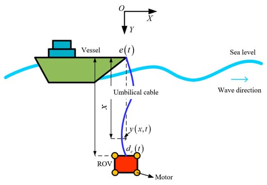
Figure 1.
Motor-driven deep-sea robot cable system (MDRCS).
Systematic vibration control research is important for real-world engineering applications. The first inverse adaptive controller was proposed to enable global state regulation and track for non-linear systems with unknown parameters in [9] and a smooth projection algorithm [10] was then proposed to design robust adaptive controllers for non-linear systems with modelled dynamics, addressing the parameter drift in the adaptive control system. Boundary control is widely used because it can reach a stable state simply by applying force at the boundary to dissipate system energy.
A controller that combines adaptive inversion and sliding model techniques is developed for effective target tracking and robustness while taking into account external disturbances [11]. A new parameter adaptive approach is put out in the literature [12] to deal with the problem brought on by the increased number of siding models and maintain the stability of the system. For the non-linear systems, fuzzy control [13] is widely used in the vibration control due to the benefits of not requiring an accurate mathematical model, being more robust and tolerant. The author proposed a fuzzy control rule in [14] and created a direct adaptive fuzzy controller that adapts much more quickly than traditional controllers. For the hand rehabilitation training robot with two actuators, adaptive fuzzy control is used to compensate for the patient variable forces and chattering effects in [15]. Additionally, neural networks have been extensively employed in system control because of its great approximation impact without prior knowledge. Regression wavelet neural networks are demonstrated to be applied to the control design of uncertain flexible jointed robots in the literature [16], where weights are trained online to approximate the model’s uncertainty and numerical analysis demonstrates good control performances.
It is important to consider how the nonlinearity of the control input limits the control impact in order to increase the controller’s applicability. An inverse controller is proposed to reduce the vibration of a flexible string to solve the input dead zone problem [17]. It compensates for the flexible string’s input dead zone effect using a radial basis function neural network, and it employs a disturbance observer to monitor and estimate the external disturbance. In [18], the researcher used a high-gain state observer to predict the system’s unknown boundary states and an adaptive output feedback boundary controller to stabilize the flexible robotic arm system. An input saturation model is introduced, and the inverse approach is used to construct a hovering saturation controller [19] for UAVs hovering in quasi-static situations. This compensates for the actuation limits and shows the system’s overall stability. Both construct the controller to accomplish the desired trajectory and handle the control output limitations using asymmetric time-varying potential barrier functions. By developing a differential equation and monitoring mistakes, [20] created a state-feedback robust adaptive controller that can be used for hysteretic control-constrained systems with similar backlash without the need for an upper bound on the unknown term. Additionally, in [21], a smooth adaptive control scheme is put forth as a solution to the hysteresis controller fault problem. The findings demonstrate that under this control, the controller has good control in both normal and fault conditions. Both construct the controller to accomplish the desired trajectory and handle the control output limitations using asymmetric time-varying potential barrier functions by developing a differential equation and tracking errors.
The inner loop control and the outer loop control make up the cascade control. The inner loop control, which regulates the primary variables of the outer loop, such as flow stabilization control, uses the output of the outer loop control as its control target. In [22], the inner and outer-loop sliding-mode controllers are constructed for the mechanical and hydraulic subsystems, respectively, to serve the purpose of robot trajectory tracking for a six-degree-of-freedom parallel hydraulic robot system. In [23], a cascade controller is proposed, where the inner loop controls the cable’s driving force and the outer loop controls the robot’s end position. The uncertainty of the structure is considered to ultimately accomplish the stability of the cable-driven robot system. The cascade PID control for maglev actuators is designed in [24], the control effect can be improved by reducing the phase hysteresis of the system and increasing the control gain. Finally, the results of the experimental and numerical simulation show that the regulator functions well in the range of 1~25 Hz. The design of the flexible system controller is discussed in the paper, but further research on the control force applied by the motor system is not included. The link between motor rotation speed and motor thrust is developed in this work with reference to the literature [25]. To obtain a motor control voltage that effectively suppresses the boundary vibration of the umbilical cable, a cascade controller is created for MDRCS. The main task of this paper is:
1. For outer loop control of the deep-sea robot cable system, a boundary output feedback controller with disturbance observer, state observers and actuator fault are designed. A fault control makes it possible to connect the inner and outer loop systems specifically under the unknown thrust factor situation. Finally, the stability of the system is demonstrated by the Lyapunov method.
2. A multiple inverse controller is purposed for the inner-loop motor system with a non-matching uncertain non-linear system. The disturbance observer and a smooth, robust term are designed for the external disturbances of two subsystems, respectively, proving their stability by the Lyapunov method.
3. The validity of the proposed controller and the fault control are respectively verified by comparing the results of the different controllers and actuator fault, with the numerical analysis.
2. System Model and Problem Statement
2.1. Preliminaries
To facilitate subsequent controller design and stability proofs, the system equations for the deep-sea robot cable system and the motor system are given separately in this section. The following assumptions and lemmas are given. The notation in the following of the paper is shown in Table 1.

Table 1.
The notations in the paper.
Assumption 1.
Deep-sea robot cable system and motor system also suffer from external disturbances. If external disturbances have upper boundary, that there exists constant, such that , , and. It is reasonable because the energy of the systems is finite.
Assumption 2.
It assumes that the time differential of the external disturbances is also bounded.
Lemma 1
[26]. If is a positive-function defined on , and satisfies the inequality:
where integrate both sides of the inequality and substitute the initial value, we can obtain the inequality as
Lemma 2
[27]. If the functions are defined on , we have
Lemma 3
[28]. If the differentiable function defined on satisfies , the following inequality can be obtained
2.2. Deep-Sea Robot Cable System Model
For the outer-loop deep-sea robot cable system with seawater disturbances, the transverse vibration model of the variable-length umbilical cable with infinite degrees of freedoms is established by Hamilton’s principle. Then, we obtained the governing equations as
where, is purpose control force.
is the tension of the umbilical cable; and are the thrust factor and the angular speed of the i-th motor, respectively; is the number of motors; is the upper boundary disturbance; ; .
The meanings of other system parameters are listed in Table 1.
Remark 1.
For convenience and clarity, the symbols of derivative are introduced as:, , and.
To facilitate the subsequent controller design, the effect of the disturbance at the first end of the system is considered as an unknown term and the above equation is further organized as:
where ; ; , are lateral force due to the upper boundary disturbances.
2.3. Motor Model
For the inner-loop motor system, we use a two-state model [25] consisting of motor torque control and motor voltage control equations. Furthermore, considering the motor system uncertainties and effects of unknown external disturbances, the motor equations can be written in matrix form as
where is the angular speed vector of the motors, current vector of the motors.
Remark 2.
The parameter matrix and state vectors in the motor equations are defined as ; are diagonal matrix of motors parameters; , are the same definitions; indicates uncertain item of the system.
Definitions for design convenience are shown in the following equation
Subsequently, the motor equation can be simplified and written as
The motor system aims to obtain the control force through combining the thrust generated by the motors rotational speed, and the purpose rotational speed of each motor is obtained by the fault control. Subsequently, the final motor control voltage can be obtained by applying it to the equation of the motor system.
3. Control Design
MDRCS is a cascade system composed of the deep-sea robot cable system and the motor system. For this cascade system, output feedback boundary control under actuator failure is designed and the control strategy is shown in Figure 2. For MDRCS, the working principle is that the motors provide boundary thrust for the umbilical cable to suppress the transversal vibration and provide a stable working environment for the ROV. The transverse vibration and boundary inclination of the umbilical cable is measured by sensors at the boundary. However, measurement errors are unavoidable, and the influence is further increased when we obtain an unknown second-order value by direct time differentiation. This in turn leads to result in a poor control effect, which may be manifested by slow convergence and large fluctuations. Therefore, a high gain observer is used to estimate the unknown state quantities and design an output feedback boundary controller to suppress the umbilical cable transverse vibration. For motor control systems that may fail when operating under the sea, fault control is introduced to compensate for thrust when the motors have faults. It can also solve the problem of unknown thrust factors. The motor system, inner-loop, is a non-matching uncertain non-linear system, so the controller is designed by using multiple inverse methods. For unknown terms such as external disturbances and system uncertainty terms, a non-linear disturbance observer is designed to observe the disturbances.
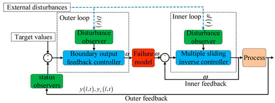
Figure 2.
Cascade control of MDRCS.
3.1. Output Feedback Boundary Controller for Deep-Sea Robot Cable System
For the problem of actuator fault in the deep-sea robot cable system, the fault control input can be expressed as
where , , and represent actual output, design output, and jammed value of the controller, respectively. represent the time of failure of the controller.
The is a fault control design parameter, the specific values are taken as follows:
At this point, the controller is partially disabled, with ;
This means that controller is completely disabled with ;
The controller is no fault.
According to Lemmas from [29], the system state quantities and measured by the boundary sensors can be used as inputs to the high gain state observer respectively. As for the deep-sea robot cable system, the observer is designed with n = 2. Define , , and design of a high gain state observer as
The observed value of the unmeasurable state is . Then the observation error is defined as:
Similarly, we can define , , so the other high gain state observer is designed as
and the observation error as
In addition, for the external disturbance of the deep-sea robot cable system, the non-linear disturbance observer is designed as
For the deep-sea robot cable system, combined with the system states estimated by the high-gain observers, the output feedback boundary control can be designed as
where is a positive design constant, and , is the estimated value of external disturbances.
If the uncertain value KTi and the types of the motor faults are known. The i-th motor control input can be designed as
and satisfies equation
where is an unknown vector, is a known vector. They are both n + 1-dimensional vectors. can be designed as
and the adaptive law for unknown vectors is
adaptive error is defined as
where is actual vector, is estimated vector.
No-fault case: According the Equation (24), the vectors take the value as
We select the alternative Lyapunov function as
where
Based on the Lemmas 3 and Assumptions 1, the alternative Lyapunov functions satisfies the below inequalities
where are positive constants (proof process is in Appendix A).
where are positive constants (proof process is in Appendix B).
Theorem 1.
For the deep-sea robot cable system, when the Assumptions 1 is satisfied and the reasonable parameters are chosen, boundary state feedback controller (22) designed by disturbance observer (21), high gain state observers (17)–(19), and control failure (16) can keep state variablefor closed-loop deep-sea cable systems bounded.
Proof of Theorem 1.
Multiply both sides by , the Equation (36) can be written as
Then integrate the inequality over , we have
Applying the Lemma 3 for Equations (32) and (35), we can obtain
Combining the two Equations (38) and (39), the following inequality will be obtained
with .
Take the time limit for the Equation (40), we have
Fault case: let , substitute the fault control (16) into (24), we obtained the equation
where is a normal subset of the control motors.
The vectors take the value as
We choose the similar Lyapunov function, the only difference from above is fault adaptive error. Because the adaptive law for unknown vectors approximated well, we have similar conclusions and proof methods with the non-fault case, so the process of the proof is omitted. □
3.2. Multiplicative Inverse Controller for Motor System
The main objective of the motor system is to provide the required speed to suppress the transversal vibration of the umbilical cable. The relationship between the motor speed and motor control voltage is non-linear, a multiple inversion controller is designed for the system. Based on the literature [30], the control motor equation can be written as
Simplified formulation of the motor control equations as a general form of multi-slip inverse control design
where .
are the defined state variables as . Subsequently, define the two sliding surfaces for the system as
where are the desired value of the system states , respectively, and is the desired speed of rotation obtained by the above control.
Step 1: Derivation for the first sliding surface
To ensure that the reaches the sliding surface 1 and moves stably in the neighborhood of the sliding surface 1, design virtual control laws as
where is upper bound of the uncertainty part . As the subsequent design requires derivation of the virtual control law, write the non-differentiable term as
with, . So, the virtual control laws can write as
Define the first alternative Lyapunov function as
Derive for (53) and substitute absolute value inequality, the following inequality can be obtained
If , the above inequality can be written as
Step 2: Derivation for the second sliding surface
where,
To ensure that the reaches the sliding surface and moves stably in the neighborhood of the sliding surface 2, design the equivalent control law as
where is upper bound of the uncertainty part .
Designing non-linear disturbance observer’s observations for unknown disturbances in conjunction with system equations. The observer equation is
where is the estimated value of .
And define disturbance errors as
Design the switching control law as
So, the actual control law is
Theorem 2.
For the motor system, the assumptions 1 is satisfied, use the nonlinear disturbance observer (61) and the control law (64), bounded system state can be guaranteed. The motor system is bounded, stable, and finite time convergence.
Proof of Theorem 2.
Define the Lyapunov function as
Deriving (65) and substituting (56), the following inequality can be obtained
Theorem 3.
For the cascade system MDRCS, when Assumption 1 is satisfied and the reasonable parameters are chosen, Equation (80), the cascade controller composed of the boundary state feedback controller Equation (22) and multiplicative inverse controller (64) can keep the state variablefor closed-loop and bounded, and both inner and outer loop systems are stable.
4. Result Discussion
In this section, the numerical solution obtained by the finite difference method of the system verified the performance of the cascade control design in the presence of actuator fault, external interference, and variable length. First of all, the numerical results of boundary transversal vibration of MDRCS under the following controllers are compared, for the purpose of proving the validity of the proposed control (22).
- Without control.
- PD control.
The PD control is selected as
where , .
The proposed control Equation (22) with the control gains: , . The boundary vibration of MDRCS is displayed in Figure 3, and the parameters of the system are specified in Table 2.
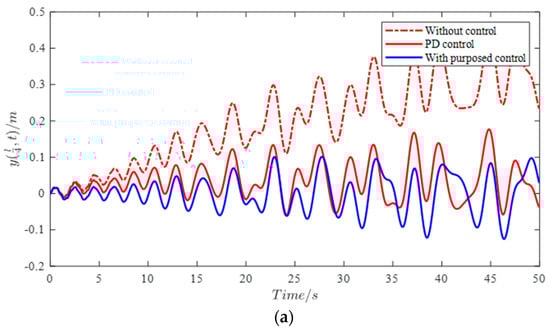
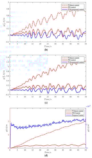
Figure 3.
The vibration at four positions of the umbilical cable with different controllers. (a) . (b) . (c) . (d) .
Table 2.
The parameters of the systems in the numerical analysis.
To better suit actual ocean disturbances, including ocean currents and waves, the unknown boundary disturbance of the deep-sea robot cable system is designed as trigonometric series. ROV has both moving and stationary states when working in the deep sea, so the disturbances are designed as a high-frequency trigonometric function and low-frequency generalized bell-shaped function for the two motors, respectively.
In the Figure 3, four positions transversal vibration of the umbilical cable obtained by numerical analysis is shown. It is obvious that the vibration increases with both time and position without control, and all positions transversal vibration can be suppressed by PD controller (66) and proposed controller (22). In particular, the control objective is to eliminate vibration of the boundary of the umbilical cable, so the control error is equivalent to the vibration for MDRCS. On this premise, it is obvious that the control performance of the proposed controller is better than PD control at the boundary of the umbilical cable, but it is not clear at the other positions. The absolute value of vibration at midpoint of the umbilical cable is shown is Figure 4, it demonstrates the designed controller is significantly better than the PD control by the vibration amplitude. Moreover, the unknown state value is used in PD controller, which makes it limited in practical applications. In contrast, the proposed control which uses high-gain state observers in the design is not subject to this restriction. The results of the high-gain state observers are shown in Figure 5.
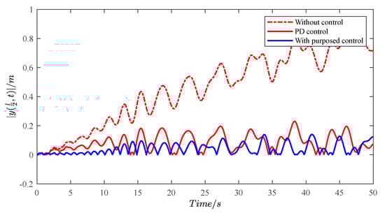
Figure 4.
Absolute value of vibration at midpoint of the umbilical cable with different controllers.
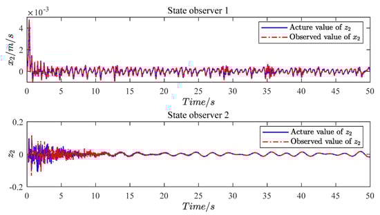
Figure 5.
The actual values and observed values of the system state values.
Then, we discuss the control effect of the proposed controller with actuator fault to verify the validity of the fault control (16). As a comparison, assume that the factor of thrust is known, so we may obtain the control angular velocity of motors without the fault control. The responses of MDRCS in the following four cases are needed.
- No actuator fault and without fault control.
- No actuator fault and fault control.
- Actuator fault and without fault control.
- Actuator fault and fault control.
In Figure 6, the controller without fault control has a better control effect because the thrust factor is known when the actuators are normal, but it may cause the system to diverge with the actuator’s fault. After that, the controller with fault control can suppress vibration in both cases. When the actuator fails suddenly, the boundary response decreases after a quick increase until it becomes stable. Furthermore, the motors’ angular velocity and voltage in both cases are shown in Figure 7 and Figure 8. The observed values and actual values of the disturbances are shown in Figure 9.
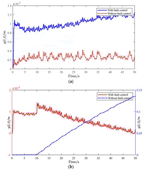
Figure 6.
The control effect of fault control. (a) With actuator fault; (b) without actuator fault.
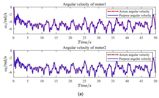
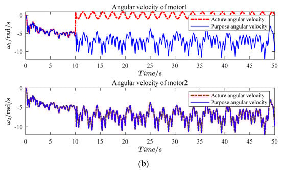
Figure 7.
The angular velocity of motors. (a) With actuator fault; (b) without actuator fault.
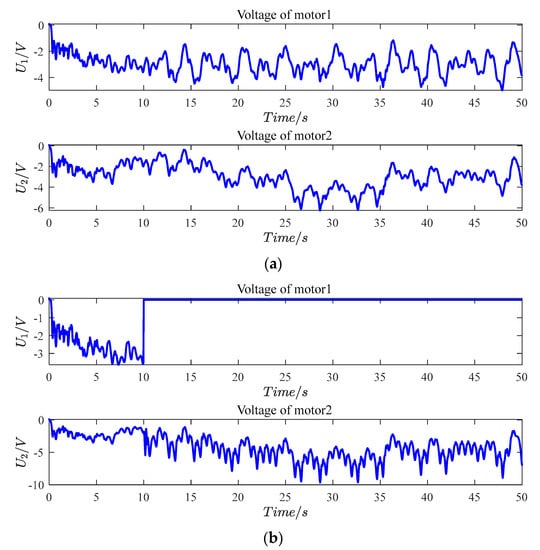
Figure 8.
The control voltage of motors. (a) With actuator fault; (b) without actuator fault.
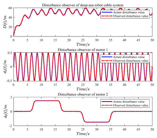
Figure 9.
Actual and observed values of the disturbances in MDRCS.
5. Conclusions
In this paper, the deep-sea robot cable system and the motor system are linked by motor rotation to provide thrust, and a cascade controller is designed for the cascade system MDRCS to suppress the boundary transverse vibration of the umbilical cable. High gain state observers, a disturbance observer, and a fault control are designed for unknown system state quantities, unknown external disturbances, and control faults respectively. In particular, the fault control can also approximate the mathematical connection between the inner and outer loops when the thrust factor is unknown. The outer controller which is designed to obtain the control thrust is an output feedback boundary controller. Because the speed control system of the motor system is non-linear, the inner controller is designed using the multiple inversion method to obtain the control motor voltage. Subsequently, the stability of the inner and outer loop system is also proved by separately using the Lyapunov method. Finally, the validity of the controller and the fault control under fault conditions are verified by numerical simulation.
Author Contributions
N.W.: Data curation, Writing—original draft, Software, Validation, Visualization, Conceptualization, Funding acquisition, Project administration. H.R.: Investigation, Validation, Methodology, Visualization, Formal analysis, Writing—review & editing. R.D.: Writing—review & editing. All authors have read and agreed to the published version of the manuscript.
Funding
This research was funded by the National Natural Science Foundation of China (Grant No. 52005373); Zhejiang Provincial Natural Science Foundation of China (Grant No. LQ21E050002); Wenzhou Municipal Science and Technology Bureau, China (Grant No. G2020014).
Institutional Review Board Statement
Not applicable.
Informed Consent Statement
Not applicable.
Data Availability Statement
Not applicable.
Conflicts of Interest
The authors declare that they have no known competing financial interests or personal relationships that could have appeared to influence the work reported in this paper.
Appendix A
Since the coupling terms exists in Equation (33) and the formula satisfies the conditions of Lemma 3, so apply the Lemma 3. We obtained the inequality
According to the absolute value inequality, we have the inequality
where and .
By choosing the reasonable values of and , the following inequality is obtained
And design the parameters of as:
Substituting the Equation (A3) into Equation (A2), we have
Finally, adding on the both sides of the Equation (A4), we obtain
where , .
Appendix B
Equation (31) is a Lyapunov function which is composed of the energy functions of the system, it is sufficient to show that the time derivative of the function is always less than zero to ensure the system is finitely stable [25]. So, derivation of a Lyapunov function to first order is
The item in the Equation (A6) is
Using the Newtonian Leibniz formula for the derivation of variable limit integrals and substituting the system Equation (10), we have
Substituting the Equation (A8) into Lemmas 2, we obtain the inequality
Similarly, the item in the Equation (A6) can be written as the following equation, finally.
Again, by the Lemmas 2, we finally have inequality
Substituting the adaptive law (27) and observers (21) into the item in the Equation (A6), we can obtain the inequality, similarly.
Finally, applying the Equations (A9), (A11), and (A12) for the Equation (A6), the inequality can be rewritten by homogeneous combination of polynomials. The following inequality has positive and negative items, and the conclusion that the time derivative of the energy function is less than zero and cannot be obtained. So, considering further deflation, the function can be written in the form of Lemma 1.
where the parameters are selected as,
The inequality is obtained by further deflating
where
According to the Lemma 1, we have
References
- Nomoto, M.; Hattori, M. A deep ROV "DOLPHIN 3K": Design and performance analysis. IEEE J. Ocean. Eng. 1986, 11, 373–391. [Google Scholar] [CrossRef]
- Bowen, A.D.; Yoerger, D.R.; Whitcomb, L.L.; Fornari, D.J. Exploring the deepest depths: Preliminary design of a novel light-tethered hybrid ROV for global science in extreme environments. Mar. Technol. Soc. J. 2004, 38, 92–101. [Google Scholar] [CrossRef]
- Bingham, B.; Mindell, D.; Wilcox, T.; Bowen, A. Integrating precision relative positioning into JASON/MEDEA ROV operations. Mar. Technol. Soc. J. 2006, 40, 87–96. [Google Scholar] [CrossRef]
- Barry, J.P.; Hashimoto, J. Revisiting the challenger deep using the ROV Kaiko. Mar. Technol. Soc. J. 2009, 43, 77–78. [Google Scholar] [CrossRef]
- Soylu, S.; Proctor, A.A.; Podhorodeski, R.P.; Bradley, C.; Buckham, B.J. Precise trajectory control for an inspection class ROV. Ocean. Eng. 2016, 111, 508–523. [Google Scholar] [CrossRef]
- Klaycham, K.; Athisakul, C.; Chucheepsakul, S. Nonlinear vibration of marine riser with large displacement. J. Mar. Sci. Tech.-Jpn. 2017, 22, 361–375. [Google Scholar] [CrossRef]
- Du, J.; Cui, C.; Bao, H.; Qiu, Y. Dynamic analysis of cable-driven parallel manipulators using a variable length finite element. J. Comput. Nonlin. Dyn. 2015, 10, 011013. [Google Scholar] [CrossRef]
- Zhu, W.D.; Ren, H. An accurate spatial discretization and substructure method with application to moving elevator cable-car systems—part I: Methodology. J. Vib. Acoust. 2013, 135, 051036. [Google Scholar] [CrossRef]
- Kanellakopulos, I. Systematic design of adaptive controllers for feedback linearizable systems. IEEE T. Automat. Contr. 1991, 36, 1241–1253. [Google Scholar] [CrossRef]
- Xian, B.; Dawson, D.M.; de Queiroz, M.S.; Chen, J. A continuous asymptotic tracking control strategy for uncertain nonlinear systems. IEEE T. Automat. Contr. 2004, 49, 1206–1211. [Google Scholar] [CrossRef]
- Rios-Bol I Var, M.; Zinober, A.; Sira-Ram I Rez, H. Dynamical adaptive sliding mode output tracking control of a class of nonlinear systems. Int. J. Robust Nonlinear Control. IFAC-Affil. J. 1997, 7, 387–405. [Google Scholar] [CrossRef]
- Wheeler, G.; Su, C.; Stepanenko, Y. A Sliding Mode Controller with Improved Adaptation Laws for the Upper Bounds on the Norm of Uncertainties. Automatica 1998, 34, 1657–1661. [Google Scholar] [CrossRef]
- Tong, S.C. Adaptive fuzzy control for uncertain nonlinear systems. J. Control. Decis. 2019, 6, 30–40. [Google Scholar] [CrossRef]
- Wang, L. Stable adaptive fuzzy control of nonlinear systems. IEEE T. Fuzzy Syst. 1993, 1, 146–155. [Google Scholar] [CrossRef]
- Abbasimoshaei, A.; Mohammadimoghaddam, M.; Kern, T.A. Adaptive fuzzy sliding mode controller design for a new hand rehabilitation robot. In Haptics: Science, Technology, Applications; EuroHaptics 2020: Leiden, The Netherlands, 2020; pp. 506–517. [Google Scholar]
- Yoo, S.J.; Park, J.B.; Choi, Y.H. Adaptive dynamic surface control of flexible-joint robots using self-recurrent wavelet neural networks. IEEE Trans. Syst. Man Cybern. Part B (Cybern.) 2006, 36, 1342–1355. [Google Scholar] [CrossRef]
- Zhao, Z.; Wang, X.; Zhang, C.; Liu, Z.; Yang, J. Neural network based boundary control of a vibrating string system with input deadzone. Neurocomputing 2018, 275, 1021–1027. [Google Scholar] [CrossRef]
- Abdollahi, F.; Talebi, H.A.; Patel, R.V. A stable neural network-based observer with application to flexible-joint manipulators. IEEE Trans. Neural Netw. 2006, 17, 118–129. [Google Scholar] [CrossRef]
- Azinheira, J.R.; Moutinho, A. Hover control of an UAV with backstepping design including input saturations. IEEE T. Contr. Syst. T. 2008, 16, 517–526. [Google Scholar] [CrossRef]
- Cai, J.; Shen, L.; Wu, F. Adaptive control of a class of non-linear systems preceded by backlash-like hysteresis. Math. Struct. Comp. Sci. 2014, 24, e240504. [Google Scholar] [CrossRef]
- Cai, J.; Wen, C.; Su, H.; Liu, Z. Robust adaptive failure compensation of hysteretic actuators for a class of uncertain nonlinear systems. IEEE T. Automat. Contr. 2013, 58, 2388–2394. [Google Scholar] [CrossRef]
- Guo, H.; Liu, Y.; Liu, G.; Li, H. Cascade control of a hydraulically driven 6-DOF parallel robot manipulator based on a sliding mode. Control Eng. Pract. 2008, 16, 1055–1068. [Google Scholar] [CrossRef]
- Khalilpour, S.A.; Khorrambakht, R.; Taghirad, H.D.; Cardou, P. Robust cascade control of a deployable cable-driven robot. Mech. Syst. Signal. Pr. 2019, 127, 513–530. [Google Scholar] [CrossRef]
- Hu, Y.; Chen, C.; Wu, H.; Song, C. Study on structural optimization design and cascade PID control of maglev actuator for active vibration isolation system. J. Vib. Control. 2018, 24, 1829–1847. [Google Scholar] [CrossRef]
- Fossen, T.I. Marine Cybernetics, Tapir Trykkeri. In Marine Control Systems—Guidance. Navigation, and Control of Ships, Rigs and Underwater Vehicles; Norwegian University of Science and Technology: Trondheim, Norway, 2002; ISBN 8292356002. [Google Scholar]
- He, W.; Ge, S.S. Vibration Control of a Flexible String With Both Boundary Input and Output Constraints. IEEE T. Contr. Syst. T. 2015, 23, 1245–1254. [Google Scholar] [CrossRef]
- Ge, S.S.; He, W.; How, B.V.E.; Choo, Y.S. Boundary Control of a Coupled Nonlinear Flexible Marine Riser. IEEE T. Contr. Syst. T. 2010, 18, 1080–1091. [Google Scholar] [CrossRef]
- Zhao, Z.; Ren, Z.; Ma, Y. Boundary control for a flexible string system with input saturation constraint. Asian J. Control. 2020, 22, 934–943. [Google Scholar] [CrossRef]
- Behtash, S. Robust output tracking for non-linear systems. Int. J. Control 1990, 51, 1381–1407. [Google Scholar] [CrossRef]
- Tayebi, A. Backstepping-based discontinuous adaptive control design for the stabilization of nonholonomic mobile robots with matched uncertainties. In Proceedings of the 36th IEEE Conference on Decision and Control, San Diego, CA, USA, 12 December 1997; Volume 4, pp. 3664–3669. [Google Scholar]


Publisher’s Note: MDPI stays neutral with regard to jurisdictional claims in published maps and institutional affiliations. |
© 2022 by the authors. Licensee MDPI, Basel, Switzerland. This article is an open access article distributed under the terms and conditions of the Creative Commons Attribution (CC BY) license (https://creativecommons.org/licenses/by/4.0/).