Article

Study on the Design and Experimental Research on a Bionic Crab Robot with Amphibious Multi-Modal Movement

1
College of Information and Communication Engineering, Harbin Engineering University, Harbin 150001, China
2
College of Mechanical and Electrical Engineering, Heilongjiang Institute of Technology, Harbin 150050, China
3
Science and Technology on Underwater Vehicle Laboratory, Harbin Engineering University, Harbin 150001, China
*
Author to whom correspondence should be addressed.
J. Mar. Sci. Eng. 2022, 10(12), 1804; https://doi.org/10.3390/jmse10121804
Submission received: 5 October 2022 / Revised: 16 November 2022 / Accepted: 21 November 2022 / Published: 22 November 2022

Abstract

:
Bionic amphibious robots are the intersection of biology and robotics; they have the advantages of environmental adaptability and maneuverability. An amphibious robot that combines walking and swimming move modes inspired by a crab (Portunus) is presented in this article. The outstanding characteristic of the robot is that its environmental adaptability relies on the bionic multi-modal movement, which is based on two modular bionic swimming legs and six modular walking legs. We designed the biomimetic crab robot based on the biological observation results. The design, analysis, and simulation of its structure and motion parameters are introduced in this paper. The swimming propulsion capability and the walking performance are verified through indoor, pool, and seaside experiments. In conclusion, the designed bionic crab robot provides a platform with practical application capabilities in amphibious environment detection, concealed reconnaissance, and aquaculture.

1. Introduction

In recent years, the shoal zone connecting the ocean and land has received more attention in scientific investigation, environmental monitoring, seabed resource survey, and development. For shoal operations, traditional subsea robots using propellers as propulsion devices are not suitable because of environmental factors such as water grass winding, sand, and gravel [1]. Therefore, amphibious robots have gradually become the focus of shoal operation robot research. According to the different driving modes of amphibious robots for shallow operation, the robots can be roughly divided into two categories: (1) a single driving mode that can move in only one mode, such as walking or jumping, and (2) a compound (hybrid) driving mode that can motion in at least two modes such as walking and swimming, even flying. Among them, the single driving mode is difficult to fulfill the requirements for robot flexibility, light mobility, and propulsion speed during water and land motion. In order to achieve high-efficiency locomotion capability in the complex amphibious environment, the development of a new type of hybrid or composite drive mechanism is gradually becoming a central issue in the field of shoal operational robots [2,3]. With the advancement of science and technology, bionic underwater propulsion technology with high efficiency, low energy consumption, and fast maneuvering as the research goal is increasingly favored by researchers.
The bionic underwater robot is developed by simulating the shape or motion characteristics of aquatic creatures with various forms [4]. Romano et al. were the first to report such complex cognitive processes in ostracods, paving the way to new research directions for Lab-on-a-Chip systems, focused on behavioral ecology and cognition studies, as well as the development of novel biohybrid sensors [5]. By testing surface and cave dwelling mollies with RoboFish, a biomimetic robot made for use in laboratory experiments with guppies and sticklebacks, Bierbach et al. asked to what extent visual and non-visual cues play a role in their social behavior [6]. A “closed-loop control” system was demonstrated by Spinello et al. to investigate the fear response of zebrafish in which the reaction of the mechanical stimulus is determined in real time through a finite state Markov chain constructed from independent observations on the interactions between zebrafish and their predators [7]. Katzschmann et al. presented the design, fabrication, control, and oceanic testing of a soft robotic fish that exhibited a lifelike undulating tail motion enabled by a soft robotic actuator design, swimming in three dimensions to continuously record the aquatic life it is following or engaging [8]. Graf et al. compared two gaits on diverse terrains (hard linoleum, soft mats, and underwater sand) to lead to a better understanding of how to use crab-like morphology for more efficient locomotion [9]. Greine et al. developed Autonomous Legged Underwater Vehicles (ALUVs) for mine hunting in the surf zone and optimized for fast [10].
Traditional underwater vehicles propelled by propellers generate noise when the propellers rotate at high speed; the noise will disturb the animals in the water and even destroy the creatures. Bionic robots are more environmentally friendly and have recently become popular with researchers. Researchers Liu and Jiang of the Harbin Institute of Technology researched the swimming style of three kinds of fish [11]. The results indicate when the fish swims with high efficiency, the curvature amplitude reaches a maximum at the caudal peduncle. Their study provides a reference for curvature control of bionic fish. Donghua University researchers designed a robotic fish that can propel and maneuver in any direction that could be realized by changing the orientation of the spatial oscillating rigid caudal fin [12]. The conceptual prototype learns to maneuver in any order by changing the direction of the caudal fin. Zhejiang University and Northwestern Polytechnical University researchers built their biomimetic manta ray underwater robots. All their biomimetic manta ray underwater robots can swim similar to manta rays [13,14,15]. This method of propulsion has the advantages of propulsion efficiency and maneuverability. However, neither of the robots can reach the biological manta rays’ speed in the water. In addition, there are studies on non-fish-like underwater vehicles. Dong, Bi, and Liu of Peking University research the behaviors of Solen strictus Gould that use their axe feet to dig caves and escape-swimming when food and environment change [16]. This study is of great significance in underwater jet propulsion types of underwater bionic robots.
Among the various bionic robots, the bionic multi-legged robot possesses high flexibility and obstacle-crossing solid ability, and it has become a hot spot for global scholars. After decades of research, all multi-legged bionic robots have been developed worldwide and applied to various fields [17,18,19,20]. Compared with the biomimetic underwater robots propelled by fins and tail undulatory propulsors [21,22,23], the legged robot usually has better load capacity and benthic capacity in the amphibious environment. The German Aerospace Center (DLR) developed the tandem hexapod robot DLR-Crawler with 18 degrees of freedom totally and walking feet with perceptual ability [24]. The robot’s attitude can be adjusted in real-time to adapt to the complex terrain environment by receiving the force transmitted by the sensor on foot as feedback information. The British company Nekton Research designed a series of turtle-shaped quadruped robots named Madeleine by imitating the sea turtle’s traveling method based on bionic principles [25]. The robot is equipped with a pair of turtle feet as its motion mechanism on the left and right sides, and a high-power motor is installed to overcome the weakness of low walking speed. Harbin Institute of Technology Robot Technology and State Key Laboratory took stick insects as a bionic prototype to develop a tandem hexapod robot HITCR-II [26]. Each leg of the robot is equipped with three rotating joints driven by motors, and six legs are symmetrically and evenly distributed on both sides of the body. The robot can smoothly pass through complex terrain during the walking process, which improves the robot’s motion stability and maneuverability.
Most of the extant amphibious bionic multi-legged robots also lack breakthroughs in underwater movement due to their single propulsion mode and poor environmental adaptability. Therefore, finding an aquatic creature with compound propulsion and multiple motion modes as a bionic object is meaningful. The Portunus is a shoal crab with superior underwater locomotion capability; they crawl on the sea floor with the first three pairs of walking legs and swim with the last two swimming legs. The creature possesses three propulsion methods: land walking, seabed crawling, and underwater swimming resulting in excellent adaptability to ocean waves and currents. Therefore, Portunus widely exists in the shoal, surge, and other environments [27]. Many researchers in the field of robotics have already studied crabs and developed a variety of crab robots [9,28,29,30]. We have learned one kind of the walking gait of Portunus and demonstrated its viability in the amphibious environment with a simple robotic platform [31]. Previous studies on crabs have primarily focused on their walking behavior, and we found that when swimming with the two swimming legs, all leg joints reciprocate rather than rotate continuously, which significantly reduces the risk of entanglement by organisms such as aquatic plants during propeller propulsion. We believe this type of swimming mode is valuable for developing underwater and amphibious robots and deserves to be studied.
This paper takes the Portunus as a bionic prototype and applies its underwater propulsion mechanism to the field of legged robots. Observation and digital representation of the movement of the swimming leg of Portunus trituberculatus as it swims. Its behavior is analyzed by hydrodynamic theory and simulation. Its swimming ability is verified by developing a robotic platform and experiments in the amphibious environment, which not only provides a scientific explanation of the swimming process of Portunus but also provides a feasible swimming method for amphibious robots and underwater robots. Combined with the unique underwater motion method of the Portunus, the underwater propulsion mechanism and motion control of the amphibious bionic multi-legged robot were studied. The remaining article is structured as follows. In Section 2, we build a motion observation, image recognition, and data processing platform to observe and digitally represent the swimming process of crabs, and a typical swimming pattern is obtained. In Section 3, we design and make a bionic crab robot. The robot’s analysis, modeling, and simulation are also studied in this section. In Section 4, the performance evaluation experiment is shown, and the abilities achieved by the crab robot are presented, along with the performance indicators. Finally, in Section 5, the conclusions of this article and our future work are presented.

2. Biological Observation

To completely understand the crab’s movement behavior, we need to build a motion capture platform to accurately observe the crab’s movement process and digitally represent its movement behavior. Designing a crab robot based on the behavioral requirements of crab movement is reasonable.

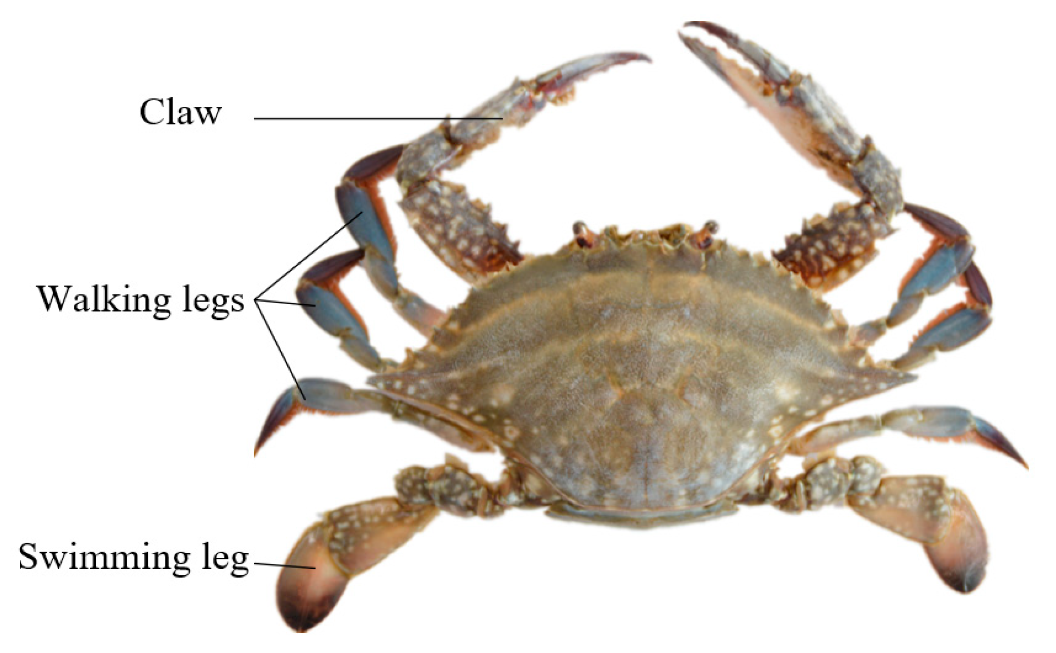
2.1. Crab (Portunus trituberculatus)

For a robot operating in a place with a shoal, land walking, seabed crawling, and underwater swimming are necessary. Crabs are amphibian, crustacean, and theropodan, which are good archetypes of robots for operation on beaches and shoals. A crab (Portunus) is shown in Figure 1. It is composed of a shell, two claws in front, two swimming legs behind, and three walking legs on each side in the middle, and they are all symmetric, as shown in Figure 1. This construction makes it good at crawling laterally (left/right) and swimming forward.

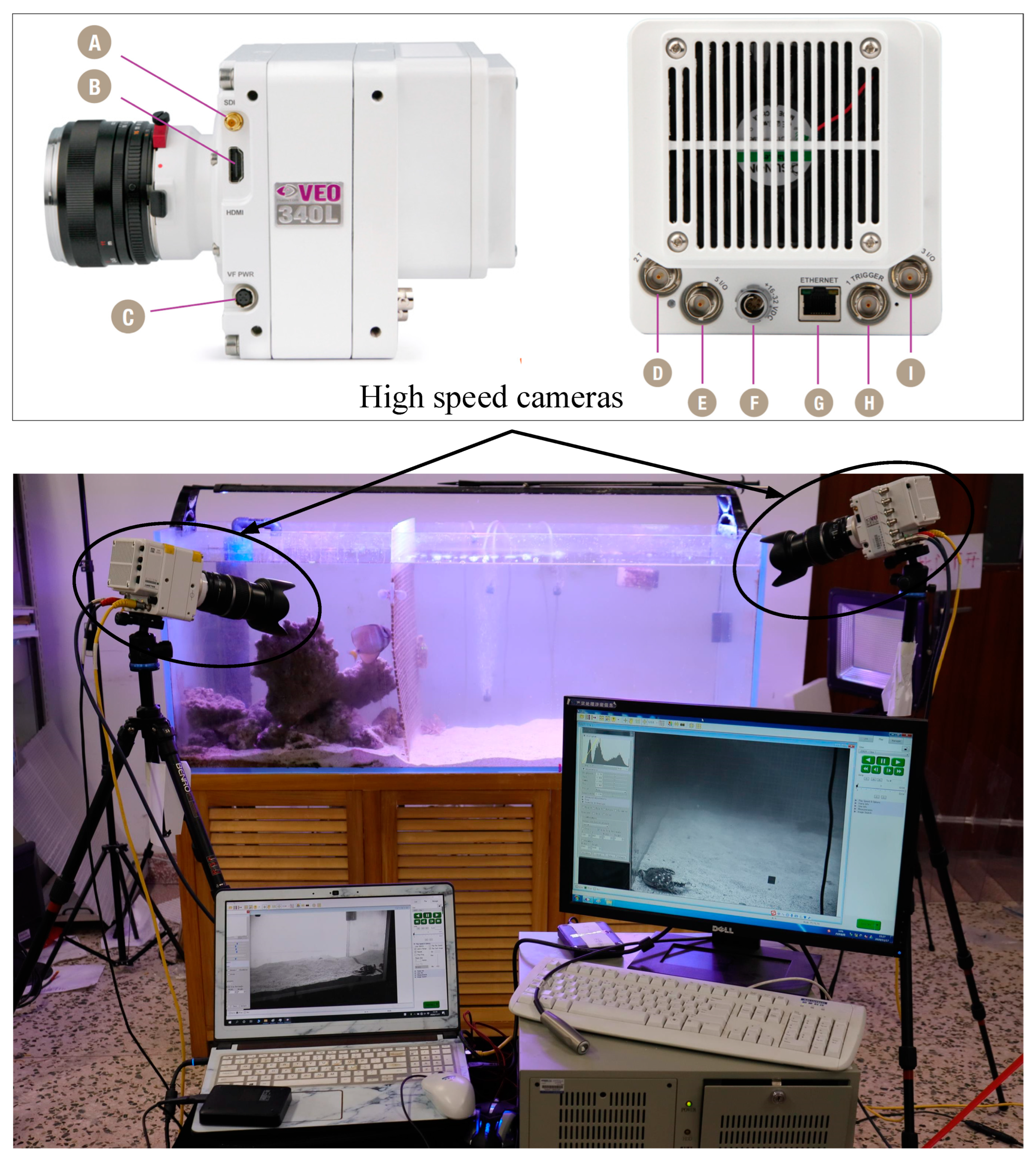
2.2. Observation Platform

As shown in Figure 2, we built the observation platform to observe and study the swimming motion process of crabs. The observation platform comprises an observation tank and a set (two) of high-speed cameras arranged orthogonally. The size of the observation tank is 1500 mm × 600 mm × 600 mm, and the length of the observation tank is more than 20 times the average body width of the crabs used for observation to ensure that the crabs can complete a complete motion cycle in the observation tank. The body size of sea crabs was obtained by measuring the body shape of 16 sea crabs (mean value of 71.32 mm, variance of 3.4278 mm). Two orthogonally arranged high-speed cameras (Phantom VEO/VEO4K-L) were used to capture images of the sea crab’s motion from different directions.

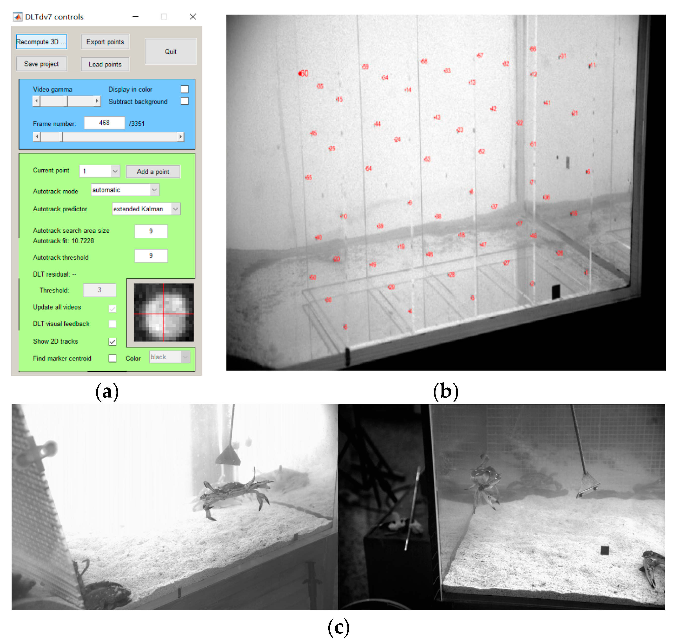
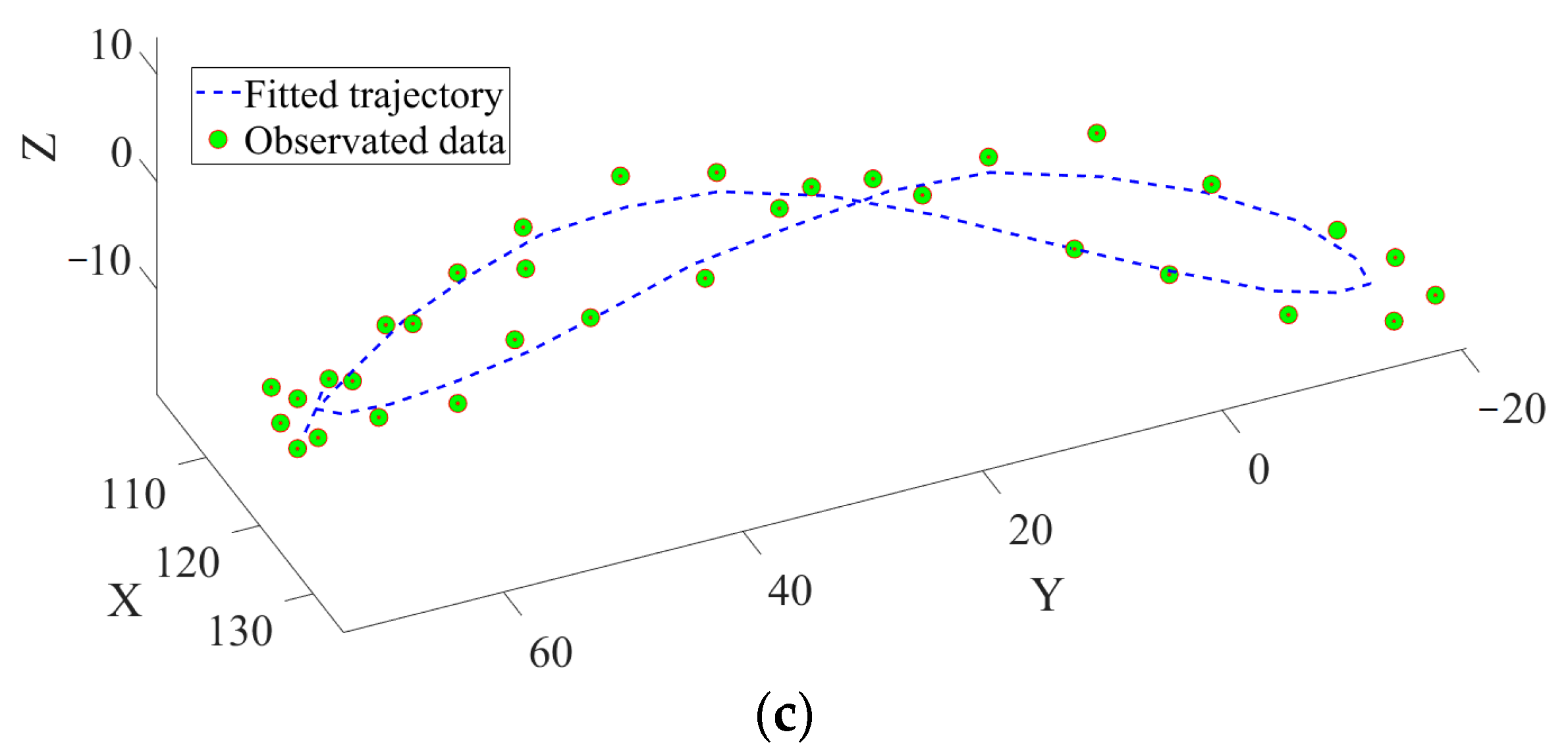
2.3. Three-Dimensional Kinematics Capture

We use direct linear transformation (DLT) [32,33,34] to obtain detailed three-dimensional (3-D) kinematics of crab locomotion. DLT is a technique well-established and widely used in animal studies. DLT is essentially an algorithm to transform two-dimensional (2-D) coordinates of the object of interest in multiple camera views into three-dimensional (3-D) coordinates.
We use a freely available software package, DLTcal7 and DLTdv7 (courtesy of TyHedrick [26]) (Figure 3a). We custom-made a 60-point calibration object using an acrylic frame (Figure 3b). By placing the calibration object in the field of view of two (or more) securely mounted high-speed cameras, we can obtain still calibration images which yield transformation matrix (via DLTcal7). We can then take a simultaneous high-speed video of animals (or robots) of interest moving in the field of view using two (or more) cameras and digitizing the markers on the animals (or robots) in 2-D videos (Figure 3c), then transforming them into 3-D coordinates (via DLTdv7) yield 3-D kinematics. This technique can provide sub-millimeter accuracy for a 200 mm ×200 mm field of view.

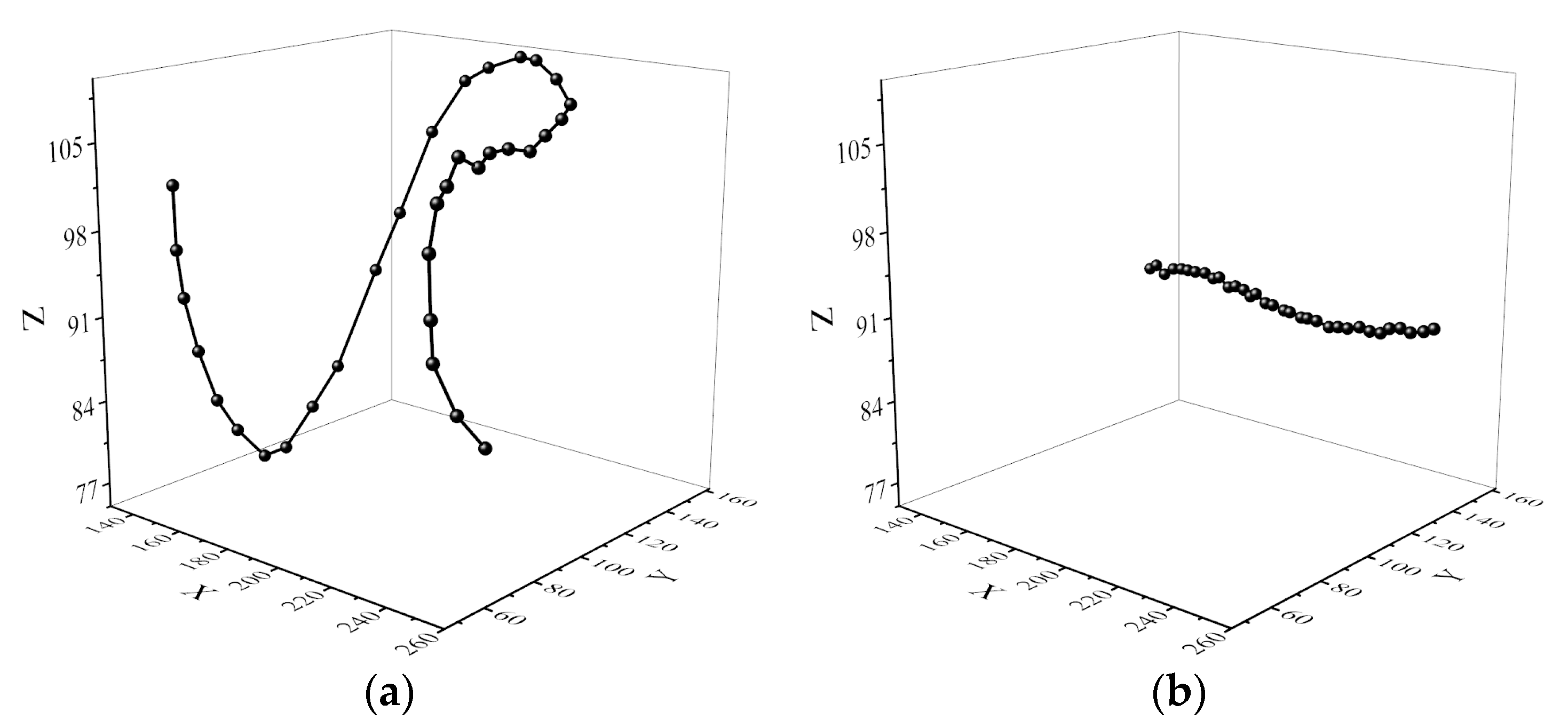
2.4. Kinematics Data

The swimming leg’s gait of a crab was captured through biological observation. A kinematics data example is shown in Figure 4a, which is the trajectory of the toes (the ends of the swimming legs) of the crab during the swimming process, and Figure 4b is the trajectory of the center of the crab’s shell during the swimming process. The trajectory coordinate of the toe minus the trajectory coordinate of the shell’s center is the movement trajectory of the toe relative to the body, as shown in Figure 4c, which is a three-dimensional trajectory in an approximate “8” shape.
According to the biological observation results, the swimming legs of the crab robot need at least three degrees of freedom (DOF) to realize the trajectory motion of the toe during the crab’s swimming process. For the walking legs, at least three DOF are also required for lateral walking and turning functions.

3. The Design of the Crab Robot

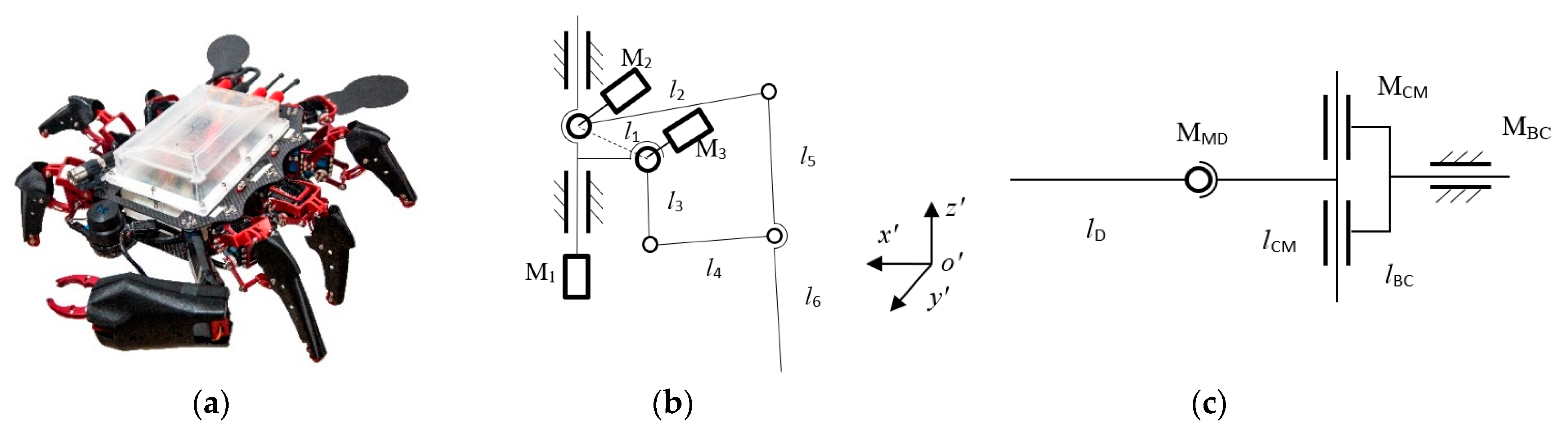
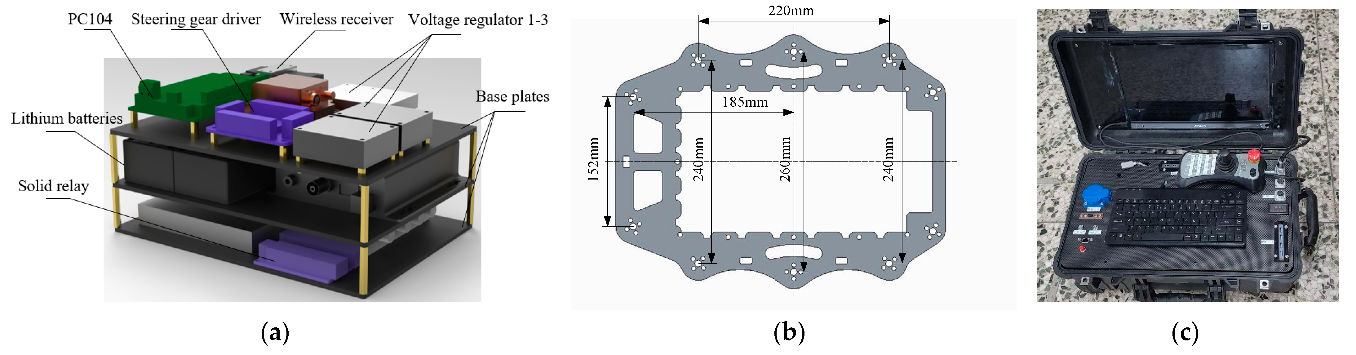
3.1. The Structure Design

The crab robot is shown in Figure 5. Walking legs and a link mechanism with 3-DOF (Figure 5b) were designed for the motion and load of the leg and joint of the robotic crab. Three servo-steering gears were integrated into a steering gear unit. One steering gear, M1, was applied on joint one rotating around z in the range of (−90°, +90°). The other two steering gears, M2 and M3, are applied on joints 2 and 3, rotating around x to drive the 5-link mechanism to move the foot tip back and forth or up and down in the ranges of (−30°, +30°) and (−60°, +60°) respectively in the leg coordinates system of oxyz.
The swimming leg is shown in Figure 5c. The motored joint BC rotated about the axis of y, CM about the z, and MD about the axis of x in the leg coordinate system of oxyz, which was perpendicular to each other.
The control module was composed of a steering gear driver and a central controller. The steering gear driver used was Arduino USB with 32 channels. 22 channels were used and 10 channels for redundancy. The central controller was PC104 with interfaces of USB, PS/2, serial, parallel, PC104 bus, and Ethernet. A wireless receiver was installed for the remote control. The power unit was composed of two lithium batteries with the power of 100 w, solid relays 1 and 2, voltage regulators 1–3, and base plates. One lithium battery output was 7 V to drive steering gears, and another was 12 V for the control system. Voltage regulator 1 output was 5 V, for the steering gear driver, see the control module; voltage regulator 2 output was 5 V for driving steering gears, and regulator 3 output was 12 V for the control system. The three-dimensional overall model of the control module and power unit is shown in Figure 6a. The implementation details in Figure 6 are shown in the Supplementary Material Table S1.
Two fiber plastic frame boards, 3 mm in thickness, were separated by 6 aluminum posts. The frame board was shown in Figure 6b. Three legs were arranged on each side symmetrically keeping an angle of 45° with each other. Two swimming legs were fitted in the end symmetrically keeping an angle of 90° with each other. The control module and power unit were mounted on the two frame boards, as shown in Figure 5. In the initial state, the robotic crab setup was as shown in Figure 5, and the profile was 0.66 m in length, 0.49 m in width, and 0.38 m in height. The mass of the robotic crab assembly was 6.5 kg in total, and the buoyancy was 42 N in water. We can adjust the buoyancy of the robot by manually adding or removing buoyancy blocks. A control platform is configured for the robot, as shown in Figure 6c.

3.2. Analyzing and Modeling for Walking Leg

The kinematic model of the walking leg was established by the D-H method. As shown in Figure 7, the D-H coordinate system of the serial manipulator composed of AB and BP is based. The established coordinate system follows the right-hand rule.
The D-H parameters of the walking leg are shown in Table 1. l1, l2, and l are the lengths of each link of the walking leg. θ 1 , θ 2 , and θ 3 are the rotation angles of each joint. q 1 = θ 1 , q 2 = θ 2 − π/2, q 3 = π/2 + r 2 θ 2 , are the angular displacements of each joint, respectively.
Let (Px, Py, Pz) be the coordinates of the walking foot of the multi-legged robot in the reference coordinate system, then there is a D-H coordinate system transformation matrix as shown in (1).
T 4 0 = T 1 0 T 2 1 T 3 2 T 4 3 = c q 1 c q 2 + q 3 c q 1 c q 2 + q 3 s q 1 P x c q 1 c q 2 + q 3 c q 1 c q 2 + q 3 c q 1 P y s q 2 + q 3 s q 2 + q 3 0 P z 0 0 0 1
where s and c is sin and cos, respectively. So, the position of the walking leg endpoint in the reference coordinate system is:
P x = l 2 sin θ 2 + l 5 + l 6 cos γ 2 cos θ 1 P y = l 2 sin θ 2 + l 5 + l 6 sin γ 2 cos θ 1 P z = l 2 cos θ 2 + l 5 + l 6 cos 2 θ 2 γ 2
According to the kinematic model of the walking leg, the relationship between the coordinates of the endpoints of the leg and the angles of each joint can be obtained to realize the motion control of the walking process.

3.3. Analyzing and Modeling for Swimming Leg

The swimming legs are simplified as a three-joint rigid hydrofoil with three rotational degrees of freedom, as shown in Figure 5c. The swimming leg’s length is 180 mm, and the width is 100 mm. Referring to the flapping mode of fish pectoral fins, the flapping method of each rotating joint of the swimming legs can be described as:
φ F E = φ F E C φ F E C cos ω · t φ L = φ L C φ L A cos ω · t + Δ φ L φ F L = φ F L C φ F L A cos ω · t + Δ φ F L
As (3) shows that φ F E C , φ L C , φ F E C respectively refer to the mean motion angle of the swinging wing, front and rear flapping wing, and upper and lower flapping wing. φ F E A , φ L A , φ F L A respectively refer to the amplitude of the motion angle of the swinging wing, fore and aft flapping wing, and up and down the flapping wing. Δ φ L is the phase difference between the motion of the swinging wing and that of the flapping wing. Δ φ F L is the phase difference between the motion of the swinging wing and the flapping wing, ω is the change speed of each joint angle, f is the change frequency of joint angle.
According to the biological observation results, we can determine the flapping parameters of robot swimming legs in (3), as shown in Table 2. The flapping trajectory of the toe with these parameters is consistent with biological observation results.
Figure 8 shows the pressure and vorticity contour of the swimming legs in single-cycle motion. Between 0~T/4, the swimming legs flap downward. Vortex is gradually generated and accumulates on the surface of the swimming legs as they move; the high-pressure area on the upstream surface and the low-pressure site on the downstream surface increase. The forward side thrust caused by the pressure difference gradually increases to a positive peak at a specific time near T/4. Between T/4~2T/4, the vortices attached to the swimming leg surface slowly fall off, the high-pressure area on the upstream surface and the low-pressure area on the downstream surface decrease, and the forward side thrust caused by the pressure difference gradually decreases to a point near T/2 when it reaches a negative peak with the lift. Between 2T/4~3T/4, the swimming leg flapped upward from the lower limit position, and new vortices were gradually generated and accumulated on its surface. The high-pressure area on the upstream surface and the low-pressure area on the downstream surface increased, and the forward side thrust caused by the pressure difference gradually increased to reach a positive peak at some time near 3T/4. Between 3T/4~T, the vortices attached to the swimming leg surface slowly fall off, the high-pressure area on the upstream surface and the low-pressure area on the downstream surface decrease, and the positive side thrust caused by the pressure difference gradually decreases to a negative peak at some time near T, and the swimming leg moves to the upper limit position to complete a cycle of motion.

4. Experiment

To verify the walking and swimming performance of the biomimetic crab robot, we conducted experiments in the indoor experiment site, the pool, and the natural environment.

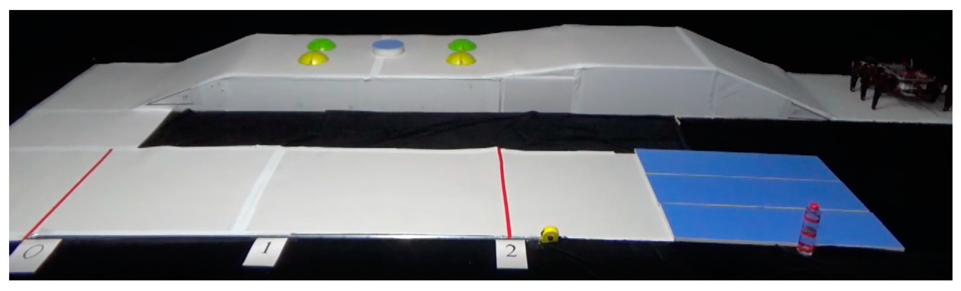
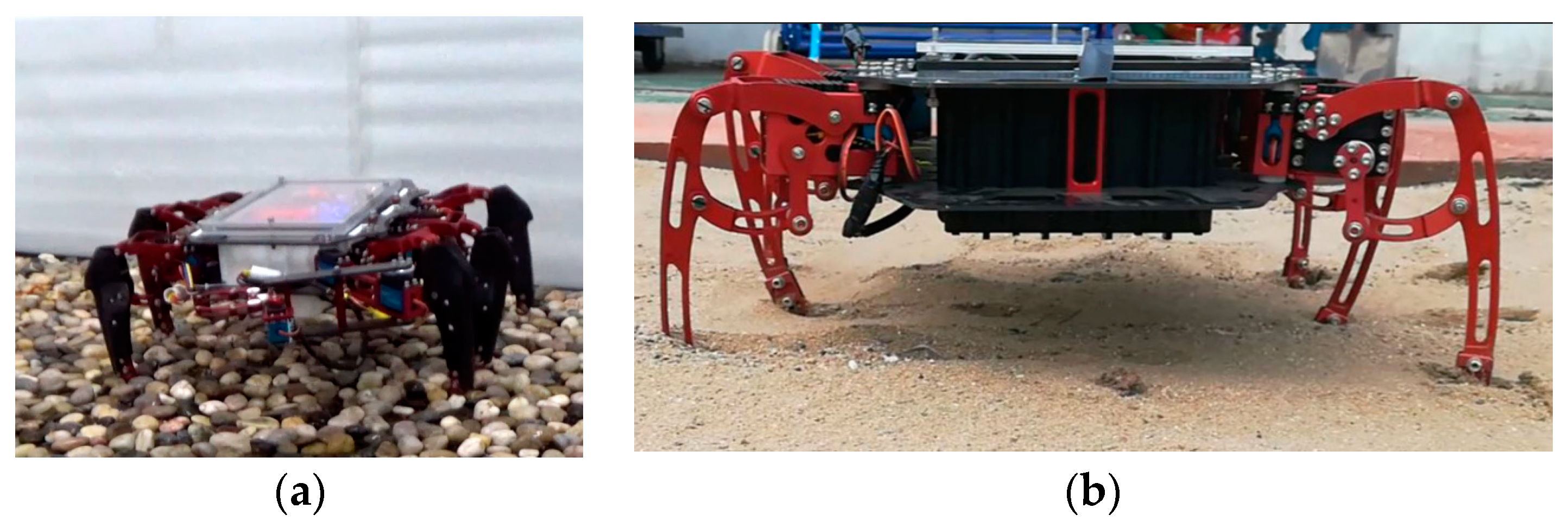
4.1. Walking Experiments

We built a walking experiment site indoors as shown in Figure 9. Including a 20° slope (used to verify the robot’s grade ability), 4 spherical obstacles with a diameter of 200 mm and a height of 50 mm, and a cylindrical obstacle with a diameter of 200 mm and a height of 50 mm (used to verify the robot’s obstacle crossing ability), a 2000 mm long straight runway (to verify the robot’s straight-line walking speed), and a 300 g object (to verify the robot’s grasping ability). The crab robot successfully passed all challenges of the indoor experiment site.
We built gravel ground and sand ground that are common in amphibious environments, as shown in Figure 10. The gravel diameter is more than 30 mm. The crab robot passed the walking experiment on gravel ground and sand ground. The walking leg will trample to a certain depth on the sand ground, but it can still walk smoothly, which also shows the advantages of the legged robot in environmental adaptability.
The underwater walking ability of the crab robot is verified in a comprehensive experimental pool. Figure 11a shows the experiment of the underwater walking speed at a depth of 3 m. The robot takes 22 s to pass a distance of 3 m, and the walking speed is about 0.14 m/s. Figure 11b shows the experiment of the underwater working depth, the experiment result shows that the robot can work at a depth of 10 m.
The walking ability of the crab robot in a real amphibious environment in the sea was verified as shown in Figure 12. The walking experiment of the robot on the wet sand ground rushed by seawater is shown in Figure 12a, the experiment result is close to the result of the simulated sand ground. The walking leg will trample into a certain depth on the sand ground, but the walking ability is hardly affected. Figure 12b shows the robot walking experiment on the sandy ground on the seabed. The impact of the water flow will cause greater disturbance to the robot, a strong impact will cause the walking leg of the robot to leave the ground for a short time, resulting in a serious loss of walking speed.

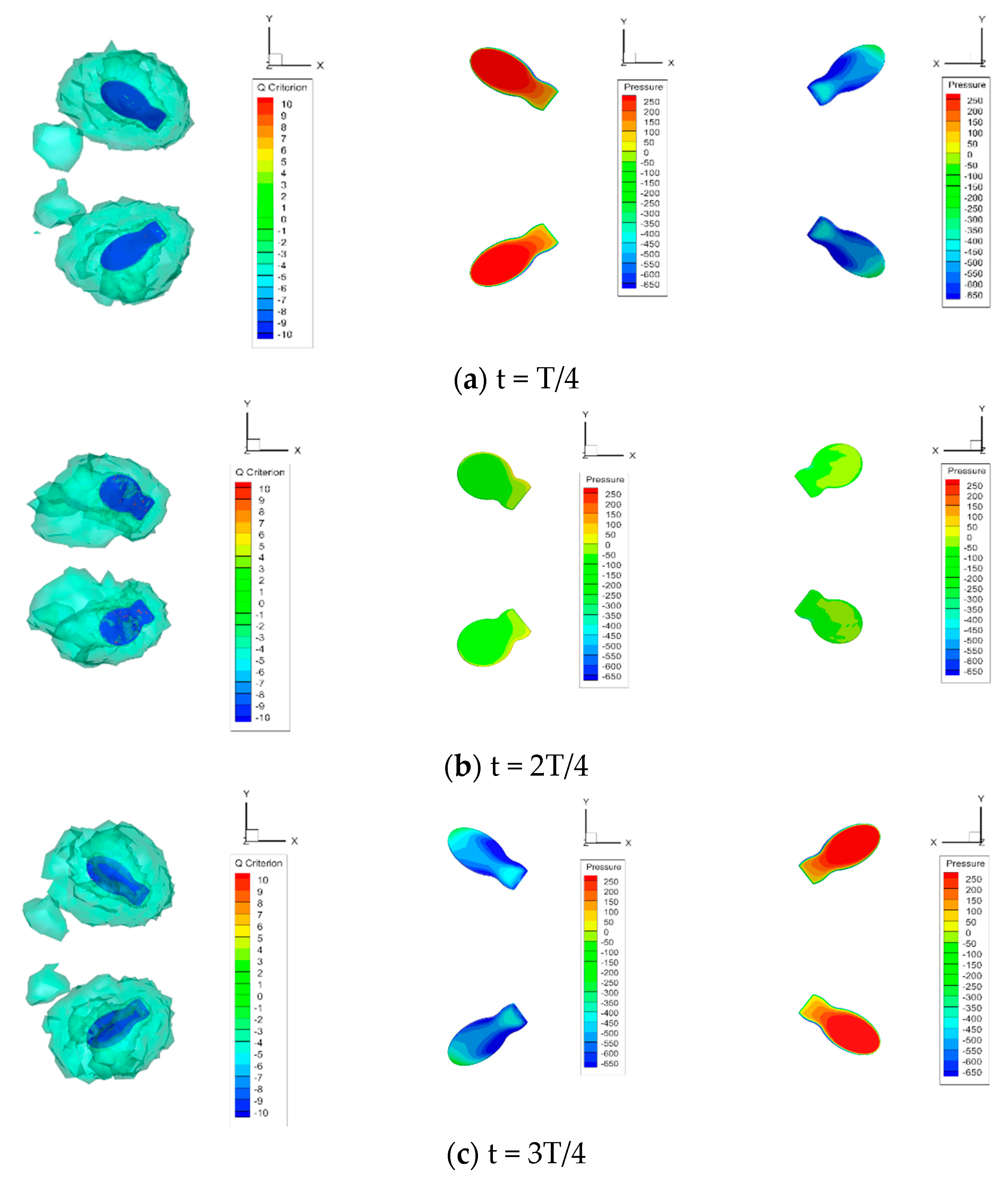
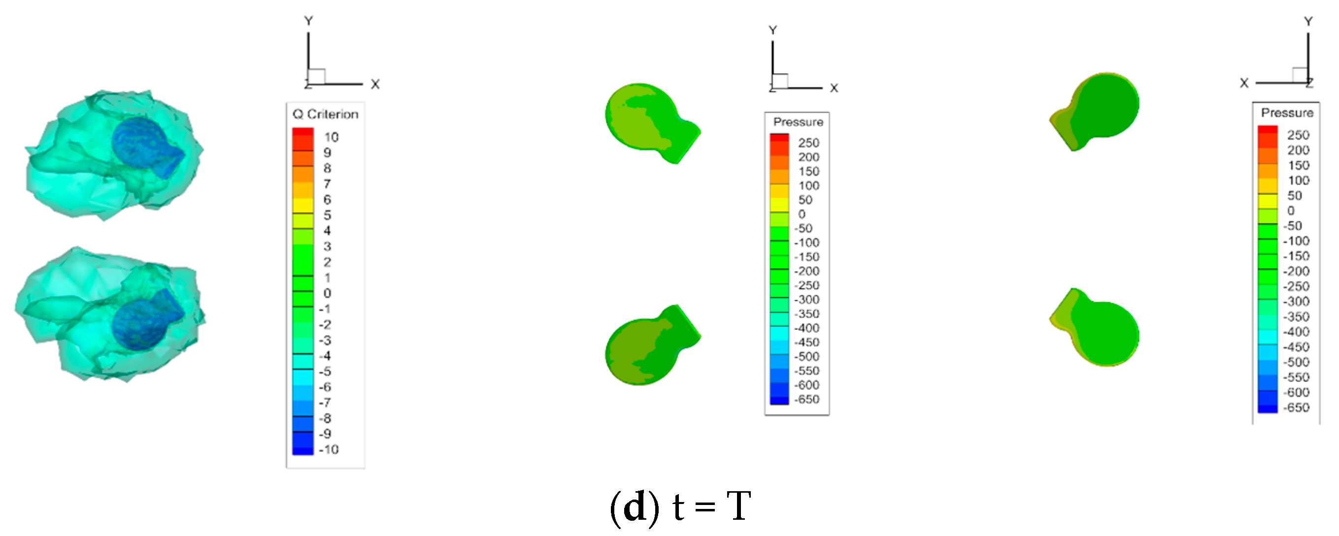
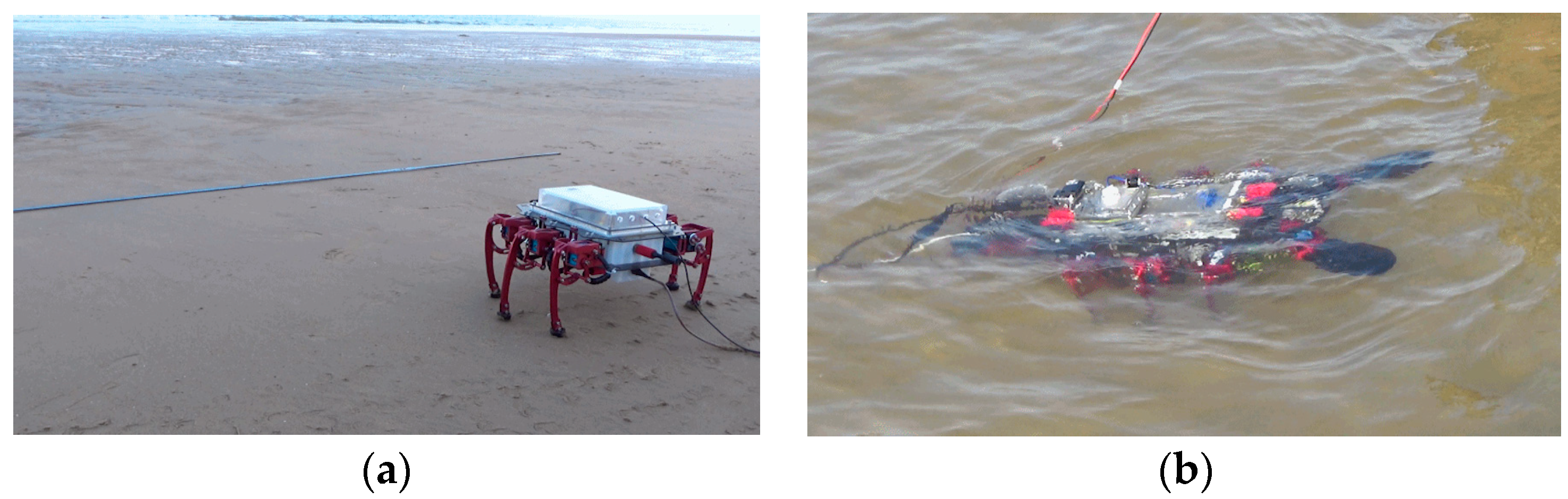
4.2. Swimming Experiments

We designed two swimming gaits for the crab robot, two swimming legs flapping simultaneously (gait 1) and flapping alternately (gait 2), and verified the swimming abilities of the two gaits in an experimental pool. Two swimming legs flapping simultaneously is shown in Figure 13a, the pitch angle of the robot changes greater than gait 2 during the swimming process. Two swimming legs flapping alternately is shown in Figure 13b, the pitch angle of the robot changes lower than gait 1 during the swimming process, but the roll angle is larger.
We conducted the experimental research on two main motion parameters under the swimming gait (including gait 1 and gait 2), including the flapping frequency of the swimming leg, f = 0.5 Hz~2.0 Hz, and the flapping amplitude (FLA), φ F L A = 20°~80°.
The experimental results of gait 1 are shown in Figure 14. The robot moves forward with a certain size of pitch angle, and due to the superposition of the double swimming leg force, the body has a lifting and sinking motion. Figure 14a shows the effect of FLA on the pitch angle. In the low-frequency range f = 0.5 Hz~0.75 Hz, θ increases with the increase in φ F L A . In the middle-frequency range f = 1.0 Hz~1.25 Hz, θ increases first and then remains unchanged. In the high-frequency range f = 1.5 Hz~2.0 Hz, θ changes less than 1°, and in Figure 14b, θ decreases with the increase in f.
The reason is that the body has enough time to reach the specified pitch angle when swimming at low frequency, and as the frequency increases, the longitudinal tilt moment direction changes faster, the robot is too late to reach the specified angle, and the effect of f is stronger than the effect of FLA at this time. Compared with Figure 14c, the simulation curve also shows a decreasing trend with frequency. f = 0.5 Hz~0.75 Hz, the actual value of the pitch angle is 2° smaller than the simulation result, and when f > 0.75 Hz, the decreasing trend of the actual pitch angle with f is larger than the decreasing trend of the simulation curve, especially when φ F L A = 40°~80°. When φ F L A = 20°~30°, the value and the change rate of simulated and experiments are the same, which means that the higher the f, the smaller the pitch angle of the body and the more stable the swimming.
The experimental results of gait 2 are shown in Figure 15, which shows that the robot swims forward with a certain size roll angle. The lift force of two swimming legs in gait 2 cancels out, and the lifting and sinking motion of the body is smaller than in gait 1. Figure 15a,b show the corresponding curves of the roll angle with FLA and f and the same trend of the overall change with pitch angle. Figure 15c shows the simulation results of the effect of f on the roll angle. By comparing the experimental and simulation results, the experiment result of the roll angle is 2–4° smaller than the simulation result when f = 0.5 Hz~0.75 Hz. When f > 0.75 Hz and φ F L A = 50°~70°, the maximum reduction rate of the experiment results in roll angle is 30 °/Hz, and the maximum reduction rate of the simulation result is 8 °/Hz. When f = 2.0 Hz, the experiment roll angle is concentrated at 2–6° at each FLA range.
The swimming speed of gait 1 and gait 2 at the flapping frequency of 1.0 Hz at each FLA is compared, as shown in Table 3. The comparison experiment was conducted in an indoor water tank, as shown in Figure 16. According to the experiment results, it can be seen that both gaits can keep the swimming direction better during the swimming process, and the swimming trajectory is approximately a straight line. The swimming speed of gait 1 is smaller than that of gait 2. When φ F L A = 20°~60°, the difference in swimming speed is evident. It is because with the increase of FLA, the pitch angle of gait 1 increases, which is equivalent to the rise of the robot’s head-on area, the resistance increases, and the swimming speed decreases. When φ F L A = 70°~80°, the pitch angle no longer increases, and the swim speed difference decreases.
All the experiments verified that the crab robot performed well in walking and swimming motion. The motion performance indexes of the crab robot are shown in Table 4. When the robot swims in the water, the buoyancy is equal to the gravity, and the net buoyancy of the robot in the water is 0 N. When the robot walks under the water, the buoyancy is 42 N, and the net buoyancy of the robot is 23 N in the vertically downward direction. In the current stage, we adjust the robot’s buoyancy by manually adding or removing buoyancy blocks.

5. Conclusions and Future Work

In this paper, we built a motion observation, image recognition, and data processing platform to observe and digitally represent the swimming process of crabs. The crab robot and the corresponding swimming gait are designed by the observing result. We analyzed, modeled, and simulated the robot. The robot’s swimming and walking abilities were verified through indoor, pool, and seaside experiments. The conclusions are as follows:
  • A typical swimming pattern was obtained by observing and digitizing the swimming process of crabs. According to the observation results, two swimming gaits are designed for the crab robot, which has advantages in swimming speed and stability respectively.
  • A bionic crab robot with multi-modal motion capability is proposed, and the motion capability is verified in a variety of typical amphibious environments.
This paper provides a motion method and a bionic crab robot platform with practical application capabilities in amphibious environment detection, concealed reconnaissance, and aquaculture.
However, there are still many problems to be solved regarding the motion of crabs in the amphibious environment. For example, how walking legs and swimming legs cooperate during running and swimming. At present, it seems that the propulsion efficiency of this flap swimming method is lower than that of traditional propellers. How to improve its propulsion efficiency is also a problem that we need to solve further. Finally, when one or more DOF of the swimming leg fails, how the robot swims or motion is an important point that needs to be solved.
In future work, we will (1) conduct in-depth research on the cooperate methods of the walking legs and swimming legs. (2) Study the methods to improve propulsion efficiency. (3) Research the swim method when one or more DOF of the swimming leg fails. (4) We will focus on the point that intends to improve energy autonomy in the robot for prolonged tasks, the swimming legs move reciprocally under the impact of the waves, thus driving the power generator to replenish the robot’s energy.

Supplementary Materials

The following supporting information can be downloaded at: https://www.mdpi.com/article/10.3390/jmse10121804/s1. Video S1 and S2: The video of the biological observation. Video S3: The video of the swimming experiment in Figure 13e,f. Video S4 and S5: The videos of the comparison experiment in Figure 16. Table S1: The implementation details in Figure 6.

Author Contributions

Conceptualization, X.C., X.M. and G.W.; methodology, X.M.; software, X.C., S.H. (Songjie Han), J.L. and K.L.; validation, X.M. and S.H. (Shihao Hu); formal analysis, X.M.; investigation, X.C. and X.M.; resources, X.C. and G.W.; data curation, X.M. and G.W.; writing—original draft preparation, X.M., S.H. (Songjie Han), B.P. and J.W.; writing—review and editing, G.W. and X.C.; visualization, X.M.; supervision, X.C. and G.W.; project administration, X.M.; funding acquisition, X.C. and G.W. All authors have read and agreed to the published version of the manuscript.

Funding

This work was funded by The National Natural Science Foundation of China (Grant No. 52001116), The National Natural Science Foundation of Heilongjiang Province (Grant No. YQ2020E033 and YQ2020E028), in part by The China Postdoctoral Science Foundation funded project under Grant 2018M630343, The Heilongjiang Postdoctoral Science Foundation funded project under Grant 18649, and The Research Fund from Science and Technology on Underwater Vehicle Technology under Grant 2021-SYSJJ-LB06909. Fundamental Research Funds of Heilongjiang Institute of Technology under Grant 2019CX07.

Data Availability Statement

All data included in this study are available upon request by contact with the corresponding author.

Conflicts of Interest

The authors declare no conflict of interest.

References

  1. Georgiades, C.; Nahon, M.; Buehler, M. Simulation of an underwater hexapod robot. Ocean Eng. 2009, 36, 39–47. [Google Scholar] [CrossRef]
  2. Jun, B.H.; Shim, H.; Kim, B.; Park, J.Y.; Baek, H.; Lee, P.M.; Kim, W.J.; Park, Y.S. Preliminary Design of the Multi-Legged Underwater Walking Robot CR200. In Proceedings of the OCEANS MTS/IEEE Conference, Yeosu, Korea, 21–24 May 2012. [Google Scholar]
  3. Ayers, J. Underwater walking. Arthropod Struct. Dev. 2004, 33, 347–360. [Google Scholar] [CrossRef] [PubMed]
  4. Ren, K.; Yu, J.C. Research status of bionic amphibious robots: A review. Ocean Eng. 2021, 227, 108862. [Google Scholar] [CrossRef]
  5. Romano, D.; Rossetti, G.; Stefanini, C. Learning on a chip: Towards the development of trainable biohybrid sensors by investigating cognitive processes in non-marine Ostracoda via a miniaturised analytical system. Biosyst. Eng. 2022, 213, 162–174. [Google Scholar] [CrossRef]
  6. Bierbach, D.; Lukas, J.; Bergmann, A.; Elsner, K.; Hoehne, L.; Weber, C.; Weimar, N.; Arias-Rodriguez, L.; Moenck, H.J.; Hai, N.; et al. Insights into the Social Behavior of Surface and Cave-Dwelling Fish (Poecilia mexicana) in Light and Darkness through the Use of a Biomimetic Robot. Front. Robot. AI 2018, 5, 3. [Google Scholar] [CrossRef] [PubMed]
  7. Spinello, C.; Yang, Y.; Macri, S.; Porfiri, M. Zebrafish Adjust Their Behavior in Response to an Interactive Robotic Predator. Front. Robot. AI 2019, 6, 38. [Google Scholar] [CrossRef] [PubMed] [Green Version]
  8. Katzschmann, R.K.; DelPreto, J.; MacCurdy, R.; Rus, D. Exploration of underwater life with an acoustically controlled soft robotic fish. Sci. Robot. 2018, 3, eaar3449. [Google Scholar] [CrossRef] [Green Version]
  9. Graf, N.M.; Grezmak, J.E.; Daltorio, K.A. Get a grip: Inward dactyl motions improve efficiency of sideways-walking gait for an amphibious crab-like robot. Bioinspir. Biomim. 2022, 17, 066008. [Google Scholar] [CrossRef]
  10. Greiner, H.; Shectman, A.; Won, C.; Elsley, R.; Beith, P. Autonomous Legged Underwater Vehicles for Near Land Warfare. In Proceedings of the Symposium on Autonomous Underwater Vehicle Technology, Monterey, CA, USA, 2–6 June 1996; pp. 41–48. [Google Scholar]
  11. Liu, Y.W.; Jiang, H.Z. Optimum Curvature Characteristics of Body/Caudal Fin Locomotion. J. Mar. Sci. Eng. 2021, 9, 537. [Google Scholar] [CrossRef]
  12. Wang, S.Y.; Han, Y.; Mao, S.T. Innovation Concept Model and Prototype Validation of Robotic Fish with a Spatial Oscillating Rigid Caudal Fin. J. Mar. Sci. Eng. 2021, 9, 435. [Google Scholar] [CrossRef]
  13. Liu, Q.M.; Chen, H.; Wang, Z.H.; He, Q.; Chen, L.K.; Li, W.K.; Li, R.P.; Cui, W.C. A Manta Ray Robot with Soft Material Based Flapping Wing. J. Mar. Sci. Eng. 2022, 10, 962. [Google Scholar] [CrossRef]
  14. Zhang, D.L.; Pan, G.; Cao, Y.H.; Huang, Q.G.; Cao, Y. A Novel Integrated Gliding and Flapping Propulsion Biomimetic Manta-Ray Robot. J. Mar. Sci. Eng. 2022, 10, 924. [Google Scholar] [CrossRef]
  15. Cao, Y.H.; Ma, S.M.; Cao, Y.Z.; Pan, G.; Huang, Q.G.; Cao, Y. Similarity Evaluation Rule and Motion Posture Optimization for a Manta Ray Robot. J. Mar. Sci. Eng. 2022, 10, 908. [Google Scholar] [CrossRef]
  16. Dong, Z.H.; Bi, S.S.; Liu, T. Research on Whipping and Jetting Combined Swimming Behavior of Solen strictus Gould. J. Mar. Sci. Eng. 2021, 9, 1086. [Google Scholar] [CrossRef]
  17. Dudek, G.; Giguere, P.; Prahacs, C.; Saunderson, S.; Sattar, J.; Torres-Mendez, L.A.; Jenkin, M.; German, A.; Hogue, A.; Ripsman, A.; et al. AQUA: An amphibious autonomous robot. Computer 2007, 40, 46–53. [Google Scholar] [CrossRef]
  18. Altendorfer, R.; Moore, N.; Komsuolu, H.; Buehler, M.; Brown, H.B.; McMordie, D.; Saranli, U.; Full, R.; Koditschek, D.E. RHex: A biologically inspired hexapod runner. Auton. Robot. 2001, 11, 207–213. [Google Scholar] [CrossRef] [Green Version]
  19. Saranli, U.; Buehler, M.; Koditschek, D.E. RHex: A simple and highly mobile hexapod robot. Int. J. Robot. Res. 2001, 20, 616–631. [Google Scholar] [CrossRef] [Green Version]
  20. Song, X.G.; Zhang, X.L.; Meng, X.Y.; Chen, C.J.; Huang, D.S. Gait optimization of step climbing for a hexapod robot. J. Field Robot. 2022, 39, 55–68. [Google Scholar] [CrossRef]
  21. Li, Y.X.; Chen, L.G.; Wang, Y.; Ren, C. Design and experimental evaluation of the novel undulatory propulsors for biomimetic underwater robots. Bioinspiration Biomim. 2021, 16, 056005. [Google Scholar] [CrossRef]
  22. Li, Z.C.; Chao, X.; Hameed, I.; Li, J.A.; Zhao, W.; Jing, X.J. Biomimetic omnidirectional multi-tail underwater robot. Mech. Syst. Signal Process. 2022, 173, 109056. [Google Scholar] [CrossRef]
  23. Romano, D.; Wahi, A.; Miraglia, M.; Stefanini, C. Development of a Novel Underactuated Robotic Fish with Magnetic Transmission System. Machines 2022, 10, 755. [Google Scholar] [CrossRef]
  24. Gorner, M.; Wimbock, T.; Baumann, A.; Fuchs, M.; Bahs, T.; Grebenstein, M.; Borst, C.; Butterfass, J.; Hirzinger, G. The DLR-Crawler: A Testbed for Actively Compliant Hexapod Walking Based on the Fingers of DLR-Hand II. In Proceedings of the IEEE/RSJ International Conference on Intelligent Robots and Systems, Nice, France, 22–26 September 2008; pp. 1525–1531. [Google Scholar]
  25. Long, J.H.; Schumacher, J.; Livingston, N.; Kemp, M. Four flippers or two? Tetrapodal swimming with an aquatic robot. Bioinspiration Biomim. 2006, 1, 20–29. [Google Scholar] [CrossRef] [PubMed] [Green Version]
  26. Zhang, H.; Wu, R.; Li, C.L.; Zang, X.Z.; Zhu, Y.H.; Jin, H.Z.; Zhang, X.H.; Zhao, J. Adaptive motion planning for HITCR-II HEXAPOD robot. J. Mech. Med. Biol. 2017, 17, 1740040. [Google Scholar] [CrossRef]
  27. Vidal-Gadea, A.G.; Rinehart, M.D.; Belanger, J.H. Skeletal adaptations for forwards and sideways walking in three species of decapod crustaceans. Arthropod Struct. Dev. 2008, 37, 95–108. [Google Scholar] [CrossRef]
  28. Chen, Y.; Grezmak, J.E.; Graf, N.M.; Daltorio, K.A. Sideways crab-walking is faster and more efficient than forward walking for a hexapod robot. Bioinspiration Biomim. 2022, 17, 046001. [Google Scholar] [CrossRef] [PubMed]
  29. Kawai, T.; Gunji, Y.P. How do soldier crabs behave when seeing vibrating robots? Biosystems 2022, 222, 104776. [Google Scholar] [CrossRef]
  30. Gao, L.; Yin, J.; Zhu, E.; Liu, T.; Chen, W.; Qiu, M. Mechanical amelioration to improve hexapod robot speed. Int. J. Embed. Syst. 2018, 10, 217–224. [Google Scholar] [CrossRef]
  31. Wang, G.; Chen, X.; Yang, S.X.; Jia, P.; Yan, X.Y.; Xie, J. Subsea crab bounding gait of leg-paddle hybrid driven shoal crablike robot. Mechatronics 2017, 48, 1–11. [Google Scholar] [CrossRef]
  32. Hedrick, T.L. Software techniques for two- and three-dimensional kinematic measurements of biological and biomimetic systems. Bioinspiration Biomim. 2008, 3, 034001. [Google Scholar] [CrossRef]
  33. Abdel-Aziz, Y.I.; Karara, H.M. Direct Linear Transformation from Comparator Coordinates into Object Space Coordinates in Close-Range Photogrammetry. Photogramm. Eng. Remote Sens. 2015, 81, 103–107. [Google Scholar] [CrossRef]
  34. Chen, Y.Z.; Chen, B.; Zhan, J.Y. Decentralized Consensus Criteria of Linear Multi-agent Systems via Directed-Spanning-Tree-Based Linear Transformation. In Proceedings of the Chinese Automation Congress (CAC), Hangzhou, China, 22–24 November 2019; pp. 5350–5354. [Google Scholar]
Figure 1. Structure of a crab (Portunus). Xi Chen took the figure.
Jmse 10 01804 g001
Figure 2. Observation platform. (A: SDI. B: HDMI. C: VF PWR. D: 2 TC In. E: 5 I/O. F: +16~32 VDC. G: Ethernet. H: 1 Trigger. I: 3 I/O).
Jmse 10 01804 g002
Figure 3. Direct linear transformation for crab kinematics. (a) is the software. (b) is the custom-made 60-point calibration object using an acrylic frame. (c) is the 2-D videos for crab kinematics.
Jmse 10 01804 g003
Figure 4. Three-dimensional kinematics data. (a) is the data of the toe. (b) is the data of the shell’s center. (c) is the trajectory of the toe relative to the shell’s center. The video of the biological observation is shown in the Supplementary Materials S1 and S2.
Jmse 10 01804 g004aJmse 10 01804 g004b
Figure 5. The structure design of the crab robot. (a) is the robot. (b) is the diagram of the leg link mechanism. (c) is the link mechanism diagram of the swimming leg.
Jmse 10 01804 g005
Figure 6. The three-dimensional model. (a) is the control module and power unit. (b) is the fiber plastic frame boards. (c) is the control platform.
Jmse 10 01804 g006
Figure 7. Kinematic model of walking leg.
Jmse 10 01804 g007
Figure 8. Simulation of the swimming motion. The vortex volume cloud is shown on the left, the pressure distribution on the upstream surface is shown in the middle, and the pressure distribution on the downstream surface is shown on the right.
Jmse 10 01804 g008aJmse 10 01804 g008b
Figure 9. Walking experiment indoors. The number 0, 1, and 2 at the bottom of the figure represents the distance the robot walks in a straight line.
Jmse 10 01804 g009
Figure 10. The walking experiment simulated an amphibious environment site. (a) is the gravel ground. (b) is the sand ground.
Jmse 10 01804 g010
Figure 11. Underwater walking experiment. (a) is the speed experiment at a depth of 3 m, (b) is the depth experiment at a depth of 10 m.
Jmse 10 01804 g011
Figure 12. The walking experiment in a real amphibious environment by the sea. (a) is the experiment on wet sand ground. (b) is the experiment on the sandy ground on the seabed.
Jmse 10 01804 g012
Figure 13. The swimming gaits and experiment in the pool. (a,c) are the stage sequences of swimming gait 1. (b,d) are the stage sequences of swimming gait 2. (e) is the experiment where two swimming legs flap simultaneously. (f) is the experiment where two swimming legs flap alternately. The video of the swimming experiment in (e,f) is shown in the Supplementary Material S3.
Jmse 10 01804 g013
Figure 14. The experiment results of swimming gait 1. (a) is the result of the experiment for φ F L A (b) is the result of the experiment for f. (c) is the result of simulation.
Jmse 10 01804 g014
Figure 15. The experiment results of swimming gait 2. (a) is the result of experiment for φ F L A . (b) is the result of experiment for f. (c) is the result of simulation.
Jmse 10 01804 g015
Figure 16. The comparison experiment in an indoor water tank. (a) is the scene of gait 1. (b) is the scene of gait 2. The videos of the comparison experiment are shown in the Supplementary Materials S4 and S5.
Jmse 10 01804 g016
Table 1. D-H parameters of walking leg.
Link i θ i α i 1 a i 1 d i
1 q 1 000
2 q 2 000
3 q 3 90l20
400l = l5 + l6−l
Table 2. Flapping parameters.
Flapping Parameters f φ F E C φ L C φ F L C φ F E A φ L A φ F L A φ L φ F L
Left paddle1.0 Hz30°30°30°40°30°90°
Right paddle1.0 Hz−30°30°−30°−40°30°90°
Table 3. Comparison of swimming speed between two gaits. (f = 1.0 Hz).
φ F L A (deg) 20304050607080
gait 1 (m/s)0.0900.1570.2000.2130.2170.2450.241
gait 2 (m/s)0.1050.1860.2210.2450.2650.2490.239
Table 4. The motion performance indexes of the robot.
ParametersValueUnit
1Walking speed on land0.17m/s
2Walking speed underwater0.14m/s
3Underwater working depth10m
4Grade ability on land20deg
5Obstacle crossing ability on landdiameter 200 × height 50mm
6Grasping ability on land300g
7Walking ability on gravel grounddiameter 30mm
8Swimming speed0.265m/s
Publisher’s Note: MDPI stays neutral with regard to jurisdictional claims in published maps and institutional affiliations.

