Abstract
In recent years, offshore wind power has been developing rapidly, and single piles are among the commonly used foundations for wind turbines. Presently, experimental studies of the grouted connections of pile foundations are limited to the study of scaler models. Numerical simulations are more suitable for the mechanical analysis of the full-size structure instead of experimental ones. In numerical simulations, the linear elasticity model is widely adopted, but the plastic damage is studied scarcely. So, shear bond parameter research concerning grouted joints needs to be supplemented. In this paper, a bilinear random-motion reinforcement model based on the classical metal plasticity theory is adopted for steel, and the model for the grouting material is based on the Sidiroff energy equivalence principle. The plastic damage model for the grouted connecting section is established; the stresses and deformation distribution of the steel pipes and grout in the connecting section are analyzed using the changed shear bond parameters. The results show that the rectangular and triangular shear bonds are more reasonable than the semicircular shear bond transfer. Increasing the height of the shear bond may reduce the maximum stress and the maximum vertical displacement of the grout, and the shear bond width change has less influence on the joint bond stress and displacement.
1. Introduction
In recent years, wind power projects have been developing increasingly. According to the report of the Global Wind Energy Council (GWEC), by the end of 2021, the total installed capacity of global offshore wind power was 57.2 GW, which was six times the total installed capacity in 2010. Furthermore, the number of offshore wind power plants has increased quickly.
The supporting structure of wind turbines is an important part of offshore wind power engineering. Presently, single-pile and jacket foundations are the most widely used in offshore wind power projects and account for more than 70% of the active offshore wind power foundations [1,2]. In the single-pile supporting structure, the lower pile foundation and the upper pipe are connected by grouting. The principle of the grouted connection is that a closed annular space is formed between the connecting section of the upper pipe and the pile foundation; then, a high-strength grouting material is injected into the space to make the lower and upper sections a whole. The grouted connecting section is the key part of the force transmission between the upper supporting structure and the pile foundation. Whenever failure or damage occurs in the connecting section, the safety and reliability of the whole offshore wind turbine are directly affected [2,3]. The schematic diagram of the filled connecting section of a single-pile foundation is shown in Figure 1.
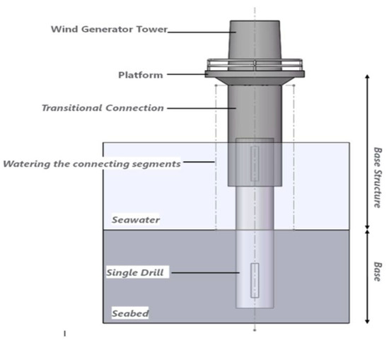
Figure 1.
Wind farm grouted joint.
The tubular joints are the most critical parts of a tubular structure. A tubular joint reinforced with a collar plate is used to improve the strength of the connecting segment [4]. It is concluded that the collar-plate reinforcement method is a valuable alternative for tubular connection design [5].
The study of grouted connections without shear bonds can be traced back to the 1960s. Evans concluded that the shearing strength and bonding force of the joint section were mainly related to the characteristics of the grouting material and the roughness of the steel pipe surface [6]. Later, experimental research on the bond strength of the joint segment became more systematic, and the parameters relative to the joint segment became more comprehensive. Billington’s experimental study found that the ultimate bond strength of the grouted joint section was proportional to the radial stiffness coefficient of the grouted joint section and the compressive strength of the grouting material and obtained the calculation formula of the ultimate bond strength [7]. Through the grouted connecting section test and actual engineering application, it was found that a grouted connecting section without shear bonds had low axial stress performance and was prone to vertical slip. Therefore, some scholars began to focus on the influence of shear bonds on the axial bearing capacity of the grouted connecting section. In 1988, Forsyth, Tebbett, et al. studied the influence of setting shear bonds on the ultimate bond strength of grouted joints. They observed that when the height-to-distance ratio of the shear bonds was less than 0.075, the bond strength had a linear relationship with the height-to-distance ratio [8]. In 2009, Huang Liwei and Yang Feng established a scaled model of the grouted connecting section of the catheter and conducted static tests. The test results showed that the connection performance of the grouted connecting section with shear bonds was much higher than that without shear bonds [9,10]. In 2014, Li Wei et al. conducted axial static load tests on the grouted connecting section of a large-diameter, single-pile foundation [11]. The test results indicated that the axial bearing capacity of the grouted connection without shear bond depended on the bond strength between grout and steel pipe, and the axial bearing capacity and deformation performance of the connecting section was significantly improved after setting the shear bond. Therefore, the comprehensive performance of a grouted joint can be improved significantly with the addition of shear bonds.
Most of the above experimental studies used scale models, which have certain size effects, scale errors, and necessary simplifying assumptions. Instead, numerical simulations can define the complex boundary conditions and contact relations of joint segments, and the output parameters, such as stress, deformation, and damage, are more precise. In 2012, Zhong Weiqiu et al. conducted FE simulations of the grouted connecting segment. They found that the axial load of the connecting segment without shear bonds was mainly borne by the bonding force of the contacting surface and the mechanical biting force, and the setting of shear bonds could significantly improve the axial bearing capacity of the grouted connecting segment [12]. In 2012, M Klose simulated the axial bearing capacity of the grouted connecting section with shear keys. The results show that the axial load is transmitted by the shear action between the shear keys and the grouting material, and the stress concentration occurs within the grout close to the shear bond. The grouted joints with shear key can still continue to bear the load after reaching the axial bearing capacity, The failure process shows certain plastic characteristics [13]. Some other scholars simulated the axial bearing capacity of grouted joints [14]. The results indicated that the shape, size and angle of shear keys have great influences on the stresses of grout.
In summary, the experimental studies of grouted joints of the pile foundations are limited to the study of scaler models. Numerical simulations are more suitable for the mechanical analysis of the full-size structure instead of experimental methodology. Performing the numerical simulations, the stress state can be more accurately described by using plastic damage model than that of non-damage elastic one. Therefore, a full-size plastic damage model of the grouted joints is established in this paper based on the Sidiroff energy equivalence principle, and the stresses, deformations of steel pipe and grout in the connecting section are analyzed, where shear bonds with different shapes and different quantities were designed.
2. Fundamental Principle
2.1. Axial Bearing Capacity of Grouted Joints
The grouted joints of single-pile foundation with shear bond are shown in Figure 2.
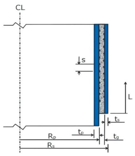
Figure 2.
Diagram of grouted connecting section of single pile foundation with shear bond.
The circumferential shear bonds are set on the aspectant surfaces of the upper and lower steel pipes. Under axial load, cracking of the grouting material could be avoided effectively. Once the crack occurs in the joints, stress will be redistributed, and the load could be transmitted normally. It is assumed that the axial load is evenly distributed on all the shear bonds.
The load over the unit length of the annular shear bond is:
In Equation (1), Rp is the outer radius of the steel pile; Pa,d is the axial load acting on the joint segment; n is the number of effective shear bonds on both sides of the grouted connecting section.
The interface shear strength of the grouted joints with shear bonds is:
In Equation (2), h is the height of the shear bonds measured radially from the surface of steel pipe; Dp is the diameter of steel pipe; fbk is the cubic compressive strength of the grouting material; s is the vertical distance between adjacent shear keys; k is the radial stiffness coefficient, which is defined as:
In Equation (3), Eg is Young’s modulus of grouting material; Rs is the outer diameter of the upper pipe; ts is the wall thickness of the upper pipe. The interface shear strength fbk shall not be greater than the compressive strength of the grouting material.
The axial bearing capacity of the grouted joints with shear bonds is mainly related to the compressive strength of the grouting material, the parameters of shear keys and the size of the connected section.
2.2. Flexural Capacity of Grouted Joints
For the grouted joints of single-pile foundation, shear bonds are mostly fixed in the middle 1/2 area of the grouted connection, as shown in Figure 3. In this area, the grouting material and steel pipe should not be separated obviously when subjected to bending moment.
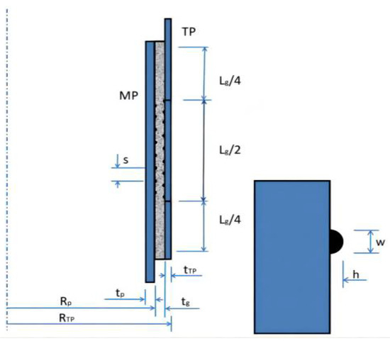
Figure 3.
Geometric dimensions of grouted joint of single-pile foundation.
When subjected to bending moment, the maximum nominal radial pressure pnom at the top and the bottom parts of the grouted joint is calculated as follows:
In the Equation, keff is the effective spring stiffness of the shear bond; μ is the characteristic friction coefficient, which can be assigned as 0.7; Rp is the outer radius of steel pipe pile; Rtp is the outer radius of upper pipe; tp is the wall thickness of the steel pile; ttp is the wall thickness of the upper pipe; Lg is the effective length of grouted section; L is the full length of the grouted section; tg is the thickness of the grouting material.
The effective spring stiffness per unit length of the grouted connecting segment with n shear keys is expressed as:
In Equation (5), seff and s are the effective vertical spacing and vertical center spacing, respectively, between two adjacent shear keys; ω is the width of shear key; E is the elastic modulus of steel; μ is the Poisson’s ratio of steel; n is the number of effective shear bonds (the actual number of shear bonds on both sides of the grouted joint is n + 1); φ is the design coefficient (it is assigned as 1.0 in the calculation of the load on the shear bond, and 0.5 in the calculation of the maximum nominal radial contact pressure).
The maximum nominal contact pressure generated by the bending moment should meet the following requirement:
The flexural capacity of the grouted joints could be limited by controlling the maximum nominal contact pressure between the steel pipe and the grouting material at the end of the grouted section. Under bending moment, the steel pipe and the grouting material at the end of the grouted joints squeeze each other. The limitation of the maximum nominal contact stress between the steel pipe and the grouting material ensures that the crushing of the grouting material and the yielding of the steel pipe could be avoided.
2.3. Material Theory and Model Validation
The grouted connection involves steel and grouting material. Based on the classical metal plasticity theory, the elastoplastic material model is adopted for the steel, which meets the Von Mises yield criterion, and the constitutive relationship conforms to the bilinear kinematic hardening model. For the high strength grouting material, a plastic damage model is selected to simulate its mechanical behaviors [15]. In the application of plastic damage model, damage factor is to be defined, whose calculation methods include energy equivalence principle method, graphic method, Najar method, Mander method, maximum fatigue strain method, etc. [16]. In this paper, Sidiroff energy equivalence principle is used to calculate the damage factor.
The Sidiroff’s energy equivalence principle assumes that a stress acting on the damaged material and the non-damaged material produce the same residual energy [17]. When the plastic damage model is used to simulate the compression and tension behavior of grouting materials, a series of parameters need to be determined [18]. By referring to the parameter of high-strength concrete and the test results of scholars such as Chen Guochen [19], Wu Yuan [20] and Zhang Yi [21], the parameters are determined as follows: (i) The expansion angle (φ) at high confining pressure in p-q plane is set as 38 degrees; (ii) The rheological angle (ε) of the plastic potential energy equation is 0.1; (iii) The ratio of concrete strength under biaxial compression to uniaxial compressive strength is 1.16; (iv) The ratio of the second stress invariant (Kc) on the pull meridian q(TM) to that on compression meridian q(CM) is 2/3; (v) The default value of viscosity coefficient is 0.0001; (vi) The tensile and compressive stress-strain curves of high-strength grouting materials are calculated by the Yu Zhiwu-Ding Faxing constitutive equation [22]. (vii) Damage factors are calculated by the energy equivalence principle.
The uniaxial compression stress-strain curve of grouting material obtained by simulation, as well as the result derived by constitutive formula are shown in Figure 4.
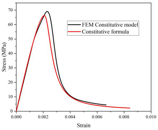
Figure 4.
Comparison of stress-strain curves of high strength grouting material under compression.
The two curves are highly coincident. They have obvious elastic and elastic-plastic stages. The ultimate load of grouting material obtained by numerical simulation is 1551 kN, while that calculated by constitutive formula is 1495 kN. It shows that the constitutive model of material used in this paper is feasible.
2.4. Modeling Theory and Experimental Confirmation
The meshing technique is critical in modeling the grouted joints. To analyze the mechanical behaviors under axial load, axisymmetric models are established by using Hex mesh, where four-node quadrilateral bilinear uncoordinated axisymmetric unit (CAX4I) is adopted. Under bending moment action, the three-dimensional solid models are established, and the eight-node hexahedral linear reduction integral unit (C3D8R) is used for the whole grouted joints. It is assumed that the steel pipe firmly contacts with the grout surface in the normal direction, where the interface pressure can be completely transmitted between the interfaces. When the contact pressure is zero or negative, the contact surface between the steel pipe and the grouting material will be separated. The contact in the tangential direction satisfies the Coulomb friction model, where the shear stress can be transferred on the interface. Before the shear stress reaches the critical value, there is no relative displacement on the contact surface between the steel pipe and the grouting material. A reference point is set at the position of the upper end of the steel pipe in the connecting section model, which is coupled with the upper end of the steel pipe in the grouted connecting section, and the load acts on the reference point [2,15,23,24].
In order to verify the effectiveness of the numerical simulation method for grouted joints, an FE model is established referencing Lee’s experiment [22]. The size, material properties and loading mode are all corresponding to the grouted joints in the test. The numerical simulations are highly consistent with the experimental results, as shown in Figure 5 and Figure 6. The overall trend of the curves is generally consistent. The peak load of the FE model is 5623 kN, and that of the test is 5394 kN. The error is 4.2%, which is within the acceptable range. It shows that the modeling and numerical simulation method are reliable.
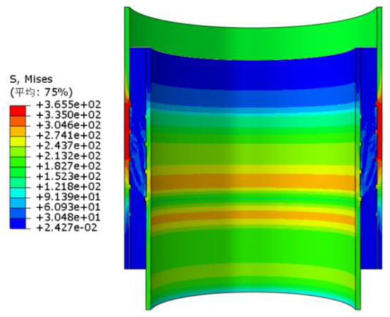
Figure 5.
Mises stress of the grouted joint.
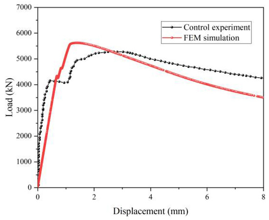
Figure 6.
Comparison of simulation and experiment.
The simulated failure mode of the grouting material is compared with the experimental one. The tensile damage cloud diagram and the image of experiment are shown in Figure 7.
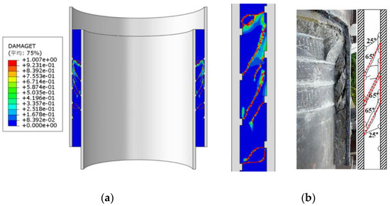
Figure 7.
Comparison of the cloud diagram of grout’s tensile damage with the experimental damage. (a) Cloud diagram of tensile damage. (b) Comparison of fracture morphology.
In Figure 7, the simulated fracture morphology, position and cracking angles are coincident with that of the test. The load-displacement curve and failure pattern of the model are in good agreement with Lee’s test results. The FE model can actually simulate the mechanical characteristics of the grouted connection.
The resistance against fatigue is generally quantified in terms of the number of cycles or time (days/years) prior to failure, because of which it is usually named fatigue life [25]. This study can be further extended to improve the current research results and establish a more advanced model to capture the fatigue behavior of concrete and the interface [26]. The optimization of shear keys in the grouted joints is considered to improve the distribution of stress and deformation, improve the durability, and extend the service life of the offshore wind power plant [27,28,29].
3. Result and Discussion
3.1. Influence of Shear Key Shape on the Bearing Capacity
To investigate the influence of shear keys on the bearing capacity of grouted joints, shear keys with three shapes are employed. It is shown in Figure 8.
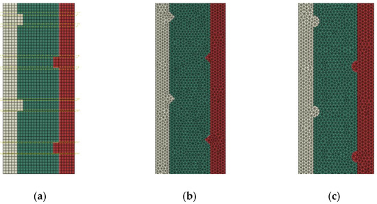
Figure 8.
Shear keys of three shapes. (a) Rectangle. (b) Triangle. (c) Semicircle.
Under a specified axial load, shear keys with different shapes lead to different stresses in the grout. So, the Tresca stress is applied to judge whether a shear key of a certain shape is appropriate or not. According to the numerical simulation results, the Tresca stresses of the grout close to the internal and external steel walls are extracted, and the axial distribution of the Tresca stress is shown in Figure 9.
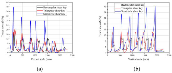
Figure 9.
Tresca stresses axial distribution in grout along the internal and and external steel walls. (a) Stresses close to internal wall. (b) Stresses close to external wall.
The maximum Tresca stresses are 27.09 MPa, 20.05 MPa and 40.38 MPa for the rectangle, triangle and semicircle keys, respectively. The position of peak Tresca stress values for the three shapes are all close to the first shear key. The distribution of peak stresses at the shear keys along the internal and external walls is opposite. There is plastic damage in the grout at the shear keys, and local failure occurs at the end shear keys. The phenomenon of stress concentration corresponding to the semicircular shear key is more serious. Therefore, the force transmission efficiency of the grouted connection by using the rectangular and the triangular shear keys is more reasonable than that of the semicircle.
Under specific bending moment, the maximum principal stress criterion is used to judge whether the grouting material is damaged under tension and compression. A higher principal stress is more likely to lead to damage of the grout. The maximum principal stresses in the grout close to the shear keys are as follows in Table 1.

Table 1.
The maximum principal stresses in the grout.
Under the bending moment, the maximum compressive stress of the semicircular shear key is still the largest, but the principal tensile stress is the smallest. Although the triangle shear keys lead to the lowest principal compressive stress, the tensile stress is much higher. It means that the grouted joints of triangular shear keys are more prone to be destructed by tension under bending moment. However, bending moments can lead to failure of the grouted joints of semicircular shear keys because of compression. The stresses and displacement in the grouted joints of rectangular shear keys under bending moment load are a bit smaller than those of the triangular shear keys, and the steel pipe is more closely connected with the grouting material.
3.2. Influence of Shear Key Size on Bearing Capacity
3.2.1. Being Subjected to Axial Compression
In order to investigate the influence of shear key size on the bearing capacity, shear keys with different sizes are adopted to simulate the maximum Mises stresses in the steel pipes, maximum Tresca stresses in the grout and maximum vertical displacements of grouted joints.
The variation of maximum stress/displacement of steel pipes and grout with rectangular shear keys in different heights is shown in Figure 10.
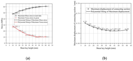
Figure 10.
Variation trend of maximum stress/displacement of joints with shear key in different heights. (a) Maximum stress. (b) Maximum vertical displacement.
In Figure 9, the maximum Mises stress in the steel pipe increases with the height of the shear key, and the maximum Tresca stress in grout decreases because of the increasement of the contact area between the shear key and the grout. A higher shear key lead to higher stress, especially at the end shear key of the connecting segment. Therefore, the shear key’s height is proposed to be limited within 35 mm.
The maximum vertical displacement of the connecting segment goes down gradually with the increasing height of the keys. The mechanical binding force between steel pipe and grouting material is strengthened.
The influence of a varied width of the shear keys on the axial mechanical performance of the grouted joints is analyzed. The maximum Mises stresss in the steel pipe, maximum Tresca stress in the grout and vertical displacement are shown in Figure 11.
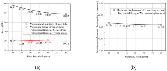
Figure 11.
Variation of maximum stresses and displacement of grouted joints with shear keys in different widths. (a) Stresses in steel and grout. (b) Vertical displacement.
The uper and lower compressive area of the shear keys is unchanged. So, the maximum Tresca stress in the grout changes slightly under the same axial load. The increased shear key width results in the relief of the stress concentration at the shear bond position, so as to the maximum Mises stress in the steel pipe. The maximum vertical displacement in the connecting section basically remains constant, for which the change in width has little effect on the force transmission between steel pipe and grout.
3.2.2. Being Subjected to Bending Moment
Under bending moment, The variation trends of maximum stresses in steel pipes and grout, as well as the maximum displacement of the grouted joints are shown in Figure 12.
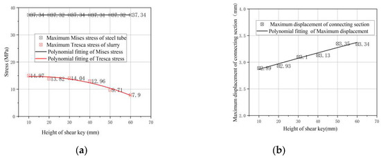
Figure 12.
Variation trend of maximum stress/displacement of grouted joints with shear keys in different heights. (a) variation of stresses. (b) The change of displacement.
In Figure 12. Variation of shear key’s height has little impact on the maximum Mises stress of the steel pipe. The maximum Tresca stress in the grout decreases by 47 percents with the shear key’s height raising from 10 mm to 60 mm, and the stress concentration is relieved significantly. The maximum horizontal displacement of the joint segment increases by 15.6% with the increase of shear bond height, which is caused by the decrease of grout thickness in the grouting area. Through the interaction between shear keys and grouting material, the bending moment transmission is no longer only dependent on the end of the grouted joint, but the middle grouting area is also involved, so that the bending moment can be transferred from the inner pipe to the outer pipe more smoothly.
The Mises stresses vertically along the steel pipe with shear keys’ heights of 10 mm, 30 mm and 60 mm are extracted, as shown in Figure 13.
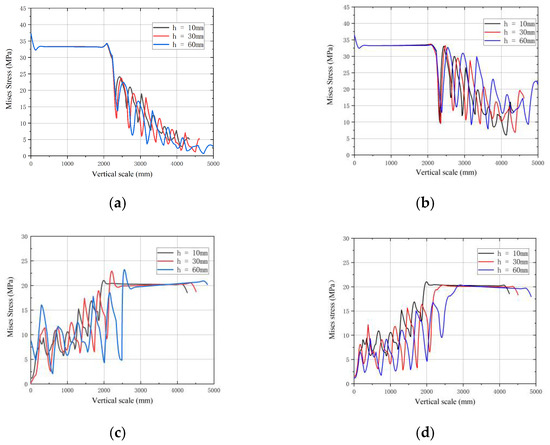
Figure 13.
Mises stresses along the inner and outer steel pipe . (a) Compression side of the inner pipe. (b) Tension side of the inner pipe. (c) Compression side of the outer pipe. (d) Tension side of the outer pipe.
It indicates in Figure 13a,b that Mises stress on the tension side of the inner pipe is greater than that on the compression side, especially the stress at the shear keys. Stress concentration is obvious at the position of the shear bond. The Mises stress in the inner pipe is gradually reduced from the first shear key at the upper end to the lower end of the joint. It shows at the Figure 13c,d that the regularities of stress distribution in the outer pipe are opposite to that of the inner pipe. The Mises stress of the outer pipe is mainly concentrated in the shear bond position of the lower part, which gradually increases from the first shear bond at the uper position to the last one at the bottom. As the height of shear keys increased from 10 mm to 60 mm, Mises stress and its distribution did not change significantly at both sides of the pipes.
The vertical distribution of the Tresca stresses in grout at the compression side along the inner and outer steel walls are shown in Figure 14.
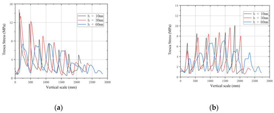
Figure 14.
Distribution of Tresca stresses in grout along steel walls. (a) Stresses along the inner wall. (b) Stresses along the outer wall.
At the compression side, the peak Tresca stress in the grout along the inner wall is greater than that along the outer wall. The stresses in both steel walls are concentrated at the shear bonds. A higher shear key leads to a lower Tresca stress. The highest stress along the inner wall is at the first shear bond at the top, and the peak value declines in turn. The Tresca stress distribution along the outer wall is different, where the highest stress is close to the middle position of the connection. As the shear bond height increased from 10 mm to 60 mm, the Tresca stress in the grout turns lower, which means that the stress concentration in the grout is alleviated.
Considering the influence of shear key width on the bending bearing capacity, different widths are adopted. The variation of maximum stress and maximum horizontal displacement of the grouted joints under bending moment is shown in Figure 15.
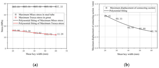
Figure 15.
Variation trend of maximum stress/displacement of grouted joints with different shear bond widths. (a) Stress. (b) Displacement.
In Figure 15, the maximum Tresca stress in grout decreased by 23.7% as the shear key width increases from 20 mm to 60 mm, and the maximum horizontal displacement of grouted joints decreased by 20%. Therefore, appropriately increasing the shear bond width can reduce the maximum stress and horizontal displacement of grouted joints.
4. Conclusions
In this paper, the FE models of the grouted joints of offshore wind turbine tower is established based on plastic damage theory. The reliability of the simulation method is verified by comparing the simulation results with the test results in the aspects of load-displacement curve, ultimate bearing capacity and failure process. The relationships between the mechanical performance of the grouted joints and the shear keys with different shapes and sizes are analyzed. Under axial load, the stresses concentrate at the shear bond position, and the stress concentration at the end is more obvious. The Tresca stresses generated by the semicircular shear keys in the grout are significantly greater than that of rectangle and triangle, which means that the semicircular shear keys are detrimental for the grouted joints in bearing axial load. Under the bending moment, the maximum compression stress of the semicircular shear key is still the largest, but the principal tensile stress is the smallest. The triangle shear keys lead to the highest tensile stress, which means that the grouted joints of triangular shear keys are more prone to be destructed by tension under bending moment. The maximum tensile and compressive stresses generated by the rectangular shear keys are in the medium. The comprehensive performance of rectangular shear bond is better in load transmission and resistance to deformation than those of triangle and semicircle.
For the grouted joints with rectangular shear keys, the maximum stress in the grout and the maximum vertical displacement under axial load tend to be reduced by moderately increasing the shear bond height, but the variation of shear bond width has little effect on the vertical displacement and the axial mechanical performance of the grouted joints. Under a bending moment, a higher shear keys lead to obvious reduction of the maximum stresses in the grout, and the maximum horizontal displacement of the connecting section increases slightly.
For the grouted connection of single-pile foundation of the 4 MW offshore wind turbine, it is recommended that the rectangular shear keys are staggered on inner and outer steel pipes, and the spacing could be 300 mm. As to the size, heights of 30–40 mm and widths of 50–60 mm are appropriate.
Author Contributions
Conceptualization, Y.C. and X.M.; Formal analysis, Y.C. and W.S.; Funding acquisition, X.M.; Investigation, L.Z. and C.H.; Methodology, L.Z. and C.H.; Resources, W.S.; Software, L.Z.; Writing—original draft, L.Z. and Y.C.; Writing—review & editing, W.S. and X.M. All authors have read and agreed to the published version of the manuscript.
Funding
This research received no external funding.
Institutional Review Board Statement
Not applicable.
Informed Consent Statement
Not applicable.
Data Availability Statement
The data presented in this study are available on request from the corresponding author.
Conflicts of Interest
The authors declare no conflict of interest.
References
- Li, X.; Abeynayake, G.; Yao, L.; Liang, J.; Cheng, F. Development status and prospects of offshore wind power in Europe. Glob. Energy Internet 2019, 2, 116–126. [Google Scholar]
- He, R.; Zhu, T. Model Tests on the Frequency Responses of Offshore Monopiles. J. Mar. Sci. Eng. 2019, 7, 430. [Google Scholar] [CrossRef]
- Sunday, K.; Brennan, F. A review of offshore wind monopiles structural design achievements and challenges. Ocean. Eng. 2021, 235, 109409. [Google Scholar] [CrossRef]
- Nassiraei, H. Static strength of tubular T/Y-joints reinforced with collar plates at fire induced elevated temperature. Mar. Struct. 2019, 67, 102635. [Google Scholar] [CrossRef]
- Nassiraei, H. Geometrical effects on the LJF of tubular T/Y-joints with doubler plate in offshore wind turbines. Ships Offshore Struct. 2022, 17, 481–491. [Google Scholar] [CrossRef]
- Evans, G.W.; Carter, L.G. Bounding Studies of Cementing Compositions to Pipe and Formations; API Division of Production: Duncan, OK, USA, 1962; pp. 72–79. [Google Scholar]
- Billington, C.J.; Lewis, G.H. The strength of large diameter grouted connections. In Proceedings of the Tenth Annual Offshore Technology Conference, Houston, TX, USA, 8–11 May 1978; pp. 291–301. [Google Scholar]
- Forsyth, P.; Tebbett, I.E. New test data on the strength of grouted connections with closely spaced weld beads. In Proceedings of the Offshore Technology Conference, Huston, TX, USA, 2–5 May 1988; pp. 237–245. [Google Scholar]
- Aritenang, W.; Elnashai, A.S.; Dowling, P.J.; Carroll, B.C. Failure mechanisms of weld-beaded grouted pile/sleeve connections. Mar. Struct. 1990, 3, 391–417. [Google Scholar] [CrossRef]
- Huang, L.; Yang, F.; Zhang, J. Grouting connection between offshore fan pile foundation and jacket. Water Conserv. Hydropower Technol. 2009, 40, 39–42, 45. [Google Scholar]
- Li, W.; Bian, E.; Zhong, W.; Fang, T.; Jiang, P.; Xu, J. Axial static load test of grouting connection section of large diameter single pile foundation for offshore wind power. J. Water Conserv. Waterw. Eng. 2014, 41–46. [Google Scholar]
- Zhong, W.; Ma, Y.; Yang, L.; Li, W. ANSYS analysis of the connection between offshore wind turbine pile foundation and jacket grouting. J. Shenyang Jianzhu Univ. Nat. Sci. 2012, 28, 663–669. [Google Scholar]
- Klose, M.; Mittelstaedt, M.; Mulve, A. Grouted Connections—Offshore Standards Driven by the Wind Industry. In Proceedings of the 22nd International Offshore and Polar Engineering Conference, Rhodes, Greece, 17–22 June 2012. [Google Scholar]
- Tao, C.; Cheng, C.; Cao, C.; Zhang, X.; Wang, K.; Guo, K. Numerical modeling and parametric analysis of grouted connections under axial loading. Thin-Walled Struct. 2020, 154, 106880. [Google Scholar]
- Vieira, M.; Viana, M.; Henriques, E.; Reis, L. Soil Interaction and Grout Behavior for the NREL Reference Monopile Offshore Wind Turbine. J. Mar. Sci. Eng. 2020, 8, 298. [Google Scholar] [CrossRef]
- Sun, W.; Xia, S. Study on the method for evaluating damage factors of shear bond concrete in open plate based on damage plastic model. Sichuan Build. Sci. 2017, 37, 142–146. [Google Scholar]
- Guo, J.; Xu, B. Study on the value and application of damage factor of concrete damage plastic model. J. Gansu Sci. 2019, 31, 88–92. [Google Scholar]
- Whang, J.; Chen, Y. Application of ABAQUS in Civil Engineering; Zhejiang University Press: Hangzhou, China, 2006. [Google Scholar]
- Chen, G. Mechanical properties and reliability analysis of high strength grouting material for offshore fan. Ship Eng. 2020, 42, 600–604. [Google Scholar]
- Wu, Y.; Yang, X.; Wang, K.; He, T. Study on uniaxial compressive stress-strain curve test of grouting material. Ind. Build. 2014, 44, 909–913. [Google Scholar]
- Zhang, Y. Study on Fatigue Bearing Capacity of Offshore Fan Grouting Connection. Ph.D. Thesis, Zhejiang University, Hangzhou, China, 2018. [Google Scholar]
- Yu, Z.; Ding, F. Unified calculation method for mechanical properties of concrete under compression. J. Build. Struct. 2003, 41–46. [Google Scholar]
- Lee, J.H.; Won, D.H.; Jeong, Y.J.; Kim, S.H.; Kang, Y.J. Interfacial shear behavior of a high-strength pile to sleeve grouted connection. Eng. Struct. 2017, 151, 704–772. [Google Scholar] [CrossRef]
- Sánchez, S.; López-Gutiérrez, J.-S.; Negro, V.; Esteban, M.D. Foundations in Offshore Wind Farms: Evolution, Characteristics and Range of Use. Analysis of Main Dimensional Parameters in Monopile Foundations. J. Mar. Sci. Eng. 2019, 7, 441. [Google Scholar] [CrossRef]
- Carrara, P.; de Lorenzis, L. A coupled damage-plasticity model for the cyclic behavior of shear-loaded interfaces. J. Mech. Phys. Solids 2015, 85, 33–53. [Google Scholar] [CrossRef]
- Duru, K.; Gabriel, A.A.; Kreiss, G. On energy stable discontinuous Galerkin spectral element approximations of the perfectly matched layer for the wave equation. Comput. Methods Appl. Mech. Eng. 2019, 350, 898–937, Corrigendum in Comput. Methods Appl. Mech. Eng. 2022, 398, 115050. [Google Scholar] [CrossRef]
- Kirane, K.; Bažant, Z.P. Microplane damage model for fatigue of quasibrittle materials: Sub-critical crack growth, lifetime and residual strength. Int. J. Fatigue 2015, 70, 93–105. [Google Scholar] [CrossRef]
- Wang, Y. Physical stochastic damage model for concrete subjected to fatigue loading. Int. J. Fatigue 2019, 121, 191–196. [Google Scholar] [CrossRef]
- Baktheer, A.; Aguilar, M.; Chudoba, R. Microplane fatigue model MS1 for plain concrete under compression with damage evolution driven by cumulative inelastic shear strain. Int. J. Plast. 2021, 143, 102950. [Google Scholar] [CrossRef]


Publisher’s Note: MDPI stays neutral with regard to jurisdictional claims in published maps and institutional affiliations. |
© 2022 by the authors. Licensee MDPI, Basel, Switzerland. This article is an open access article distributed under the terms and conditions of the Creative Commons Attribution (CC BY) license (https://creativecommons.org/licenses/by/4.0/).