Article

Dynamic Analysis of an Autonomous Underwater Glider with Single- and Two-Stage Vibration Isolators

1
School of Marine Science and Technology, Northwestern Polytechnical University, Xi’an 710072, China
2
Key Laboratory of Unmanned Underwater Vehicle, Northwestern Polytechnical University, Xi’an 710072, China
*
Author to whom correspondence should be addressed.
J. Mar. Sci. Eng. 2022, 10(2), 162; https://doi.org/10.3390/jmse10020162
Submission received: 4 January 2022 / Revised: 24 January 2022 / Accepted: 25 January 2022 / Published: 26 January 2022
(This article belongs to the Section Ocean Engineering)

Abstract

:
Vibrations from the power system can significantly affect the working performances (ocean observation) of autonomous underwater gliders (AUGs). In order to reduce the vibration transmission from vibration sources to the precision instruments in AUGs, single- and two-stage vibration isolator rings are designed in this paper. The dynamic models of the single- and two-stage vibration isolation of the AUG are presented. The force transmission ratio of the AUG is calculated in MATLAB code. The influences of the isolator and the structure stiffness are analyzed. The dynamic stiffness of the designed isolators, as an important design parameter, is calculated using the finite element method. The influence of the designed parameter on the dynamic stiffness of the rubber ring isolator is discussed. The coupled vibro-acoustic finite element method is used to analyze the vibration and acoustic response of an AUG with the single- and two-stage vibration isolators. The insertion loss is calculated in order to assess the vibration isolation performance of the single- and two-stage vibration isolators. The results from the dynamic models and the finite element models both show that the vibration isolation performance of the two-stage vibration isolator ring performs better than that of the single-stage vibration isolator ring.

1. Introduction

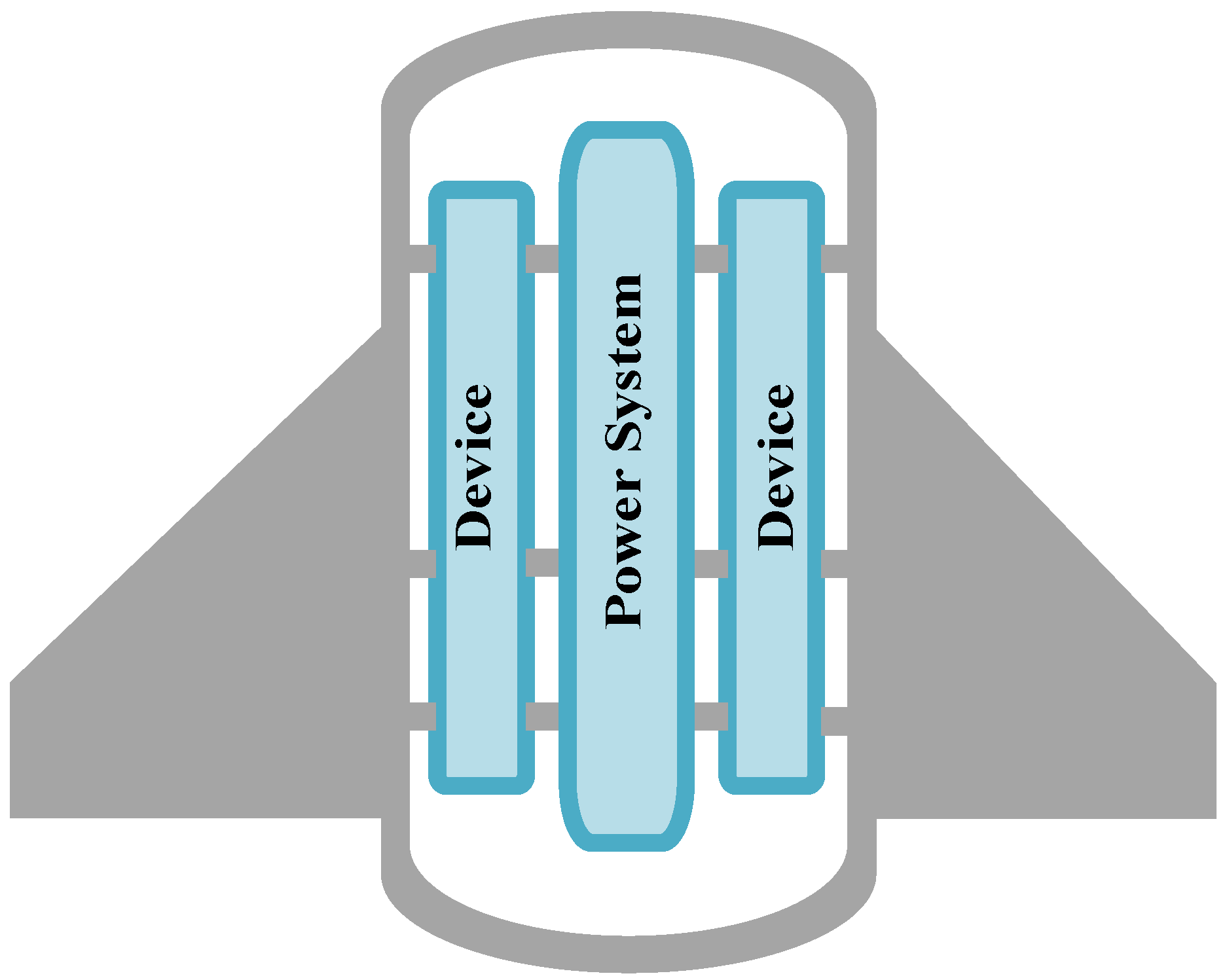
As a new type of underwater vehicle [1,2,3,4,5,6,7], autonomous underwater gliders (AUGs)—driven by a centroid-adjusting mechanism and buoyancy-adjusting mechanism, and not an external propulsion system—have the advantages of a low energy consumption, low cost and great endurance. By the exploration of the commercial potential, the AUGs have been developed into various types in application. The AUGs have irreplaceable advantages in coastal and open-ocean observation [8], in fine horizontal scales and long time periods. The AUGs can be propelled by changing the buoyancy and centroid. The power system works briefly in the periodic cycle, as shown in Figure 1. Therefore, the energy cost of the AUGs is minuscule. As the travel speed of the AUGs is less than 0.5m/s, minute hydrodynamic flow noise is caused [9]. The main vibration and acoustics of the AUGs come from the internal mechanical vibrations, as the motions of the gears [10,11,12], shaft, and bearings generate large vibrations and acoustics [13,14]. Figure 2 displays the internal structure layout of the AUG. The power systems and battery are modularly installed in the body of the AUG. The electrical precision instruments are placed in the wing. Song et al. [15] studied the influence of the buoyancy-adjusting mechanism on the turbulence observation by using an experiment. The results showed the gear-meshing frequency from the oil pump in the buoyancy-adjusting mechanism would massively affect the turbulence observation. Wang et al. [16] discussed the feasibility of the application of vector hydrophones to underwater gliders by conducting a self-noise test. The experimental results showed the signals received by the vector hydrophones is interfered with by the self-noise produced by the mechanical devices.
As the mechanical systems are modularly installed inside the AUG, the vibration isolation technology [17,18] could effectively reduce the dynamic coupling of different mechanical parts. Ravindra and Mallik [19] modelled the non-linear vibration isolation system under the force excitation and base excitation. They analyzed the effect of the damping on the system transmissibility. Yilmaz and Kikuchi [20] theoretically analyzed the n − 1 single-degree-of-freedom dynamic vibration absorbers and n lever-type anti-resonant vibration isolators in series by considering the stiffness and mass limitation. Kari [21] solved the dynamic stiffness of preloaded vibration isolators by using a nonlinear finite element procedure. The modelling results agreed with the experimental results. The advanced global optimization methods [22] are available to search for the optimal design parameters. Jazar et al. [23] utilized the root mean square of the absolute acceleration and the relative displacement as the cost function in order to find the optimal value for a linear single-degree-of-freedom vibration isolator mount. Majak et al. [24] applied the genetic algorithm to determine the optimal values of the impact parameters based on an energy absorbing structure design optimization problem.
Vibration isolators are widely employed in the vibration reduction of underwater vehicles. Song et al. [25] proposed a periodically layered isolator for the reduction of the vibration from the propeller force in the underwater vehicle. Yang et al. [26] designed three different vibration isolator rings for the power system of the underwater vehicle, and evaluated their isolation effects based on insertion loss and the vibration energy level drop. Liu et al. [27] presented a chaos anti-control technology in a nonlinear vibration isolation system used for the controlling of the line-spectra water-born noise of the underwater vehicle. Liu et al. [28] proposed dynamic models of the propeller-shaft-hull system with diverse vibration isolators, and investigated the force transmission ratio in these models. The vibration isolator has many types of structural design form in engineering applications [29,30]. The rubber ring isolator is generally utilized in the power system due to the superiority of its large damping, light weight and small space characteristics. Zhang and Richards [31] developed the identified Maxwell models with two Maxwell elements for the accurate measurement of the dynamic characteristics of a rubber isolation system. Gil-Negrete et al. [32] used a commercial FE code to predict the dynamic stiffness of filled rubber isolators. Jin et al. [33] proposed a dynamic stiffness calculation method for the rubber ring isolator for the engine, and produced the law of dynamic stiffness. When the power system is connected to the rubber ring isolator, the isolation system is viewed as a single-stage vibration isolation system. A two-stage vibration system [34,35,36,37] with intermediate mass inserted in the mass-spring-foundation system attenuates more vibration energy than single-stage vibration isolation. Scholars have paid plentiful attention to the structural implementation and dynamic modelling of the two-stage vibration isolation for the engineering applications. Moore [34] adopted a matrix methodology to derive the dynamic model equation of the generalized two-stage vibration isolation system. Li et al. [35] studied the dynamic characteristic of a roller test-bed based on theoretical analysis and the rigid–flexible coupling simulation method. However, the structure design and vibration characteristics of the two-stage rubber ring vibration isolator for the power system of the AUG were seldom investigated in the listed references.
In classic vibration isolation dynamic modeling, the analysis assumed that the isolator is mounted on the rigid foundation. Scholars noticed that the coupling of the foundation stiffness and the vibration isolation system mounted on the beam, plane, and cylinder can affect the system vibrations’ performance [38,39,40]. Pan [38] adopted the power flow method to evaluate the vibration transmission from a rigid body to an elastic thin plane. Xie et al. [39] developed a rigid–elastic coupled dynamic model consisting of a rigid vibrating machine, multiple resilient mounts and a floating elastic panel in order to analyse the vibration transmission characteristic. The above research revealed that the elasticity of the vibration isolation system’s foundation can affect the vibration transmission. The elasticity of the foundation is strongly related to the impedance or the dynamic stiffness of the foundation.
When the AUG is submerged underwater, the dynamic vibration of the AUG is coupled with the hydrodynamics. The influence of the hydrodynamics could be defined as the equivalent mass of water added to the structure on the AUG, which is called the apparent mass. Puri et al. [41] derived a reduced-order model for low-frequency, undamped, fully coupled structural-acoustic analysis. Junge et al. [42] presented an FE–BE coupled method to solve the vibro-acoustic problem of the underwater structure. Peters et al. [43,44] investigated the effect of the apparent mass on the radiated sound characteristic of an underwater vehicle under the excitation of propeller. They found that the apparent mass could cause the increase of the radiated sound.
In this paper, single- and two-stage rubber ring isolator structures suitable for the power system of the AUG are first proposed. Then, the dynamic models of the single- and two-stage vibration isolation of the AUG are respectively derived, considering the structure stiffness. The force transmission ratios of the proposed dynamic models are analyzed theoretically, and the influence of the isolator and structure stiffness on the vibration characteristic are investigated. Finally, the finite element method is used to analyze the dynamic stiffness of the rubber ring isolator, and to solve the vibration response, the acoustic response and the insertion loss of the AUG with the single- and two-stage vibration isolators.

2. Structure Design of the Single- and Two-Stage Vibration Isolation Systems

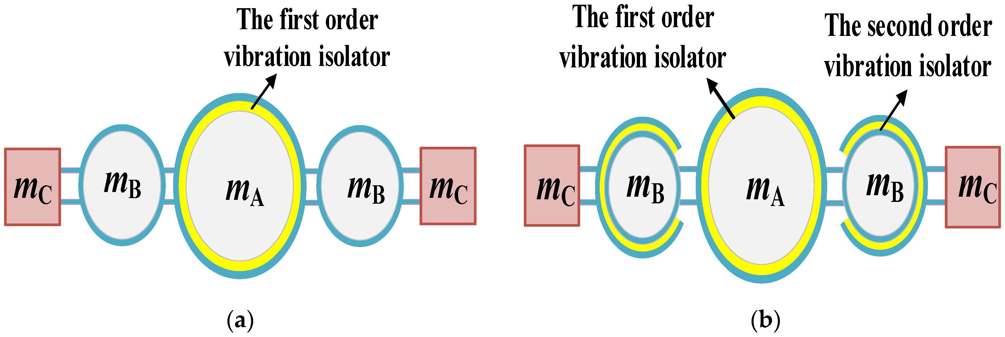
In the AUG, the vibration energy is contributed from the power system and transmitted to the battery and the wing. The power system and the battery are modularly designed, and are supported by the metal frame that is connected to the wing. The precision instruments are installed on the wing for ocean research. The vibration isolation system is designed to avoid the vibration energy affecting the work of the electrical instrument. In engineering applications, the vibration isolators have been used extensively to effectively reduce the vibration energy transmission to the protected part, in which the rubber ring isolator is a common choice for the power system. Therefore, the rubber ring isolator is selected as the vibration isolation element of the energy isolation, rather than the single-stage vibration isolation; the former has been widely used in the vibration control design in the fields of ships, airplanes and vehicles. However, there is little research about the design of a two-stage vibration isolation structure for the AUG; the related analysis is much less. A new two-stage vibration isolator for the AUG is proposed, as given in Figure 3. Figure 3a presents the single-stage vibration isolation system. Figure 3b shows the two-stage vibration isolation system. In Figure 3, the first-order vibration isolator is the rubber ring attached to the power system; the second-order vibration isolator is the rubber ring attached to the battery. In the AUG, the battery is used as the middle mass of the two-stage vibration isolation. Therefore, no more mass of the two-stage vibration isolation of the AUG is needed as the middle mass. In addition, the first- and second-order vibration isolators are the O-shaped rubber ring and the C-shaped rubber ring, respectively.

3. Dynamics Analysis of the AUG with a Vibration Isolation System

3.1. Dynamic Models

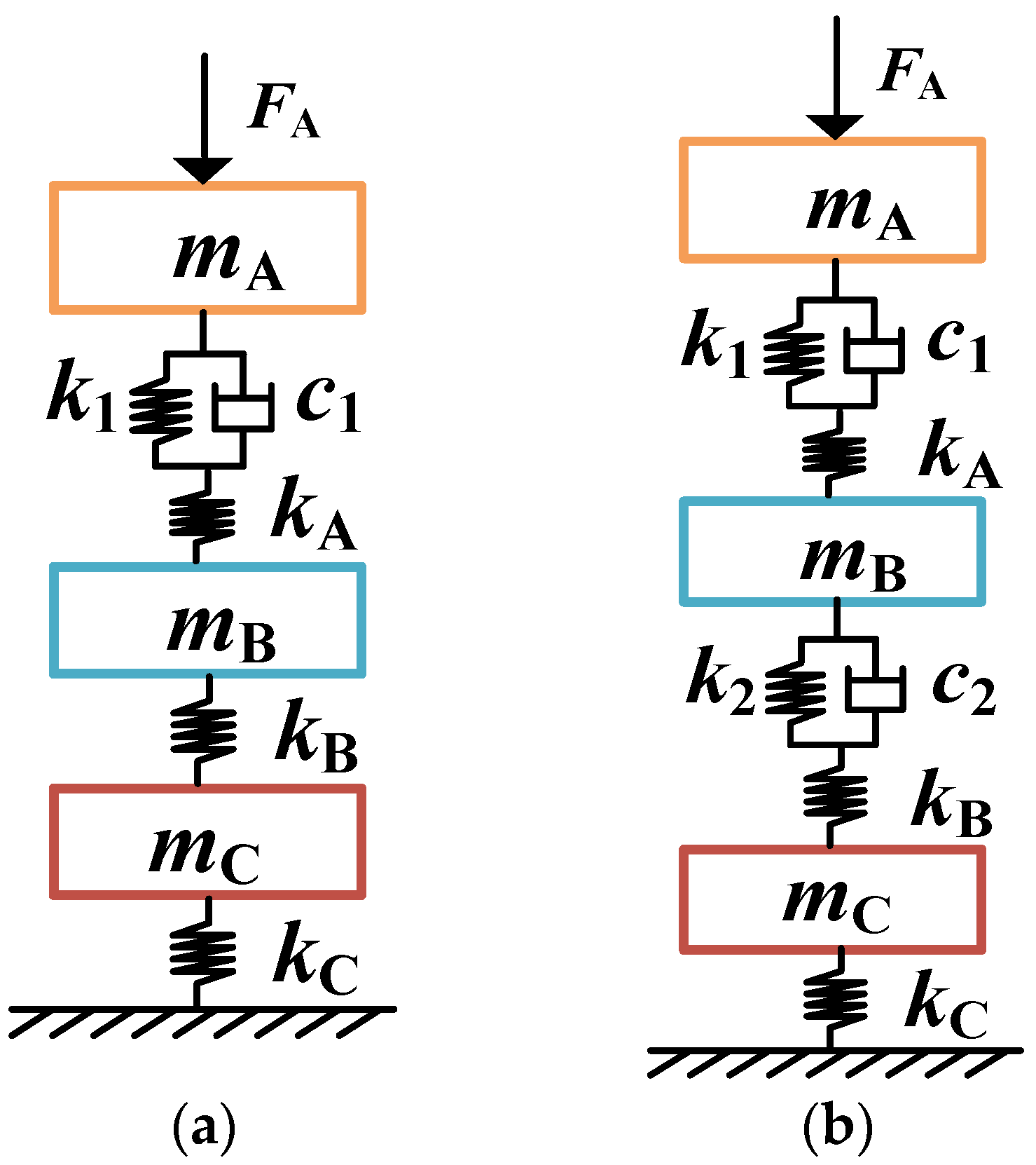
Figure 4 offers the simplified structure of the vibration isolation system of the AUG. Figure 4a shows the AUG with the single-stage vibration isolator. Figure 4b shows the AUG with the two-stage vibration isolator. The AUG is mainly composed of three individual parts (connected by the supporting metal frame), i.e., the power system, the battery and the wing. In Figure 4, mA, mB and mC denote the mass of the power system, the battery and the wing in the AUG, respectively. The first-order vibration isolator is installed between the power system and the battery, and the second-order vibration isolator is installed between the battery and the wing.
In the dynamic modeling of the vibration isolation system, the power system is typically assumed to connect to a rigid foundation by the vibration isolator. In the modelling of underwater vehicles, the deck of the shaft is treated as a rigid foundation with infinite mass and stiffness. Obviously, this assumption is not physically accurate. Considering the influence of the stiffness and mass of the foundation, the elastic foundation could be identified by a mass–spring system. For the studied AUG, the power system, battery and wing are modularly connected. Therefore, a three-degrees-of-freedom mass–spring system is established considering the stiffness of the power system, battery and wing in the dynamic modelling. Figure 5 displays the dynamic models of the vibration isolation system of the AUG. Figure 5a shows the single-stage vibration isolator. Figure 5b shows the two-stage vibration isolator. In Figure 5, kA, kB, kC, k1 and k2 denote the stiffness of power system, the battery, the wing, the first-order vibration isolator and the second-order vibration isolator in the AUG, respectively. c1 and c2 denote the damping of the first-order vibration isolator and the second-order vibration isolator in the AUG, respectively.
According to the dynamic theory [45], the dynamic equation of the AUG with the vibration isolator is
M x ¨ + C x ˙ + K x = F
where M, C and K are the mass matrix, damping matrix and stiffness matrix, respectively; F is the excitation force vector, and x is the displacement vector. According to the vibration isolation theory, the damping could be ignored, as it does not affect the isolation frequency band; thus, Equation (1) is simplified as
M x ¨ + K x = F
The excitation force F is simplified to the harmonic excitation, as it can be used to formulate most of the excitation forces in the power system. Therefore, x is the steady-state response of Equation (1) under harmonic excitation. F and x are expressed as
F = [ F A e i ω t , 0 , 0 ] T
x = [ x A e i ( ω t φ ) , x B e i ( ω t φ ) , x C e i ( ω t φ ) ] T
By putting Equations (3) and (4) into Equation (2), the following equation could be
Z D x = F
where ZD = −ω2M + K, and ZD is the displacement impedance or dynamic stiffness. The displacement response of the dynamic system is
x = Z D 1 F
The force transmission ratio is an evaluation index of the vibration isolation system. The force transmission ratio in the dynamic model of the AUG could be treated as the ratio of the force of the wing and the excitation force, which is given as
H ( ω ) = | F C F A | = | k C x C F A |
The force transmission ratio is normally expressed as the logarithm form:
η = 20 lg | H ( ω ) |
where the unit of η is dB.
The mass matrix and stiffness matrix of the dynamic model of the AUG with the single-stage vibration isolator are defined as
M 1 = [ m A m B m C ] , K 1 = [ k 1 k A k 1 + k A k 1 k A k 1 + k A k 1 k A k 1 + k A k 1 k A k 1 + k A + k B k B k B k B + k C ]
The mass matrix and stiffness matrix of the dynamic model of the AUG with the two-stage vibration isolator are obtained as
M 2 = [ m A m B m C ] , K 2 = [ k 1 k A k 1 + k A k 1 k A k 1 + k A k 1 k A k 1 + k A k 1 k A k 1 + k A + k 2 k B k 2 + k B k 2 k B k 2 + k B k 2 k B k 2 + k B k 2 k B k 2 + k B + k C ]

3.2. Simulation Results from Dynamic Models

3.2.1. Force Transmission Ratio

In this section, the numerical analysis cases of the force transmission ratios of the single- and two-stage vibration isolation of the AUG are calculated using a MATLAB code by solving the dynamic Equations (2)–(8). The influences of the stiffness of the rubber ring, the power system, the battery and the wing on the vibration isolation effect are considered in the following analysis.
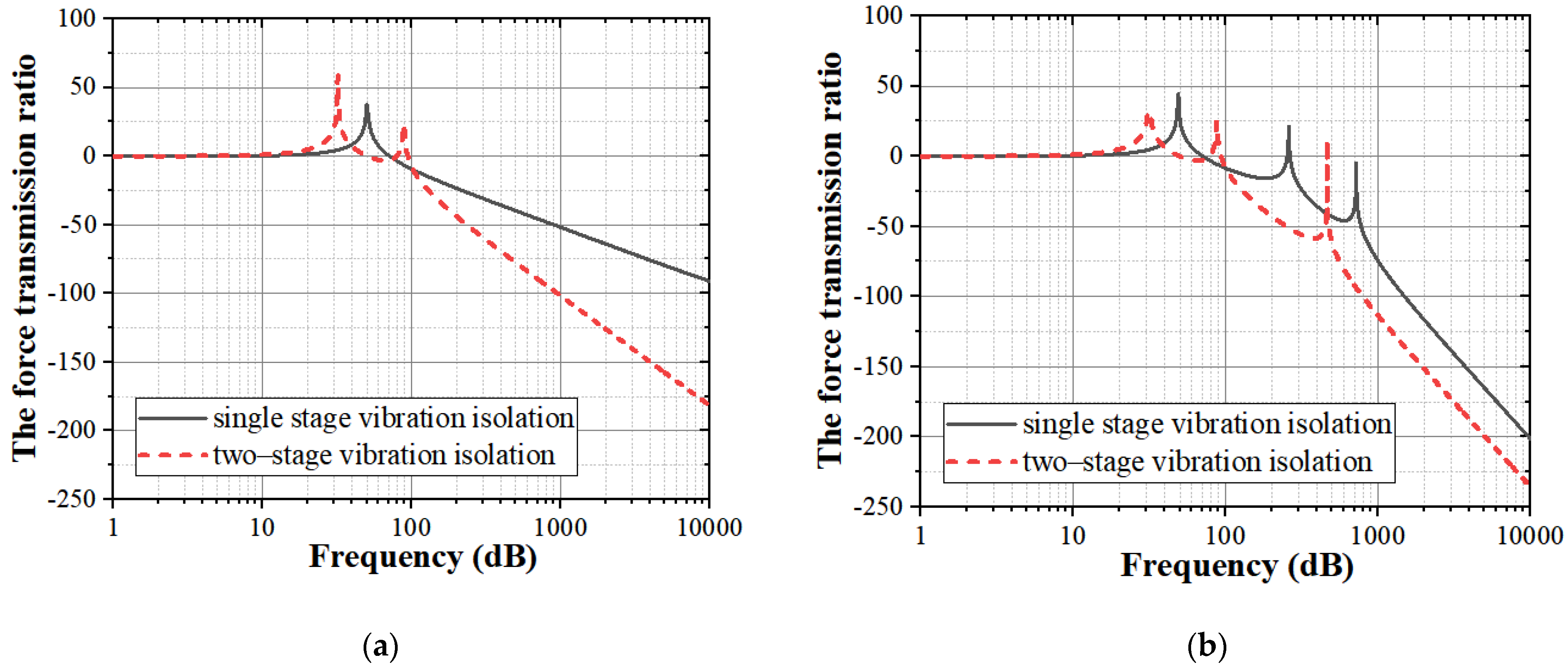
Figure 6a shows the force transmission ratio of the vibration isolation system of the AUG without considering the structure stiffness. Figure 6b shows the cases considering the structure stiffness. In this case, mA, mB and mC are 100 kg, 80 kg and 60 kg respectively. kA, kB and kC are 5 × 10⁸ N/m, 5 × 10⁸ N/m and 5 × 10⁸ N/m respectively. The stiffnesses of the first- and second-order vibration isolators (k1 and k2) are 1 × 10⁷ N/m. In Figure 6, the two-stage vibration isolation has a much lower force transmission ratio at a high frequency. Assuming the original body as the rigid body, one and two peaks in the force transmission ratios of the single- and two-stage vibration isolation are observed, respectively. However, when the structure stiffness is considered, the peak numbers of the single- and two-stage vibration isolation are three. In addition, the force transmission ratio is much lower when the structural stiffness is considered.

3.2.2. Influence of the Isolator Stiffness

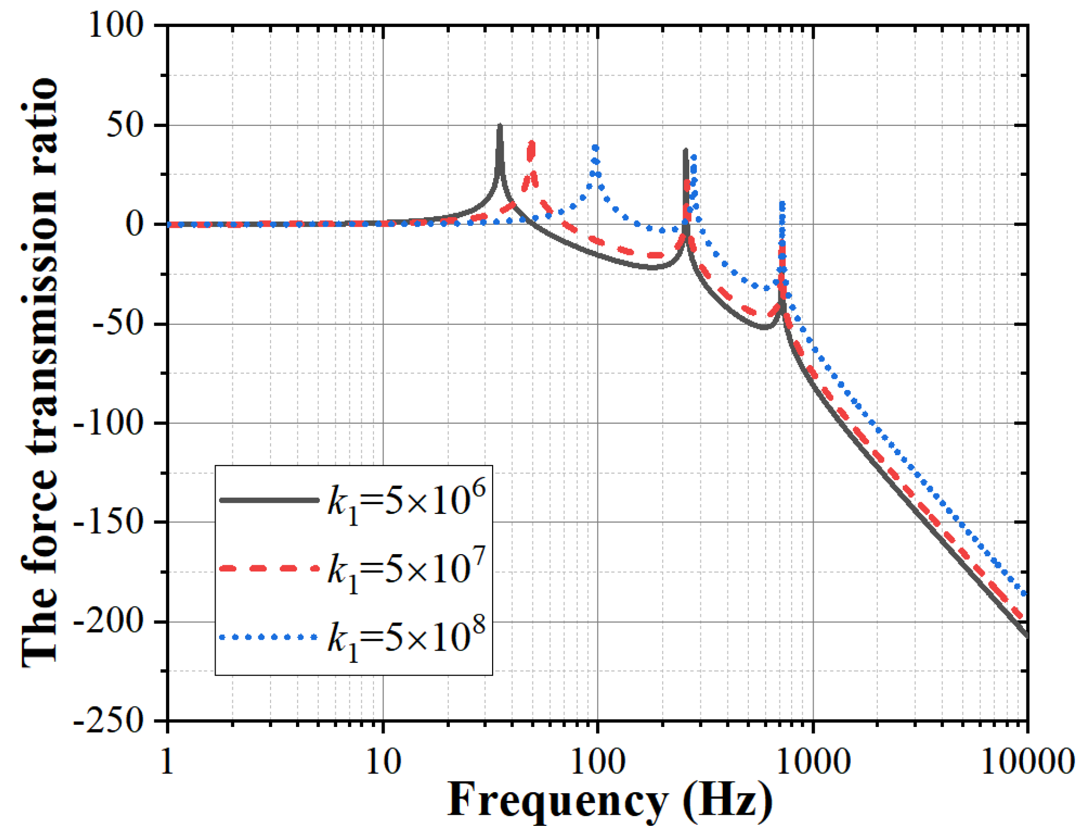
In the modelling method of the single- and two-stage vibration isolation system of the AUG, k1 and k2 respectively denote the stiffness of the first-order and second-order isolator, which are the O-shaped rubber ring and the C-shaped rubber ring, respectively. Figure 7 shows the influence of k1 on the force transmission ratios of the single-stage vibration isolation. Figure 8a shows the influence of k1 on the force transmission ratios of the two-stage vibration isolation. Figure 8b shows the influence of k2 on the force transmission ratios of the two-stage vibration isolation. In Figure 7 and Figure 8, the isolator stiffness is a significant influence factor of the vibration isolation system. According to vibration isolation theory, the peak frequency of the vibration isolation system decreases with the isolator stiffness. In Figure 7, the first peak frequency decreases with k1 while the other peak frequencies are unchanged. In Figure 8, the first and second peaks’ frequencies decrease with k1 and k2, while the other peak frequencies are unchanged.

3.2.3. Influence of the Structure Stiffness of the Power System, the Battery and the Wing

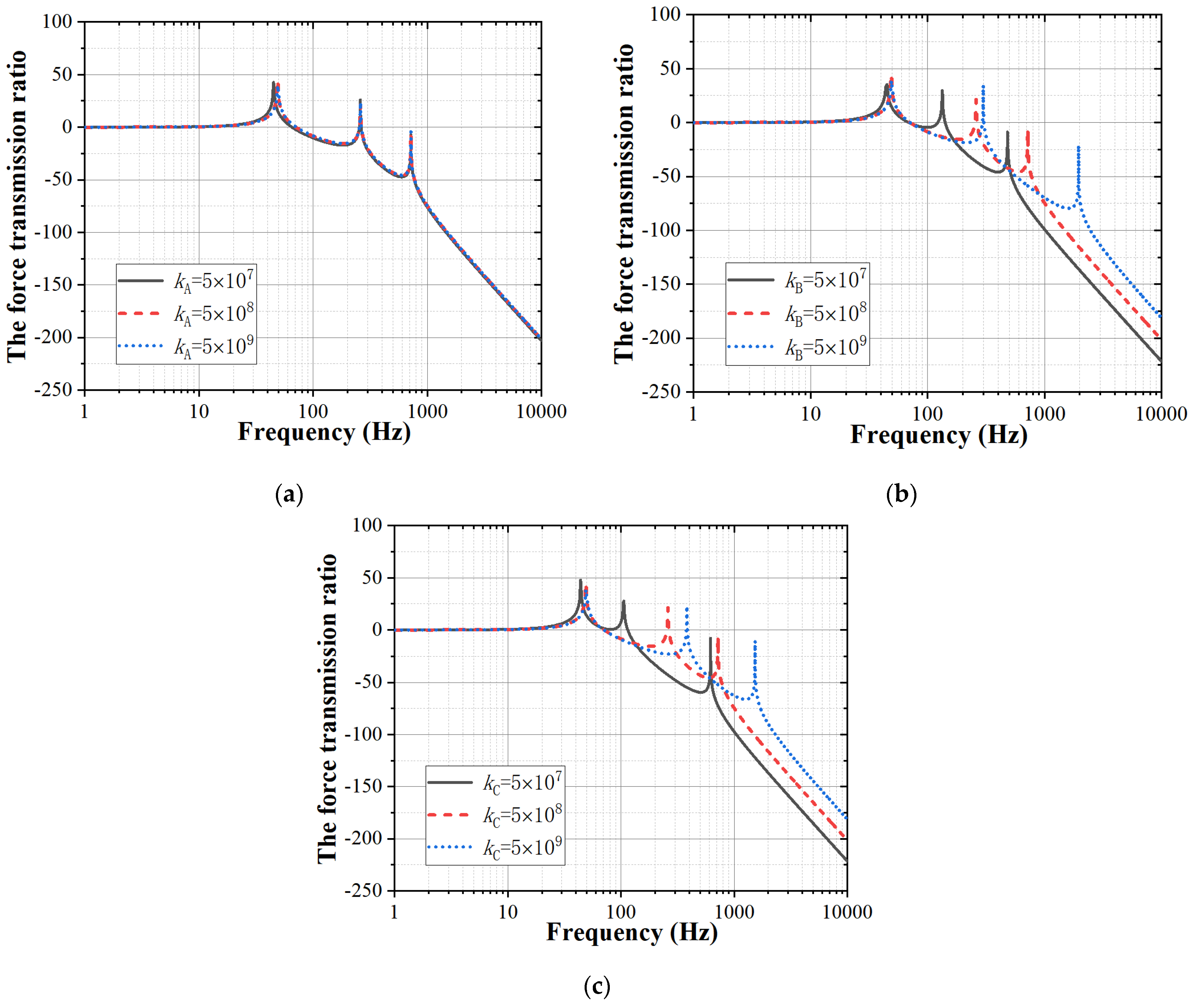
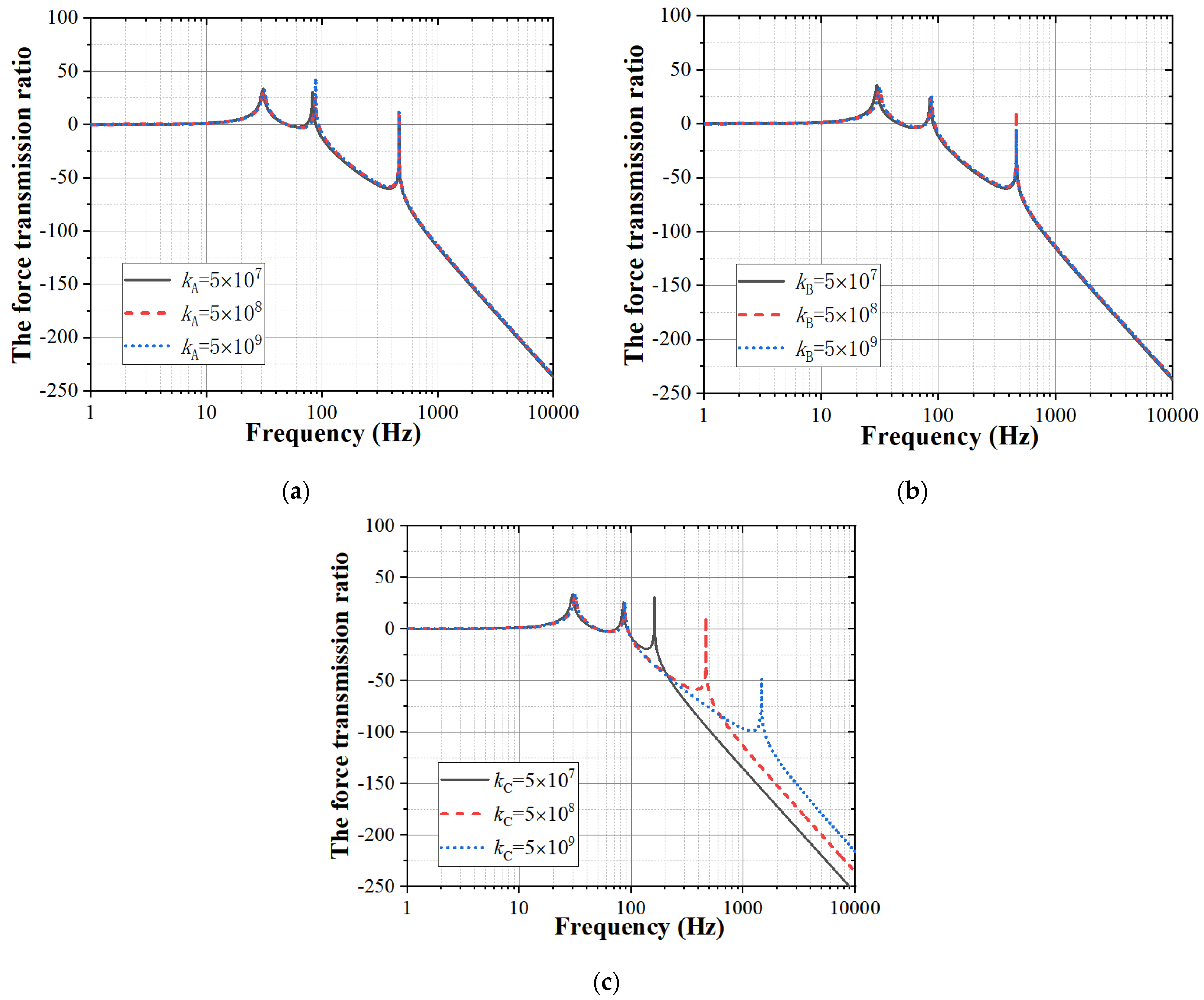
According to the vibration isolation theory, the force transmission ratio is affected by the stiffness of the structure. In the dynamic model of the AUG, the stiffness parameters are kA, kB, kC, k1 and k2. The influences of kA, kB, and kC on the force transmission ratios of the AUG are discussed in the following cases. Figure 9 and Figure 10 show the influences of kA, kB, and kC on the force transmission ratios of the single- and two-stage vibration isolation in the AUG. Figure 9a–c is the influence of structure stiffness on the single-stage vibration system. Figure 10a–c shows the influence of the structure stiffness on the two-stage vibration system. According to Figure 9 and Figure 10, kB and kC can affect the force transmission ratio of the single-stage vibration isolation, while kA is ineffective; kC can affect the force transmission ratio of the two-stage vibration isolation, while kA and kB are ineffective; the force transmission ratio of the single-stage vibration isolation decreases with kB and kC; the force transmission ratio of the two-stage vibration isolation decreases with kC; the peak of the force transmission ratio moves to a low frequency with the lowering of kC.
The reasons for the above results are that kA is in a series connection with k1, and kB is in a series connection with k2. Therefore, the smaller stiffnesses of k1 and k2 make major impacts in series connection with other stiffness parameters. In the single-stage vibration system, the effective parameters kB and kC could be regarded as the supporting stiffness. Similarly, in the two-stage vibration system, the effective parameter kC could also be regarded as the supporting stiffness. It can be concluded that the supporting stiffness has the main influence on the vibration isolation effect. In addition, the force transmission ratio decreases with the supporting stiffness.

4. Finite Element Analysis of the Vibration Isolation of the AUG

4.1. Dynamic Stiffness Analysis of the Rubber Ring Isolator

Dynamic stiffnesses are essential parameters in the design of a vibration isolation system. According the results discussed in Section 3, the vibration isolation frequency decreases with the dynamic stiffness of the vibration isolator. Dynamic stiffness, also known as displacement impedance, is the ability of the structure to resist deformation under a dynamic load. Ignoring the influence of structural damping, the dynamic equation of the rubber ring isolator subjected to dynamic load is (11)
[ M ] { x ¨ } + [ K ] { x } = { f }
where [M] and [K] are the mass matrix and stiffness matrix of the vibration isolator, {x} is the acceleration vector of the vibration isolator, and {f} is the force matrix of the vibration isolator. Supposing that the excitation force is {f} = {F*}eiωt, the displacement response of the vibration isolator is {x} = {X}eiωt. Equation (11) can be written as follows:
( ω 2 [ M ] + [ K ] ) { X } = { F }
Thus, the dynamic stiffness [KD] of the vibration isolator is
[ K D ] = ω 2 [ M ] + [ K ]
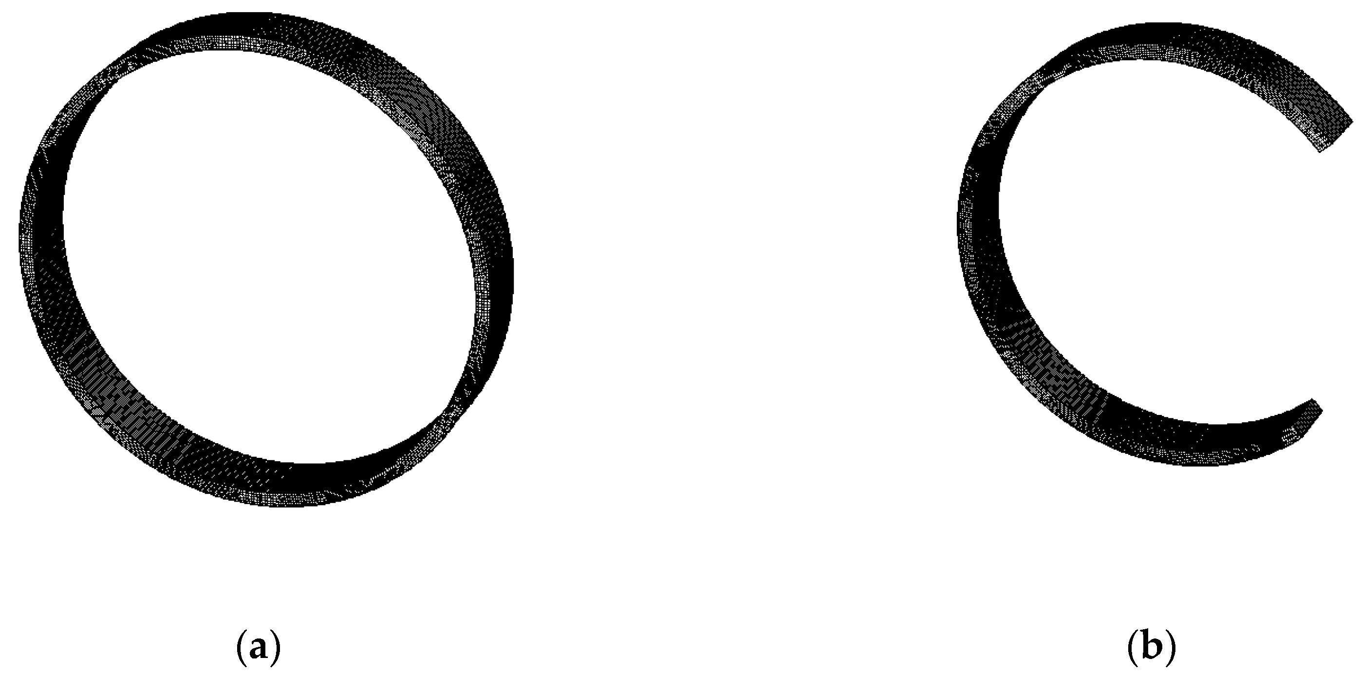
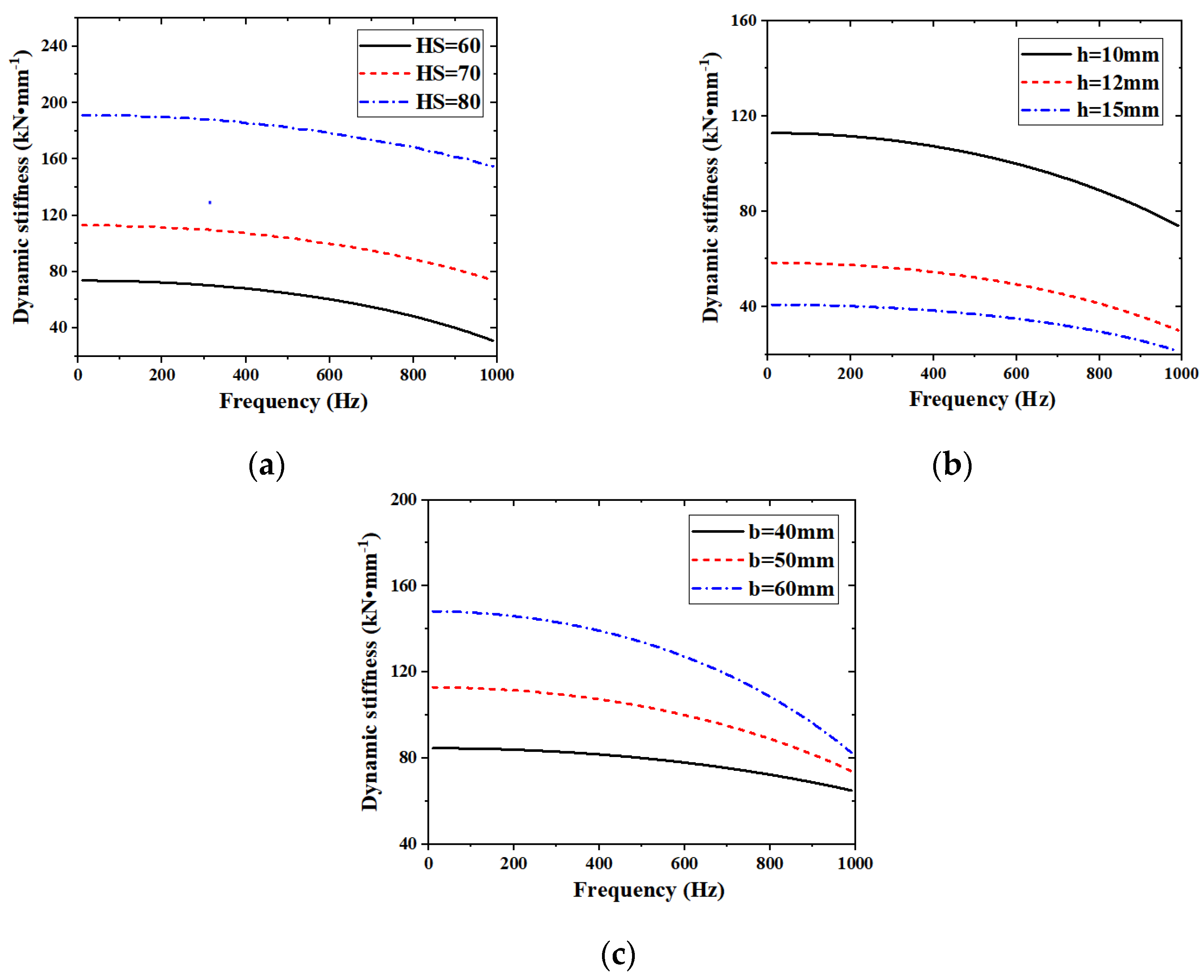
Figure 11 is the finite element model meshing diagrams for the rubber ring vibration isolator, in which Figure 11a is the meshing diagram of the first-stage vibration isolator, and Figure 11b is that of the second-stage vibration isolator. In this paper, the dynamic stiffness parameters of the rubber vibration isolation ring structure were calculated using the frequency domain solver finite element method in the COMSOL Multiphysics software. The outer ring surface of the vibration isolation ring is set as a fixed boundary, and the inner ring surface of the vibration isolation ring is set as a displacement load. The frequency domain range of the dynamic stiffness calculation is from 10 Hz to 1000 Hz. Hexahedral mesh is adopted. The mesh number of the finite element model of the first stage isolator is 81,500. The mesh number of the finite element model of the second stage isolator is 61,125. The properties of rubber materials are close to those of polymer hyperelastic materials. Therefore, the two-parameter Mooney Rivlin hyperelastic materials model is employed as the rubber material model. In addition, the material parameter calculation methods of the two-parameter Mooney Rivlin hyperelastic materials model are illustrated in Equations (14)–(18).
W E = C 10 ( I 1 3 ) + C 01 ( I 1 3 ) + K 0 2 ( J 1 ) 2
C 01 = 0.25 C 10
E = 6 ( C 01 + C 10 )
E = 15.75 + 2.15 H a 100 H a
K 0 = E 3 ( 1 2 ν )
where WE is the strain energy; C01 and C10 are the material parameters; and K0, E, Ha and ν are the bulk modulus, the Young’s modulus, the hardness and the Poisson ratio of the material, respectively. When Ha is defined, other meterial parameters such as E, C01, C10 and K0 can be solved step by step by following Equations (15)–(18). In the structural design of the vibration isolator for the AUG, the hardness of the rubber material, and the width and thickness of the rubber ring are the design parameters for the dynamic stiffness adjustment. A parametric analysis is carried out in order to discuss the impact of the design parameters on the dynamic stiffness.
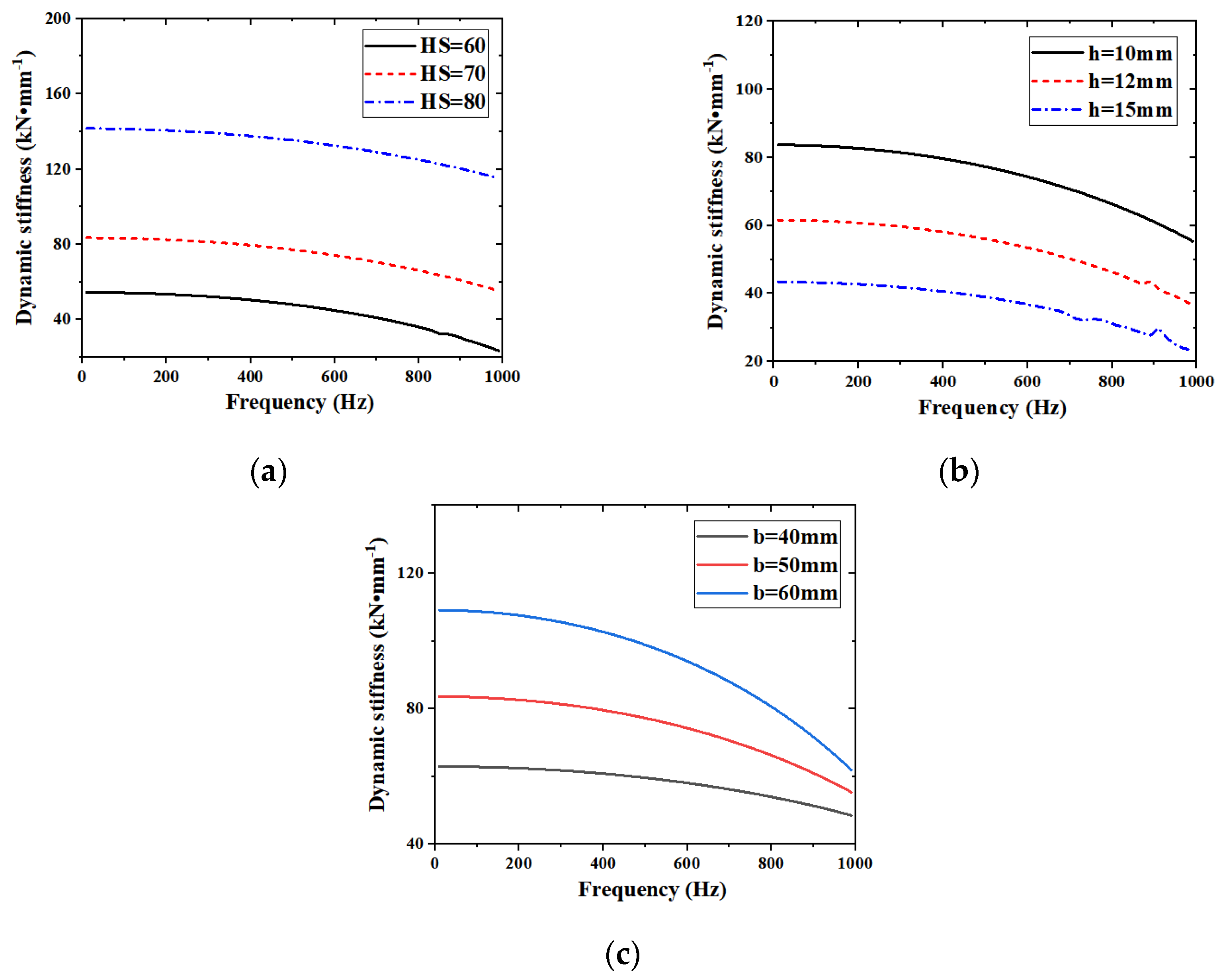
Figure 12 presents the dynamic stiffness of the first-stage isolator of the underwater gliding power device. Figure 13 displays the dynamic stiffness of the second-stage isolator of the underwater gliding power device. In Figure 12 and Figure 13, the symbols HS, h and b donate the hardness, thickness and width, respectively. As can be observed from Figure 12 and Figure 13, the dynamic stiffness of the vibration isolator ring made of hyperelastic rubber material decreases with the increase of the frequency. The dynamic stiffness of the first and second vibration isolators increase with the rubber material’s hardness. The dynamic stiffness of the first and second vibration isolators decrease with the ring thickness and increase with the ring width. With the increase of the frequency, the difference of the dynamic stiffness of the vibration isolation ring with different hardness HS and thickness h parameters remains basically unchanged, while the difference of the dynamic stiffness of the vibration isolation ring with different width b parameters gradually decreases. Therefore, in the design stage of the vibration isolator, materials and dimensions are vital parameters for stiffness adjustment.

4.2. Coupled Vibro-Acoustic Finite Element Model

When the AUG is operating underwater, a portion of the fluid surrounding the structure should be coupled. The interaction of the heavy fluid and structure could be considered as the added apparent mass in the dynamic modeling. In the simulation of the underwater structure, the fluid–structure coupling model and the acoustic–structure coupling model are two general methods for the analysis of the interaction of the structure and fluid. In this section, the acoustic–structure coupling model is established with the finite element method. The fluid is regarded as the acoustic compressible domain. The influence of the fluid on the structure is represented by the sound pressure load applied to the structure’s surface. The governing equation of the acoustic domain is the Helmholtz equation, which is given as
2 p + k 2 p = 0
where p is the acoustic pressure and k is the wave number. ∇2 is the Laplacian operator. The finite element acoustic discretization of Equation (19) is
M A p ¨ + K A p = 0
where MA is the acoustic mass matrix and KA is the acoustic stiffness matrix. The damping term is not concerned.
The coupled vibro-acoustic finite element method solving the acoustic wave equation and structural dynamic equation simultaneously is defined as
[ M S 0 M AS M A ] { x ¨ p ¨ } + [ K S K AS 0 K A ] { x p } = { F 0 }
where MS and KS are the mass matrix and stiffness matrix of structure. MAS is the acoustic–structure coupled mass matrix. KAS is the acoustic–structure coupled stiffness matrix. x is the displacement of the structure. F is the excitation force applied in the structure.
The radiated sound power W and sound power level Lw are calculated as
W = 1 2 Re p v dS
L w = 10 log 10 W W ref
where v is the conjugate of the acoustic velocity. Wref is the reference sound power, and its value is 10−12 W.
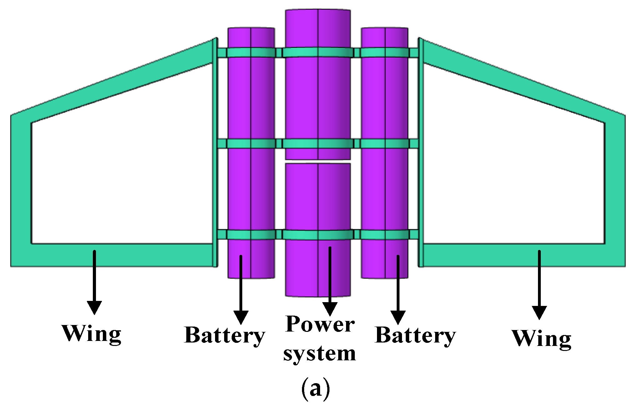
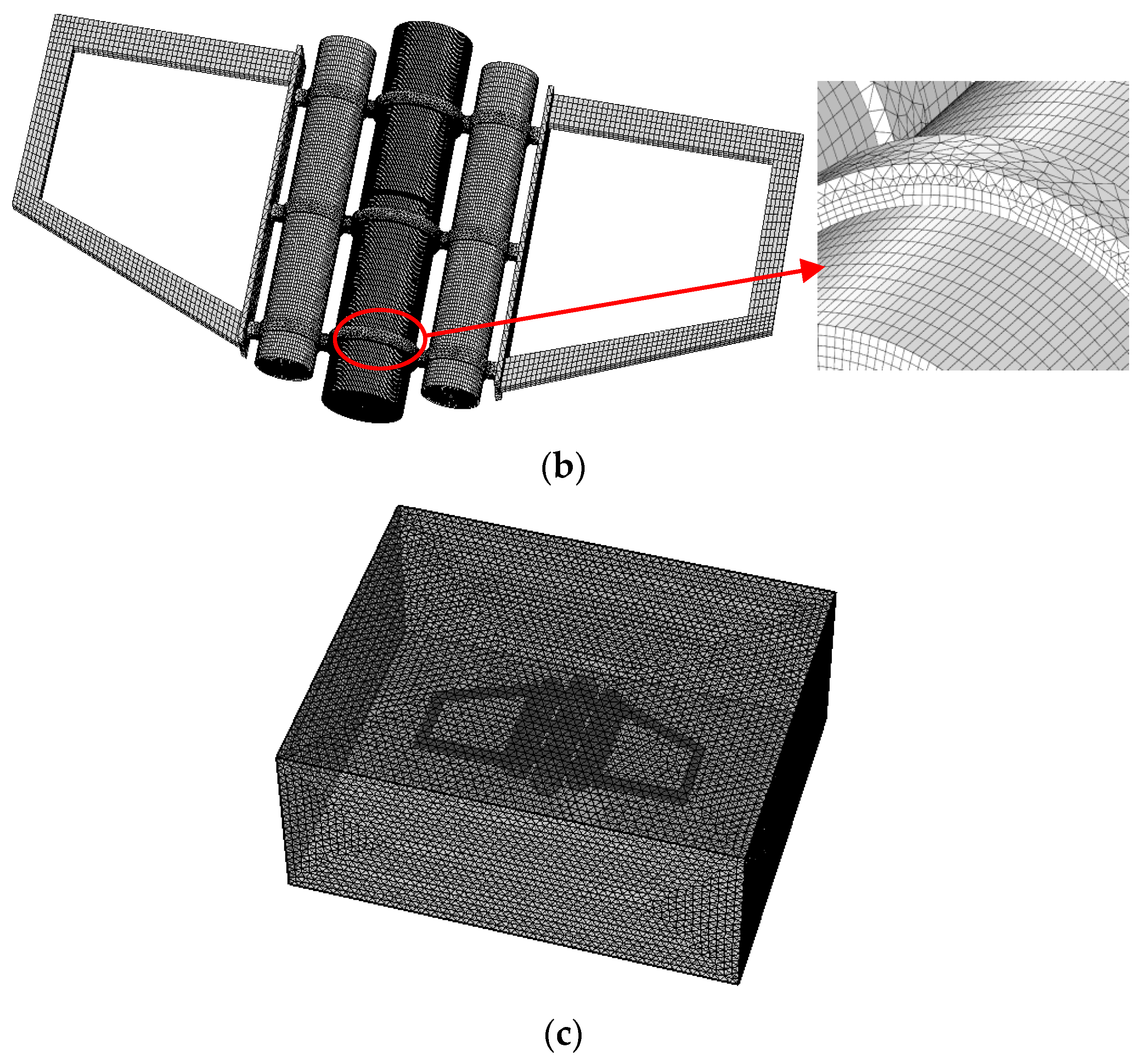
The finite element model of the AUG is demonstrated in Figure 14. Figure 14a shows the finite element model of the AUG. Figure 14b is the meshing picture. Figure 14c shows the acoustic–structure coupling finite element model of the AUG. In Figure 14a, the layout of the power system, the battery and the wing are disclosed. The vibration is transmitted from the power system to the battery and the wing. In Figure 14b, the mesh type in the finite element models is the hybrid grid of free tetrahedral mesh and hexahedral mesh. The models of the AUG in air and the AUG in water have about 580,000 elements and 1,150,000 elements, respectively. The maximum and minimum mesh sizes are 0.02 m and 0.005 m, respectively. The force excitation applied in the power system of the AUG is harmonic excitation with a frequency band from 10 Hz to 2000 Hz. The constraint displacement boundary conditions of the AUG are free. The extracted vibration response of the AUG is the front surface of the wing. The material parameters of the AUG structure and rubber ring vibration isolator are listed in Table 1, in which all of the materials are linear elastic without considering the damping, in order to distinguish the vibration isolation effect from the damping effect.

4.3. Vibration and Sound Responses of the Single- and Two-stage Vibration Isolation

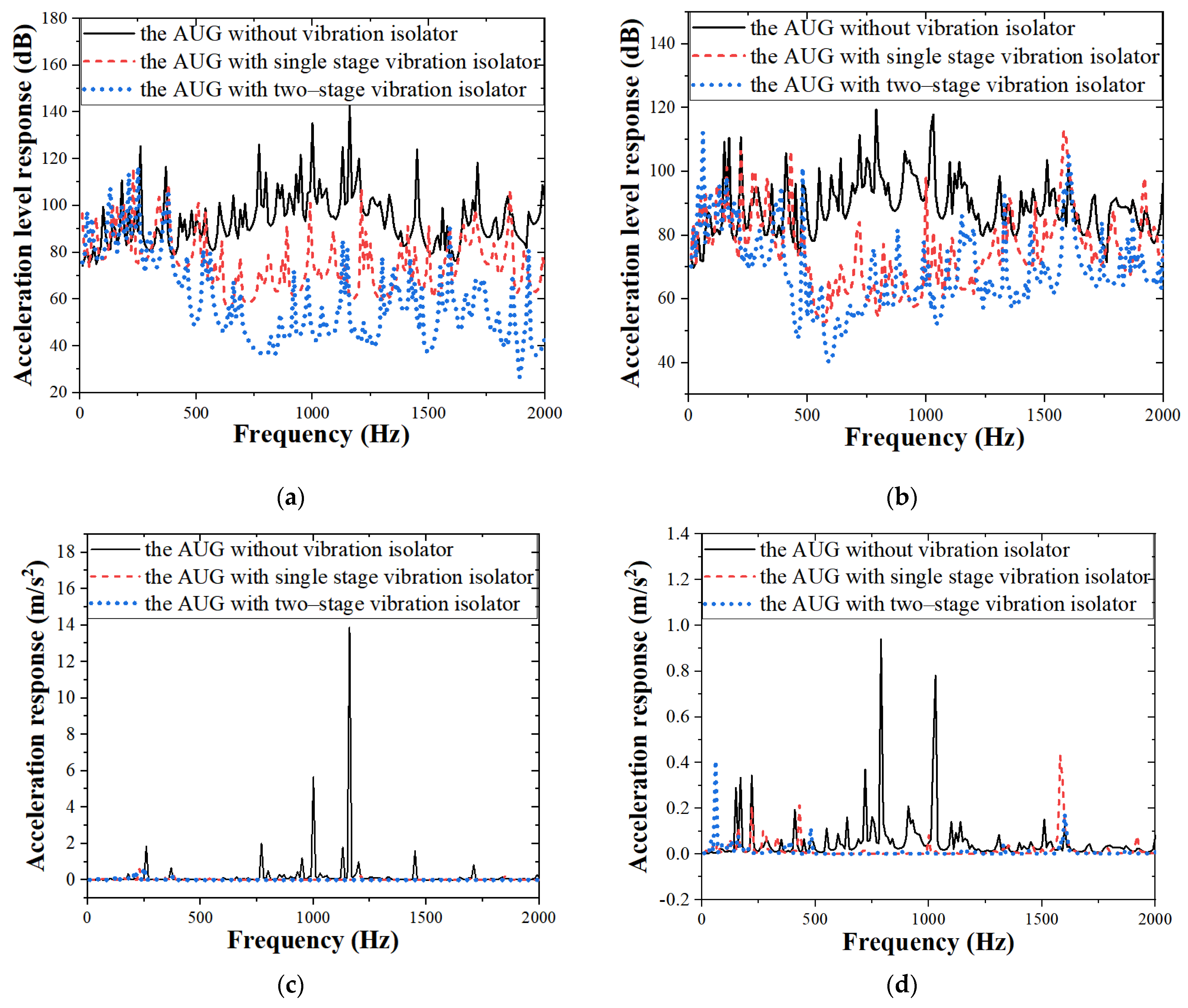
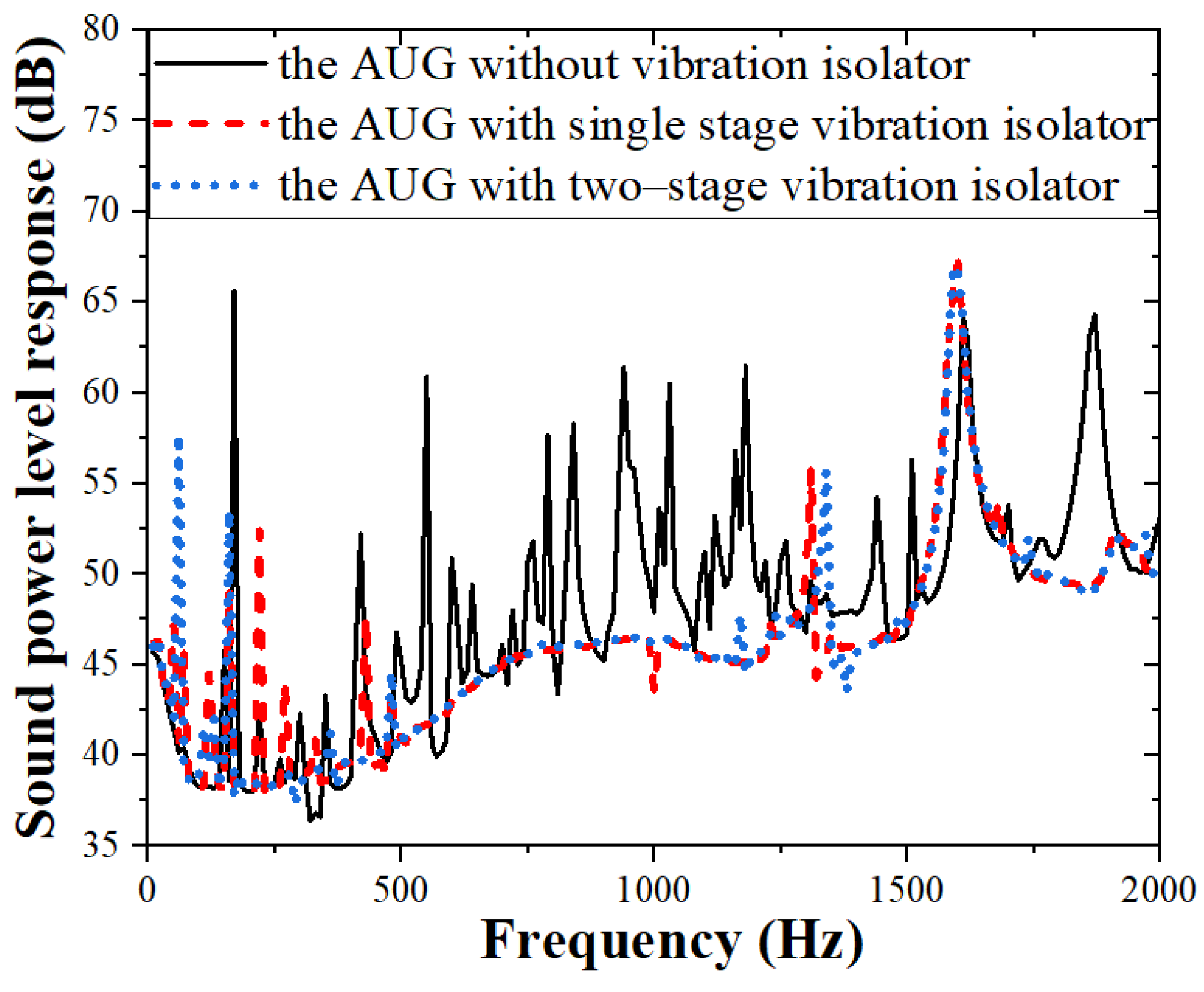
In order to verify the application effect of vibration control with the single- and two-stage vibration isolation on the power system of the AUG, the finite element models of the AUG with single- and two-stage vibration isolators are respectively analyzed. Figure 15 conveys the acceleration frequency responses of the AUG with the single- and two-stage vibration isolators compared with the AUG without the vibration isolator. Figure 15a shows the vibration frequency response of the AUG in air. Figure 15b shows the vibration frequency response of the AUG in water. As seen in Figure 15, the shape decline appears in the acceleration responses of the AUG with the single stage and two-stage vibration isolators in the frequency band above 400 Hz. The acceleration response both in air and water of the AUG with the two-stage vibration isolator declines more than that of the AUG with the single-stage vibration isolator. The result trends of the finite element models are in agreement with those of the dynamic model in Section 3. Figure 16 shows the sound power level frequency response of the AUG in water. As presented in Figure 16, the sound power levels of the AUG with the single- and two-stage vibration isolators decrease tremendously in the middle frequency. The sound power level peaks disappear in the frequency band of 500–1250 Hz. The results imply that a rubber ring vibration isolator is an effective method in controlling the self-noise of the AUG caused by the power system.

4.4. Insertion Loss of the Single- and Two-Stage Vibration Isolation

The insertion loss is quoted as a major evaluation index of a vibration isolation system in engineering application. The insertion loss is generally investigated in the design stage, and is calculated as
L = 20 lg ( x x 0 )
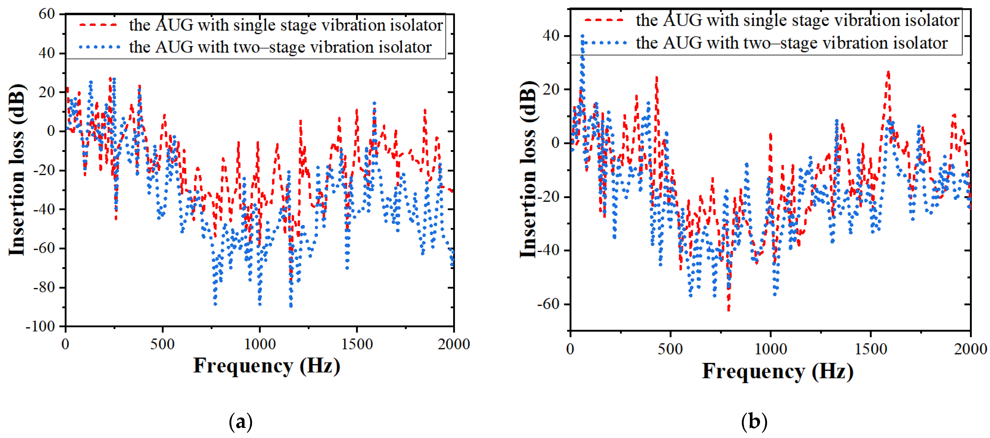
where x is the vibration response of the AUG with the vibration isolator, and x0 is the vibration response of the AUG without the vibration isolator. Figure 17 presents the insertion loss of the AUG with a single- and two-stage vibration isolator in air and in water, respectively. The insertion loss trend of the AUG in water is similar to the trend in the air. The insertion loss comes down vastly above the frequency of 400 Hz, implying the vibration control effect of the rubber ring vibration isolation. Besides this, the insertion loss of the AUG with the two-stage vibration isolation is smaller than that of the single-stage vibration isolation in air and in water.

5. Conclusions

A new two-stage rubber ring vibration isolator for the AUG was proposed. The vibration isolation performances of the single- and two-stage vibration isolation systems for the AUG were investigated in both the theoretical method and finite element method. The dynamic stiffnesses of the rubber ring isolator with different design parameters were calculated. A vibro-acoustic finite element analysis was carried out, considering the influence of the apparent mass of water. The sound radiation reduction provided by the application of a rubber ring isolator was discussed. The main conclusions can be summarized as follows. (1) The vibration isolation effects of the AUG in both air and water with the two-stage vibration isolation perform better than those of the AUG with the single-stage vibration isolation. (2) The stiffnesses of the battery and wing affect the force transmission ratio of the single-stage vibration isolation system, and the stiffness of the wing affects the force transmission ratio of the two-stage vibration isolation system in the AUG. These affecting structure stiffnesses could be regarded as the supporting stiffness of the vibration isolation system in the AUG. (3) The dynamic stiffness of the first and second vibration isolators can be adjusted using various material and dimensional parameters. (4) The application of the single- and two-stage vibration isolators in an AUG could tremendously decrease the sound radiation in water. The self-noise of the AUG could be controlled using the rubber ring vibration isolator proposed in this paper.

Author Contributions

Conceptualization, J.L.; methodology, Y.L.; software, Y.L.; validation, Y.L.; formal analysis, Y.L. and J.L.; investigation, Y.L. and J.L.; resources, Y.L.; data curation, Y.L.; writing—original draft preparation, Y.L.; writing—review and editing, J.L.; visualization, Q.H. and L.G.; supervision, G.P.; project administration, G.P. and Q.H.; funding acquisition, G.P. All authors have read and agreed to the published version of the manuscript.

Funding

This research was funded by the National Key Research and Development Plan of China 2020YFB1313200, National Natural Science Foundation of China, grant number 52175120, and Fundamental Research Funds for Central Universities, grant number 3102020HHZY030001.

Data Availability Statement

Some of the data and models generated during the study are available from the corresponding author by reasonable request.

Conflicts of Interest

The authors have no conflicts of interest to this work.

References

  1. Jenkins, S.A.; D’Spain, D. Autonomous underwater gliders. In Springer Handbook of Ocean Engineering, 1st ed.; Springer International Publishing: New York, NY, USA, 2016; Volume 9, pp. 301–322. [Google Scholar]
  2. Rudnick, D.L.; Davis, R.E.; Eriksen, C.C.; Fratantoni, D.M.; Perry, M.J. Underwater gliders for ocean research. Mar. Technol. Soc. J. 2004, 38, 73–84. [Google Scholar] [CrossRef]
  3. Ullah, B.; Ovinis, M.; Baharom, M.B.; Javaid, M.Y.; Izhar, S.S. Underwater gliders control strategies: A review. In Proceedings of the Control Conference, Kota Kinabalu, Malaysia, 3 June 2015. [Google Scholar]
  4. Javaid, M.Y.; Ovinis, M.; Nagarajan, T.; Hashim, F.B.M. Underwater gliders: A review. MATEC Web Conf. 2014, 13, 02020. [Google Scholar] [CrossRef]
  5. Rudnick, D.L. Ocean Research Enabled by Underwater Gliders. Annu. Rev. Mar. Sci. 2016, 8, 519–541. [Google Scholar] [CrossRef] [PubMed]
  6. Zhang, S.; Yu, J.; Zhang, A.; Zhang, F. Spiraling motion of underwater gliders: Modeling, analysis, and experimental results. Ocean Eng. 2013, 60, 1–13. [Google Scholar] [CrossRef]
  7. Fan, S.; Woolsey, C.A. Dynamics of underwater gliders in currents. Ocean Eng. 2014, 84, 249–258. [Google Scholar] [CrossRef]
  8. Wang, C.; Yuan, M. Research on the Ambient Noise Observation Technology Based on the Underwater Glider. Acoust. Aust. 2021, 49, 485–493. [Google Scholar] [CrossRef]
  9. Ferguson, B.G.; Lo, K.W.; Rodgers, J.D. Sensing the underwater acoustic environment with a single hydrophone onboard an undersea glider. In Proceedings of the Oceans’10 IEEE Sydney, Sydney, Australia, 24–27 May 2010; pp. 1–5. [Google Scholar]
  10. Liu, J.; Xu, Y.; Pan, G. A combined acoustic and dynamic model of a defective ball bearing. J. Sound Vib. 2021, 501, 116029. [Google Scholar] [CrossRef]
  11. Shi, Z.; Liu, J.; Li, H.; Zhang, Q.; Xiao, G. Dynamic simulation of a planet roller bearing considering the cage bridge crack. Eng. Fail. Anal. 2022, 131, 105849. [Google Scholar] [CrossRef]
  12. Liu, J.; Tang, C.; Pan, G. Dynamic modeling and simulation of a flexible-rotor ball bearing system. J. Vib. Control 2021. [Google Scholar] [CrossRef]
  13. Liu, J.; Tang, C.; Wu, H.; Xu, Z.; Wang, L. An analytical calculation method of the load distribution and stiffness of an angular contact ball bearing. Mech. Mach. Theory 2019, 142, 103597. [Google Scholar] [CrossRef]
  14. Liu, J.; Xu, Z. A simulation investigation of lubricating characteristics for a cylindrical roller bearing of a high-power gearbox. Tribol. Int. 2022, 167, 107373. [Google Scholar] [CrossRef]
  15. Song, D.L.; Zhang, C.L.; Nie, Y.L.; Zhu, Y.X.; Shi, Y.X. Research on the turbulence observation platform based on underwater glider. J. Ocean. Technol. 2015, 35, 1–5. [Google Scholar]
  16. Wang, C.; Han, M.; Sun, Q.; Lan, S. Noise measurement and optimization of underwater acoustic glider platform. J. Unmanned Undersea Syst. 2020, 28, 396–402. [Google Scholar]
  17. Liu, C.; Jing, X.; Daley, S.; Li, F. Recent advances in micro-vibration isolation. Mech. Syst. Signal Process. 2015, 56–57, 55–80. [Google Scholar] [CrossRef]
  18. Ibrahim, R.A. Recent advances in nonlinear passive vibration isolators. J. Sound Vib. 2008, 314, 371–452. [Google Scholar] [CrossRef]
  19. Ravindra, B.; Mallik, A.K. Performance of non-linear vibration isolators under harmonic excitation. J. Sound Vib. 1994, 170, 325–337. [Google Scholar] [CrossRef]
  20. Yilmaz, C.; Kikuchi, N. Analysis and design of passive low-pass filter-type vibration isolators considering stiffness and mass limitations. J. Sound Vib. 2006, 293, 171–195. [Google Scholar] [CrossRef]
  21. Kari, L. On the dynamic stiffness of preloaded vibration isolators in the audible frequency range: Modeling and experiments. J. Acoust. Soc. Am. 2003, 113, 1909–1921. [Google Scholar] [CrossRef]
  22. Majak, J.; Pohlak, M. Decomposition method for solving optimal material orientation problems. Compos. Struct. 2010, 92, 1839–1845. [Google Scholar] [CrossRef]
  23. Jazar, R.; Narimani, A.; Golnaraghi, M.; Swanson, D. Practical Frequency and Time Optimal Design of Passive Linear Vibration Isolation Mounts. Veh. Syst. Dyn. 2003, 39, 437–466. [Google Scholar] [CrossRef]
  24. Majak, J.; Pohlak, M.; Eerme, M.; Velsker, T. Design of car frontal protection system using neural networks and genetic algorithm. Mechanics 2012, 18, 453–460. [Google Scholar] [CrossRef] [Green Version]
  25. Song, Y.; Wen, J.; Yu, D.; Liu, Y.; Wen, X. Reduction of vibration and noise radiation of an underwater vehicle due to propeller forces using periodically layered isolators. J. Sound Vib. 2014, 333, 3031–3043. [Google Scholar] [CrossRef]
  26. Yang, Y.; Pan, G.; Yin, S.; Yuan, Y.; Huang, Q. Verification of vibration isolation effectiveness of the underwater vehicle power plant. J. Mar. Sci. Eng. 2021, 9, 382. [Google Scholar] [CrossRef]
  27. Liu, S.-Y.; Yu, X.; Zhu, S.-J. Study on the chaos anti-control technology in nonlinear vibration isolation system. J. Sound Vib. 2008, 310, 855–864. [Google Scholar] [CrossRef]
  28. Liu, N.; Li, C.; Yin, C.; Dong, X.; Hua, H. Application of a dynamic antiresonant vibration isolator to minimize the vibration transmission in underwater vehicles. J. Vib. Control 2018, 24, 3819–3829. [Google Scholar] [CrossRef]
  29. Yu, N.; Ouyang, H.; Zhang, J.; Ye, J.; Yan, Q.; Zheng, X. Performance analyses of passive vibration isolator with parallel connection of quasi-zero stiffness and inerter dampers. Appl. Sci. 2020, 10, 6894. [Google Scholar] [CrossRef]
  30. Yan, L.; Gong, X. Experimental study of vibration isolation characteristics of a geometric anti-spring isolator. Appl. Sci. 2017, 7, 711. [Google Scholar] [CrossRef] [Green Version]
  31. Zhang, J.; Richards, C.M. Parameter identification of analytical and experimental rubber isolators represented by Maxwell models. Mech. Syst. Signal Process. 2007, 21, 2814–2832. [Google Scholar] [CrossRef]
  32. Gil-Negrete, N.; Vinolas, J.; Kari, L. A simplified methodology to predict the dynamic stiffness of carbon-black filled rubber isolators using a finite element code. J. Sound Vib. 2006, 296, 757–776. [Google Scholar] [CrossRef]
  33. Jin, J.; Zhang, Z.; Xiong, X. Dynamic stiffness calculation method for rubber ring isolator. Torpedo Technol. 2012, 20, 125–128. [Google Scholar]
  34. Moore, S. Analytical modelling of single and two-stage vibration isolation systems. In Proceedings of the ACOUSTICS 2011, Gold Coast, Australia, 2–4 November 2011; p. 116. [Google Scholar]
  35. Li, J.; Zhang, Z.; Xu, H.; Feng, Z. Dynamic characteristics of the vibratory roller test-bed vibration isolation system: Simulation and experiment. J. Terramechanics 2014, 56, 139–156. [Google Scholar] [CrossRef]
  36. Wang, X.; Zhou, J.; Xu, D.; Ouyang, H.; Duan, Y. Force transmissibility of a two-stage vibration isolation system with quasi-zero stiffness. Nonlinear Dyn. 2016, 87, 633–646. [Google Scholar] [CrossRef]
  37. Lu, Z.; Yang, T.; Brennan, M.J.; Li, X.; Liu, Z. On the performance of a two-stage vibration isolation system which has geometrically nonlinear stiffness. J. Vib. Acoust. 2014, 136, 064501. [Google Scholar] [CrossRef]
  38. Pan, J.; Hansen, C. Total power flow from a vibrating rigid body to a thin panel through multiple elastic mounts. J. Acoust. Soc. Am. 1992, 92, 895–907. [Google Scholar] [CrossRef]
  39. Xie, S.; Wing, S.; Chan, H.L.W.; Choy, P.K.; Liu, P.C.K. Analysis of vibration power flow from a vibrating machinery to a floating elastic panel. Mech. Syst. Signal Process. 2007, 21, 389–404. [Google Scholar] [CrossRef]
  40. Ashrafiuon, H.; Nataraj, C. Dynamic Analysis of Engine-Mount Systems. J. Vib. Acoust. 1992, 114, 79–83. [Google Scholar] [CrossRef]
  41. Puri, R.S.; Morrey, D.; Bell, A.J.; Durodola, J.; Rudnyi, E.B.; Korvink, J. Reduced order fully coupled structural–acoustic analysis via implicit moment matching. Appl. Math. Model. 2009, 33, 4097–4119. [Google Scholar] [CrossRef]
  42. Junge, M.; Brunner, D.; Gaul, L. Solution of the FE-BE coupled Eigenvalue problem for immersed ship-like structures. Int. J. Numer. Meth. Eng. 2011, 87, 664–676. [Google Scholar] [CrossRef]
  43. Peters, H.; Kinns, R.; Kessissoglou, N. Effects of apparent mass on the radiated sound power from fluid-loaded structures. Ocean Eng. 2015, 105, 83–91. [Google Scholar] [CrossRef]
  44. Peters, H.; Kessissoglou, N.; Marburg, S. Modal decomposition of exterior acoustic-structure interaction problems with model order reduction. J. Acoust. Soc. Am. 2014, 135, 2706–2717. [Google Scholar] [CrossRef]
  45. Frolov, K.V.; Furman, F.A.; Rivin, E.I. Applied Theory of Vibration Isolation Systems; Hemisphere Pub. Corp.: New York, NY, USA, 1990. [Google Scholar]
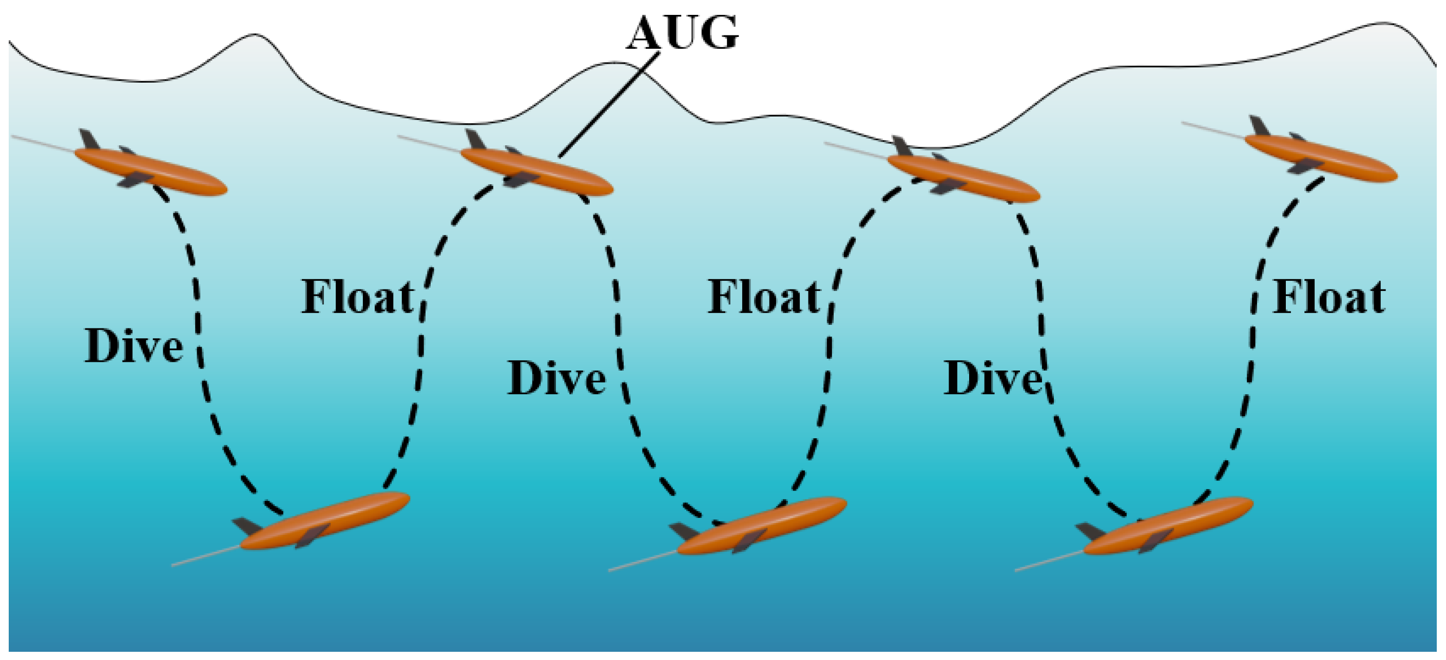
Figure 1. Diagram of the traveling mode of the AUG.
Jmse 10 00162 g001
Figure 2. Diagram of the internal structural layout of the AUG.
Jmse 10 00162 g002
Figure 3. Structure of (a) the single-stage vibration isolator of the power system in the AUG, and (b) the two-stage vibration isolator of the power system in the AUG.
Jmse 10 00162 g003
Figure 4. Simplified structures of the AUG with (a) the single-stage vibration isolator and (b) the two-stage vibration isolator.
Jmse 10 00162 g004
Figure 5. Dynamic models of the AUG with (a) the single-stage vibration isolator and (b) the two-stage vibration isolator.
Jmse 10 00162 g005
Figure 6. The force transmission ratios of the single- and two-stage vibration isolation: (a) without considering the structure stiffness; (b) considering the structure stiffness.
Jmse 10 00162 g006
Figure 7. The force transmission ratios of the single-stage vibration isolation with different isolator stiffnesses.
Jmse 10 00162 g007
Figure 8. The force transmission ratios of the two-stage vibration isolation (a) with different first-order isolator stiffnesses and (b) with different second-order isolator stiffnesses.
Jmse 10 00162 g008
Figure 9. The force transmission ratio of the single-stage vibration isolation with (a) different power system stiffnesses, (b) different battery stiffnesses, and (c) different wing stiffnesses.
Jmse 10 00162 g009
Figure 10. The force transmission ratio of the two-stage vibration isolation with (a) different power system stiffnesses, (b) different battery stiffnesses, and (c) different wing stiffnesses.
Jmse 10 00162 g010
Figure 11. The finite element model meshing of (a) the first-stage vibration isolator, and (b) the second-stage vibration isolator.
Jmse 10 00162 g011
Figure 12. The dynamic stiffness of the first-stage vibration isolator with (a) different material hardnesses, (b) different ring thicknesses, and (c) different ring widths.
Jmse 10 00162 g012
Figure 13. The dynamic stiffness of the second-stage vibration isolator with (a) different material hardnesses, (b) different ring thicknesses, and (c) different ring widths.
Jmse 10 00162 g013
Figure 14. (a) The finite element model of the AUG, (b) the meshing of the AUG, and (c) the acoustic–structure coupling finite element model of the AUG.
Jmse 10 00162 g014aJmse 10 00162 g014b
Figure 15. The acceleration level and acceleration requency responses of the AUG with single- and two-stage vibration isolation: (a) in air; (b) in water; (c) in air; (d) in water.
Jmse 10 00162 g015
Figure 16. The sound power level of the AUG in water.
Jmse 10 00162 g016
Figure 17. The insertion loss of the AUG with single- and two-stage vibration isolation in (a) air and (b) water.
Jmse 10 00162 g017
Table 1. Material parameters of the finite element model.
Material ParametersMaterial TypesDensityYoung’s ModulusPoisson’s Ratio
AUG structureAluminum2780 kg/m37.2 × 1010 Pa0.3
IsolatorRubber1100 kg/m31 × 107 Pa0.49
Publisher’s Note: MDPI stays neutral with regard to jurisdictional claims in published maps and institutional affiliations.