
Dynamic Analysis of an Autonomous Underwater Glider with Single- and Two-Stage Vibration Isolators


Abstract
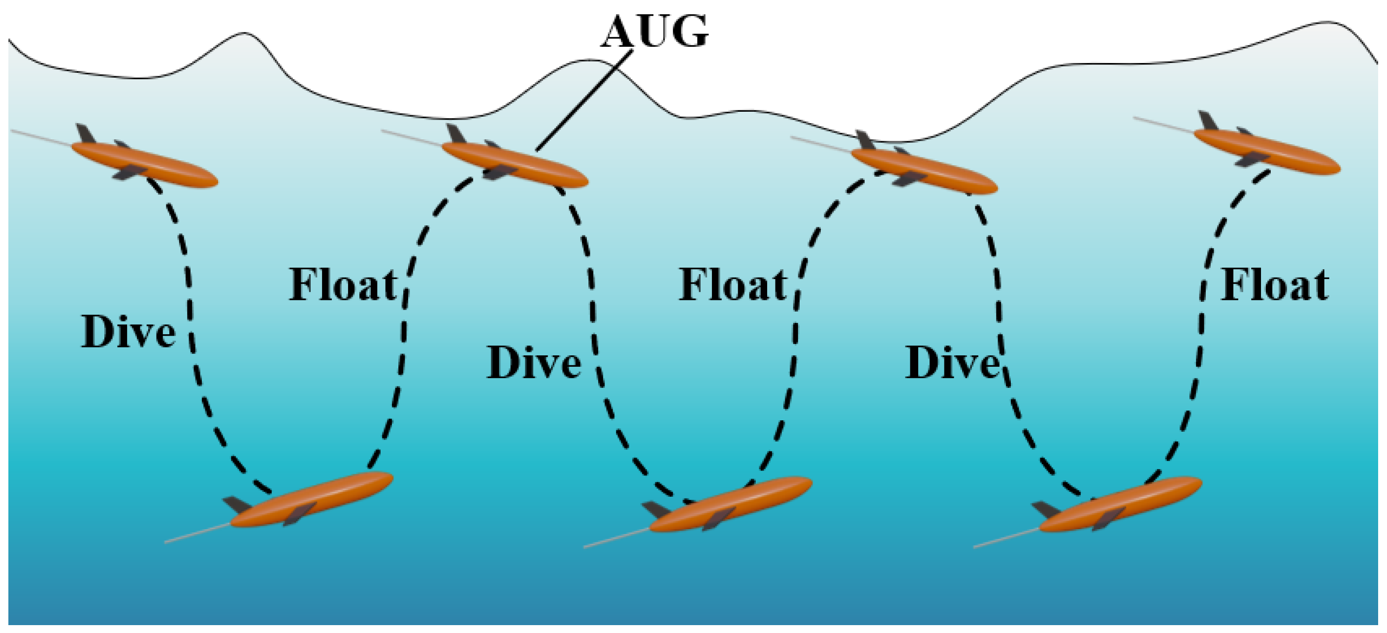
:1. Introduction
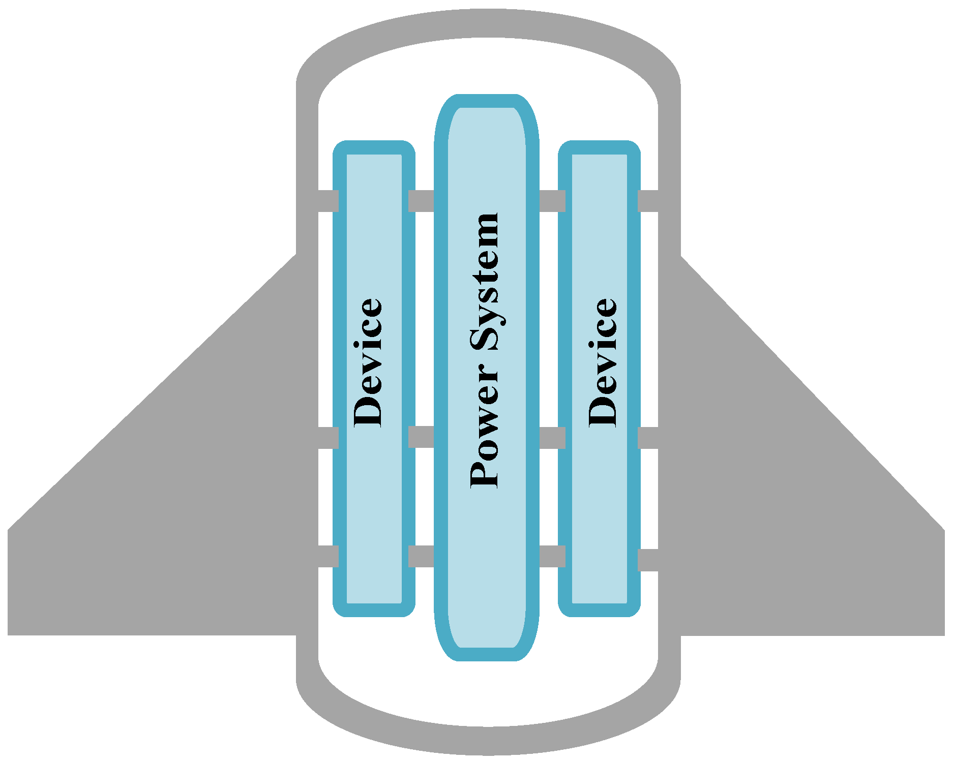
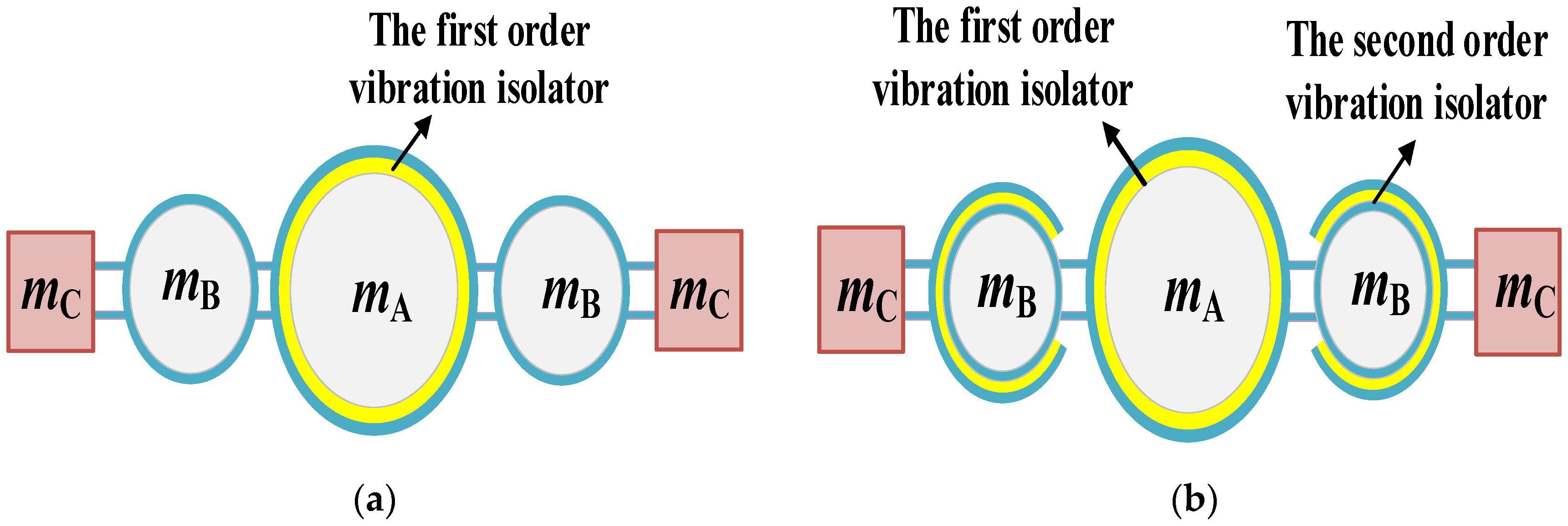
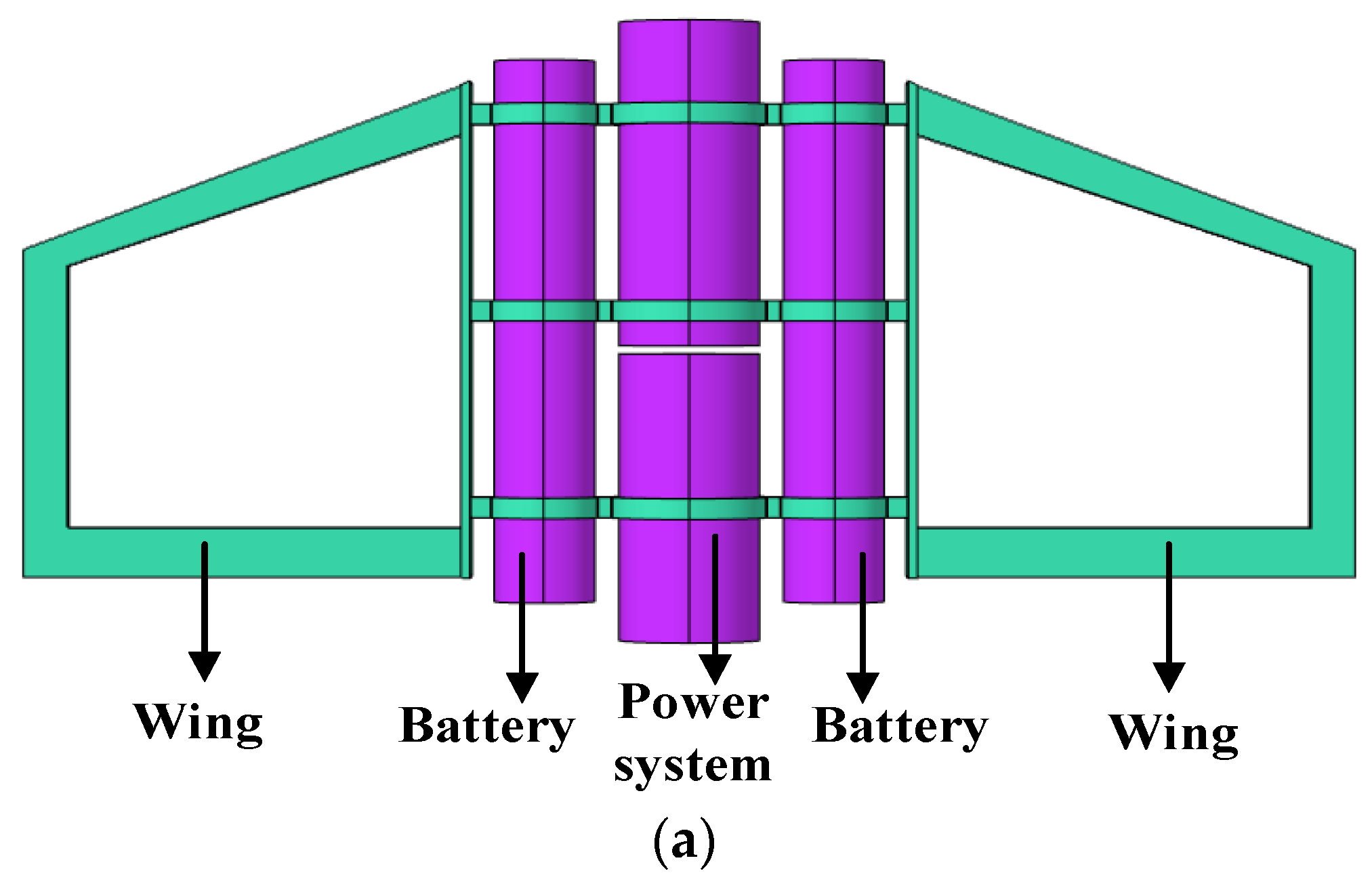
2. Structure Design of the Single- and Two-Stage Vibration Isolation Systems
3. Dynamics Analysis of the AUG with a Vibration Isolation System
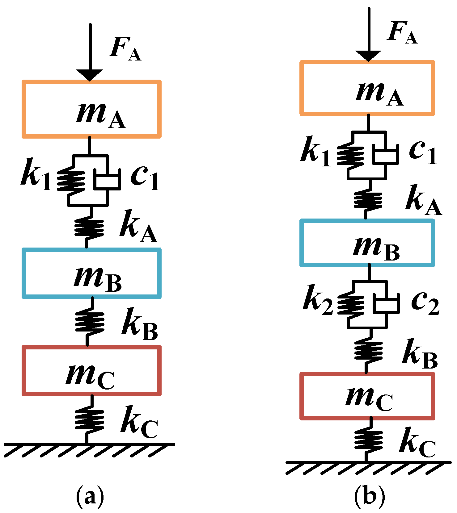
3.1. Dynamic Models
3.2. Simulation Results from Dynamic Models
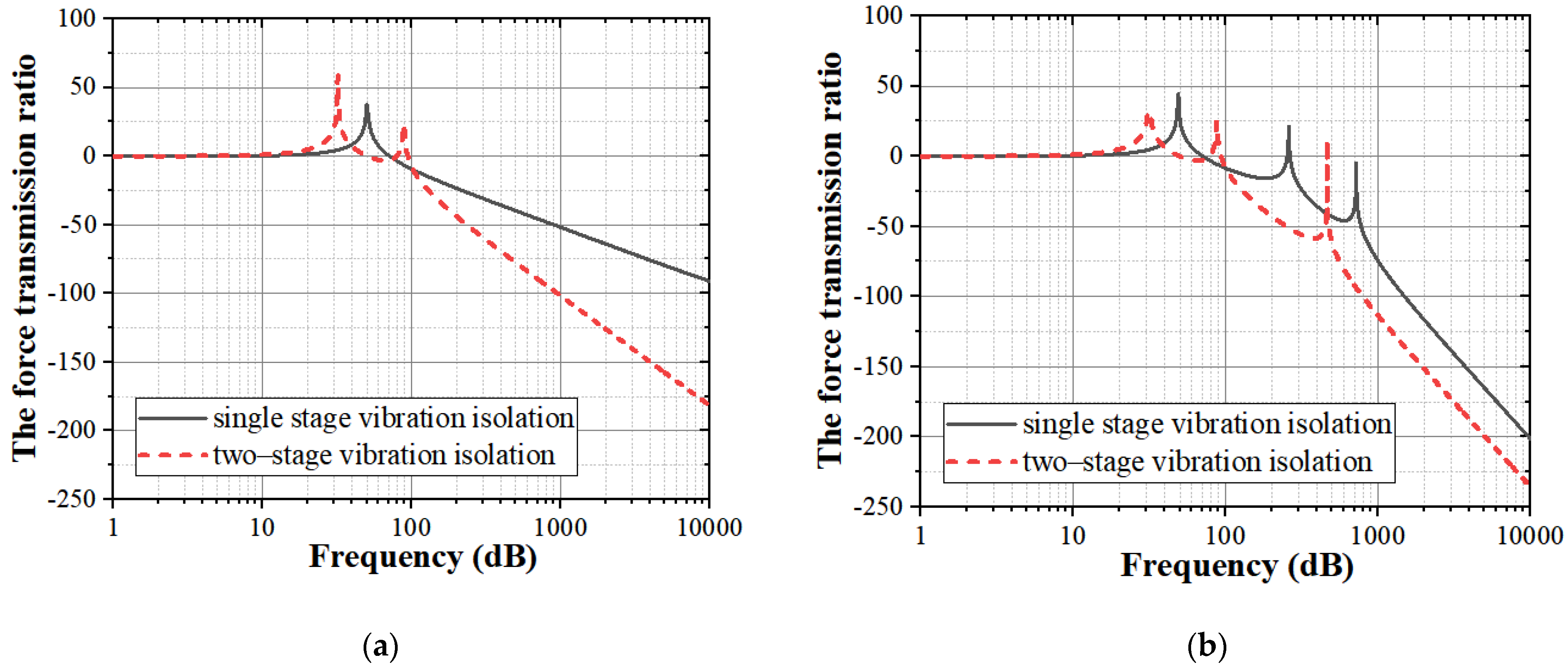
3.2.1. Force Transmission Ratio
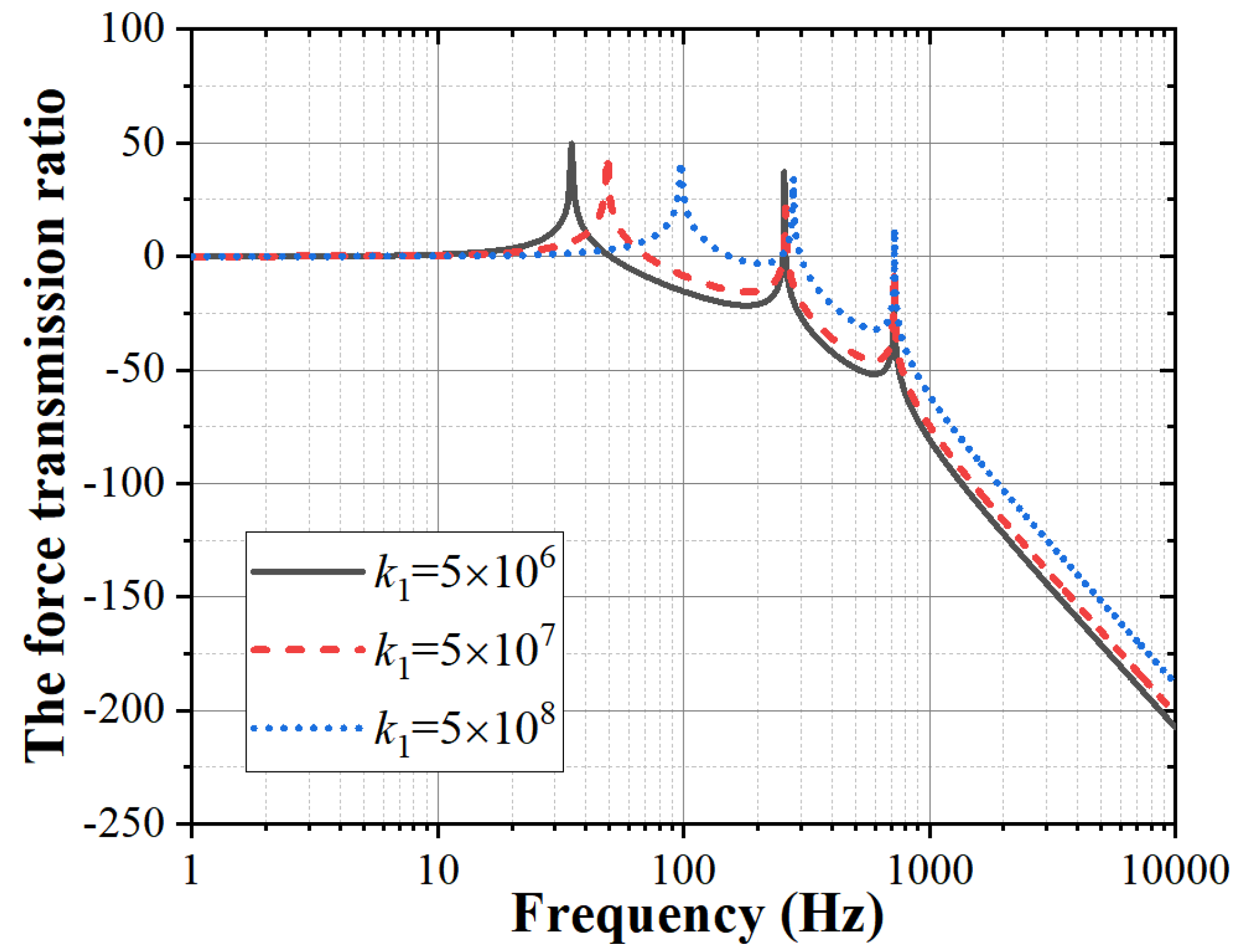
3.2.2. Influence of the Isolator Stiffness
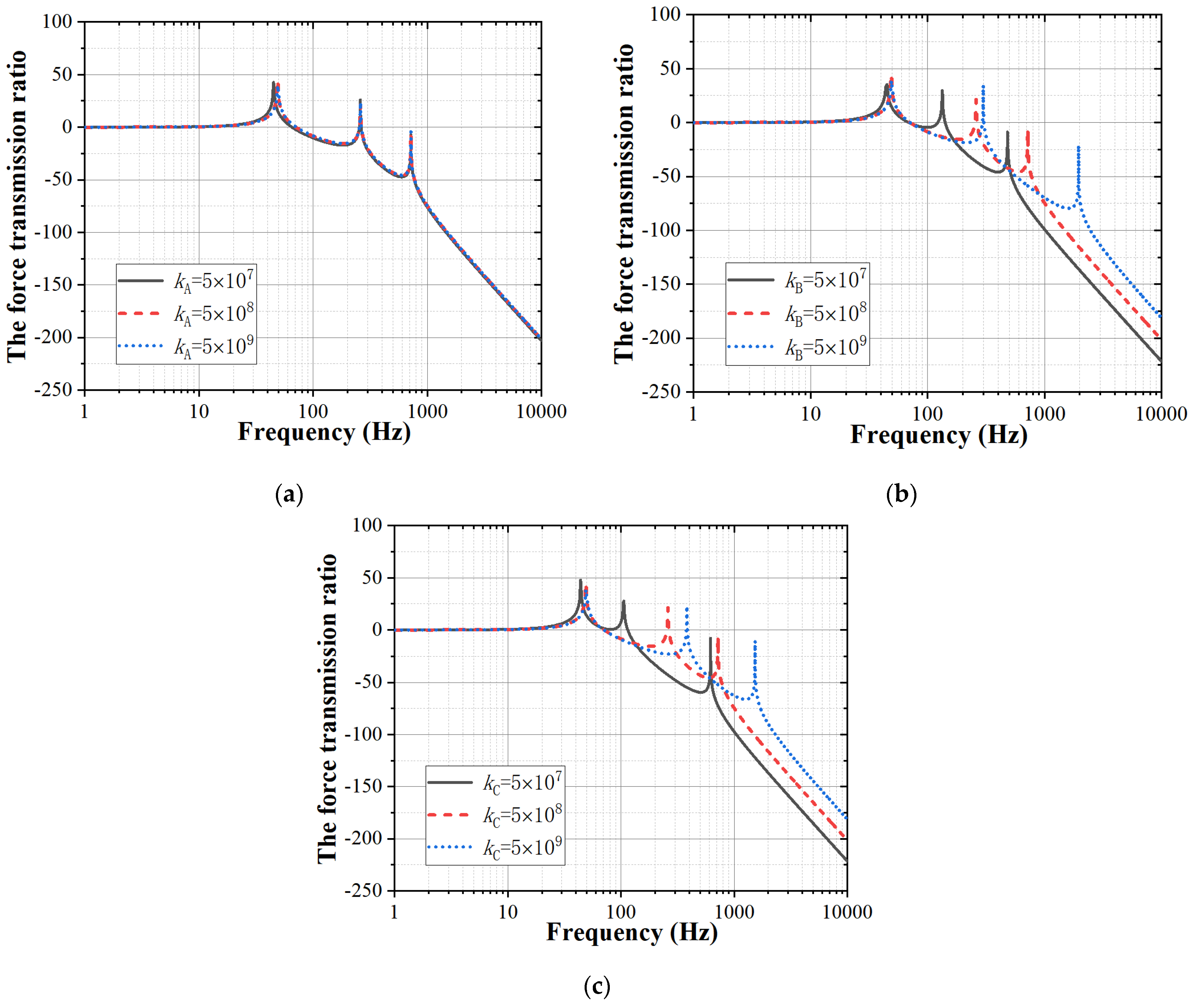
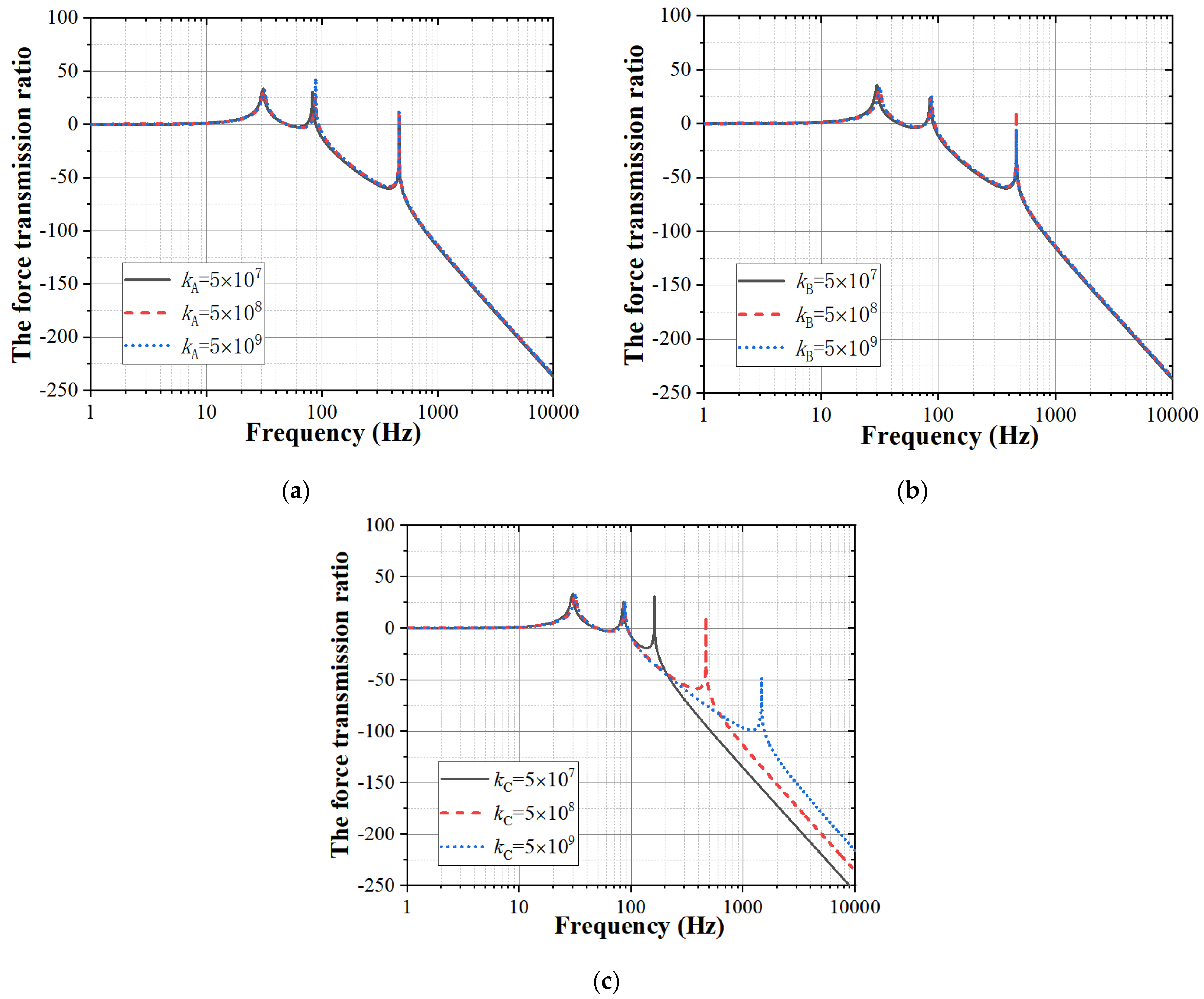
3.2.3. Influence of the Structure Stiffness of the Power System, the Battery and the Wing
4. Finite Element Analysis of the Vibration Isolation of the AUG
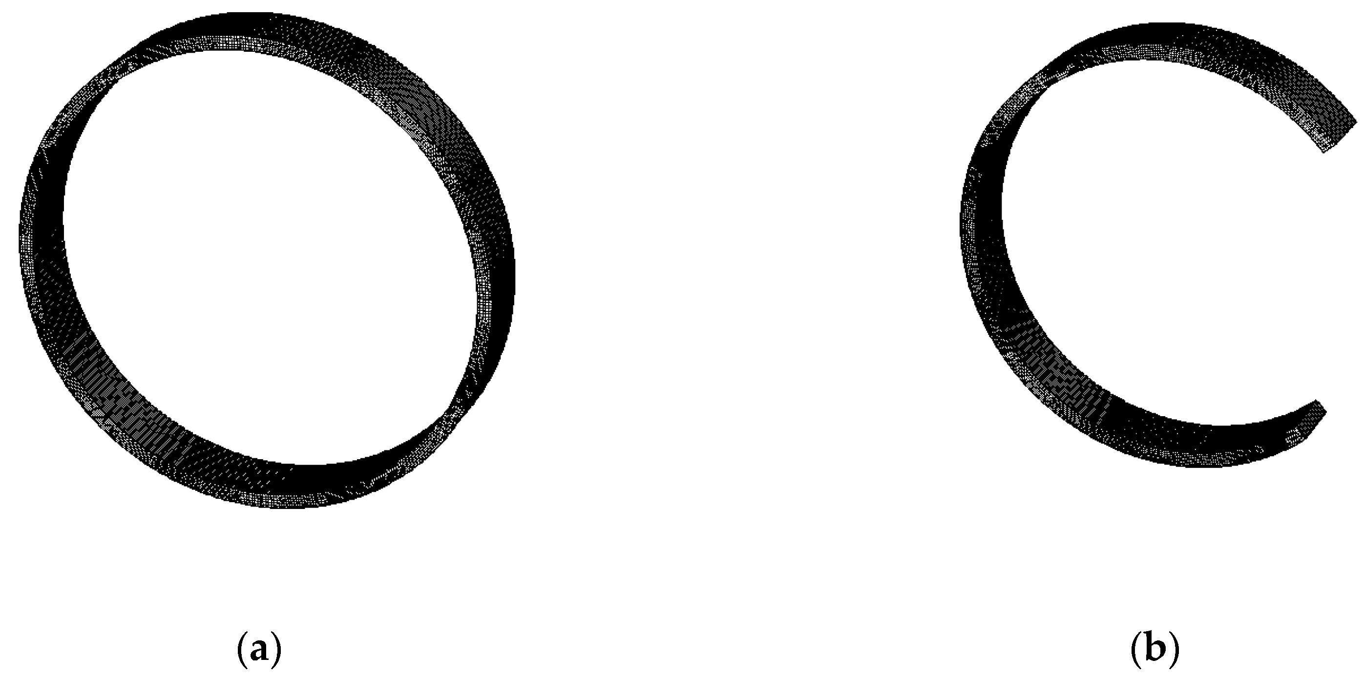
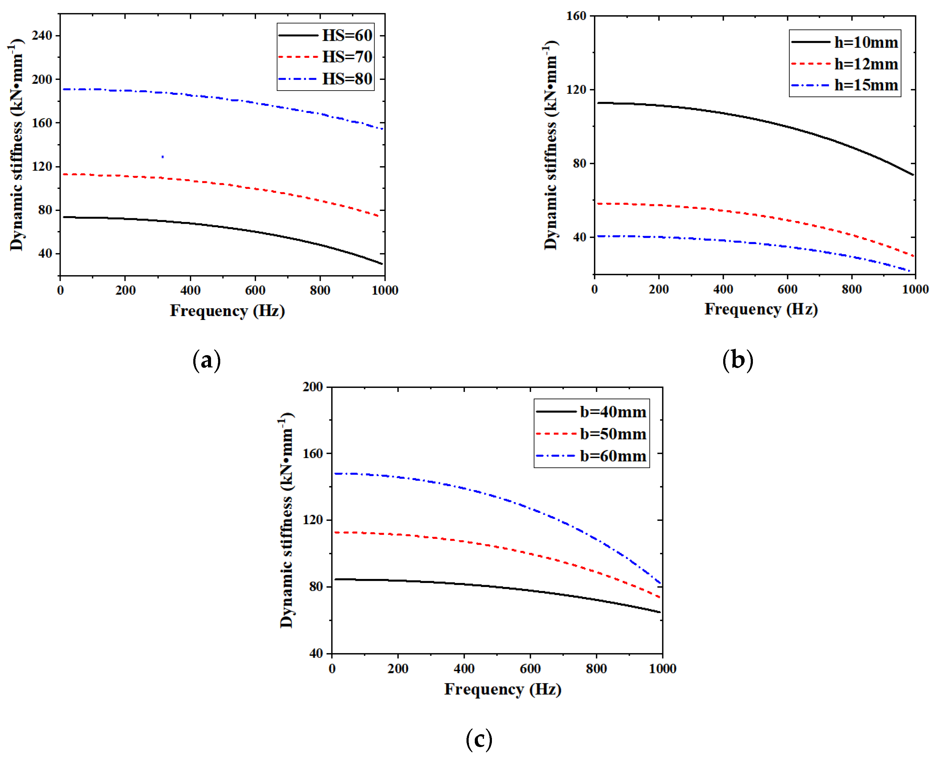
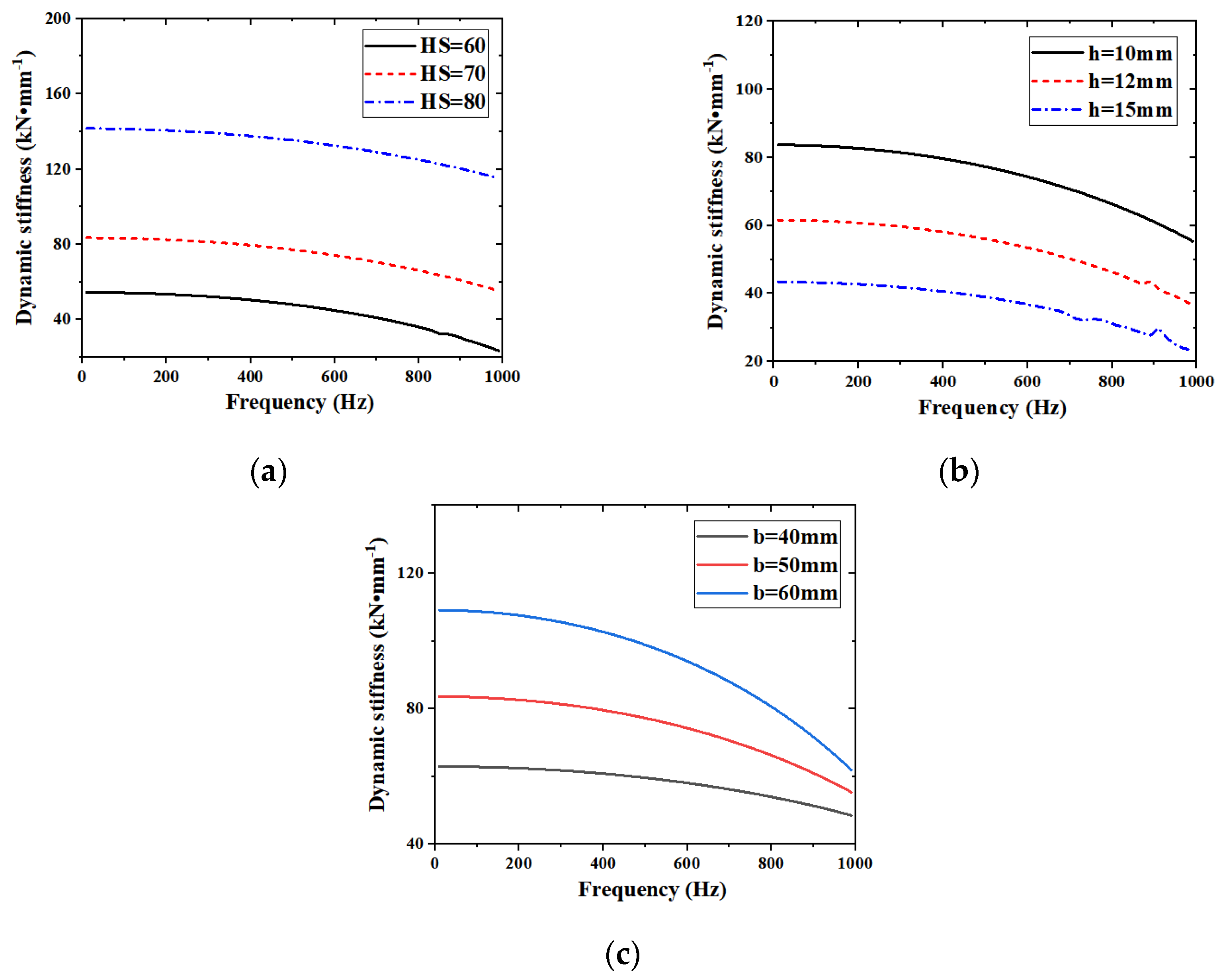
4.1. Dynamic Stiffness Analysis of the Rubber Ring Isolator
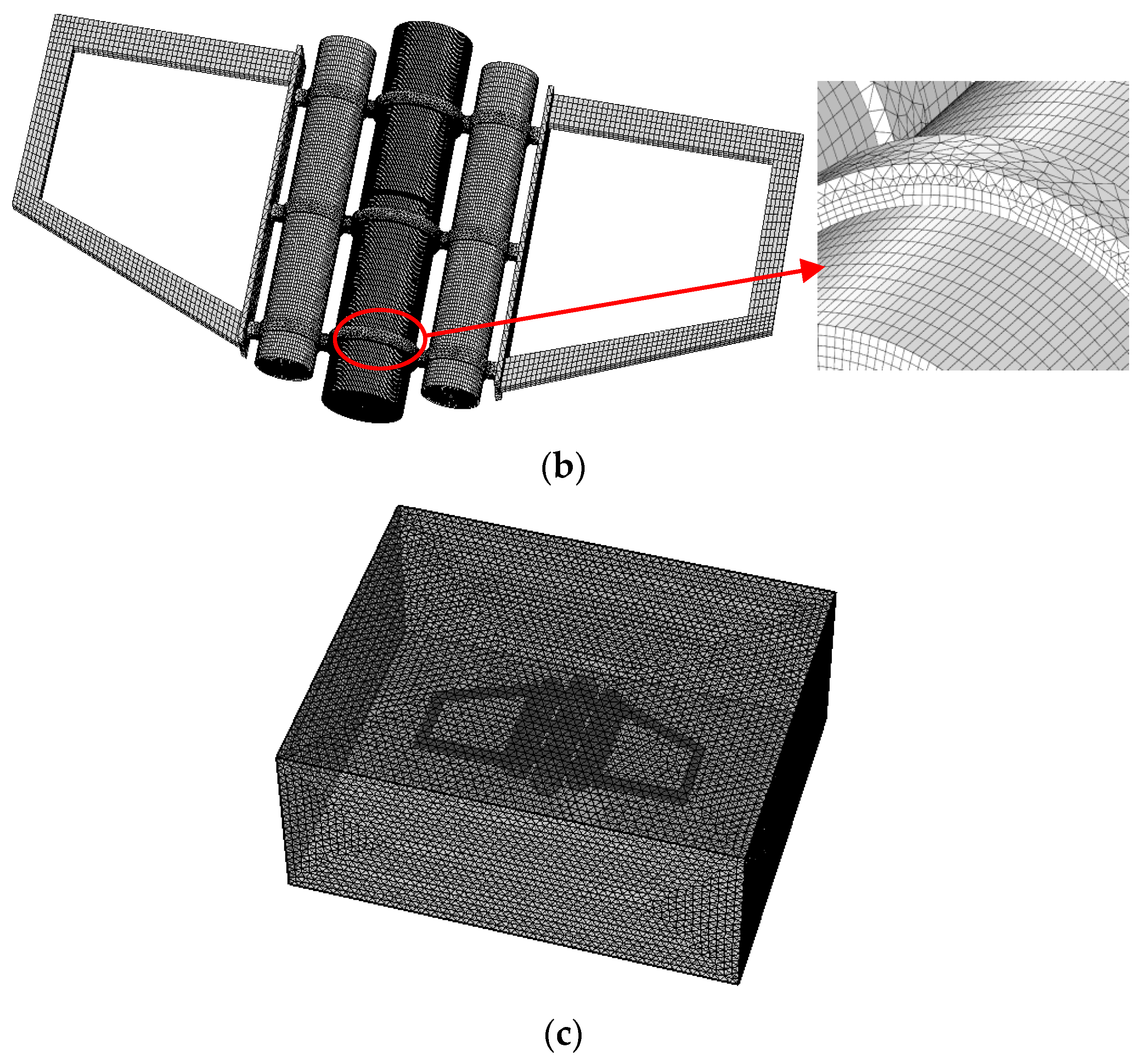
4.2. Coupled Vibro-Acoustic Finite Element Model
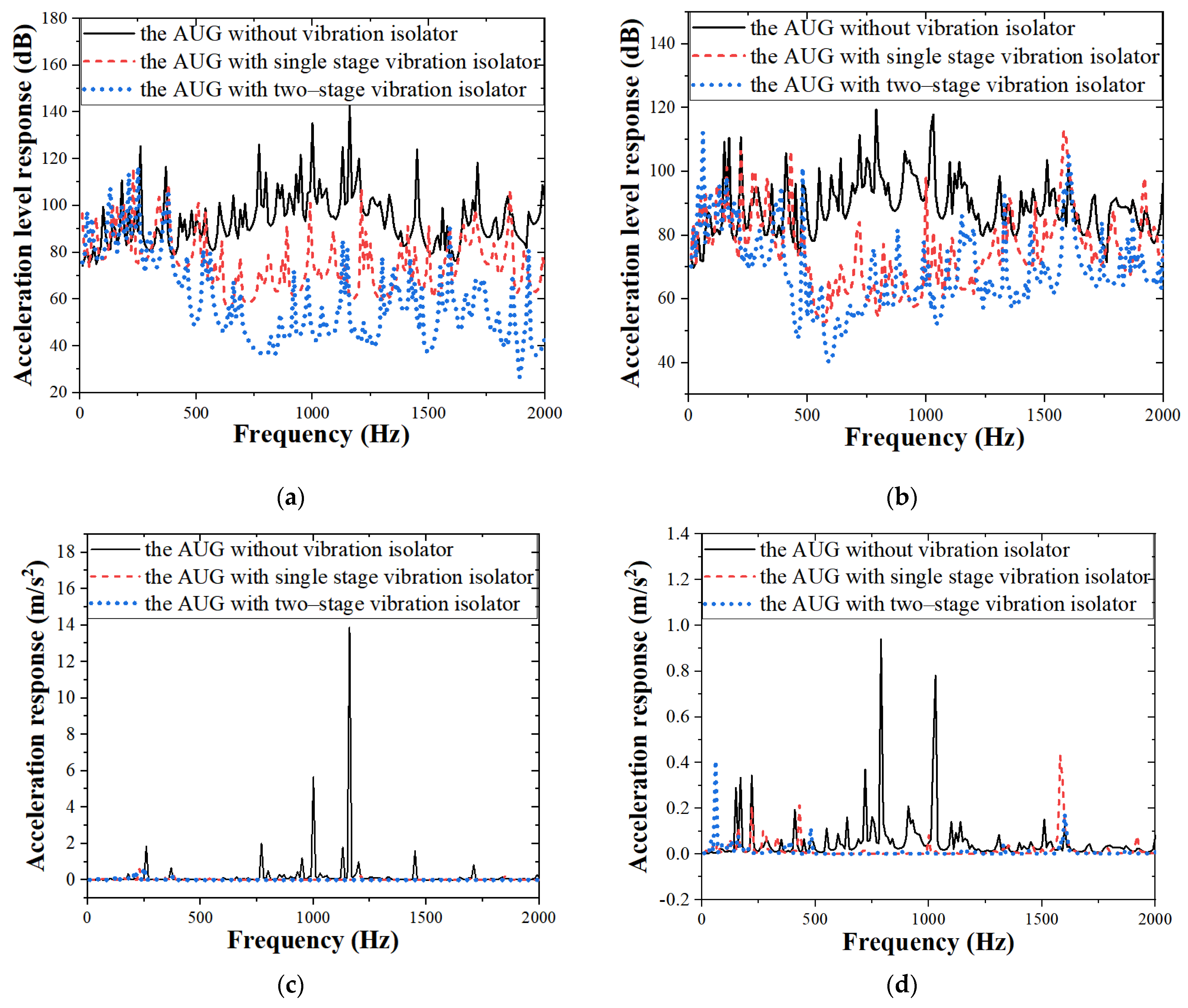
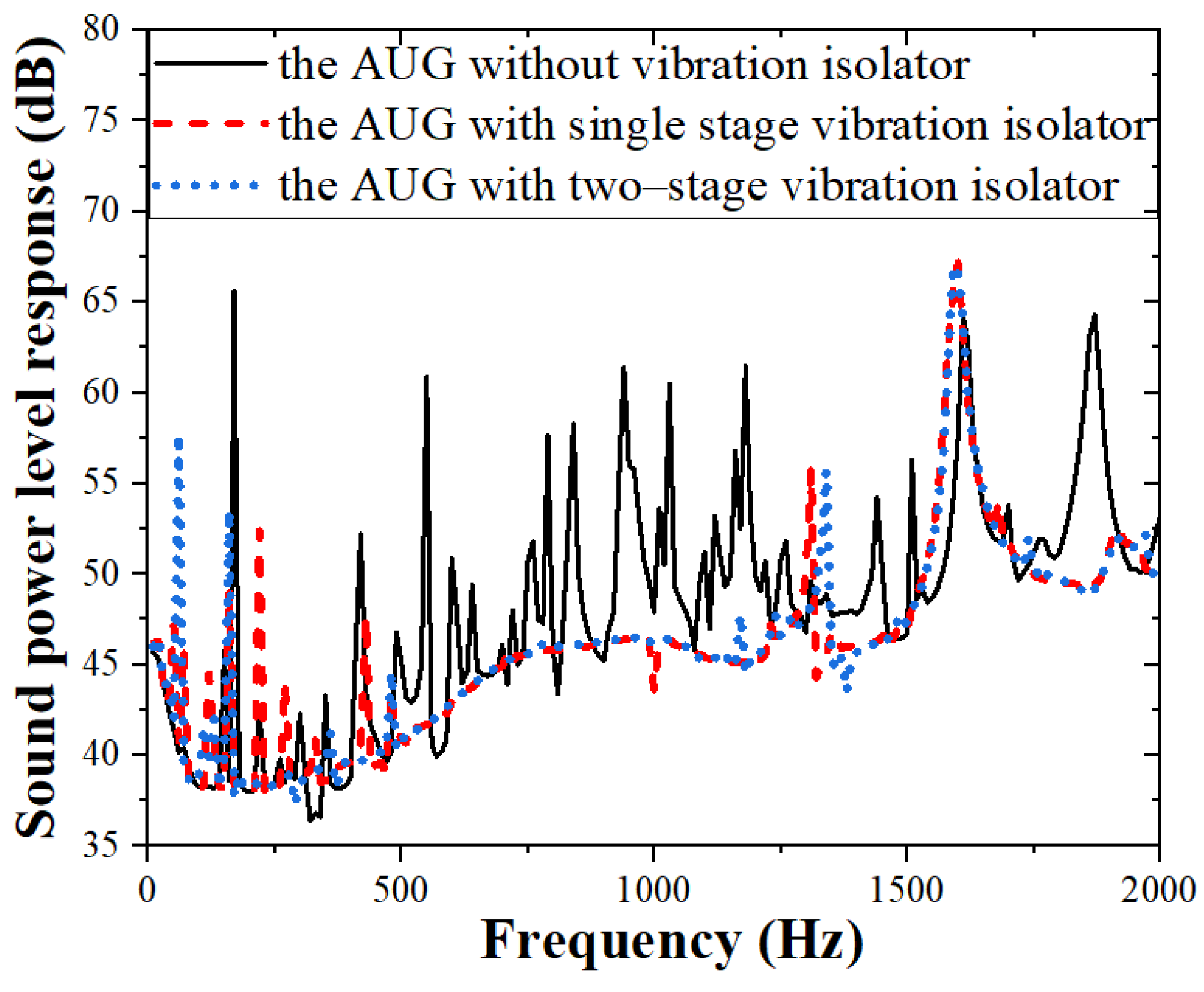
4.3. Vibration and Sound Responses of the Single- and Two-stage Vibration Isolation
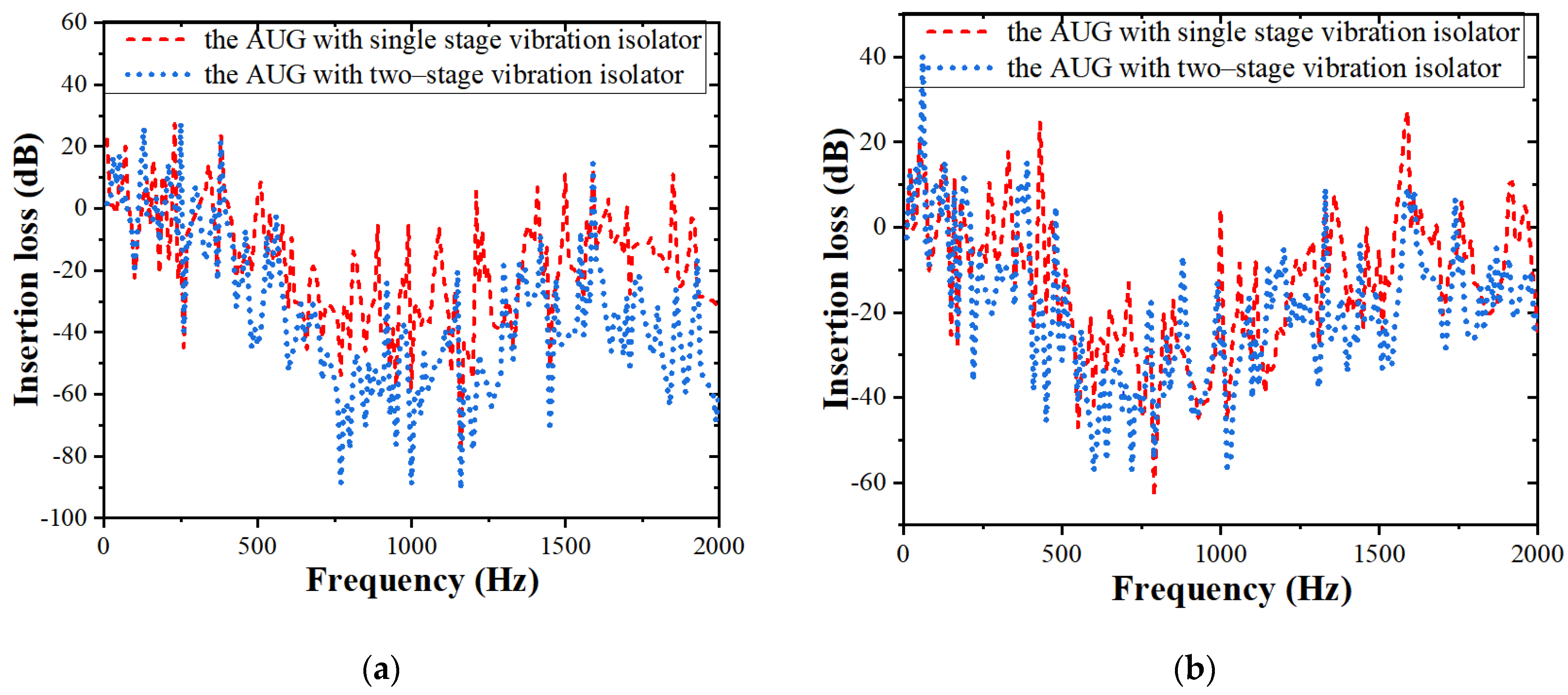
4.4. Insertion Loss of the Single- and Two-Stage Vibration Isolation
5. Conclusions
Author Contributions
Funding
Data Availability Statement
Conflicts of Interest
References
- Jenkins, S.A.; D’Spain, D. Autonomous underwater gliders. In Springer Handbook of Ocean Engineering, 1st ed.; Springer International Publishing: New York, NY, USA, 2016; Volume 9, pp. 301–322. [Google Scholar]
- Rudnick, D.L.; Davis, R.E.; Eriksen, C.C.; Fratantoni, D.M.; Perry, M.J. Underwater gliders for ocean research. Mar. Technol. Soc. J. 2004, 38, 73–84. [Google Scholar] [CrossRef]
- Ullah, B.; Ovinis, M.; Baharom, M.B.; Javaid, M.Y.; Izhar, S.S. Underwater gliders control strategies: A review. In Proceedings of the Control Conference, Kota Kinabalu, Malaysia, 3 June 2015. [Google Scholar]
- Javaid, M.Y.; Ovinis, M.; Nagarajan, T.; Hashim, F.B.M. Underwater gliders: A review. MATEC Web Conf. 2014, 13, 02020. [Google Scholar] [CrossRef]
- Rudnick, D.L. Ocean Research Enabled by Underwater Gliders. Annu. Rev. Mar. Sci. 2016, 8, 519–541. [Google Scholar] [CrossRef] [PubMed]
- Zhang, S.; Yu, J.; Zhang, A.; Zhang, F. Spiraling motion of underwater gliders: Modeling, analysis, and experimental results. Ocean Eng. 2013, 60, 1–13. [Google Scholar] [CrossRef]
- Fan, S.; Woolsey, C.A. Dynamics of underwater gliders in currents. Ocean Eng. 2014, 84, 249–258. [Google Scholar] [CrossRef]
- Wang, C.; Yuan, M. Research on the Ambient Noise Observation Technology Based on the Underwater Glider. Acoust. Aust. 2021, 49, 485–493. [Google Scholar] [CrossRef]
- Ferguson, B.G.; Lo, K.W.; Rodgers, J.D. Sensing the underwater acoustic environment with a single hydrophone onboard an undersea glider. In Proceedings of the Oceans’10 IEEE Sydney, Sydney, Australia, 24–27 May 2010; pp. 1–5. [Google Scholar]
- Liu, J.; Xu, Y.; Pan, G. A combined acoustic and dynamic model of a defective ball bearing. J. Sound Vib. 2021, 501, 116029. [Google Scholar] [CrossRef]
- Shi, Z.; Liu, J.; Li, H.; Zhang, Q.; Xiao, G. Dynamic simulation of a planet roller bearing considering the cage bridge crack. Eng. Fail. Anal. 2022, 131, 105849. [Google Scholar] [CrossRef]
- Liu, J.; Tang, C.; Pan, G. Dynamic modeling and simulation of a flexible-rotor ball bearing system. J. Vib. Control 2021. [Google Scholar] [CrossRef]
- Liu, J.; Tang, C.; Wu, H.; Xu, Z.; Wang, L. An analytical calculation method of the load distribution and stiffness of an angular contact ball bearing. Mech. Mach. Theory 2019, 142, 103597. [Google Scholar] [CrossRef]
- Liu, J.; Xu, Z. A simulation investigation of lubricating characteristics for a cylindrical roller bearing of a high-power gearbox. Tribol. Int. 2022, 167, 107373. [Google Scholar] [CrossRef]
- Song, D.L.; Zhang, C.L.; Nie, Y.L.; Zhu, Y.X.; Shi, Y.X. Research on the turbulence observation platform based on underwater glider. J. Ocean. Technol. 2015, 35, 1–5. [Google Scholar]
- Wang, C.; Han, M.; Sun, Q.; Lan, S. Noise measurement and optimization of underwater acoustic glider platform. J. Unmanned Undersea Syst. 2020, 28, 396–402. [Google Scholar]
- Liu, C.; Jing, X.; Daley, S.; Li, F. Recent advances in micro-vibration isolation. Mech. Syst. Signal Process. 2015, 56–57, 55–80. [Google Scholar] [CrossRef]
- Ibrahim, R.A. Recent advances in nonlinear passive vibration isolators. J. Sound Vib. 2008, 314, 371–452. [Google Scholar] [CrossRef]
- Ravindra, B.; Mallik, A.K. Performance of non-linear vibration isolators under harmonic excitation. J. Sound Vib. 1994, 170, 325–337. [Google Scholar] [CrossRef]
- Yilmaz, C.; Kikuchi, N. Analysis and design of passive low-pass filter-type vibration isolators considering stiffness and mass limitations. J. Sound Vib. 2006, 293, 171–195. [Google Scholar] [CrossRef]
- Kari, L. On the dynamic stiffness of preloaded vibration isolators in the audible frequency range: Modeling and experiments. J. Acoust. Soc. Am. 2003, 113, 1909–1921. [Google Scholar] [CrossRef]
- Majak, J.; Pohlak, M. Decomposition method for solving optimal material orientation problems. Compos. Struct. 2010, 92, 1839–1845. [Google Scholar] [CrossRef]
- Jazar, R.; Narimani, A.; Golnaraghi, M.; Swanson, D. Practical Frequency and Time Optimal Design of Passive Linear Vibration Isolation Mounts. Veh. Syst. Dyn. 2003, 39, 437–466. [Google Scholar] [CrossRef]
- Majak, J.; Pohlak, M.; Eerme, M.; Velsker, T. Design of car frontal protection system using neural networks and genetic algorithm. Mechanics 2012, 18, 453–460. [Google Scholar] [CrossRef] [Green Version]
- Song, Y.; Wen, J.; Yu, D.; Liu, Y.; Wen, X. Reduction of vibration and noise radiation of an underwater vehicle due to propeller forces using periodically layered isolators. J. Sound Vib. 2014, 333, 3031–3043. [Google Scholar] [CrossRef]
- Yang, Y.; Pan, G.; Yin, S.; Yuan, Y.; Huang, Q. Verification of vibration isolation effectiveness of the underwater vehicle power plant. J. Mar. Sci. Eng. 2021, 9, 382. [Google Scholar] [CrossRef]
- Liu, S.-Y.; Yu, X.; Zhu, S.-J. Study on the chaos anti-control technology in nonlinear vibration isolation system. J. Sound Vib. 2008, 310, 855–864. [Google Scholar] [CrossRef]
- Liu, N.; Li, C.; Yin, C.; Dong, X.; Hua, H. Application of a dynamic antiresonant vibration isolator to minimize the vibration transmission in underwater vehicles. J. Vib. Control 2018, 24, 3819–3829. [Google Scholar] [CrossRef]
- Yu, N.; Ouyang, H.; Zhang, J.; Ye, J.; Yan, Q.; Zheng, X. Performance analyses of passive vibration isolator with parallel connection of quasi-zero stiffness and inerter dampers. Appl. Sci. 2020, 10, 6894. [Google Scholar] [CrossRef]
- Yan, L.; Gong, X. Experimental study of vibration isolation characteristics of a geometric anti-spring isolator. Appl. Sci. 2017, 7, 711. [Google Scholar] [CrossRef] [Green Version]
- Zhang, J.; Richards, C.M. Parameter identification of analytical and experimental rubber isolators represented by Maxwell models. Mech. Syst. Signal Process. 2007, 21, 2814–2832. [Google Scholar] [CrossRef]
- Gil-Negrete, N.; Vinolas, J.; Kari, L. A simplified methodology to predict the dynamic stiffness of carbon-black filled rubber isolators using a finite element code. J. Sound Vib. 2006, 296, 757–776. [Google Scholar] [CrossRef]
- Jin, J.; Zhang, Z.; Xiong, X. Dynamic stiffness calculation method for rubber ring isolator. Torpedo Technol. 2012, 20, 125–128. [Google Scholar]
- Moore, S. Analytical modelling of single and two-stage vibration isolation systems. In Proceedings of the ACOUSTICS 2011, Gold Coast, Australia, 2–4 November 2011; p. 116. [Google Scholar]
- Li, J.; Zhang, Z.; Xu, H.; Feng, Z. Dynamic characteristics of the vibratory roller test-bed vibration isolation system: Simulation and experiment. J. Terramechanics 2014, 56, 139–156. [Google Scholar] [CrossRef]
- Wang, X.; Zhou, J.; Xu, D.; Ouyang, H.; Duan, Y. Force transmissibility of a two-stage vibration isolation system with quasi-zero stiffness. Nonlinear Dyn. 2016, 87, 633–646. [Google Scholar] [CrossRef]
- Lu, Z.; Yang, T.; Brennan, M.J.; Li, X.; Liu, Z. On the performance of a two-stage vibration isolation system which has geometrically nonlinear stiffness. J. Vib. Acoust. 2014, 136, 064501. [Google Scholar] [CrossRef]
- Pan, J.; Hansen, C. Total power flow from a vibrating rigid body to a thin panel through multiple elastic mounts. J. Acoust. Soc. Am. 1992, 92, 895–907. [Google Scholar] [CrossRef]
- Xie, S.; Wing, S.; Chan, H.L.W.; Choy, P.K.; Liu, P.C.K. Analysis of vibration power flow from a vibrating machinery to a floating elastic panel. Mech. Syst. Signal Process. 2007, 21, 389–404. [Google Scholar] [CrossRef]
- Ashrafiuon, H.; Nataraj, C. Dynamic Analysis of Engine-Mount Systems. J. Vib. Acoust. 1992, 114, 79–83. [Google Scholar] [CrossRef]
- Puri, R.S.; Morrey, D.; Bell, A.J.; Durodola, J.; Rudnyi, E.B.; Korvink, J. Reduced order fully coupled structural–acoustic analysis via implicit moment matching. Appl. Math. Model. 2009, 33, 4097–4119. [Google Scholar] [CrossRef]
- Junge, M.; Brunner, D.; Gaul, L. Solution of the FE-BE coupled Eigenvalue problem for immersed ship-like structures. Int. J. Numer. Meth. Eng. 2011, 87, 664–676. [Google Scholar] [CrossRef]
- Peters, H.; Kinns, R.; Kessissoglou, N. Effects of apparent mass on the radiated sound power from fluid-loaded structures. Ocean Eng. 2015, 105, 83–91. [Google Scholar] [CrossRef]
- Peters, H.; Kessissoglou, N.; Marburg, S. Modal decomposition of exterior acoustic-structure interaction problems with model order reduction. J. Acoust. Soc. Am. 2014, 135, 2706–2717. [Google Scholar] [CrossRef]
- Frolov, K.V.; Furman, F.A.; Rivin, E.I. Applied Theory of Vibration Isolation Systems; Hemisphere Pub. Corp.: New York, NY, USA, 1990. [Google Scholar]


| Material Parameters | Material Types | Density | Young’s Modulus | Poisson’s Ratio |
|---|---|---|---|---|
| AUG structure | Aluminum | 2780 kg/m3 | 7.2 × 10¹⁰ Pa | 0.3 |
| Isolator | Rubber | 1100 kg/m3 | 1 × 10⁷ Pa | 0.49 |
Publisher’s Note: MDPI stays neutral with regard to jurisdictional claims in published maps and institutional affiliations. |
© 2022 by the authors. Licensee MDPI, Basel, Switzerland. This article is an open access article distributed under the terms and conditions of the Creative Commons Attribution (CC BY) license (https://creativecommons.org/licenses/by/4.0/).
Share and Cite
Liu, Y.; Liu, J.; Pan, G.; Huang, Q.; Guo, L. Dynamic Analysis of an Autonomous Underwater Glider with Single- and Two-Stage Vibration Isolators. J. Mar. Sci. Eng. 2022, 10, 162. https://doi.org/10.3390/jmse10020162
Liu Y, Liu J, Pan G, Huang Q, Guo L. Dynamic Analysis of an Autonomous Underwater Glider with Single- and Two-Stage Vibration Isolators. Journal of Marine Science and Engineering. 2022; 10(2):162. https://doi.org/10.3390/jmse10020162
Chicago/Turabian StyleLiu, Yujun, Jing Liu, Guang Pan, Qiaogao Huang, and Liming Guo. 2022. "Dynamic Analysis of an Autonomous Underwater Glider with Single- and Two-Stage Vibration Isolators" Journal of Marine Science and Engineering 10, no. 2: 162. https://doi.org/10.3390/jmse10020162