Assessment of Excessive Acceleration of the IMO Second Generation Intact Stability Criteria for the Tanker


Abstract
:1. Introduction
- (1)
- The pure loss of stability drastically reduces the stability of the vessel when the midpoint of the hull and the wave crest are same.
- (2)
- The parametric roll is a resonance that happens if the incident wave frequency on the ship is twice of the resonance roll frequency.
- (3)
- When a ship’s engine breaks down, the phenomenon that occurs due to the roll occurring when waves enter from the side of the hull is called the dead ship condition.
- (4)
- The surf-riding is formed when a vessel goes in the following wave, and the ship’s stability becomes weak as the vessel ride waves in a situation where the wave speed and the ship speed are nearly the same. In the broaching, the ship loses directional stability while the surf-riding continues, resulting in a loss of stability in a maneuverable state [3,4].
- (5)
- The phenomenon of cargo falling overboard due to acceleration caused by the restoring force caused by GM, metacentric height is called excessive acceleration.
- (a)
- When a ship is rolling, the objects in higher locations travel longer distances. A period of roll motions is the same for all the location onboard the ship [5].
- (b)
- To cover longer distance during the same time, the linear velocity must be larger. As the velocity changes its direction every half a period, larger linear velocity leads to larger linear accelerations. Large linear acceleration means lager inertial force [5].
- (c)
- Large accelerations are mostly caused by roll motions so they have predominantly lateral direction [5].
- (d)
- If the GM value is large, the period of roll motion is smaller. Thus, for the same roll amplitude the changes of linear velocity occur faster, so accelerations are larger [5].
- (a)
- (b)
- (c)
- [10]: Description of excessive acceleration Lv2 criteria
2. Theory
2.1. Lv1 Vulnerability Criterion
2.2. Lv2 Vulnerability Criterion
3. Lv1 Vulnerability Criterion Assessment of Excessive Acceleration Mode
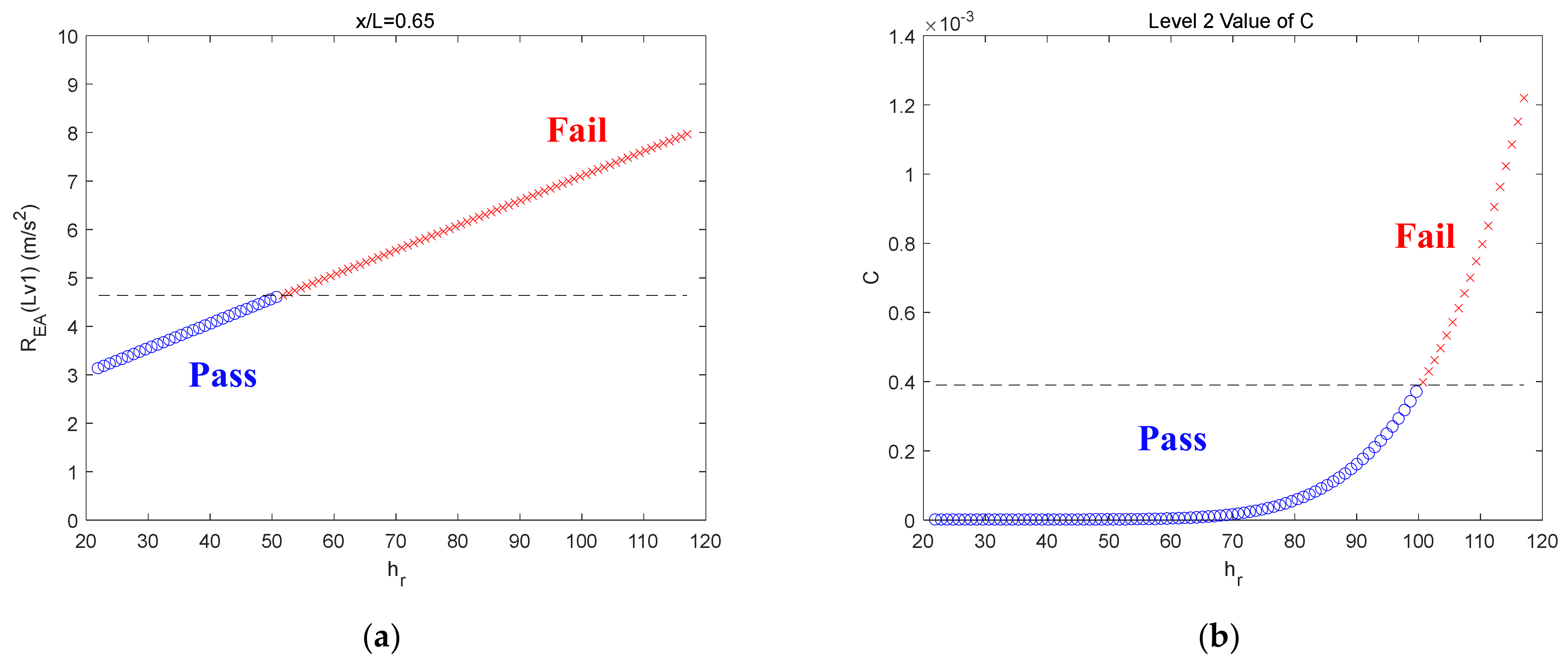
4. Lv2 Vulnerability Criterion Assessment of Excessive Acceleration Mode
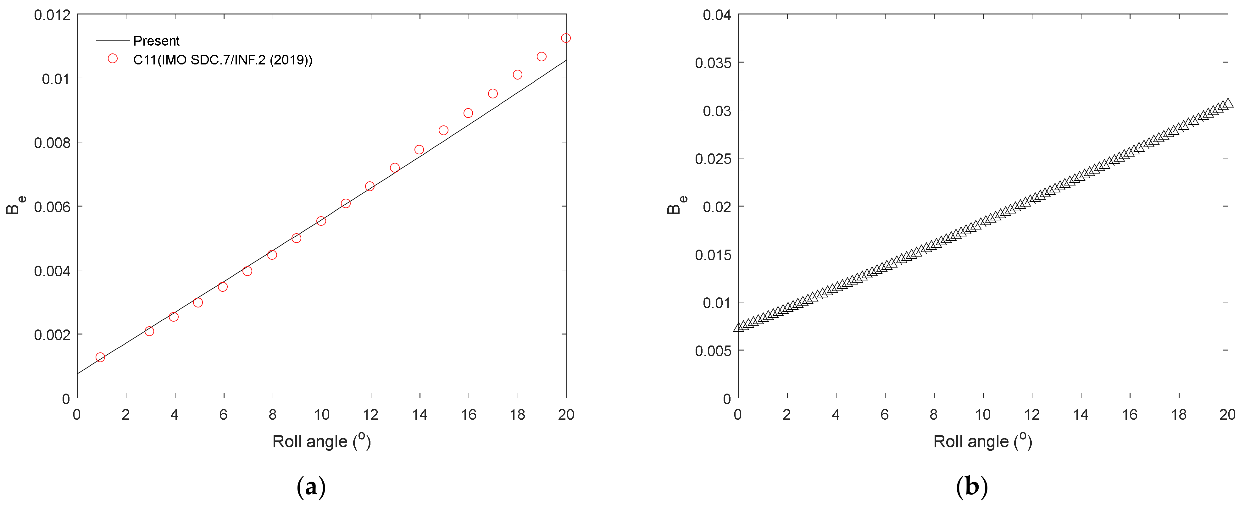
- BF: Frictional component
- BE: Eddy component
- BL: Lift component
- BBK: Bilge keel component
- BW: Wave component
- cf: Frictional coefficient
- rf: Average radius from the axis of rolling
- sf: Wetted surface area
- φa: Roll amplitude
- Tφ: Roll period
- ν: The coefficient of dynamic viscosity
- OG = KG − d
5. Conclusions
Author Contributions
Funding
Acknowledgments
Conflicts of Interest
References
- IMO SDC 4/WP.4 Annex 1Draft Guidelines of Direct Stability Assessment Procedures for Use with the Second Generation Intact Stability Criteria, International Maritime Organization: London, UK, 2017.
- IMO SDC 5/INF 4 Add.1Draft Guidelines of Direct Stability Assessment Procedures for Use with the Second Generation Intact Stability Criteria, International Maritime Organization: London, UK, 2017.
- Belenky, V.; Bassler, C.C.; Spyrou, K.J. Development of Second Generation Intact Stability Criteria; Hydromechanics Department Report, Naval Surface Warfare Center Carderock Division-50-TR-2011/065; Naval Surface Warfare Center: West Bethesda, MD, USA, 2011. [Google Scholar]
- Spyrou, K.J. The Nonlinear Dynamics of Ships in Broaching. Marie Curie Fellowsh. Ann. 2001, 1, 1–13. [Google Scholar]
- IMO SDC 7/INF.2Draft Guidelines of Direct Stability Assessment Procedures for Use with the Second Generation Intact Stability Criteria, International Maritime Organization: London, UK, 2019.
- IMO SDC 2/WP.4Draft Guidelines of Direct Stability Assessment Procedures for Use with the Second Generation Intact Stability Criteria, International Maritime Organization: London, UK, 2015.
- IMO SDC 3/6/6Draft Guidelines of Direct Stability Assessment Procedures for Use with the Second Generation Intact Stability Criteria, International Maritime Organization: London, UK, 2015.
- IMO SDC 3/INF.10Draft Guidelines of Direct Stability Assessment Procedures for Use with the Second Generation Intact Stability Criteria, International Maritime Organization: London, UK, 2015.
- IMO SDC 3/WP.5Draft Guidelines of Direct Stability Assessment Procedures for Use with the Second Generation Intact Stability Criteria, International Maritime Organization: London, UK, 2016.
- IMO SDC 4/5/4Draft Guidelines of Direct Stability Assessment Procedures for Use with the Second Generation Intact Stability Criteria, International Maritime Organization: London, UK, 2016.
- IMO SDC 6/WP.6Draft Guidelines of Direct Stability Assessment Procedures for Use with the Second Generation Intact Stability Criteria, International Maritime Organization: London, UK, 2019.
- IMO SDC 7/WP.6Draft Guidelines of Direct Stability Assessment Procedures for Use with the Second Generation Intact Stability Criteria, International Maritime Organization: London, UK, 2020.
- Zheng, Y.H.; You, Y.G.; Shen, Y.M. On the radiation and diffraction of water waves by a rectangular buoy. Ocean Eng. 2004, 31, 1063–1082. [Google Scholar] [CrossRef]
- Lee, C.; Kang, C. Hull Form Study for 21C 13 K Chemical Tanker; KRISO Model Test Report. No. BSIO2610-04601E; KRISO: Daejeon, Korea, 2004. [Google Scholar]
- Kawahara, Y.; Maekawa, K.; Ikeda, Y. A simple prediction formula of roll damping of conventional cargo ships on the basis of Ikeda’s method and its limitation. J. Shipp. Ocean. Eng. 2012, 2, 201. [Google Scholar]
- Shin, D.M.; Moon, B.Y.; Chung, J. Application of surf-riding and broaching mode based on IMO second-generation intact stability criteria for previous ships. Int. J. Nav. Archit. Ocean. Eng. 2021, 13, 545–553. [Google Scholar] [CrossRef]
- Shin, D.M.; Chung, J. Application of dead ship condition based on IMO second-generation intact stability criteria for 13 K oil chemical tanker. Ocean Eng. 2021, 238, 109776. [Google Scholar] [CrossRef]


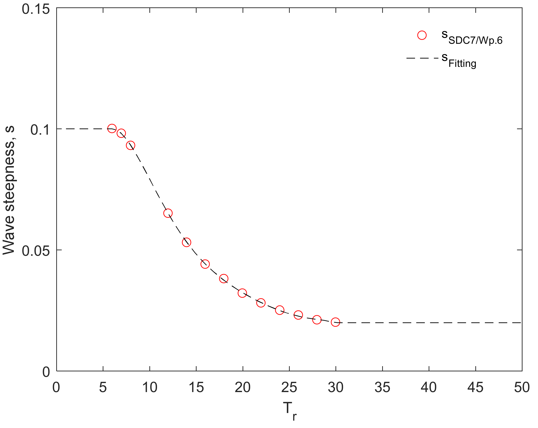
| Natural Roll Period Tr (s) | Wave Steepness s = H/λ |
|---|---|
| <6 | 0.1 |
| 6 | 0.1 |
| 7 | 0.098 |
| 8 | 0.093 |
| 12 | 0.065 |
| 14 | 0.053 |
| 16 | 0.044 |
| 18 | 0.038 |
| 20 | 0.032 |
| 22 | 0.028 |
| 24 | 0.025 |
| 26 | 0.023 |
| 28 | 0.021 |
| 30 | 0.02 |
| >30 | 0.02 |
| w0 | w1 | w2 | w3 | w4 | w5 | w6 |
|---|---|---|---|---|---|---|
| −0.07668 | 0.081022 | −0.01338 | 0.001011 |
| Number of Occurrences: 100,000/Tz (s) = Average Zero Up-Crossing Wave Period | ||||||||||||||||
|---|---|---|---|---|---|---|---|---|---|---|---|---|---|---|---|---|
| Tz → | 3.5 | 4.5 | 5.5 | 6.5 | 7.5 | 8.5 | 9.5 | 10.5 | 11.5 | 12.5 | 13.5 | 14.5 | 15.5 | 16.5 | 17.5 | 18.5 |
| Hs ↓ | ||||||||||||||||
| 0.5 | 1.3 | 133.7 | 865.6 | 1186 | 634.2 | 186.3 | 36.9 | 5.6 | 0.7 | 0.1 | 0 | 0 | 0 | 0 | 0 | 0 |
| 1.5 | 0 | 29.3 | 986 | 4976 | 7738 | 5569.7 | 2375.7 | 703.5 | 160.7 | 30.5 | 5.1 | 0.8 | 0.1 | 0 | 0 | 0 |
| 2.5 | 0 | 2.2 | 197.5 | 2158.8 | 6230 | 7449.5 | 4860.4 | 2066 | 644.5 | 160.2 | 33.7 | 6.3 | 1.1 | 0.2 | 0 | 0 |
| 3.5 | 0 | 0.2 | 34.9 | 695.5 | 3226.5 | 5675 | 5099.1 | 2838 | 1114.1 | 337.7 | 84.3 | 18.2 | 3.5 | 0.6 | 0.1 | 0 |
| 4.5 | 0 | 0 | 6 | 196.1 | 1354.3 | 3288.5 | 3857.5 | 2685.5 | 1275.2 | 455.1 | 130.9 | 31.9 | 6.9 | 1.3 | 0.2 | 0 |
| 5.5 | 0 | 0 | 1 | 51 | 498.4 | 1602.9 | 2372.7 | 2008.3 | 1126 | 463.6 | 150.9 | 41 | 9.7 | 2.1 | 0.4 | 0.1 |
| 6.5 | 0 | 0 | 0.2 | 12.6 | 167 | 690.3 | 1257.9 | 1268.6 | 825.9 | 386.8 | 140.8 | 42.2 | 10.9 | 2.5 | 0.5 | 0.1 |
| 7.5 | 0 | 0 | 0 | 3 | 52.1 | 270.1 | 594.4 | 703.2 | 524.9 | 276.7 | 111.7 | 36.7 | 10.2 | 2.5 | 0.6 | 0.1 |
| 8.5 | 0 | 0 | 0 | 0.7 | 15.4 | 97.9 | 255.9 | 350.6 | 296.9 | 174.6 | 77.6 | 27.7 | 8.4 | 2.2 | 0.5 | 0.1 |
| 9.5 | 0 | 0 | 0 | 0.2 | 4.3 | 33.2 | 101.9 | 159.9 | 152.2 | 99.2 | 48.3 | 18.7 | 6.1 | 1.7 | 0.4 | 0.1 |
| 10.5 | 0 | 0 | 0 | 0 | 1.2 | 10.7 | 37.9 | 67.5 | 71.7 | 51.5 | 27.3 | 11.4 | 4 | 1.2 | 0.3 | 0.1 |
| 11.5 | 0 | 0 | 0 | 0 | 0.3 | 3.3 | 13.3 | 26.6 | 31.4 | 24.7 | 14.2 | 6.4 | 2.4 | 0.7 | 0.2 | 0.1 |
| 12.5 | 0 | 0 | 0 | 0 | 0.1 | 1 | 4.4 | 9.9 | 12.8 | 11 | 6.8 | 3.3 | 1.3 | 0.4 | 0.1 | 0 |
| 13.5 | 0 | 0 | 0 | 0 | 0 | 0.3 | 1.4 | 3.5 | 5 | 4.6 | 3.1 | 1.6 | 0.7 | 0.2 | 0.1 | 0 |
| 14.5 | 0 | 0 | 0 | 0 | 0 | 0.1 | 0.4 | 1.2 | 1.8 | 1.8 | 1.3 | 0.7 | 0.3 | 0.1 | 0 | 0 |
| 15.5 | 0 | 0 | 0 | 0 | 0 | 0 | 0.1 | 0.4 | 0.6 | 0.7 | 0.5 | 0.3 | 0.1 | 0.1 | 0 | 0 |
| 16.5 | 0 | 0 | 0 | 0 | 0 | 0 | 0 | 0.1 | 0.2 | 0.2 | 0.2 | 0.1 | 0.1 | 0 | 0 | 0 |
| Parameters | 13 K Oil Chemical Oanker |
|---|---|
| Length L (m) | 120.4 |
| Breadth B (m) | 20.4 |
| Draft d (m) | 8.7 |
| Block coefficient CB | 0.8 |
| Midship coefficient CM | 0.995 |
| Prismatic coefficient Cp (= CB/CM) | 0.8 |
| Displacement Δ (ton) | 17,457.3 |
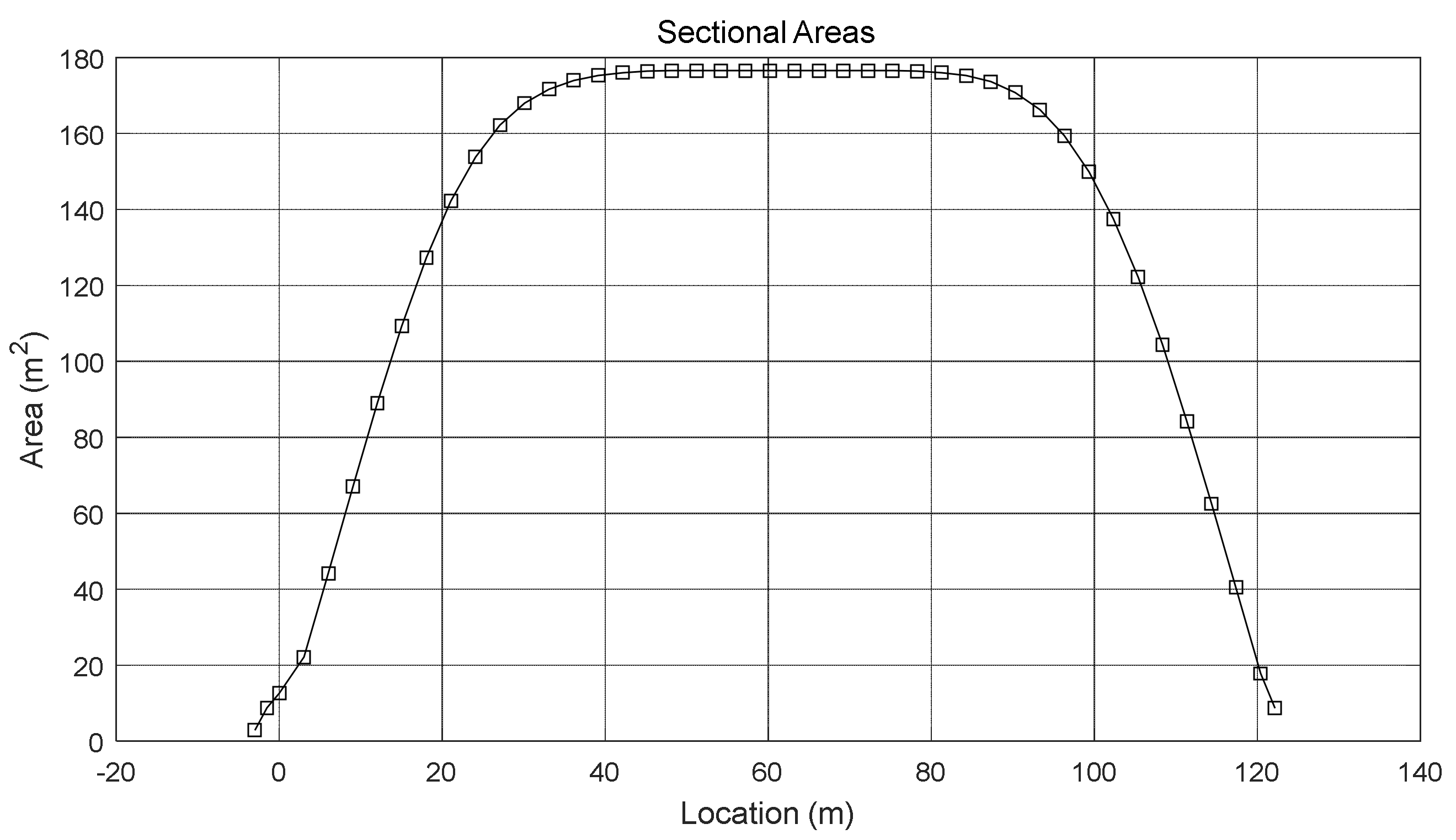
| Midship section area (m2) | 176.5 |
| Length of waterline (m) | 123.76 |
| Bilge keel area (m2) | 33.1 |
| GM (m) | 1.472 |
| KG (m) | 7.304 |
| Location (m) | Area (m2) | Location (m) | Area (m2) | Location (m) | Area (m2) | Location (m) | Area (m2) | Location (m) | Area (m2) |
|---|---|---|---|---|---|---|---|---|---|
| −3.000 | 2.9 | 21.070 | 142.2 | 48.160 | 176.5 | 75.250 | 176.5 | 102.340 | 137.5 |
| −1.500 | 8.8 | 24.080 | 153.8 | 51.170 | 176.5 | 78.260 | 176.4 | 105.350 | 122.2 |
| 0.000 | 12.6 | 27.090 | 162.2 | 54.180 | 176.5 | 81.270 | 176.0 | 108.360 | 104.4 |
| 0.3010 | 22.1 | 30.100 | 168.0 | 57.190 | 176.5 | 84.280 | 175.2 | 111.370 | 84.2 |
| 6.020 | 44.2 | 33.110 | 171.7 | 60.200 | 176.5 | 87.290 | 173.6 | 114.380 | 62.5 |
| 9.030 | 67.1 | 36.120 | 174.0 | 63.210 | 176.5 | 90.300 | 170.8 | 117.390 | 40.5 |
| 12.040 | 89.0 | 39.130 | 175.3 | 66.220 | 176.5 | 93.310 | 166.2 | 120.400 | 17.8 |
| 15.050 | 109.3 | 42.140 | 176.0 | 69.230 | 176.5 | 96.320 | 159.4 | 122.150 | 8.7 |
| 18.060 | 127.3 | 45.150 | 176.4 | 72.240 | 176.5 | 99.330 | 149.9 |
Publisher’s Note: MDPI stays neutral with regard to jurisdictional claims in published maps and institutional affiliations. |
© 2022 by the authors. Licensee MDPI, Basel, Switzerland. This article is an open access article distributed under the terms and conditions of the Creative Commons Attribution (CC BY) license (https://creativecommons.org/licenses/by/4.0/).
Share and Cite
Shin, D.-M.; Moon, B.-Y. Assessment of Excessive Acceleration of the IMO Second Generation Intact Stability Criteria for the Tanker. J. Mar. Sci. Eng. 2022, 10, 229. https://doi.org/10.3390/jmse10020229
Shin D-M, Moon B-Y. Assessment of Excessive Acceleration of the IMO Second Generation Intact Stability Criteria for the Tanker. Journal of Marine Science and Engineering. 2022; 10(2):229. https://doi.org/10.3390/jmse10020229
Chicago/Turabian StyleShin, Dong-Min, and Byung-Young Moon. 2022. "Assessment of Excessive Acceleration of the IMO Second Generation Intact Stability Criteria for the Tanker" Journal of Marine Science and Engineering 10, no. 2: 229. https://doi.org/10.3390/jmse10020229
APA StyleShin, D.-M., & Moon, B.-Y. (2022). Assessment of Excessive Acceleration of the IMO Second Generation Intact Stability Criteria for the Tanker. Journal of Marine Science and Engineering, 10(2), 229. https://doi.org/10.3390/jmse10020229