Article

Numerical and Experimental Study of Hydrodynamic Response for a Novel Buoyancy-Distributed Floating Foundation Based on the Potential Theory

School of Mechanical Engineering and Automation, Harbin Institute of Technology (Shenzhen), Shenzhen 518055, China
*
Author to whom correspondence should be addressed.
J. Mar. Sci. Eng. 2022, 10(2), 292; https://doi.org/10.3390/jmse10020292
Submission received: 7 January 2022 / Revised: 13 February 2022 / Accepted: 17 February 2022 / Published: 19 February 2022
(This article belongs to the Section Ocean Engineering)

Abstract

:
Floating foundations play a vital role in exploring offshore energy. After analyzing various floating foundation concepts, this paper presents a novel buoyancy-distributed floating foundation (BDFF) inspired by the decentralized concept. The calculations of a floating system based on the BDFF design were performed for a series of wave conditions. The potential theory and the boundary element method (BEM) were used in the numerical progress. A broader view was focused on the impacts of wave frequency and wave directions on the system. The proposed floating system was further validated through wave tests in a wave tank, showing that the potential theory can satisfactorily predict the RAOs in regular waves. Moreover, numerical results and experimental results were compared with a conventional SPAR. Finally, the coupling relationship between six degrees of freedom was described.

1. Introduction

Currently, renewable energy is the most effective way to achieve “carbon peak” and “carbon neutralization” for a low-carbon future. Floating foundations are major supporting platforms for exploring offshore renewable energy, which is still in its infancy. Europe has launched the Wind Power Initiative to provide technical and market support for harnessing deep-water winds as early as 2010 [1]. In addition, the governments of France, Portugal, and Norway have provided financial support for deep-water wind projects. Japan and the USA are following the pace of Europe to study deep floating wind closely. After the Fukushima nuclear power plant accident in 2011, Japan switched from nuclear energy to offshore wind energy for a long-term layout. Japan has carried out experimental research on different types of full-scale offshore wind farms with a total installed capacity of 12 MW. The demonstration wind farm worldwide has strongly promoted its commercialization process and competed with the fixed foundation in cost.
A floating offshore platform can majorly be broken down into several systems: A mooring system, a floating foundation (sometimes containing a ballast system), and a superstructure (e.g., a wind turbine). The floating foundation plays a crucial role in developing offshore wind farms. There are four types of floating foundation: The barge type, the SPAR type, the TLP type, and the semi-submersible type. The barge has a large cut-water plane whose hydrodynamic performance is similar to semi-submersible. The SPAR is stabilized by ballasts with low COG while the TLP is balanced by tensioned mooring cables with elastic characteristics. The SPAR with catenary mooring lines and the TLP with taut mooring lines are both semi-submersible floating foundations in a broad sense [2]. There exist various conceptions among the four types. BlueWater-TLP, Iberdrola TLPWIND, and PelaStar are comprised of a central column floater and three, four, and five cantilever floaters, respectively [3,4,5]. In order to remove the transportation cost of temporary ballasts and reduce the damage to the seabed, a lowerable steel concrete anchor and gravity anchor was incorporated like Diwets [6] and GICON®SOF [7]. Similarly, a selfinstalling floating wind turbine was researched by Iv-Groep company; its anchors can be raised and lowered through tension mooring lines to meet the water depth requirements [8]. The TLP can be installed in a wide water depth range, while the SPAR can only be applied to deep-water areas. The structural design of SPAR is not convenient for manufacturing, transportation, and installation. The Hywind developed by Equinor company (formerly Statoil) has been put into use in the offshore wind farm [9]. The SWAY proposed by Norway’s Inocean company adopts a single rigid mooring pipe instead of catenary mooring, which significantly reduces the mooring cost [10].
Compared with the TLP and the SPAR, the barge is simple in structure, but it is prone to extreme pitch angles under extreme wave load [11]. BW Ideol has manufactured a floating barge FLOATGEN with a central damping pool (also called moon pool) and installed prototypes in France and Japan, respectively [12]. Among all the floating conceptions, the semi-submersible is the most studied due to the structural diversity. The Dutch Trifloater [13] and OC4-DeepCWind [14] consist of three column floaters located at the vertices of an equilateral triangle at whose center an HVWT stands while the Nautilus [15] comprises four-column floaters. Furthermore, the WindFloat [16], W2power [17], and WindSea Floater [18] are equipped with one, two, and three HVWTs on one, two, and three floaters of the triangle, respectively, instead of the center of the triangle, resulting in asymmetry in structure and quality, which was balanced by an active ballast system. To avoid fatigue fracture under long-term load, the girders connecting floaters can be replaced by bottom rectangular ballast tanks like Shimpuu [2], Tri-Floater [19], and OO Star [20]. The structural stiffness and stability can be improved by increasing the connecting rods or inclining the floaters, such as the TwinWind [21] and WindFlo [22]. The floating wind turbines mentioned above are listed in Table 1.
This paper introduced a novel concept of the buoyancy-distributed floating foundation. A BDFF is a foundation whose buoyancy is provided by many identical floaters connected by girders or themselves in specific patterns. It deals with a crucial challenge: When one of the floaters fails, it does not imply the entire foundation fails. Meanwhile, the cut-water plane area can be effectively decreased by increasing the number of floaters. Some existing designs can be roughly regarded as a BDFF. The SATH with a single-point mooring designed by the Saitec company in Spain is a somewhat simplified BDFF with two identical horizontal concrete floaters connected to the heave plate at the bottom through a frame [23]. Moreover, the SBM-offshore conception with three tension legs consists of four identical floaters: A central floater and the other three are side floaters. The floaters below the waterline and the HVWT above the waterline are connected by girders, on which the hydrodynamic effect of wave load on the BDFF is not evident due to the small cut-water plane area. Moreover, up to six identical floaters with catenary mooring cables are based on the semi-submersible OC4-Deepwind model as studied by Liu et al. on the seakeeping performance of the structure when the total mass remains unchanged. The results show that the dynamics of the surge, heave, and pitch of the BDFF can be improved when the cut-water plane area decreases, i.e., the number of offset floats increases from 3 to 6 [24]. Similarly, the GICON company designed a TLP-based BDFF named GICON-TLP, the total buoyancy of which comes from eight modular cylindrical floaters. In order to achieve stability during transportation, installation, and service, the cutwater plane area was minimized [25].
The number of floaters in the BDFF mentioned above is not large. The floating dock, mainly for recreational boating and fishing, consisting of numerous HDPE pontoon cubes, is an excellent presentation of the BDFF. However, the cubes are connected tightly so that the cut-water plane area is relatively large, and the wave response is vast due to a weak stiffness. This kind of BDFF can be used in floating photo-voltaic power systems in still waters [26]. A modular floating platform with distributed buoyancy is proposed by KİLİT Ö. [27]. In his scheme, a three-layer swing arm is utilized to connect the deck and the floaters through universal joints. The connection allows the floaters to rotate flexibly in waves and minimize shaking and tilting caused by waves. The main advantage of this BDFF is that it can automatically maintain its near horizontal position in the rough sea without using any power supply. Because of the flexible design, the overall structural stiffness is insufficient to support large loads. As a special BDFF, the pneumatic stabilized platform comprises large numbers of interconnected air tanks with the bottom open for the water. Each air storage tank is equivalent to a cylinder floater. By virtue of a small cut-water plane and exchanged air design, it can be deployed in deep waters with bad sea conditions [28]. It can also be equipped with wave energy converters [29], a wind turbine [30], and solar panels [31]. The differences of cut-water plane areas are presented in Figure 1.
Computational fluid dynamics (CFD) based on Navier–Stokes equations are widely used in marine engineering to simulate the free-stream flow and the wave–body interaction. CFD is a mesh-based method under the Eulerian frame. The fluid domain needs to be divided into large quantities of discrete subdomains. The common discrete methods include finite volume methods (FVM), finite element methods (FEM), and boundary element methods (BEM). The FVM is a versatile method dominating the fluid flow problems [32,33]. The level set method (LSM) or volume of fluid (VOF) should be combined to capture the fluid–structure interaction. The FEM and FVM often suffers from difficulties like the continuous mesh deformation and distortion which make the solving progress time-consuming. The Arbitrary Lagrangian-Eulerian (ALE) based FEM [34] can handle the great distortion of the computational mesh. The BEM can save memory and computational time since the numerical solution are obtained from the boundary integral [35]. In contrast to CFD, the smoothed particle hydrodynamics (SPH) [36] is a mesh-free Lagrangian method suitable for complex free-surface flows. However, the SPH is difficult to converge since it can be influenced by particle disorder and have poor accuracy of spatial gradients. The coupled SPH-DEM [37] and coupled SPH-FEM [38] are promising since the fluid-particle coupling problems can be solved without considering additional numerical techniques and different advantages can be integrated in the hybrid methods. Herein, the BEM is applied to investigate the wave–body interaction due to its high efficiency. The wave-structure-interaction plays a crucial role in investigating the structural response, especially under extreme wave conditions [39]. In addition, the hydrodynamic effects on the fluid–structure interaction taking the connection flexibility and structural deformation into account are described by Istrati et al. [40], which provides a good reference for follow-up research.
In this paper, a floating system based on the BDFF consisting of many identical floaters was investigated. Section 2 describes the floating system as well as the BDFF. Section 3 gives the potential theory background, which includes BEM and 3D panel methods. Section 4 is the comparison between experimental studies and simulations for verifying the proposed model. Section 5 contains the key conclusions of this paper and future research directions.

2. Model Description

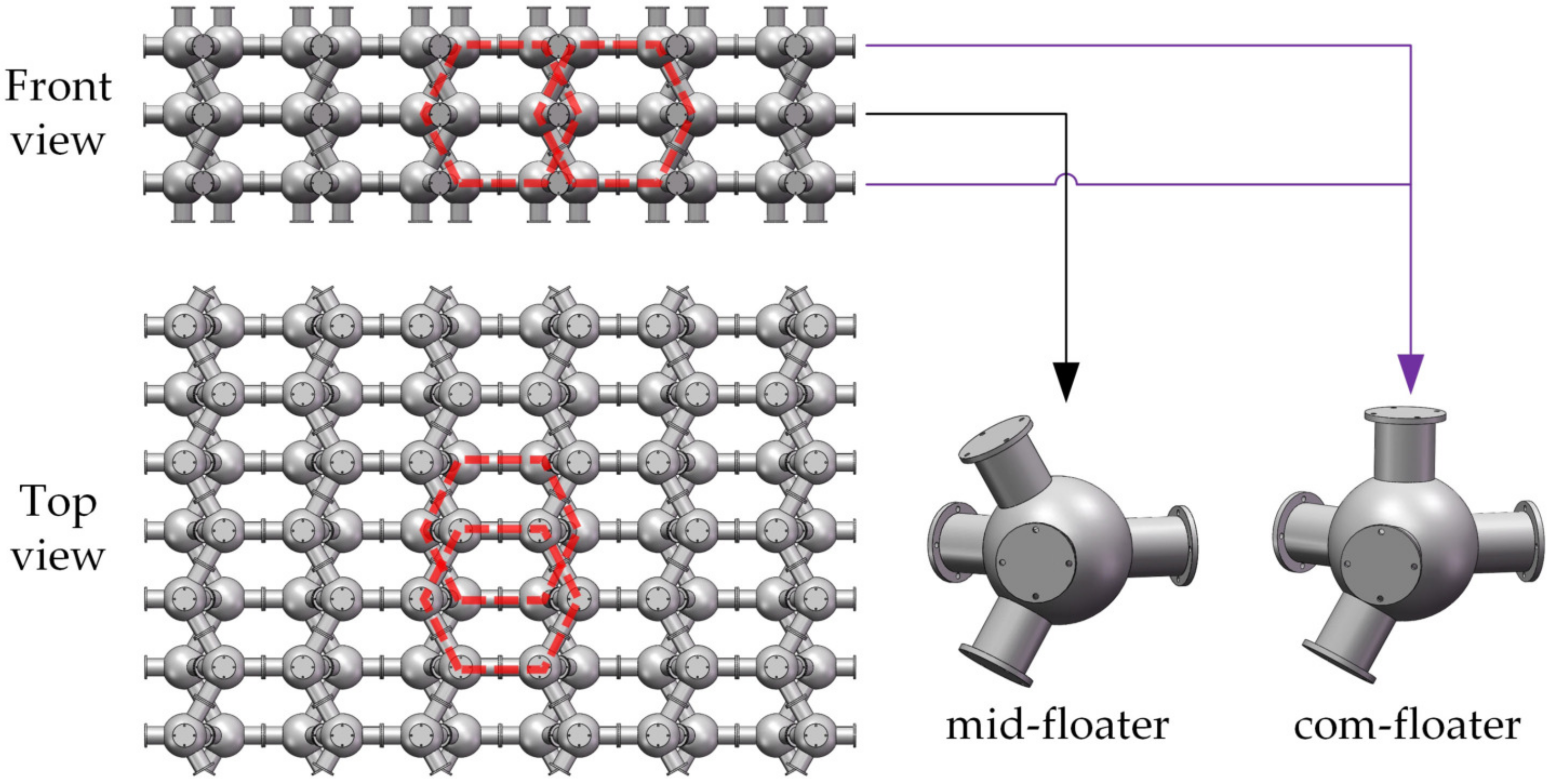
The floating system consists of the BDFF, an HVWT, the ballast, and mooring lines. The BDFF here is characterized by two components, i.e., the mid-floater and the com-floater, whose modularity is graphed in Figure 2.
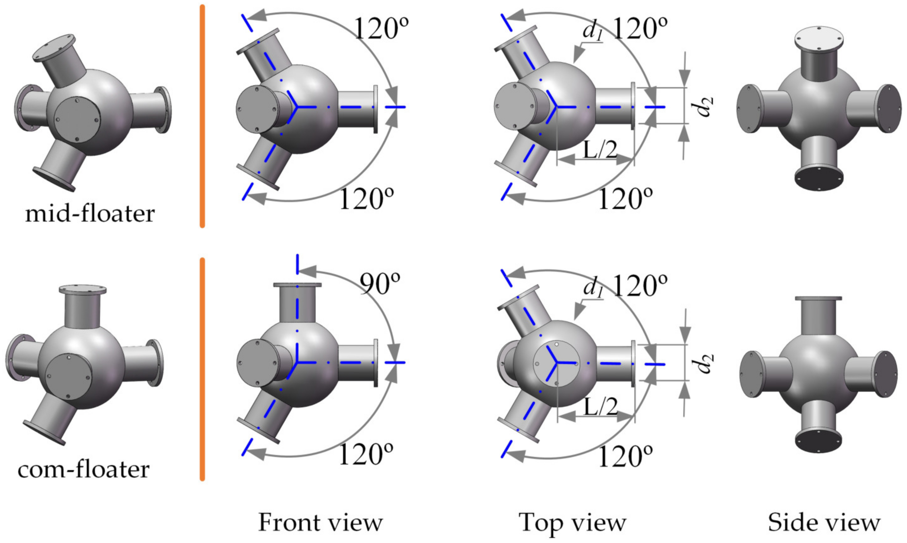
For a three-layer BDFF, the com-floaters are located at the upper and lower layer, while the mid-floaters are arranged in the middle layer. The entire structure can be considered as a grid structure with honeycombs both in front and top view, which contributes to the overall stiffness. During the construction, there is no need to rent a yard. All the floaters can be built entirely at the factory, transported with the existing logistics system, and assembled at the quayside. The modular design can make full use of the advantages of industrialized mass production. Meanwhile, the on-site operation time is considerably shortened, which effectively reduces the radical cost. Furthermore, similar to building blocks, the BDFF can be expanded in three directions. Compared to the SPAR and semi-submersible, the main benefits of the BDFF are the scalability and flexibility, providing a large deck area where the new energy equipment (e.g., the offshore hydrogen production equipment and the seawater desalination equipment) can be installed. As illustrated in Figure 3, the mid- and com-floater are different configurations but have identical key parameters: The diameter of spherical part d 1 and the diameter of cylindrical part d 2 , which are connected with specific rules. The com-floaters are included for assembly-supporting and upper connection with one cylinder facing the horizontal plane of the assembly. In addition, the number of the middle layer depends on the carrying capacity and the demand of the deck area since more than one middle layer can be deployed between the upper and lower layer. Therefore, the load capacity can be maintained by adjusting the middle layer and the size of each layer. If the length and width of each layer increase, the middle layers should be cut down or omitted. In this paper, we omitted the mid-floaters to obtain greater deck area reserved for solar panels in future research.
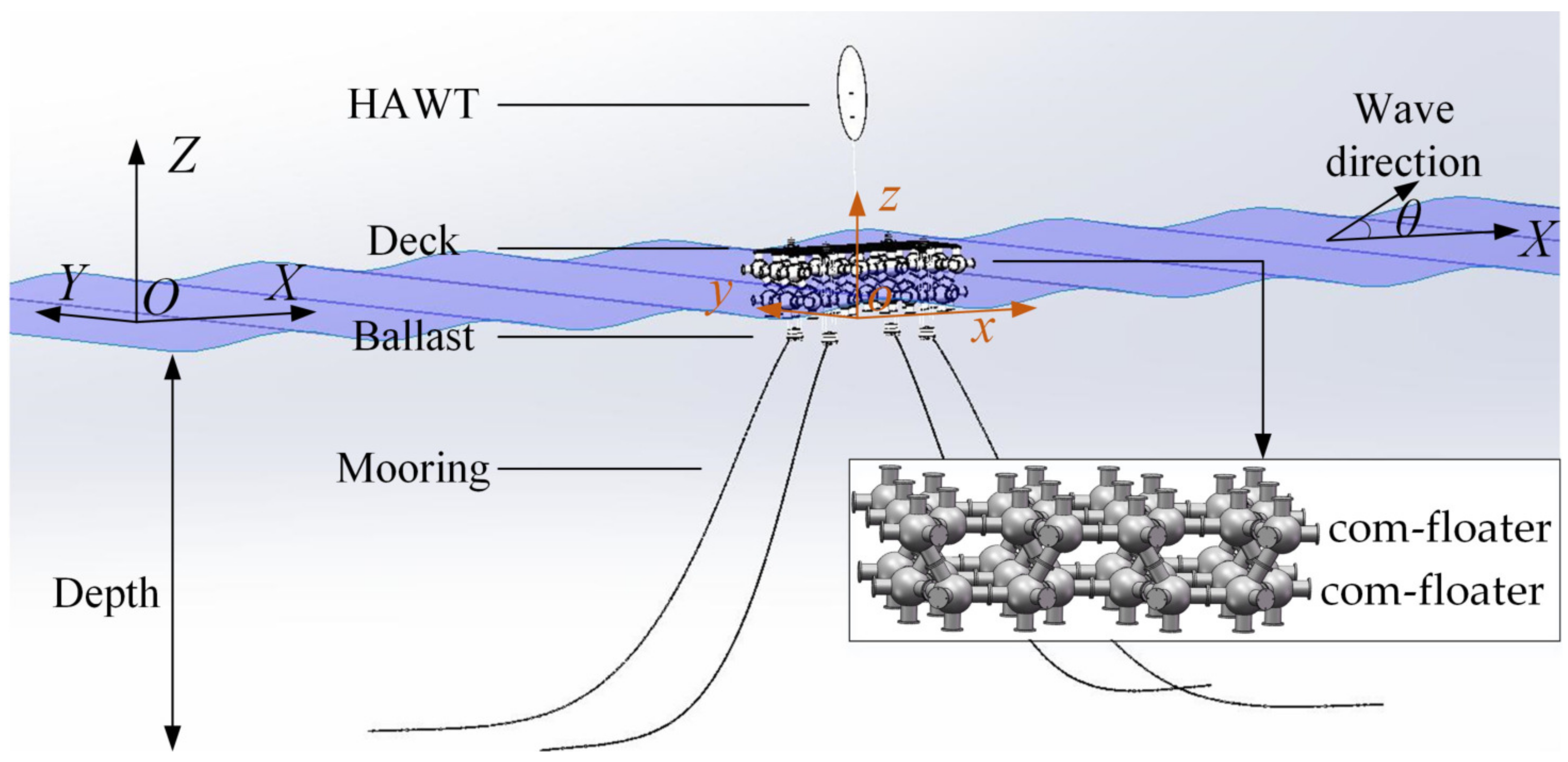
Meanwhile, the application of single configuration reduced manufacturing expenses. Furthermore, the hydrodynamic performances are similar for a bi-layer or three-layer BDFF because responses mainly rely on the underwater diffracted parts. The waves with different periods can easily pass through the BDFF without considering hogging and sagging. Additionally, a two-layer BDFF consisting of only com-floaters was applied in the floating system. In order to create sufficient buoyancy, twenty com-floaters were used to construct the BDFF as shown in Figure 4. Since half of the floaters were below the waterline, twenty separated inclined cylinders piercing the water reduces the cut-water plane area. The BDFF stiffness was further strengthened by connecting a truss deck where a simplified wind turbine was mounted, and four distributed ballasts were hung. The HVWT tower with mass of 2 t together with the nacel with mass of 2 t are considered a rigid body. Four catenary mooring cables made with stud-less chains were attached to the ballasts to restrict the floating system. For waves with small amplitudes, the BDFF for stability depends on the small cut-water plane. For waves with significant amplitudes, the BDFF for stability relies on buoyancy at a greater distance from the center-line.
The truss deck preserved for solar panels is not covered with solid plates like the coastal bridges researched by Istrati et al. [41]. On the one hand, the solid plates (i.e., one of the structural components of the complex bridge: Deck [41]) will restrict the water body when the wave inundates the offshore structure. The uplift force from the dynamic pressure caused by the restricted water body is high especially for a large deck area as well as the overturning moment on the offshore side. If the deck is large enough, there will be two wave valleys or peaks for the restricted water body simultaneously, which will bend the deck up or down. Furthermore, the overturning moment at the instant of the wave slamming on the deck should be cut down by increasing the porosity of the deck. On the other hand, the floaters were designed with streamlined balls and cylinders to minimize fluid resistance. For our model, the truss deck allows the waves to propagate forward unblockedly without considering the uplift force and over-topping. However, once the wind turbine is taken into account, the connections between the truss deck and the tower should be firm enough to transfer the wind forces and moments applied to the turbine. Therefore, future research studies should focus on the connection reliability when the floating foundation is subject to extreme weather like tsunami conditions.
The water depth was taken to be 50 m. A Cartesian coordinate system O-XYZ was fixed where the axes x coincides with the undisturbed water and the z-axis points upwards. A body coordinate system o-xyz has its origin at the center of gravity of the floating system. The included angle between the wave propagation direction and X-axis is θ . Since this paper mainly focuses on the hydrodynamic response of the BDFF, the interaction between the body and winds is ignored. The main parameters of the floating system and the properties of the mooring cables are summarized in vertical Table 2.

3. Theory Background

In this section, the calculation method of the force and corresponding motion responses based on the Laplace equation and boundary conditions are described detailly.

3.1. Potential Theory

Navier–Stokes (NS) equation is essentially the application of Newton’s Second Law (NSL) under the Euler system, which describes the relationship between the motion and the force.
ρ u t + ( u · ) u = p + μ 2 u + ρ g
where ρ is the fluid density, u is the fluid velocity, p is the fluid pressure, μ is the fluid dynamic viscosity. Hereafter, we assume the fluid is a continuous and homogeneous ideal fluid. That means the fluid should be irrotational, in-viscid, and in-compressible. The fluid velocity can be obtained by finding the gradient of the velocity potential φ = u . Then the NS equation can be simplified and written as the Bernoulli equation, together with which the Laplace equation can be solved.
ρ φ t + 1 2 ρ φ · φ + p + ρ g z = C t 2 φ = 0
where C t is a time-dependent constant. In order to describe the time-harmonic motions, a scalar velocity potential φ is introduced. For the linear small-amplitude wave harmonic in time with an angular frequency ω , the velocity potential can be expressed by the following form:
φ ( P , t ) = φ I ( P , t ) + φ D ( P , t ) + φ R ( P , t ) = Re φ ( P ) e i ω t
where the position P ( x , y , z ) is defined in the fixed reference axes. φ I ( P , t ) is the incident wave potential assuming that there is no floating body in the flow field; φ D ( P , t ) is the diffracted wave potential which is the velocity potential under the action of incident wave assuming that the floating body is fixed in the fluid field Ω ; φ R ( P , t ) is the radiation potential, assuming that there is no incident wave in the fluid field and the floating body is forced to move in the static fluid field.
As a continuous harmonic function, the usual potential φ separated from the time, can simplify the problem, and satisfy the Laplace equation and NS equations in the fluid domain. Functions that satisfy Laplace’s equation are often said to be harmonic. Therefore, simple harmonic functions can be superposed into a complex harmonic function. Here, the time-independent velocity potential φ is further divided into eight parts.
φ ( P ) = φ I ( P ) + φ D ( P ) + φ R ( P ) = φ 0 ( P ) ζ A + φ 7 ( P ) ζ A i ω j = 1 6 φ j ( P ) η j
where φ 0 and φ 7 are the incident and diffracted space-dependent potential with unit wave amplitude, respectively. ζ A is the incident wave amplitude of regular waves. η j represents the instantaneous displacement of floating body, η j = Re { η ¯ j e i ω t } . φ j ( j = 1 6 ) refers to the unit radiation potential corresponding to the j-th motion mode when the body moves with unit speed.
The variables are defined in the right-handed Cartesian coordinate system O-XYZ. The governing equation (i.e., the Laplace equation) and the boundary conditions are listed in Equation (5). The fluid field domain Ω consists of the average wetted surfaces of the floating body Γ b , the free surface Γ f , the seabed Γ d and the infinite artificial cylindrical surface Γ R .
Laplace equation : 2 φ = 0 , in Ω Linear free surface condition : φ z k φ = 0 , z = 0 Seabed surface condition : φ z = 0 , z = h Body wetted surface condition : φ j n = n j , j = 1 6 , for radiation , on Γ b φ 7 n = φ 0 n , for diffraction , on Γ b Far field radiation condition : lim R R ( φ R i k φ ) = 0 , R = x 2 + y 2
where k is the characterized wave number which is the solution of the dispersion relation ω 2 / g = k tanh k h . And η ˙ j refers to the body velocity of the j-th motion mode. n j is the generalized normal vector. Under the assumption of the linear free surface, a general expression of the incident wave potential in the Cartesian coordinate system for a regular wave of angular frequency ω propagating over a water depth of h can be derived, as the following form shows, from the first three equations in Equation (6).
φ I = g ζ A i ω cosh k ( z + h ) cosh k h e i k ( x cos θ + y sin θ )

3.2. Boundary Element Method

Using the indirect boundary element method, the velocity potential of any point P ( x , y , z ) in the domain Ω can be expressed by the function value and normal derivatives of point Q on the boundary.
φ j ( P ) = 1 4 π Ω φ j ( Q ) G ( P , Q ) n G ( P , Q ) φ j n d S , Ω = Γ f + Γ d + Γ b + Γ r
where G ( P , Q ) is a Green function satisfying the boundary conditions except the Γ b . Therefore, the boundary value problem has been transformed to a boundary integral equation problem. Then, when the mean wetted surface condition is applied on Equation (7), the following equation can be derived.
φ j ( P ) = 1 4 π Γ b σ ( Q ) G ( P , Q ) d S , P Γ b
where σ ( Q ) is the source strength of the location Q on Γ b . It means that the potential can be easily determined if enough source strengths are distributed on the average wetted body surface without considering other boundary condtions. Furthermore, σ ( Q ) can be obtained by the Fredholm integral equation.
φ j ( P ) n = 1 2 σ ( P ) + 1 4 π Γ b σ ( Q ) G ( P , Q ) n d S
Moreover, the irregular frequencies always appear in the solution of the BEM in the internal free surface and the gap between floaters, which will influence the stability. The singularity caused by the Green function can be eliminated by adding a damping force at the meshed free surface [42]. The AQWA codes utilize the flexible damping lid method to remove irregular frequencies [43,44]. Unreasonable overestimation values in the numerical results are suppressed to accurately and highly efficiently evaluate the hydrodynamic responses.

3.3. 3D Panel Method

By introducing the 3D panel method, the mean wetted surface Γ b is replaced by a collection of quadrilateral panels Δ Γ b i . The Hess-Smith method is used to keep the unknown potential, and source strengths within each quadrilateral are constant. The discretized Green integral equation is as follows:
φ j ( P k ) n = 1 2 σ k ( P k ) + 1 4 π i = 1 N σ i ( Q i ) G ( P k , Q i ) n Δ Γ b i , k = 1 N
where N is panel numbers. P k , Q i are both the centroid position of the planar quadrilateral. By this discretization, the differential equations can be replaced by a set of algebraic equations that the AQWA can solve. The velocity potential at any point can be obtained by interpolating between adjacent mesh element centers.

3.4. Wave Force

The first-order fluid pressure is determined from the simplified NS equation. By integrating the fluid pressure over the Γ b , the incident wave force, the diffracted wave force, and the radiation wave force can be easily calculated.
F I j = ρ Γ b φ I ( P , t ) t n j d S = Re i ρ ω ζ A Γ b φ 0 n j d S · e i ω t = Re F ¯ I j e i ω t F D j = ρ Γ b φ D ( P , t ) t n j d S = Re i ρ ω ζ A Γ b φ 7 n j d S · e i ω t = Re F ¯ D j e i ω t F R j = ρ Γ b φ R ( P , t ) t n j d S = k = 1 6 A j k η ¨ j + B j k η ˙ j
where Γ b is the mean wetted surface. A j k is the added mass, A j k = ρ Γ b Re [ φ k ] n j d S ; B j k is the radiation damping coefficients, B j k = ρ ω Γ b Im [ φ k ] n j d S . F ¯ represents a complex amplitude.
F W = F I + F D = Re i ρ ω Γ b ( φ 0 + φ 7 ) n j d S · e i ω t ζ A = F ζ A
where F is a transfer function that relates input wave amplitudes to output wave forces. The wave exciting force F W is comprised of the incident wave force and the diffracted wave force. In general, the numerical computation progress of wave forces above is concluded in Figure 5.

3.5. The Equation of Motion

The floating body in water is subjected to kinds of force, of which the wave exciting force F W is the acting force.
F j = M j k η ¨ j = F W j k = 1 6 A j k η ¨ j + B j k η ˙ j C j k η j
ω 2 ( M + A ) i ω B + C η = H η = F W
where C is the hydro-static stiffness. H is a transfer function that relates input wave forces to output motion responses.
H 1 = ω 2 ( M + A ) i ω B + C 1
A body in the motion includes six DOFs: Three translation DOFs named surge, sway and heave as well as three rotation DOFs called roll, pitch and yaw. The motion response of each DOF can be obtained by solving the equation of motion in Equation (14) based on Newton’s Second Law (NSL). From the incident wave to the motion response, the whole transfer function is written as H 1 F at a specific frequency. All variables are functions of frequency.
η = H 1 F W = H 1 F ζ A
Here, a dimensionless parameter called response amplitude operator, expressed by which equals the ratio of the motion amplitude η ¯ j to incident regular wave amplitude ζ A under different wave frequencies, is used to evaluate the stability performance in this paper. In general, the numerical computation progress of motion responses is concluded in Figure 6.
The free surface deformation in the extreme wave conditions will indeed cause the plunging waves and other breaking waves, which are highly non-linear wave phenomena involving air-water phases and turbulent flows. The AQWA solver based on the linear potential flow is a quick way to obtain the hydrodynamic response because of its robustness and high computational efficiency. It is difficult to for the potential flow solver to capture the wave–body interaction under large waves and breaking waves since the BEM cannot deal with such effects. However, the BEM for computing the velocity at the interface based on the non-linear potential flow model can be coupled with an interface capturing method like LSM or VOF to track the air-entrapment interface between two phases. A better approach is the CFD model based on the transient Navier–Stokes method along with the continuity equation. By discretizing the Reynolds-averaged Navier–Stokes (RANS) equations using the finite volume method, the non-linear free surface elevation, the effects of boundary layer viscous flow separation and turbulence can be accurately predicted. The aleatory uncertainty occurring in extreme conditions such as storms, hurricanes and tsunamis can be included in the CFD method but with high computation cost. It is very valuable to investigate the impact of breaking waves, broken waves and bores on the floating foundation to obtain survivability. As studied by references [41,45], the transient overtopping mechanism can help obtain the wave-induced forces and the motion constraining effects of nonlinearities. Moreover, the wave–body interaction by turbulence modeling considering the air compressibility [46] captures the non-linear effects of the two-phase air/water problem when subjected to Violent water wave impact. Therefore, the CFD model based on RANS will be employed to capture the wave breaking and overtopping in the future.

4. Results

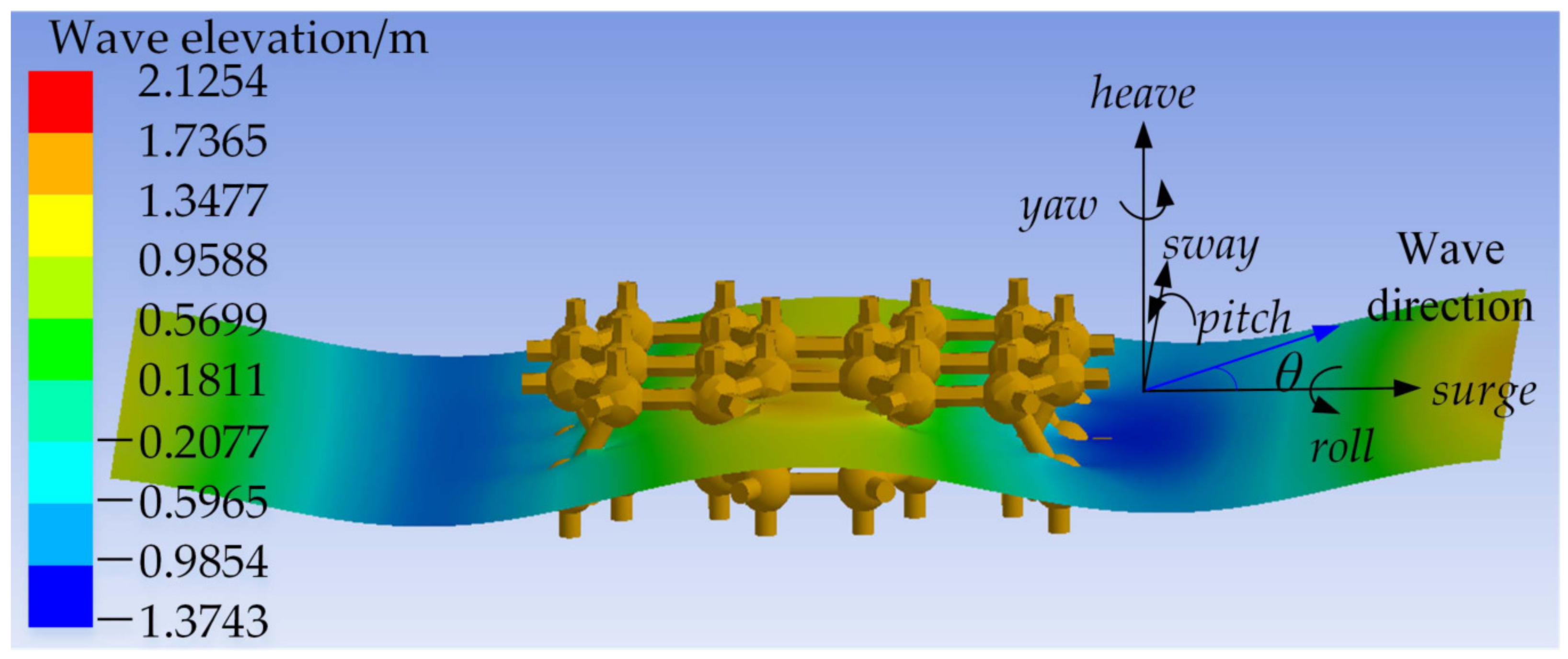
In this section, the hydrodynamic response of the floating system is presented. Different wave frequencies and directions are considered for performing the motion response simulation. An experimental campaign was conducted at the wave tank to verify the numerical results. The interaction between the BDFF and waves has been shown in Figure 7. The model was first modeled in SolidWorks, then imported to the AQWA as a surface body. The surface of the BDFF was divided into non-diffraction elements and diffraction elements, meeting the requirement that single wavelength covers more than seven units of mesh elements. Finer meshes were adopted near the water line.
The denser the mesh, the higher the accuracy of the calculation results. However, a dense mesh is a big challenge to the CPU. In addition, the AQWA solver limits the maximum number of total elements and diffracted elements to 40,000 and 30,000, respectively. A mesh independence study was performed to guarantee the calculation results converge. The model surface was meshed by quadrilateral dominant elements whose size were fine-tuned. Six mesh sizes were selected to as shown in Table 3. The relative errors with respect to the finest mesh (case 1) in peak pitch RAOs were used to compare the calculations. The 64-bit Windows system with five CPU cores was used to run the analysis. The model surface in case 1 was meshed by 35,769 quadrilateral dominant elements, of which the submerged part was divided into a total number of 27,301 panels. The relative error is less than 1% with respect to the finest mesh. Therefore, we believe the results converge to a solution that are independent of the mesh size.
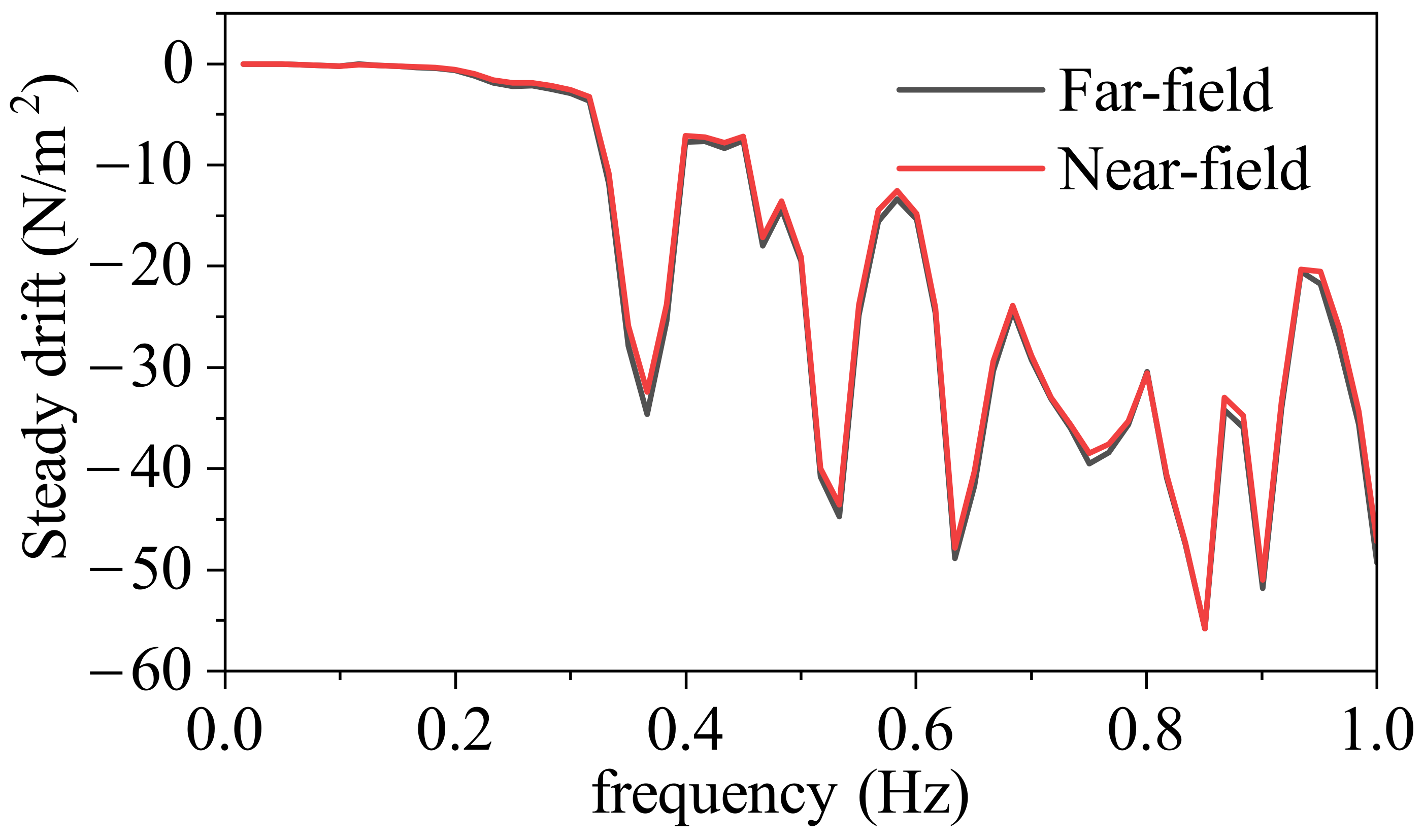
Furthermore, another direct method to decide whether the solution arrived converges is to compare the calculation results by near field method and far field method. The near field method calculate the integral of the pressure on the floating body which highly depends on the mesh quality, while the far field method calculate the momentum flux balance on the boundary of the fluid domain. As shown in Figure 8, the results of steady drift between near-field and far-field method agree well with each other.

4.1. RAOs under Different Wave Directions

The hydrodynamic response was affected by the wave-induced loads under different wave directions. The frequent extreme wave conditions make it urgent to know the direction sensitivity of structure response well. For floating structures like offshore horizontal axis wind turbines (HAWTs) and wave energy converters (WECs), the wave direction is not fixed since the waves are caused by random winds. Especially for HAWTs, the wind and waves have an included angle since wind waves caused by local wind are not always consistent with swell waves. The sensitivity in the structural response on wave directions as well as the internal stress was studied by Tomas et al. [47,48]. The mooring tension varies significantly under the effect of wave impact angle [49]. Furthermore, for firmly installed marine structures like bridges and breakwaters, the wave-induced forces and moment have significant changes under different incident wave directions [50,51]. The 3D effects of the force and moment is complicated due to the weak synchronization, which has a critical effect of the performance of marine structures. Moreover, the 3D effects on smooth low-crested structures of breakwaters are evident [52]. Therefore, it is necessary to perform a parametric investigation of the incident wave directionality.
The hydrodynamic response in regular waves can be expressed by the indicator of RAOs, which is defined as the motion response of the floating system subjected to a unit-amplitude wave height. The motion response near the equilibrium position was caused by low-order wave forces. In order to understand the structural sensitivity, the effects of changes in the wave directions and wave frequencies were analyzed. Since the system is symmetrical about the midstation plane and the centerline plane, only seven incident wave directions from 0 to 90 degrees with an interval of fifteen degrees were input to obtain the RAOs. The pitch and heave response are crucial factors for a floating system. In Figure 9a, the system’s pitch responses are plotted in a 3D diagram for a better overview. This contour plot shows the relationship between the wave frequencies and wave directions used to excite the waves and the pitch RAOs caused by waves. The red color has been used for higher RAOs while the purple color for lower RAOs.
It can be seen that the pitch RAOs have a significant value when the incident wave is the head wave, especially for low-frequency conditions. The peak pitch response is observed at 0.11 Hz, and the second maximum response appears at 0.27 Hz. Beyond the range of 0–0.6 Hz, the pitch motion dependents less on the wave frequencies and wave directions. Furthermore, the effect of wave direction on the pitch RAOs is gradually weakened except for some bumps in the mid-frequency band at around 45 degrees. As expected, there was no obvious effect on the surge direction when the system was subjected to the beam wave. The system’s heave RAOs are also analyzed within seven selected incident directions as graphed in Figure 9b. The effect of the wave direction on the heave response of the BDFF is not apparent. The general distribution of the heave responses shows large values in the low-frequency band, which are almost identical. The peak on the plot corresponds with the highest heave RAOs and occurs at approximately 0.09 Hz for all wave directions. The heave motion slows down in the high-frequency domain. In addition, as expected, the heave motion was less affected by the incident beam wave. This is due to the BDFF design that waves can get through the space between floaters. Therefore, the BDFF design is not sensitive to the incident wave directions.
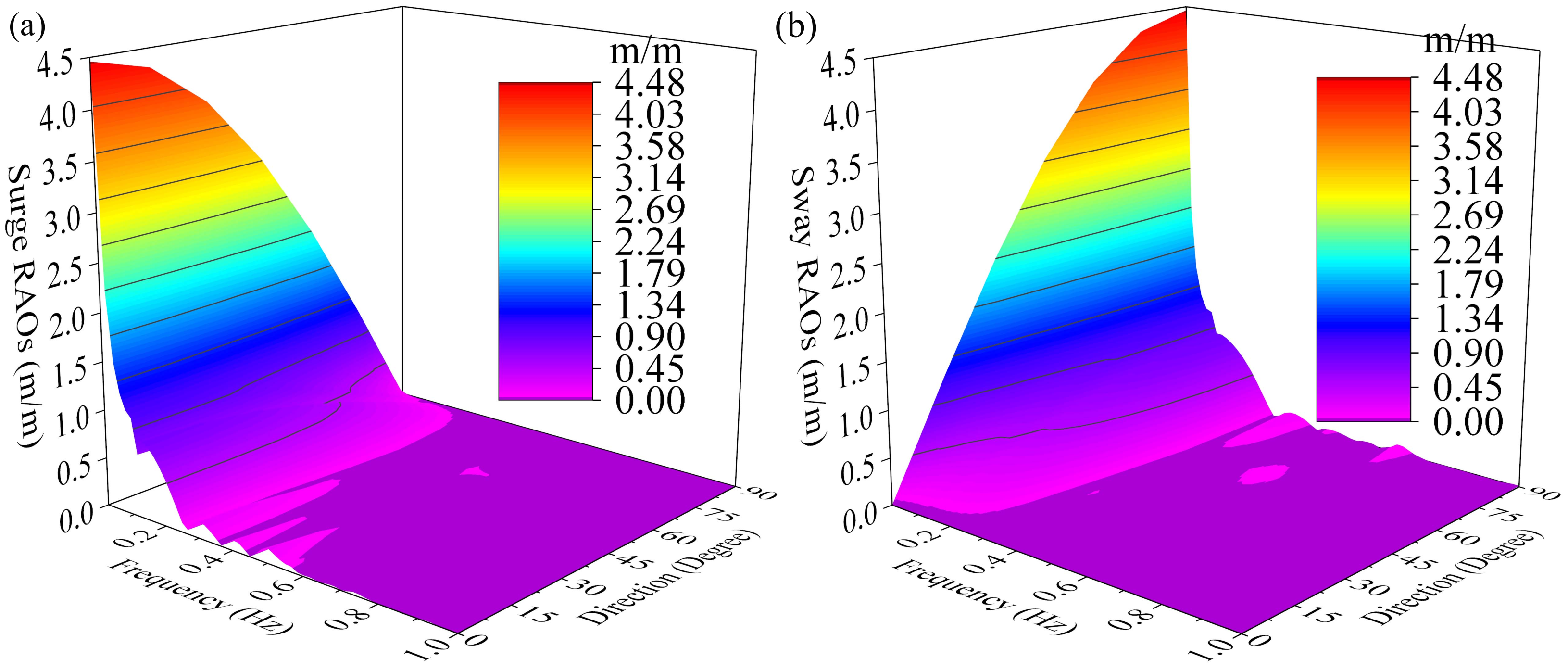
The roll RAOs under different wave directions are similar to the pitch ones. However, the roll RAOs shows significantly lower values due to a narrower overwidth. In addition, the surge and sway RAOs are presented in Figure 10a,b, respectively. The surge RAO at 0 degree wave is identical to the sway RAO at 90 degrees.

4.2. RAOs Comparison

Based on the Froude scaling laws, a model with a scale of 1:10 was made and tested in regular waves to investigate the influences of incident wave frequencies and wave heights. The experiments were conducted in a rectangular box-like wave basin of dimensions 25 m × 8 m, filled with water with a mean depth of five meters, as sketched in Figure 11. The absorbing beach is equipped to minimize the energetic reflections. The wavemaker can generate regular waves with frequencies varying from 0.28 Hz to 2.5 Hz with a limitation on wave height of 0.75 m. The test model in still water and head waves is presented in Figure 11b,c.
The test model fabricated by resin was regarded as a rigid body with an overall dimension of 2.16 m, 1.6 m, and 0.67 m. The dimensions of the scaled model and the mooring parameters were also sketched in Figure 11e. The fairlead radius, mooring radius and mooring length are 0.9 m, 6.5 m, and 7.5 m, respectively. Four non-contact motion capture camarers were installed at the basin side to measure the foundation’s response in the experiments. Three resistive-type wave gauges were used to measure the wave elevation. In order to guarantee the accuracy of incident waves, each wave was calibrated by wave gauges on the same line. Meanwhile, when the water plane absolutely calmed down, each wave case was conducted three times consecutively to obtain the average measure results.
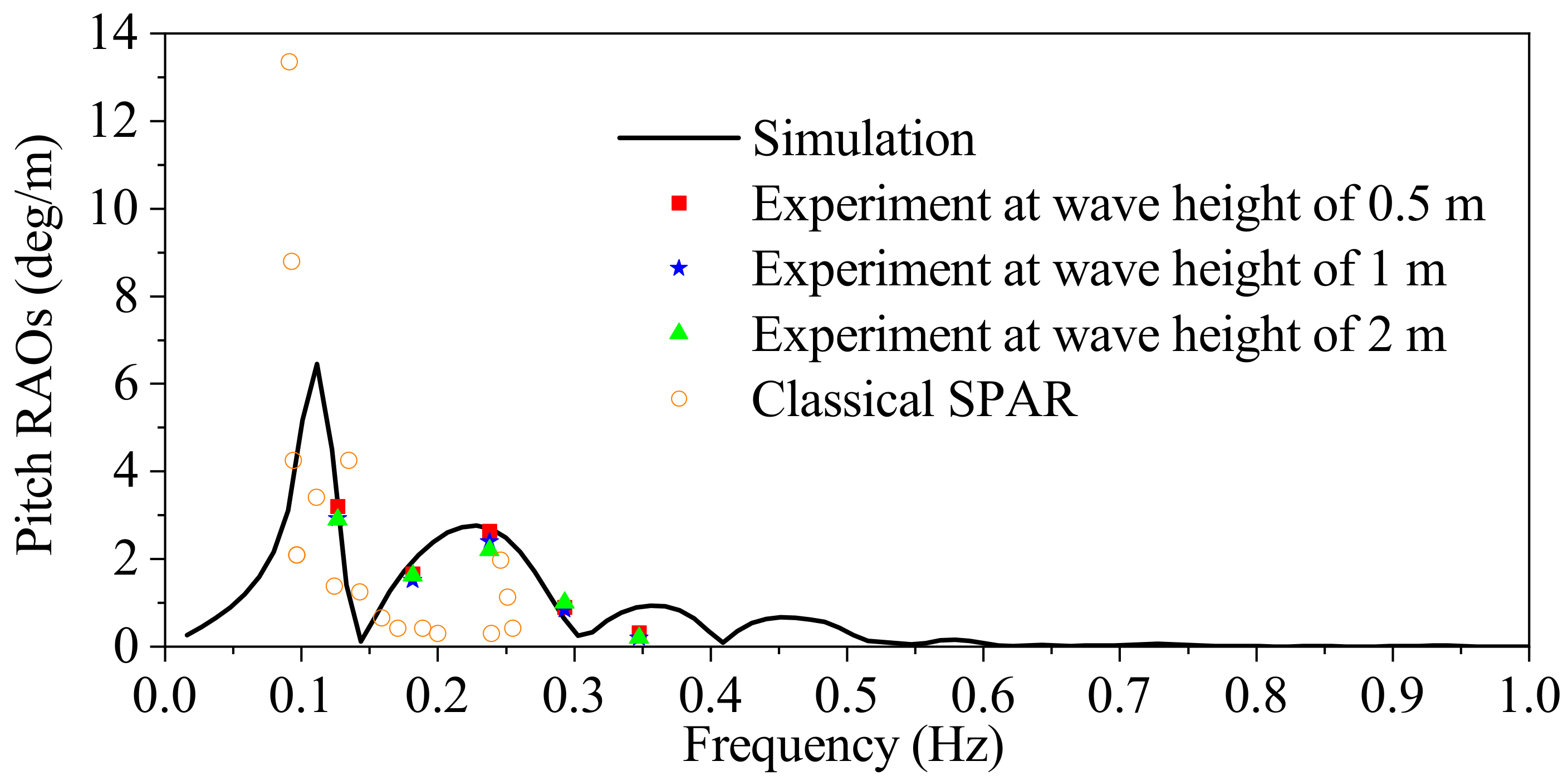
According to the 3D surface plots in the last subsection, the maximum response happens when the incident wave direction is zero degree. Therefore, the surge direction is chosen as the direction of the incident waves to guarantee the floating system is exposed to the maximum response. A comparison of the simulation results carried out with potential theory and the wave tank experiments is presented in Figure 12. While five wave conditions were used in the tests, the tendency of the RAOs is roughly the same as the numerical results. This indicates that the potential theory applyed on the BDFF in the simulation is reasonable. The numerical roughly agree with experimental results for the first four frequencies. For example, the pitch RAOs for the frequency 0.29 Hz have a large deviation for three wave heights. The numerical result is 2.7, while the experiment results are 2.64, 2.2, 2.4 with wave height of 0.5 m, 1 m, and 2 m, respectively. The maximum relative error is 11.1% for wave height of 1 m, while the minimum relative error is 2.2% for wave height of 0.5 m.
However, it should be noted that the numerical results slightly over-predict the response due to the assumption of ideal fluids. In addition, there are two characteristic length for the BDFF: One is the diameter of the spherical part of the floaters, and the other is the center-to-center sphere spacing which is the side length of the honeycomb. The diameter is small enough that most waves can be diffracted. The honeycombs of the BDFF will enclose the wave to create internal standing waves to dissipate wave energy, which brings about the second peak pitch response. Besides, there are distinct differences between the numerical and the experimental results for the fifth frequency 0.35 Hz. The diffraction ability of waves decreases with the decrease of wavelength. The wavelength of 12.75 m corresponding to 0.35 Hz is far less than the overall length of the BDFF. As a result, there are simultaneously two wave peaks or valleys in the BDFF. On the one hand, the uplift or drop forces generated by the dynamic pressure can balance the BDFF well. This is similar to the case presented by Xiang et al. [53] that the uplift hydrodynamic loads greatly depend on the ratio of the wavelength-to-the-width of the structure, especially when the wavelength was shorter than the structural width. On the other hand, the standing waves formed in the honeycomb are intensive due to a large small wave steep. The energy dissipation by wave break can not be captured by the potential theory. Therefore, the pitch response in the experiments is much smaller than that in the simulation for the frequency 0.35 Hz.
Furthermore, representative results for a variety of wave conditions in the study of Kurian et al. [54] were used to evaluate the proposed floating system. As seen for the comparison of the proposed floating system and the classical SPAR, the proposed system behaves better around 0.1 Hz. With the increase of wavelength, the classical SPAR increases the pitch response. However, for a frequency range that is greater than 0.15 Hz, it can be seen that the the classical SPAR has noticeably small pitch RAOs except for the response around 0.25 Hz. In general, the proposed system shows an acceptable pitch response.
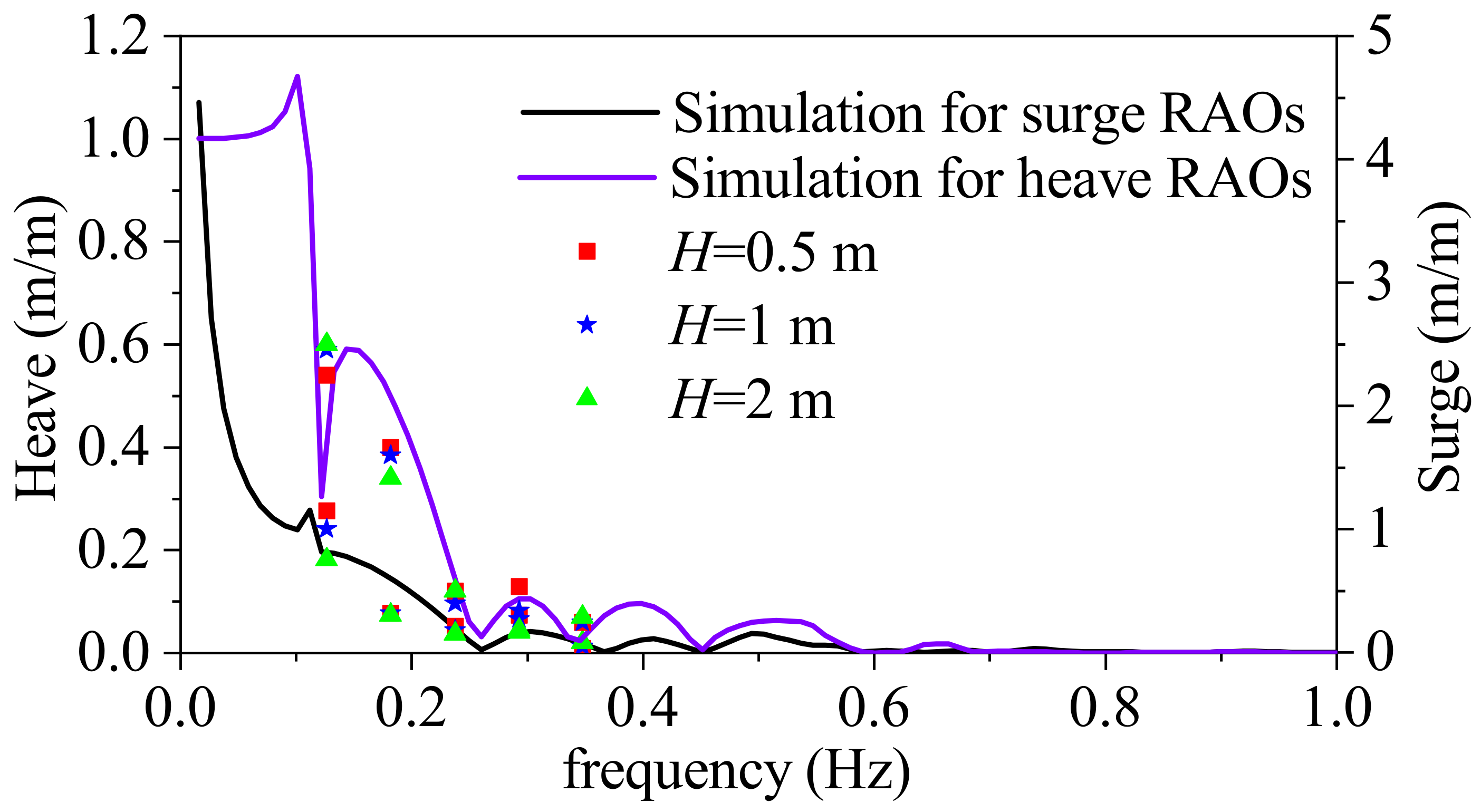
The comparisons between other RAOs such as heave and surge motion are also expanded in Figure 13. The surge RAOs decreases with the increase of frequencies. The heave RAOs have a similar downward tendency but two significant peaks at low frequencies. Moreover, the time-domain analysis at fundamental frequencies will be conducted in the future to understand the effectiveness of the BEM.

4.3. Symmetry and Coupling

The BDFF has longitudinal and transversal symmetrical planes at the same time. Wang et al. [55] explained the coupling relationship very well. For the test model, as a result of transversal symmetrical characteristics, the six motion equations can be divided into two sets, one of which includes sway, roll, and yaw, and the other contains surge, heave, and pitch. Furthermore, due to the longitudinal symmetrical characteristics, the motion equations can also be split into two sets, one of which contains surge, pitch, and yaw, and the other covers sway, heave, and roll. There is no coupling between two sets reflected in the coefficient matrix, like the added mass and radiation damping. The pitch motion is not influenced by the roll and sway motion which has been validated in the subsection above. In the situation of double symmetry, the heave motion is the only translational degree that is not coupled with other degrees. Meanwhile, the yaw motion is the only rotational degree that is not coupled with other degrees. As a result, the heave or yaw motion can be simplified as a single DOF system like the spring-mass system at the beginning of the structure design to analyze and optimize the offshore structure. However, for an offshore HVWT, the yaw motion can be controlled and adjusted by the yaw system to cater to the wind direction, while the heave motion without an active ballast system can not be adjusted easily. Therefore, the couple relationship of heave motion should be verified for heave response.
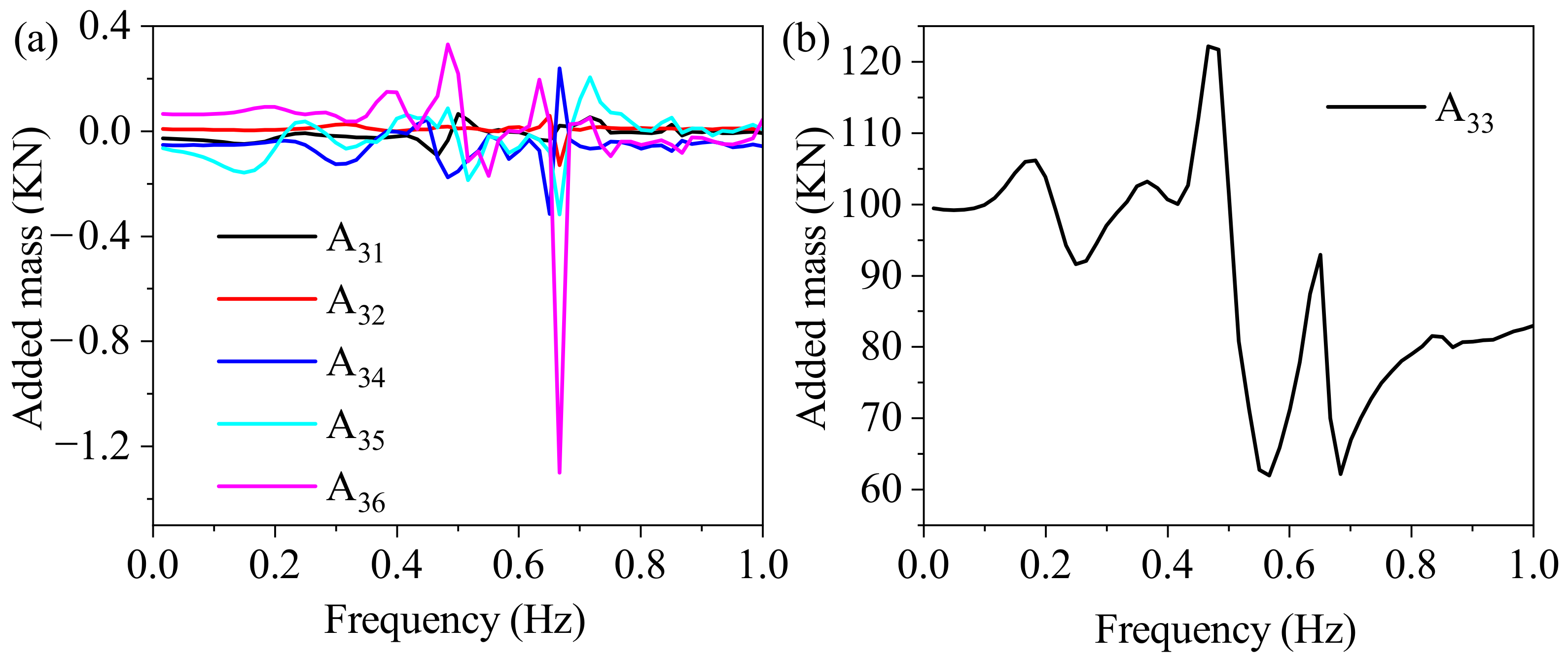
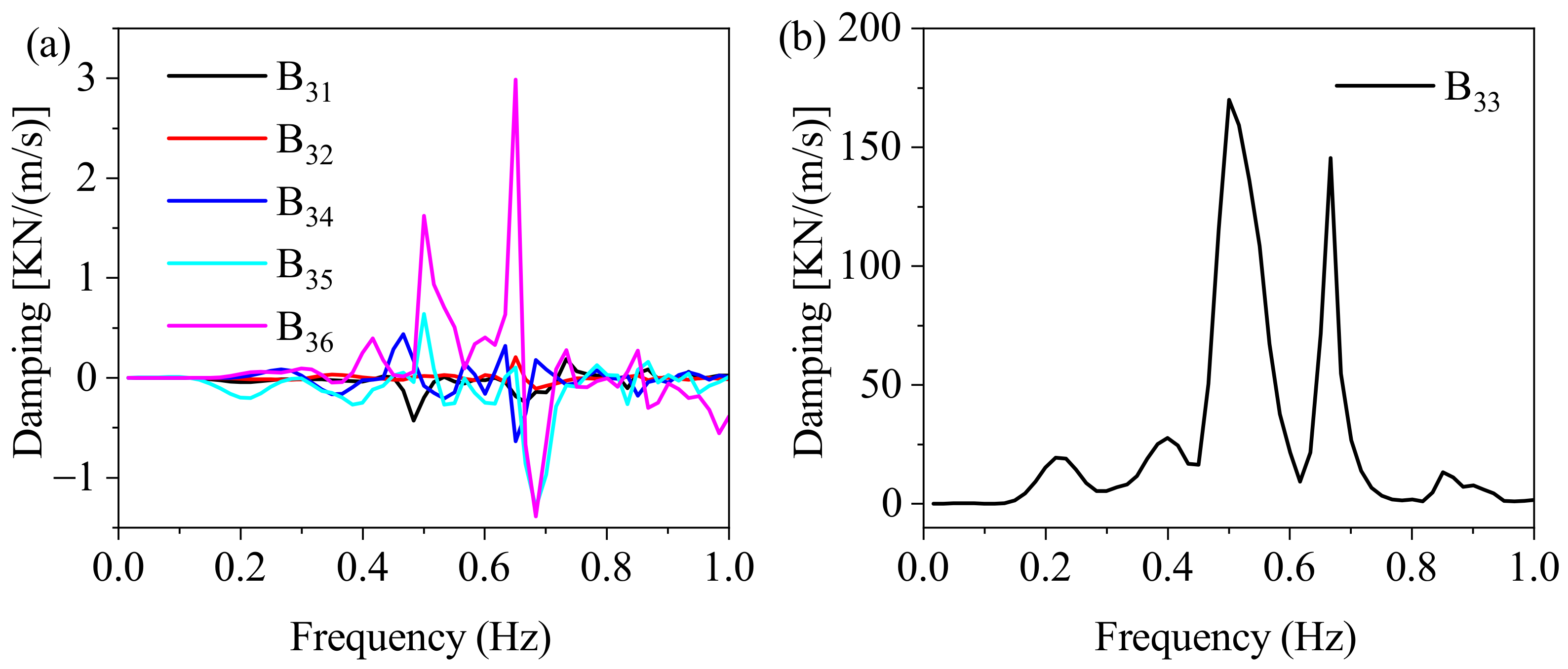
As shown in Figure 14 and Figure 15, the heave motion can be decoupled from the other five motions due to the longitudinal symmetry. For instance, the heave added mass coefficient A 3 j and the heave radiation damping coefficient B 3 j were calculated. The added mass is frequency-dependent. Figure 14b presents the added mass A 33 of heave motion. The other five added mass are given in Figure 14a. Similarly, Figure 15b illustrates the radiation damping coefficient B 33 of heave motion. Moreover, the other five damping coefficients are depicted. Both coefficients in Figure 14a and Figure 15a are close to zero compared to A 33 and B 33 , respectively. That is to say: The heave motion can be decoupled. Furthermore, the wave-free characteristic of heave motion exists at a particular wave frequency.
Frequency-dependent added mass has non-zero values at all frequencies. Frequency-dependent radiation damping coefficient disappears at low and high frequencies. The wave-structure interaction for multiple inclined cylinders piercing the water plane is significantly more complex than for a single floater like the boat. There are three crucial lengths for the BDFF: The minimum center-to-center sphere spacing of 3.6 m, the maximum center-to-center sphere spacing of 7.2 m, and the opposite edge distance of the regular hexagon of 6.23 m, which can shed light on the behavior of the hydrodynamic coefficients. The added mass and radiation damping coefficient has two clear peaks around 0.46–0.50 Hz and 0.66 Hz. The wavelength corresponding to 0.46 Hz is 7.17 m which is close to the maximum center-to-center sphere spacing. The wavelength corresponding to 0.5 Hz is 6.25 m which is roughly the same length as the opposite edge distance of the hexagon. The wavelength corresponding to 0.66 Hz is 3.6 m which equals the minimum center-to-center sphere spacing. When waves at these frequencies flow through the BDFF, standing waves appear due to the reflection in the regular hexagon, which will contribute to the intensive vibration of the BDFF. Therefore, the added mass and the radiation damping coefficient have two significant peaks.

5. Conclusions

This paper describes a floating system based on the BDFF concept, which can be scalable flexibly. The BEM and 3D panel methods were employed to evaluate the hydrodynamic performance of the floating system in regular waves. The wave basin experiments were implemented to validate the performance. The following conclusions can be drawn from the above analysis:
  • The pitch response on the surge direction is influenced significantly by the wave directions, while the surge response is less impacted. General trends of the pitch and heave responses both decrease with the increase of wave frequencies.
  • Regular wave test results show that the pitch RAOs agree well with the numerical results of the potential theory. The proposed floating system behaves well in the low-frequency band, while a classical SPAR has a better performance in the mid-frequency band.
  • The coupling relationship between six degrees of freedom shows that the BDFF can be decoupled to make the structure easy to analyze due to the symmetrical design.
Future work will focus on the following aspects:
  • The structural optimization of floaters [34]: Since the overall size and structural properties strongly rely on the floaters, it is important to analyze the influence of the floater spacing, the floater diameter, and the foundation width/length to finally decrease the hydrodynamic response.
  • The effect of mooring stiffness on the fluid–structure interaction: Since the nonlinear restoring forces are caused by the excursions of the COG, the wave–body interactions are significantly influenced by the mooring stiffness [56].
  • The dependence of the hydrodynamic performance on the wave type: The impact forces caused by unbroken and broken waves are different [45]. In addition, the short crest waves with large wave steep will impact the floating foundation and break.
  • The collision stability of the foundation under the attack of uncontrolled offshore objects: Moving offshore objects out of control will destroy the floating foundation under extreme conditions [57,58,59].
  • The sea-keeping ability under irregular waves: The irregular waves are combinations of regular waves with different wave properties.

Author Contributions

X.Q.: Validation, Data curation, Writing Original draft preparation. Y.Y.: Conceptualization, Supervision, Review and Editing. All authors have read and agreed to the published version of the manuscript.

Funding

This research was funded by the Science and Technology Planning Project of Shenzhen Municipality (Grant No.: JSGG20200701095002004).

Institutional Review Board Statement

Not applicable.

Informed Consent Statement

Not applicable.

Data Availability Statement

Not applicable.

Conflicts of Interest

The authors declare no conflict of interest.

Abbreviations

The following abbreviations are used in this manuscript:
BDFFBuoyancy distributed floating foundation
BEMBoundary element method
COGCenter of gravity
DOFsDegrees of freedom
Eq.Equation
HDPEHigh density polyethylen
HVWTHorizontal vertical wind turbine
MOIMoment of inertia
NSLNewton’s Second Law
RAOResponse amplitude operator
WECWave energy converter

References

  1. Arapogianni, A.; Genachte, A.B.; Ochagavia, R.M.; Vergara, J.P.; Castell, D.; Tsouroukdissian, A.R.; Korbijn, J.; Bolleman, N.; Huera-Huarte, F.J.; Schuon, F.; et al. Deep Water—The Next Step for Offshore Wind Energy; European Wind Energy Association: Brussels, Belgium, 2013; pp. 972–978. [Google Scholar]
  2. Komatsu, M.; Kumamoto, H.; Ohta, M.; Tanaka, H.; Mori, H.; Miyazaki, S. Development of offshore wind turbine floater that blends into Japanese waters. Mitsubishi Heavy Ind. Tech. Rev. 2016, 53, 30–39. [Google Scholar]
  3. Bluewater. Floating Wind Systems. Available online: https://www.bluewater.com/products-technology/floating-wind-systems/ (accessed on 20 December 2021).
  4. Amate, J.; Sánchez, G.D.; González, G. Development of a semi-submersible barge for the installation of a TLP floating substructure. TLPWIND® case study. J. Phys. Conf. Ser. 2016, 749, 012016. [Google Scholar] [CrossRef]
  5. Vita, L.; Ramachandran, G.; Krieger, A.; Kvittem, M.I.; Merino, D.; Cross-Whiter, J.; Ackers, B.B. Comparison of numerical models and verification against experimental data, using Pelastar TLP concept. In Proceedings of the International Conference on Offshore Mechanics and Arctic Engineering, St. John’s, NL, Canada, 31 May–5 June 2015; Volume 56574, p. V009T09A047. [Google Scholar] [CrossRef]
  6. Huber, F. The first floating wind turbines. In Proceedings of the 2nd International Conference on Ocean Energy (ICOE 2008), Brest, France, 15–17 October 2008; pp. 15–17. [Google Scholar]
  7. Adam, F.; Walia, D.; Hartmann, H.; Schünemann, P.; Großmann, J. A novel modular tlp-design for offshore wind turbines using ultra high performance concrete. In Proceedings of the ACMSM25—25th Australasian Conference on Mechanics of Structures and Materials, Brisbane, QLD, Australia, 4–7 December 2018; Wang, C.M., Ho, J.C., Kitipornchai, S., Eds.; Springer: Singapore, 2020; pp. 257–268. [Google Scholar] [CrossRef]
  8. Iv-Groep. Self-Installing Floating Wind Turbines. Available online: https://iv-groep.nl/en/blog/2020/zelf-installerende-drijvende-windmolens (accessed on 20 December 2021).
  9. Equinor. Industrialising Floating Offshore Wind. Available online: https://www.equinor.com/en/what-we-do/floating-wind.html (accessed on 20 December 2021).
  10. Hao, K.J.; Robertson, A.N.; Jonkman, J.; Driscoll, F.; Ng, E.Y.K. Building and calibration of a fast model of the SWAY prototype floating wind turbine. In Proceedings of the 2013 International Conference on Renewable Energy Research and Applications (ICRERA), Madrid, Spain, 20–23 October 2013; pp. 788–793. [Google Scholar] [CrossRef]
  11. Koh, H.; Lim, Y. Floating performance stage at the Marina Bay, Singapore. In Large Floating Structures; Springer: Singapore, 2015; pp. 37–59. [Google Scholar] [CrossRef]
  12. Kosasih, K.M.A.; Suzuki, H.; Niizato, H.; Okubo, S. Demonstration experiment and numerical simulation analysis of full-scale barge-type floating offshore wind turbine. J. Mar. Sci. Eng. 2020, 8, 880. [Google Scholar] [CrossRef]
  13. Henderson, A.R.; Zaaijer, M.; Bulder, B.; Pierik, J.; Huijsmans, R.; van Hees, M.; Snijders, E.; Wijnants, G.H.; Wolf, M.J. Floating windfarms for shallow offshore sites. In Proceedings of the Fourteenth International Offshore and Polar Engineering Conference, Toulon, France, 23–28 May 2004. [Google Scholar]
  14. Robertson, A.; Jonkman, J.; Masciola, M.; Song, H.; Goupee, A.; Coulling, A.; Luan, C. Definition of the Semisubmersible Floating System for Phase II of OC4; Technical Report; National Renewable Energy Lab. (NREL): Golden, CO, USA, 2014. [CrossRef] [Green Version]
  15. Galván, J.; Sánchez-Lara, M.; Mendikoa, I.; Pérez-Morán, G.; Nava, V.; Rodríguez-Arias, R. NAUTILUS-DTU10 MW Floating Offshore Wind Turbine at Gulf of Maine: Public numerical models of an actively ballasted semisubmersible. J. Phys. Conf. Ser. 2018, 1102, 012015. [Google Scholar] [CrossRef]
  16. Roddier, D.; Cermelli, C.; Aubault, A.; Weinstein, A. WindFloat: A floating foundation for offshore wind turbines. J. Renew. Sustain. Energy 2010, 2, 033104. [Google Scholar] [CrossRef]
  17. Legaz, M.J.; Coronil, D.; Mayorga, P.; Fernández, J. Study of a hybrid renewable energy platform: W2Power. In Proceedings of the ASME 2018 37th International Conference on Ocean, Offshore and Arctic Engineering, Madrid, Spain, 17–22 June 2018; p. V11AT12A040. [Google Scholar] [CrossRef]
  18. Lefranc, M.; Torud, A. Three wind turbines on one floating unit, feasibility, design and cost. In Proceedings of the OTC Offshore Technology Conference, Houston, TX, USA, 2–5 May 2011; p. OTC-21485-MS. [Google Scholar] [CrossRef]
  19. Huijs, F.; de Bruijn, R.; Savenije, F. Concept design verification of a semi-submersible floating wind turbine using coupled simulations. Energy Procedia 2014, 53, 2–12. [Google Scholar] [CrossRef] [Green Version]
  20. Sarlak, H.; Pegalajar-Jurado, A.; Bredmose, H. CFD simulations of a newly developed floating offshore wind turbine platform using OpenFOAM. In Proceedings of the 21st Australasian Fluid Mechanics Conference, Adelaide, Australia, 10–13 December 2018. [Google Scholar]
  21. Hexicon. TwinWind: Maximising Production, Reducing Cost, Motion Performance. Available online: https://www.hexicon.eu/twinwind/ (accessed on 20 December 2021).
  22. Le Boulluec, M.; Ohana, J.; Martin, A.; Houmard, A. Tank testing of a new concept of floating offshore wind turbine. In Proceedings of the ASME 2013 32nd International Conference on Ocean, Offshore and Arctic Engineering, Nantes, France, 9–14 June 2013; Volume 55423, p. V008T09A100. [Google Scholar] [CrossRef]
  23. Baita-Saavedra, E.; Cordal-Iglesias, D.; Filgueira-Vizoso, A.; Morató, À.; Lamas-Galdo, I.; Ȧlvarez-Feal, C.; Carral, L.; Castro-Santos, L. An economic analysis of an innovative floating offshore wind platform built with concrete: The SATH platform. Appl. Sci. 2020, 10, 3678. [Google Scholar] [CrossRef]
  24. Liu, Z.; Fan, Y.; Wang, W.; Qian, G. Numerical study of a proposed semi-submersible floating platform with different numbers of offset columns based on the deepcwind prototype for improving the wave-resistance ability. Appl. Sci. 2019, 9, 1255. [Google Scholar] [CrossRef] [Green Version]
  25. Adam, F.; Myland, T.; Schuldt, B.; Großmann, J.; Dahlhaus, F. Evaluation of internal force superposition on a TLP for wind turbines. Renew. Energy 2014, 71, 271–275. [Google Scholar] [CrossRef]
  26. Sahu, A.; Yadav, N.; Sudhakar, K. Floating photovoltaic power plant: A review. Renew. Sustain. Energy Rev. 2016, 66, 815–824. [Google Scholar] [CrossRef]
  27. Özgür, K. Modular Floating Buoy System with Multi-Layered Swing Mechanism for Stabilization of Offshore Platform. International Patent Application No. PCT/TR2016/050501, 17 May 2018. [Google Scholar]
  28. Float Inc. The PSP (Pneumatically Stabilized Platform) Technology. Available online: http://www.floatinc.com/PSPTechnology.aspx (accessed on 20 December 2021).
  29. Crema, I.; Simonetti, I.; Cappietti, L.; Oumeraci, H. Laboratory experiments on oscillating water column wave energy converters integrated in a very large floating structure. In Proceedings of the 11th European Wave and Tidal Energy Conference, Nantes, France, 6–11 September 2015; pp. 6–11. [Google Scholar]
  30. Hao, H.; Guo, Z.; Liao, K.; Xu, G. Studies on the initial stability of an air-cushion supported floating platform for offshore wind turbine. In Proceedings of the Thirteenth ISOPE Pacific/Asia Offshore Mechanics Symposium, Jeju, Korea, 14–17 October 2018. [Google Scholar]
  31. Diendorfer, C.; Haider, M.; Lauermann, M. Performance analysis of offshore solar power plants. Energy Procedia 2014, 49, 2462–2471. [Google Scholar] [CrossRef] [Green Version]
  32. Pakozdi, C.; Kendon, T.E.; Stansberg, C.T. Breaking Wave Impact on a Platform Column: An Introductory CFD Study. In Proceedings of the ASME 2011 30th International Conference on Ocean, Offshore and Arctic Engineering, Rotterdam, The Netherlands, 19–24 June 2011; pp. 645–654. [Google Scholar] [CrossRef]
  33. Zhang, H.; Zhou, B.; Vogel, C.; Willden, R.; Zang, J.; Zhang, L. Hydrodynamic performance of a floating breakwater as an oscillating-buoy type wave energy converter. Appl. Energy 2020, 257, 113996. [Google Scholar] [CrossRef]
  34. Xiang, T.; Istrati, D.; Yim, S.C.; Buckle, I.G.; Lomonaco, P. Tsunami loads on a representative coastal bridge deck: Experimental study and validation of design equations. J. Waterw. Port Coast. Ocean. Eng. 2020, 146, 04020022. [Google Scholar] [CrossRef]
  35. Vijay, K.; Venkateswarlu, V.; Nishad, C.S. Wave scattering by inverted trapezoidal porous boxes using dual boundary element method. Ocean Eng. 2021, 219, 108149. [Google Scholar] [CrossRef]
  36. Pan, K.; IJzermans, R.; Jones, B.; Thyagarajan, A.; Van Beest, B.; Williams, J. Application of the SPH method to solitary wave impact on an offshore platform. Comput. Part. Mech. 2016, 3, 155–166. [Google Scholar] [CrossRef] [Green Version]
  37. Canelas, R.; Ferreira, R.; Crespo, A.; Domínguez, J. A generalized SPH-DEM discretization for the modelling of complex multiphasic free surface flows. In Proceedings of the 8th International SPHERIC Workshop, Trondheim, Norway, 4–6 June 2013; pp. 74–79. [Google Scholar]
  38. Hasanpour, A.; Istrati, D.; Buckle, I. Coupled SPH–FEM modeling of tsunami-borne large debris flow and impact on coastal structures. J. Mar. Sci. Eng. 2021, 9, 1068. [Google Scholar] [CrossRef]
  39. Anagnostopoulos, S. Dynamic response of offshore platforms to extreme waves including fluid–structure interaction. Eng. Struct. 1982, 4, 179–185. [Google Scholar] [CrossRef]
  40. Istrati, D.; Buckle, I.G. Effect of fluid–structure interaction on connection forces in bridges due to tsunami loads. In Proceedings of the 30th US-Japan Bridge Engineering Workshop, Washington, DC, USA, 21–23 October 2014; pp. 21–23. [Google Scholar]
  41. Istrati, D.; Buckle, I.; Lomonaco, P.; Yim, S. Deciphering the tsunami wave impact and associated connection forces in open-girder coastal bridges. J. Mar. Sci. Eng. 2018, 6, 148. [Google Scholar] [CrossRef] [Green Version]
  42. Peña, B.; McDougall, A. An investigation into the limitations of the panel method and the gap effect for a fixed and a floating structure subject to waves. In Proceedings of the ASME 2016 35th International Conference on Ocean, Offshore and Arctic Engineering, Busan, Korea, 19–24 June 2016; p. V007T06A048. [Google Scholar] [CrossRef] [Green Version]
  43. ANSYS-Inc. AQWA User’s Manual Release 18.0; ANSYS-Inc.: Washington County, PA, USA, 2017. [Google Scholar]
  44. Chen, M.; Guo, H.; Wang, R.; Tao, R.; Cheng, N. Effects of gap resonance on the hydrodynamics and dynamics of a multi-module floating system with narrow gaps. J. Mar. Sci. Eng. 2021, 9, 1256. [Google Scholar] [CrossRef]
  45. Istrati, D. Large-Scale Experiments of Tsunami Inundation of Bridges including Fluid-Structure-Interaction. Ph.D. Thesis, University of Nevada, Reno, NV, USA, 2017. [Google Scholar]
  46. Peregrine, D.; Bredmose, H.; Bullock, G.; Obrhai, C.; Müller, G.; Wolters, G. Water wave impact on walls and the role of air. In Proceedings of the 29th International Conference on Coastal Engineering, Lisbon, Portugal, 19–24 September 2004; pp. 4005–4017. [Google Scholar] [CrossRef]
  47. Viuff, T.; Leira, B.J.; Xiang, X.; Øiseth, O. Effects of wave directionality on extreme response for a long end-anchored floating bridge. Appl. Ocean Res. 2019, 90, 101843. [Google Scholar] [CrossRef]
  48. Lyu, G.; Zhang, H.; Li, J. Effects of incident wind/wave directions on dynamic response of a SPAR-type floating offshore wind turbine system. Acta Mech. Sin. 2019, 35, 954–963. [Google Scholar] [CrossRef] [Green Version]
  49. Rudman, M.; Cleary, P. Oblique impact of rogue waves on a floating platform. In Proceedings of the International Offshore and Polar Engineering Conference, Osaka, Japan, 21–26 July 2009; pp. 572–579. [Google Scholar]
  50. Istrati, D.; Buckle, I.G. Tsunami Loads on Straight and Skewed Bridges–Part 1: Experimental Investigation and Design Recommendations; Technical Report No. FHWA-OR-RD-21-12; Oregon Department of Transportation Research Section: Washington, DC, USA, 2021. [Google Scholar]
  51. Istrati, D.; Buckle, I.G. Tsunami Loads on Straight and Skewed Bridges–Part 2: Experimental Investigation and Design Recommendations; Technical Report No. FHWA-OR-RD-21-13; Oregon Department of Transportation Research Section: Washington, DC, USA, 2021. [Google Scholar]
  52. Van der Meer, J.W.; Briganti, R.; Zanuttigh, B.; Wang, B. Wave transmission and reflection at low-crested structures: Design formulae, oblique wave attack and spectral change. Coast. Eng. 2005, 52, 915–929. [Google Scholar] [CrossRef]
  53. Xiang, T.; Istrati, D. Assessment of extreme wave impact on coastal decks with different geometries via the arbitrary Lagrangian-Eulerian method. J. Mar. Sci. Eng. 2021, 9, 1342. [Google Scholar] [CrossRef]
  54. Kurian, V.; Ng, C.; Liew, M. A study on motion responses of classic spar platforms subjected to short crested waves. In Proceedings of the 2013 IEEE Business Engineering and Industrial Applications Colloquium (BEIAC), Langkawi, Malaysia, 7–9 April 2013; pp. 311–315. [Google Scholar]
  55. Wang, W.H.; Du, Y.Z.; Wang, L.L.; Huang, Y. Wave-free characteristic of heave motion response for new sandglass-type model. Ships Offshore Struct. 2018, 13, 181–193. [Google Scholar] [CrossRef]
  56. Zhang, J.; Ren, H.; Zhang, L. A nonlinear restoring effect study of mooring system and its application. J. Mar. Sci. Appl. 2012, 11, 74–82. [Google Scholar] [CrossRef]
  57. Whitney, M.W.; Harik, I.E. Analysis and Design of Bridges Susceptible to Barge Impact; Technical Report No. KTC-97-2; University of Kentucky Transportation Center: Frankfort, KY, USA, 1997. [Google Scholar]
  58. Jin, W.; Song, J.; Gong, S.; Lu, Y. Evaluation of damage to offshore platform structures due to collision of large barge. Eng. Struct. 2005, 27, 1317–1326. [Google Scholar] [CrossRef]
  59. Istrati, D.; Hasanpour, A.; Buckle, I. Numerical investigation of tsunami-borne debris damming loads on a coastal bridge. In Proceedings of the 17 World Conference on Earthquake Engineering, Sendai, Japan, 13–18 September 2020; Volume 27. [Google Scholar]
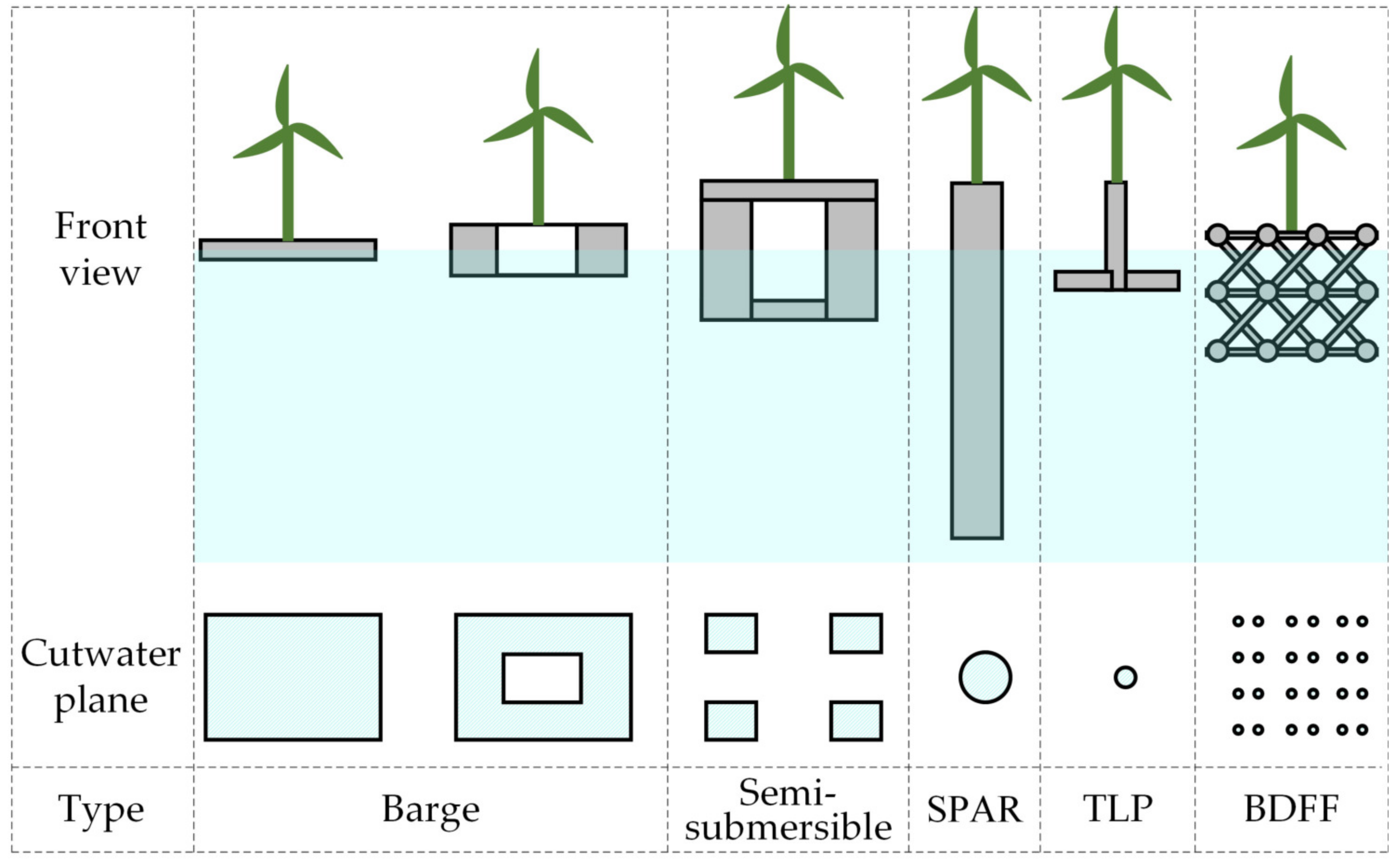
Figure 1. The area of cut-water plane varying with floating types without showing mooring lines.
Jmse 10 00292 g001
Figure 2. Sketch of the BDFF consisting of mid-floaters and com-floaters.
Jmse 10 00292 g002
Figure 3. Details of the mid-floater and the com-floater.
Jmse 10 00292 g003
Figure 4. Sketch of the floating system.
Jmse 10 00292 g004
Figure 5. The numerical computation progress of wave forces.
Jmse 10 00292 g005
Figure 6. The numerical computation progress of motion responses.
Jmse 10 00292 g006
Figure 7. Visualization of the interaction between the BDFF and waves.
Jmse 10 00292 g007
Figure 8. The comparison of steady drift between near-field and far-field method.
Jmse 10 00292 g008
Figure 9. 3D surface plot between the RAOs and the two interacted variables of wave frequencies and wave directions. (a) For pitch RAOs; (b) For heave RAOs.
Jmse 10 00292 g009
Figure 10. 3D surface plot between the RAOs and the two interacted variables of wave frequencies and wave directions. (a) For surge RAOs; (b) For sway RAOs.
Jmse 10 00292 g010
Figure 11. (a) Sketch of the wave basin. (b) The test model moored in still water. (c) The test model moored in waves. (d) The connection between the truss deck and the floaters. (e) The model dimension and the mooring arrangement.
Jmse 10 00292 g011
Figure 12. Pitch RAOs comparison between the simulation, experiments and a classical SPAR.
Jmse 10 00292 g012
Figure 13. Surge and heave RAOs comparison between the simulation and experiments.
Jmse 10 00292 g013
Figure 14. (a) The added mass A 31 , A 32 , A 34 , A 35 , A 36 ; (b) The added mass A 33 .
Jmse 10 00292 g014
Figure 15. (a) The radiation damping coefficient B 31 , B 32 , B 34 , B 35 , B 36 ; (b) The radiation damping coefficient B 33 .
Jmse 10 00292 g015
Table 1. Conceptions of different types of floating foundations.
StabilizedConceptionExample
TensionTLPBlueWater-TLP, Iberdrola TLPWIND, PelaStar
Diwets, GICON®-SOF
BallastSPARHywind, SWAY
BuoyancyBargeFloatgen, WindBarge
Semi-submersibleTri-floater, OC4-DeepCWind, Nautilus, WindFloat
W2Power, WindSea FLoater, Shimpuu, Tri-Floater
OO-Star, Sea-Reed, Sea Flower, TwinWind, WindFlo
Table 2. Main parameters of the floating system and mooring cables.
ParametersFloating System
System mass including ballast124.5 t
Diameter of spherical part of the floater, d 1 2 m
Diameter of cylindrical part of the floater, d 2 0.8 m
Centre-to-centre sphere spacing, L3.6 m
System draft depth3.1 m
Position of COG0, 0, −3.51 m
Moment of inertial, I x x , I y y , I z z 8425, 9036, 7490 t·m2
Number of mooring cables4
Mooring cable length, material75 m, anchor steel
Chain diameter of mooring cables, type0.03 m, studless
Cross-section axis stiffness of mooring cables7.6 × 10 7 N
Pretension of mooring cables10.5 × 10 3 N
Angle between mooring cables and the surge line30
Vertical depth of anchor points−50 m
Mooring anchor radius65 m
Vertical depth of fairlead points−11.8 m
Fairlead radius9 m
Table 3. The specifications of mesh convergence study for pitch motion.
Case123456
Max. mesh size, m0.070.10.120.150.250.5
No. of diffracted elements27,30126,20023,47415,36578503347
No. of total elements35,76934,79432,06823,83310,9115933
Relative error00.0080.020.050.090.26
Computation time, s245,232225,180209,988153,504103,39248,816
Publisher’s Note: MDPI stays neutral with regard to jurisdictional claims in published maps and institutional affiliations.