Review

Review and Future Perspective of Geophysical Methods Applied in Nearshore Site Characterization

1
Bachelor Degree Program in Ocean Engineering and Technology, National Taiwan Ocean University, Keelung 202301, Taiwan
2
Center of Excellence for Ocean Engineering, National Taiwan Ocean University, Keelung 202301, Taiwan
3
Department of Marine Environment and Engineering, National Sun Yat-sen University, Kaohsiung 804201, Taiwan
*
Author to whom correspondence should be addressed.
J. Mar. Sci. Eng. 2022, 10(3), 344; https://doi.org/10.3390/jmse10030344
Submission received: 12 January 2022 / Revised: 11 February 2022 / Accepted: 12 February 2022 / Published: 1 March 2022
(This article belongs to the Special Issue Recent Advances in Marine Geotechnics)

Abstract

:
Seabed surveying is the basis of engineering development in shallow waters. At present, geophysical survey methods mainly utilize sonars for qualitative surveying, which requires the calibration of the results found through in situ drilling and sampling. Among them, the parameters required for engineering designs are obtained from either in situ tests or laboratory experiments of soil samples retrieved from drilling. However, the experience from onshore applications shows that the physical quantities obtained through quantitative geophysical survey methods for shallow waters can be indirectly used to estimate engineering parameters or directly as parameters for engineering evaluation, which has high application potential. This review analyzes various geophysical survey methods for nearshore site characterization (i.e., side-scan sonar, single/multi- beam sonar, sub-bottom profiler, seismic reflection method, and underwater magnetometer) and challenges in their application, and introduces quantitative geophysical survey methods (including the underwater seismic refraction method, seismic surface wave method and underwater electrical resistivity tomography) that are worth focusing on for future development. Three application difficulties have been identified, namely, the lack of operational efficiency, appropriate operational equipment and systems, and sufficient guidance for experimental shallow sea applications. It is hoped that comprehensive discussion of these challenges will increase awareness leading to engineering improvements in the surveying and measuring capabilities in shallow waters, further reducing the risk of geotechnical hazards.

1. Introduction

In the past, human development moved from the plains into the mountains, yet with the demand for marine resources, this development is currently actively expanding to coastal and offshore areas. With the increasing reliance on the coastal and marine environment, more construction is being carried out, including the development of underwater foundations for existing bridges, sea tunnels or ports, as well as offshore wind farms, floating cities, and tidal stream generators, in an attempt to meet the needs for energy and living environments. Offshore wind power generation, in particular, is being developed for both the coastal and marine environment. Various infrastructure projects have been erected on the sea floor. Because of this, the surveying of the sea floor plays an important role, as it influences the selection of the project site as well as construction, operation, and maintenance details.
At the present stage of application, geophysical survey methods for shallow waters are mainly used in the planning stage to assist investigations; in addition to surveying seabed depth and landforms, it is an important application to determine the geological conditions under the seabed, using reflected waves from sonar signals, which determine material changes qualitatively and assist in evaluating the geologic structure with minimum drilling data. These common shallow water geophysical survey methods mainly provide interface information, but are unable to provide its engineering properties. However, many quantitative survey techniques can still be applied, such as underwater seismic refraction and electrical resistivity tomography [1]. These methods can provide the physical properties of materials beneath the seabed, which can be used to further derive their engineering properties, or can directly be the designing parameters. To help the engineering community improve the investigative capability in this area, this paper reviews various geophysical survey methods for shallow waters and evaluates the current challenges in their application. Based on the experience of land-based survey methods, quantitative geophysical survey methods for shallow waters that can be further developed in the future are identified, while their current state of development is reviewed and analyzed. It is hoped that the improvement of these technologies and the popularization of applications can enhance seabed surveying in shallow waters.

2. Geophysical Survey Methods and Engineering Survey Objectives

2.1. Geophysical Survey Methods

Geophysical survey methods are used to indirectly measure the properties of the subsurface layers of an area, including seismic, optical wave, direct-current, electromagnetic, and gravity methods. Engineering surveying involves many geophysical survey methods based on these physical fields, such as the seismic refraction method, surface wave method, and reflection method. Other examples include the electric resistivity tomography and induced polarization methods, which are derived from direct current injection. These techniques have different levels of applicability, depending on the purpose of the survey. They have their own characteristics and application limitations.
Geophysical survey methods provide different results after different analytic processes, sometimes, even when based on the same physical measurements. According to the properties of the provided results, geophysical survey methods can be roughly classified into three major categories, as shown in Figure 1. The first category is the physical value map, which includes the magnetic, electromagnetic, and self-potential methods. The main characteristic of this category is that it generally uses point-by-point measurements, that is, the measurement results do not need to be inverted, as the physical measurements can be obtained either directly, or after simple computation, and can be presented based on the location where the measurement is made, before evaluation. This result is mainly used to survey abnormal signals underneath the measurement area, and confirm the location of the target object (e.g., unknown buried objects underwater, metallic minerals, or abnormal leakage points). Under the premise of simplifying assumptions, one can roughly estimate either the volume of a target object (e.g., applying permeability in underwater surveys can provide the estimated size of an iron-hulled ship), or its depth [2]. However, since there are many influencing factors, it is still difficult to achieve this with unknown objects.
The results obtained in the second category of geophysical survey methods can identify the interface where the physical quantity changes; these methods include the use of side-scan sonar, single/multi-beam sonar, sub-bottom profiler, seismic reflection method, and ground-penetrating radar. These methods use elastic or electromagnetic waves for detection, with the data being recorded in a time series. Following the signal processing of the time series data, it is presented either as horizontal distance (side-scan sonar) or as a vertical section. The image will show the location of the surface with the change in physical quantity, detecting stratification or unknown objects in the seabed. The distance or depth of this surface needs to be converted using the elastic or electromagnetic wave velocity of the material; this velocity varies from substance to substance, and is usually obtained through hypothesis or physical measurement. However, since it is difficult to obtain measurements under certain conditions (e.g., in soil), the measurements are expressed in time without being converted to depth.
The third category consists of geophysical survey methods in which the physical quantities of the results are spatially distributed. This includes the seismic refraction, seismic surface wave, electric resistivity tomography, and induced polarization methods. After the physical data is collected, these methods use inversion technologies to obtain the physical values below the survey line. Since the physical values of the material in the layer as well as its location are considered in the inversion process, the physical values of different positions below the survey line and the depth of the target object can be provided.

2.2. Purpose of Engineering Surveying in Nearshore

Since the water depth in nearshore is usually shallow, the geophysical survey methods reviewed, herein, will mainly be based on waters with depths of less than 50 m, while primarily using depths of up to 20 m. This range includes the permanently submerged sea area, intertidal zones, wetlands, and fish farms that are influenced by tides. The aim of engineering surveying in shallow waters can be divided into two categories, namely, (1) above, and (2) below the seabed. Above the seabed, the main objective is to obtain the topography and landform of the seabed, while below the seabed, the main objective is to survey the stratification of the sub-bottom, the engineering properties of the materials, and any unknown buried objects, and ultimately to obtain the stratigraphic information required for the planning, design, construction, operation, and maintenance of a project. In recent years, the focus on underwater cultural heritage has increased, and unknown buried objects are no longer assumed to cause engineering risks such as unexploded bombs or abandoned fishing gear, but could also possibly be underwater cultural heritage [3].

2.3. Applications of Geophysical Survey Methods

To meet the engineering surveying aims mentioned above, geophysical and geotechnical survey methods are used together to obtain seabed information. Currently, the topography and landform above the seabed are mostly measured using side-scan and single- or multi-beam sonars, while sub-seabed measurements are conducted using sub-bottom profilers or seismic reflection method (depending on the depth) and magnetometers. However, sub-bottom profilers and seismic reflection mainly provide interface information on material changes and cannot provide the engineering properties of the seabed. Practically, they are obtained through geotechnical surveying methods such as drilling and sampling, or cone penetration tests. The geotechnical results at different locations are compared with geophysical surveying results for calibrating the engineering meaning of the interface. Then, the point data collected from the geotechnical survey are converted into 2D or even 3D data to help create a geological model of the field site.
When considering the above categories, the first and second geophysical survey methods are more commonly and routinely applied in nearshore engineering surveying, whereas the third category of methods to obtain physical measurements of materials is less common. However, many laboratory experiments have shown a clear correlation between these physical quantities and engineering parameters, which can be obtained indirectly from these physical quantities. For example, Lu and Liang [4] used laboratory experiments to investigate the S-wave velocity of the seabed in relation to its density and liquid limit, showing that the S-wave velocity of the seabed can be used to estimate the density and liquid limit; Gaiser [5] collected the P- and S-wave velocities of numerous seabed materials and calculated their Poisson’s ratio, and then proposed an empirical correlation between this ratio and seabed porosity. Further, Ayres and Theilen [6] used the empirical correlation between S-wave velocity and strength of the local seabed material to analyze the slope stability. Archie [7], Biella et al. [8], Klein and Santamarina [9], and others have suggested a highly linear relationship between formation factor (soil electric conductivity divided by the water electrical conductivity) and porosity; moreover, soil conductivity (the inverse of electrical resistivity) can be used to estimate hydraulic conductivity ([8,10]).
Based on these theoretical findings, an increasing number of cases have recently emerged in which shallow water geophysical methods of the third category have been applied in different engineering surveys: Punzo et al. [11] used the imaging profiles obtained from the underwater seismic refraction method to create a 3D model of harbor sediment and estimate its volume for use in further dredging planning. Caiti et al. [12], Park et al. [13], Ritzwoller and Levshin [14], Bohlen et al. [15], Puech et al. [16], Shtivelman [17], Park et al. [18], Kaufmann et al. [19], Hunter et al. [20], Boiero et al. [21], Paoletti et al. [22], and Long et al. [23] used the underwater seismic surface wave method to measure the S-wave velocity profiles of seabed sediments. Moreover, Johansen and Ruud [24] used the underwater seismic surface wave method on ice floes to find seabed properties in the arctic circle. Wilken et al. [25] used an underwater seismic surface wave method to survey S-wave velocity profile of the seabeds to allocate possible sites for offshore windtower installation, and subsequent dynamic analysis of monopile foundations.
Goto et al. [26] and Tartis et al. [27] used underwater electrical resistivity tomography to survey natural gas hydrates in the seabed. Passaro [28] and Simyrdanis et al. [29] used underwater electrical resistivity tomography to survey metal vessels buried under the seabed. Rucker et al. [30], Apostolopoulos [31], Okyar et al. [32], and Dahlin et al. [33] used underwater electrical resistivity tomography to survey seabed composition and understand the distribution of sediments, which was used as a reference for dredging planning. Apostolopoulos [31] used underwater electrical resistivity tomography to survey the location of the foundation of an older bridge under the seabed, which was used for bridge maintenance and renovation planning. Dahlid and Loke [34] used underwater electrical resistivity tomography to survey seabed composition for the design and planning of an undersea tunnel. Hermans and Paepen [35] combined land and marine electrical resistivity tomography data in the intertidal zone to survey seawater intrusion. Tassis et al. [36] used underwater electrical tomography to survey fracture zones in bedrocks. Papadopoulos et al. [37] applied underwater electrical tomography to investigate the prehistoric submerged site within ultra-shallow waters.
Mouton and Robert [38] used the underwater seismic refraction method and seismic surface wave method to classify sediment types within 10 m below the seabed, which was applied to the planning of a submarine pipeline. Ronczka et al. [39] used both underwater electrical resistivity tomography and underwater seismic refraction method to survey prominent fracture zones in nearshore bedrock. Kritikakis et al. [40] combined underwater electrical resistivity tomography, underwater seismic refraction method, and seismic surface waves to survey underwater ruins buried under the seabed in shallow waters.
All the successful cases above demonstrate that the quantitative geophysical methods have high potential in nearshore site characterization. In the following sections, to differentiate the existing and promising geophysical survey methods in category three, the commonly applied side-scan sonar, single- and multi-beam sonar, sub-bottom profiler, seismic reflection method and marine magnetic survey are categorized as common geophysical methods, and geophysical methods capable of obtaining physical quantities in category three are categorized as quantitative shallow water geophysical methods.

3. Common Geophysical Methods for Nearshore Site Characterization

3.1. Seismic Survey Methods Related to Changes in Physical Quantities

In the application of engineering surveying in nearshore, the common geophysical methods belong mainly to categories one and two in Figure 1. In these two categories, several methods are based on electromagnetic waves. However, due to the influence of the high conductivity of seawater, the energy of electromagnetic signals attenuates strongly in seawater. Consequently, the electromagnetic wave-based methods are not often applied, and the popular methods are based on longitudinal waves (sound waves), which are less affected by seawater. These methods include the use of a side-scan sonar, single-beam sonar, sub-bottom profiler, and the seismic reflection method.
These methods use the reflected waves generated by the acoustic waves as their detection signal [41]. When an artificial vibration is generated in the water, it is affected by the inability of water to propagate shear waves, hence the vibration is instead transmitted as a longitudinal wave. Once this wave encounters a difference in the acoustic impedance of the material, it will become reflective and transmissive, and this behavior will follow Snell’s Law. The reflected/backscattered signal, which is used to analyze the information of the target layer, then propagates back and is picked up by a hydrophone. Here, the acoustic impedance is the product of the density of the material and the velocity of the longitudinal wave. The density of the geological material usually has little variation, meaning that the acoustic impedance is mainly determined by the material’s longitudinal velocity. However, if non-geological materials such as metals are encountered, their density also plays an important role.
These techniques, which are mainly based on reflected waves, make the distance between the vibration source and the hydrophone smaller. The time T is the time required for the wave to travel the distance (2× D) from the vibration source to the interface of the material change and then back to the vibration source, which is known as the two-way travel time. If the material’s longitudinal velocity Vp is already known, the interface depth D of the material change is located at T/(2Vp) below the vibration source.
The principles of these methods are the same. However, due to the difference in the frequency of the vibration sources used, they can be applied to different surveying purposes. The energy attenuation of longitudinal waves transmitted in water is extremely low, but when it enters the seabed, the attenuation will greatly increase. The soil type of the seabed and the frequency of the longitudinal waves are the main factors affecting energy attenuation in the seabed. In terms of soil type, the energy attenuation of longitudinal waves in the seabed is greater in sandy or compact sediments than that in clay or loose sediments and, in terms of frequency, the energy attenuation of high-frequency longitudinal waves is greater than that of low-frequency longitudinal waves [42]. Additionally, the detection accuracy of these longitudinal waves is affected by their wavelength (longitudinal wave speed/frequency): the shorter the wavelength (with high frequency), the higher the resolution, and vice versa. From this, it can be understood that high-frequency waves have a good resolution but a poor ability to penetrate the seabed, while low-frequency waves have a great ability to penetrate the seabed but a low resolution. Based on these features, the following four subsections will introduce each survey method.

3.1.1. Side-Scan Sonar

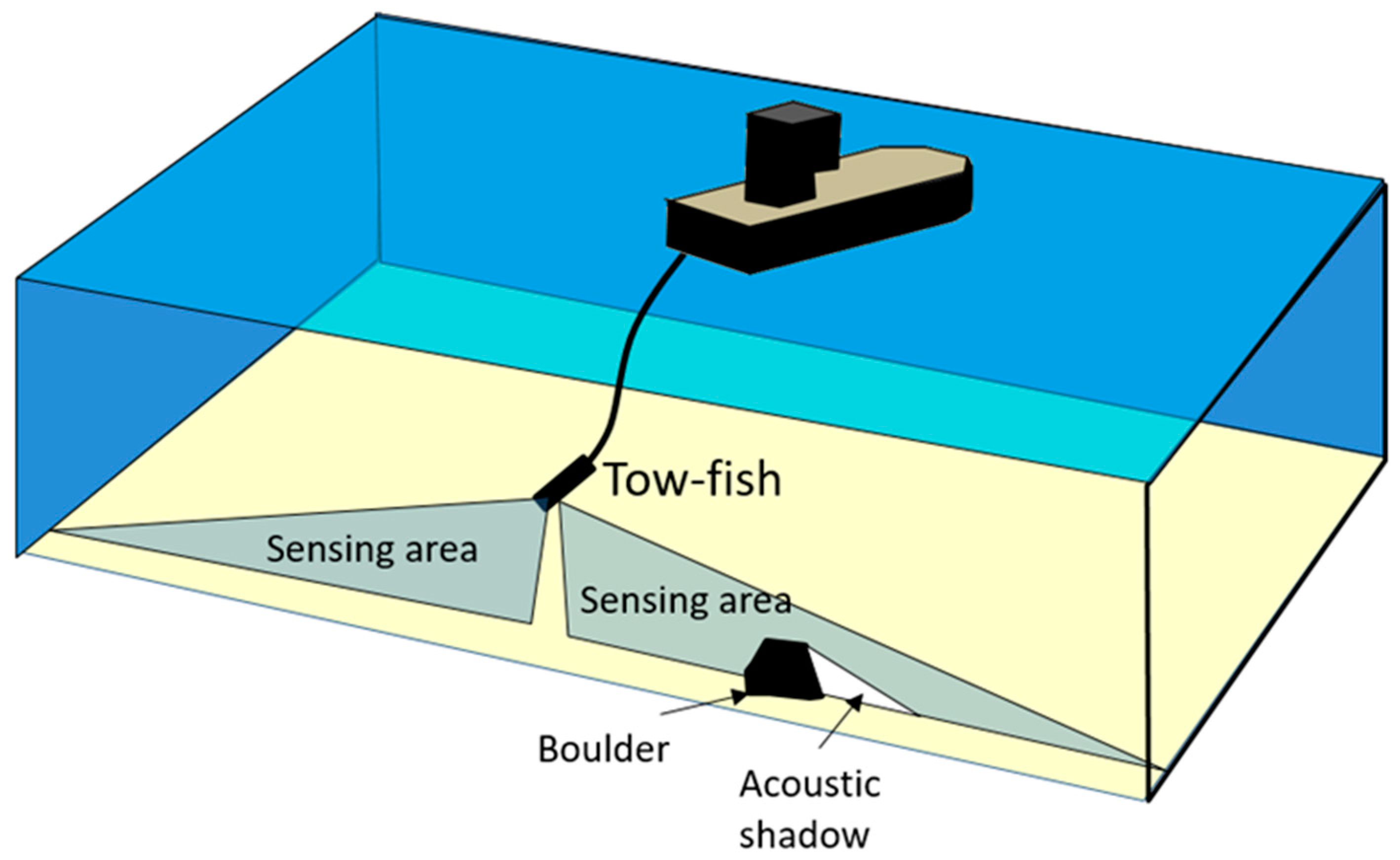
The side-scan sonar is mainly used for geomorphology surveys of the seabed, and its results can provide photo-like details of the seabed surface. The sonar generates underwater vibrations. Mostly, the center frequency of the vibration would be between 100–900 kHz, which is the highest frequency used in reflected-wave-based survey. This frequency, provides a high resolution, but little penetration. During the surveying (as shown in Figure 2), a boat towed the tow-fish, where the sonar was installed in port and starboard; in order to reduce its unstable movement during the surveying, stabilizing fins were installed in the tow-fish [1].
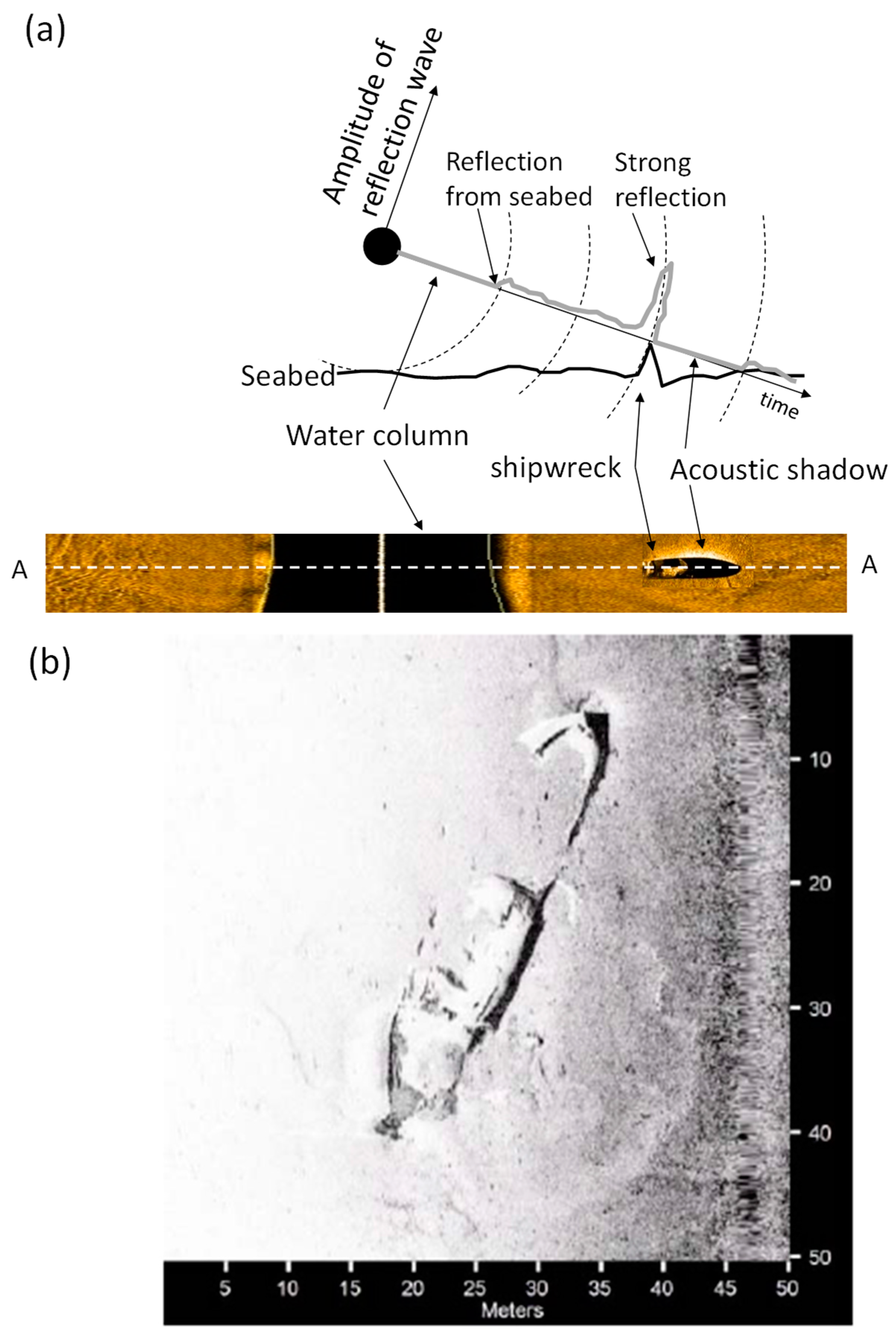
When surveying, the acoustic wave is emitted diagonally downward at a small angle toward the seabed; the signal (shown in Figure 2) is fan-shaped, covering more than a single direction. Since the angle between the emitted waves and the seabed surface is relatively small, the travel distance can be converted to a horizontal distance, and since there is almost no seabed penetration under such a high frequency signal, it is certain that all reflected signals originate from or above the seafloor within the sonar range. Following the recording, the intensity of the received backscattered signals is color-coded, and the obtained data is shown in Figure 3a. Initially, before the wave meets the seabed, there is no backscattered energy from the signal. The blind spot, marked in black in the figure, is the result of the distance between the side-scan sonar and the seabed. When the signal meets the seabed, it will start to maintain a certain level of backscattered energy, which varies slightly depending on changes in elevation, roughness of seafloor, and material composition of the seabed. When there is a significant change in seabed conditions, or when other objects are present on the seabed, the backscattered energy becomes much greater. As the detected object protrudes from the surrounding seabed, the seabed surface behind the location will be obscured. This presents a similar effect as when a flashlight shines outward, a shadow will appear behind any object put in front of the light, producing a shaded area without reflection on the recorded image, which will revert to normal after a certain distance.
For each measurement, images of the seabed surface from both sides of the survey path are obtained, allowing the recorded reflected signals to be presented in a continuous sequence of images. Although it is technologically possible to use image stitching to present the products of side-scan sonar as one whole image, when it comes to actual interpretation, image sequences are still used to clearly identify the seabed topography and possible target objects (as shown in Figure 3b). Furthermore, in addition to being able to detect target objects, the length of the shaded area in an image sequence allows the height of the target object to be estimated.

3.1.2. Single- and Multi-Beam Sonar

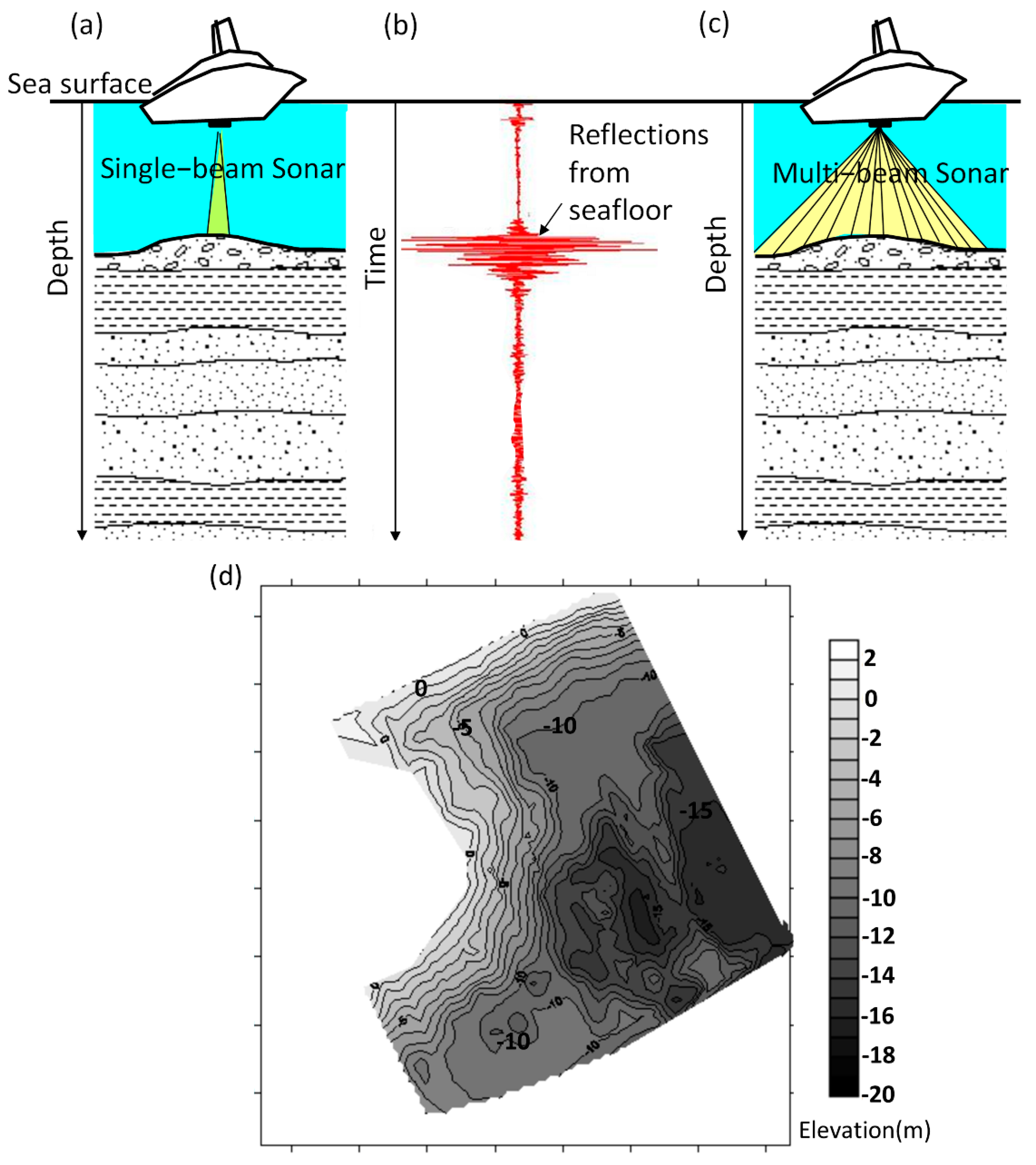
Compared with the side-scan sonar, which transmits its signal at a small angle to the seabed, when using a single- or multi-beam sonar, the signal is transmitted to the seabed surface in a near-vertical manner. For surveying, the commonly used frequency is 10–400 kHz, depending on the required depth and resolution. The earliest form of sonar surveying, which can be seen in Figure 4a, uses a single beam and is known as a single-beam sonar. Its frequency does not allow for effective penetration of the seabed. Its signal will be reflected from the seabed and received by the hydrophone close to the sonar (Figure 4b). Through analysis of the signal, the sonar’s software records the time of received reflected signals from the seabed (i.e., two-way travel time), after which the longitudinal wave velocity is used to calculate the seabed depth. To ensure greater accuracy of the survey results, the sonar is normally fixed on the hull of the surveying vessel, and the final results are obtained by combining a satellite positioning system, motion reference units, gyro compass (which accounts for swaying caused by waves) on the vessel, and tide gauge (which converts water depth into an elevation value) nearby.
It is worth mentioning three characteristics of the sonar. First, the signal emitted from the sonar is concentrated in a small angle (called beam angle, usually in the order from 5–20 degrees, depending on the instrument). Since the emitted wave is a cone-shaped beam, the received signal is reflected from an area on the seafloor, called a footprint. As the depth increases, the footprint becomes larger. For example, if the angle of the signal is nine degrees, at a depth of 10 m, the signal’s footprint forms a circle 1.57 m in diameter. At a depth of 20 m, this circle will thus be 3.15 m in diameter. Therefore, as the water depth increases, the horizontal resolution of the seabed elevation will decrease. Second, different frequencies of emitted waves have different levels of penetrating depth. When using different frequencies to survey a seabed with a higher proportion of fine-grained sediments, the signal will be affected by the suspension sediments, resulting in differences in the obtained water depths. Third, since the water depth is obtained by converting the longitudinal wave velocity, and the longitudinal velocity in shallow waters does not vary much with depth, the average value is generally around 1500 m/s. However, in special cases, such as turbid water with a large amount of suspension sediments, the difference in longitudinal wave velocity may be greater, making the depth conversion less accurate. In such cases, a better approach to obtain more accurate depth results would be to measure the seawater velocity of the surveying area. When interpreting the results and planning a project, these effects should be taken into consideration.
In recent years, with advances in technology, the multi-beam sonar has been developed. It combines several single beam sonars, each transmitting a signal with a small beam angle, creating a combined detection range of more or less 160 degrees, as can be seen in Figure 4c. This allows the sonar to survey a larger area in a single session, increasing seabed-detection efficiency, and has become the mainstream technology for bathymetry survey recently [43,44]. However, since some of the beams are emitted from a larger angle, sonar clutter creates interference problems. Thus, in very shallow waters (water depth < 10 m), its application is not ideal, and single-beam sonars are still preferred. As the sonar only retains the depth and location of the seabed surface, the data obtained are points from different spatial locations forming a point cloud. These point clouds can be visualized by using colors to indicate elevation/depth (see Figure 4d), or simply by using contour maps.

3.1.3. Sub-Bottom Profiler

A sub-bottom profiler (due to the complexity of signal processing, this review considers a sub-bottom profiler to be the use of a single hydrophone for signal recording, and the use of multiple hydrophones for signal recording to be the marine seismic reflection method) is mainly used to survey the sub-seabed soil structure or buried materials. Because of this, a lower frequency wave which has larger penetrating depth is used, usually ranging between 500 Hz and 40 kHz. To meet this frequency range, a more diverse range of vibration sources is used, depending on the required depth and resolution. The most commonly used sources are as follows [1]:
  • Pingers: single frequency, generally between 3.5–15 kHz; can survey a seabed up to 50 m deep; resolution of about 0.3 m;
  • CHIRP: Uses a wide range of frequencies, generally between 3–40 kHz; can survey a seabed up to 50 m deep; resolution of about 0.3 m;
  • Boomer: Frequency generally between 500 Hz and 5 kHz; can survey a seabed up to 30–100 m deep; resolution between 0.3–1 m;
  • Sparkers: Frequency generally between 0.05–4 kHz; can survey a seabed up to 1000 m deep; resolution between 0.3–3 m.
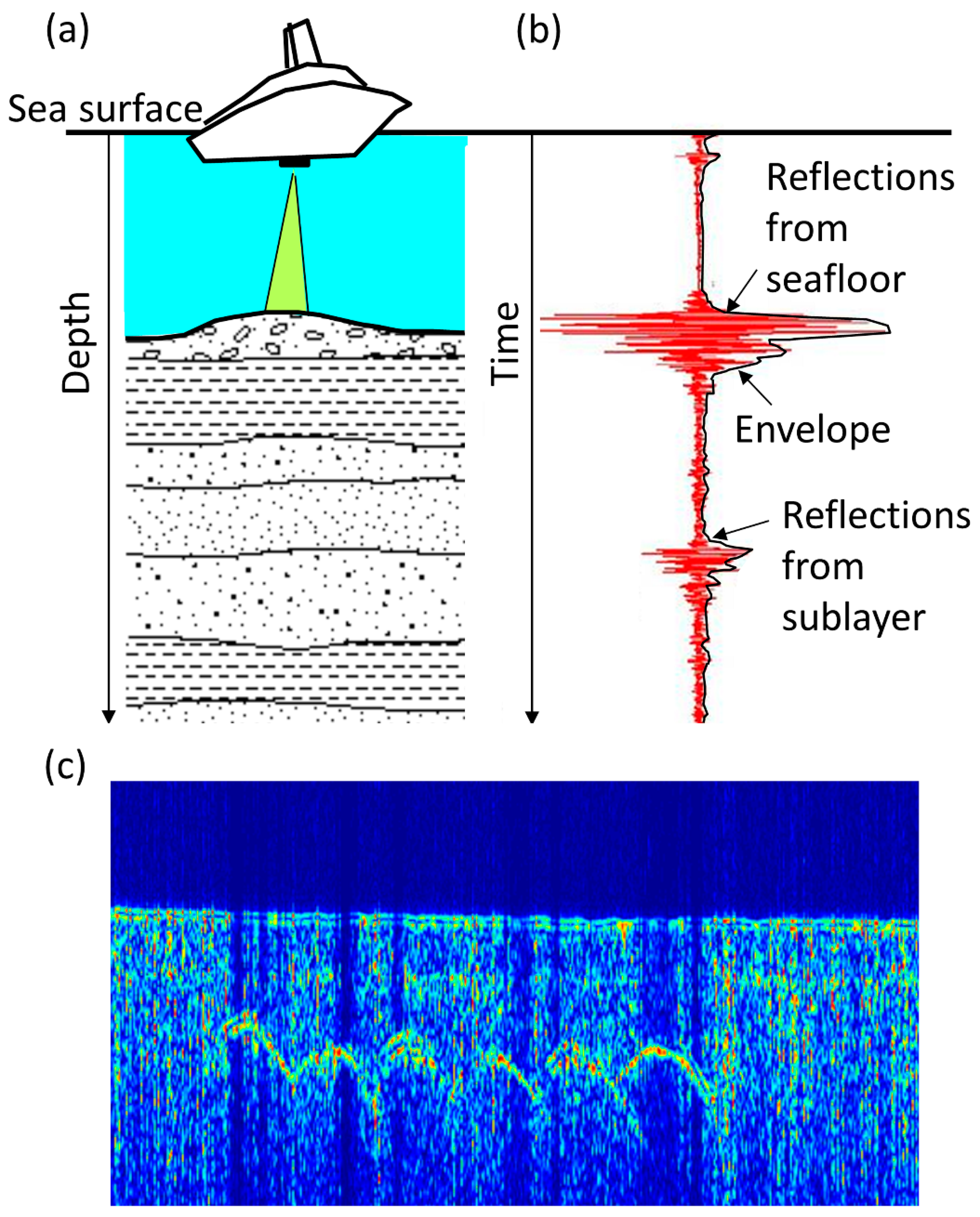
The sub-bottom profiler is similar to the single-beam sonar in that the source of vibration and the hydrophone are ideally placed at almost the same location to obtain a better reflected signal; when it comes to measuring depth, the main difference with the single-beam sonar is in the lower sound frequency. In a survey using an electroacoustic transducer or a CHIRP sonar as its source of vibration, the device can either be attached to the hull of the survey vessel (see Figure 5a) or towed behind the vessel. When using a boomer or a sparker, the larger size of these vibration sources means that they generally need to be towed behind the survey vessel. The hydrophone is placed as close as possible, and is towed behind the vessel to collect data.
From these sources of vibration, the longitudinal wave signal will be reflected back to the hydrophone after touching the seabed surface, while at the same time, the longitudinal wave will continue to pass down into the seabed until it touches another interface with a significantly different acoustic impedance, reflecting back to the hydrophone once more (see Figure 5b). This penetrating nature allows it to obtain information about the strata or buried objects below the seabed. The recorded signal is presented as an image; however, an envelope is first computed using the Hilbert transform (see Figure 5b). Then, the values of the envelope are color-coded to obtain the vertical image (see Figure 5c) below the survey line. This image can then be used to identify possible stratification or signs of buried objects.

3.1.4. Marine Seismic Reflection Method

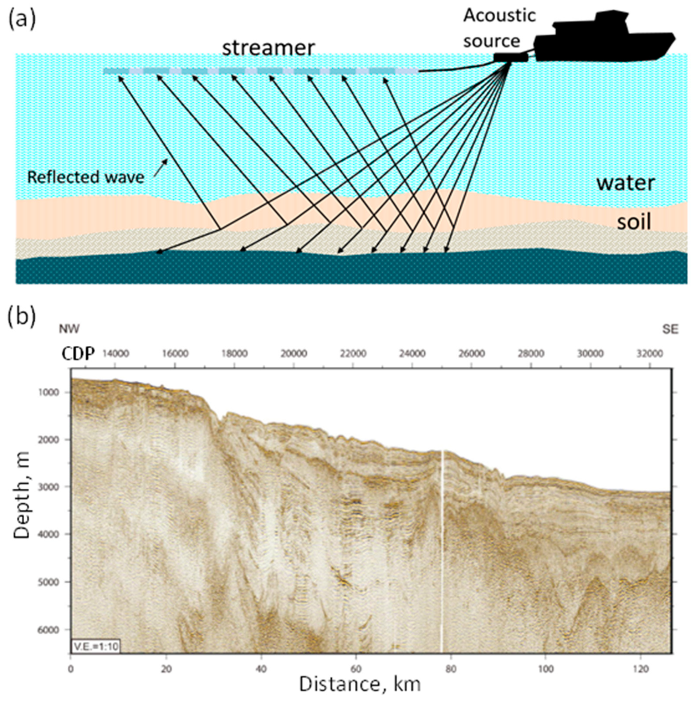
When using the marine seismic reflection method in shallow waters, the focus is on surveying the soil structure at a deeper depth. A boomer or a sparker would be the main source of vibration. As shown in Figure 6a, the source of vibration is towed behind the survey vessel, followed by a series of hydrophones (called a streamer) recording the reflected waves. During the recording, the source continues to emit vibrations at set intervals, and the signal generated by each shot is recorded and stored.
Since multi-channel receivers are used for data recording, a more complex signal processing method can be used to improve data quality. First, it is necessary to locate the position of the data that generate the vibration and receive signals at different locations. Then, after determining the position of each shot and its corresponding receiver, a set of signals with the same shot point, and whose receivers have the same midpoint, are collected; this is known as the Common Depth Point (CDP). Finally, to carry out sequence analysis of CDP data, which includes predictive deconvolution, multiple suppression, velocity analysis, and normal moveout correction, the data are stacked to obtain the reflected signal data of the CDP. All the processed data are gathered according to the CDP position, and the data are then further proceeded with F-X deconvolution and migration [45]. After the complex signal processing, the gathered seismogram is presented as shown in Figure 6b. Different to the sub-bottom profiler data, the envelope of the signal is usually not calculated when the processed vibration signal is presented. Instead, the vibration signal is presented directly. Finally, these results are used for stratigraphic interpretation.

3.2. Underwater Magnetometer

The underwater magnetometer is a method used to survey the horizontal distribution of an anomaly in magnetic force on or below the seabed surface. During engineering surveying, it can mainly help in examining the horizontal position of semi-buried or buried objects containing ferromagnetic material underwater. Ferromagnetic material usually includes materials containing iron or steel. The underwater magnetometer needs to be towed behind the survey vessel and as close to the seabed as possible. If the survey vessel is an iron/steel vessel, the underwater magnetometer is usually towed at least 2.5-fold the vessel length behind, to reduce the influence of the vessel itself on the measurement results [46,47].
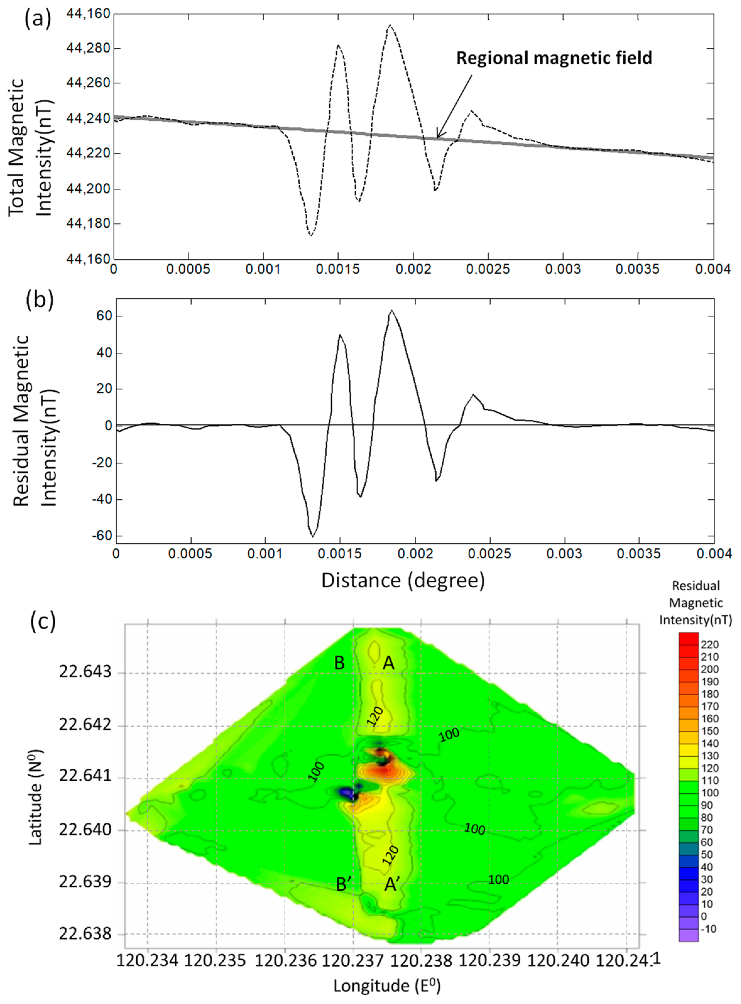
The underwater magnetometer survey results are shown in Figure 7a, which shows the distribution of the measured location and magnetic force (the figure shows the measured time in sequence, and has not been redrawn in accordance with spatial location). In this data, the magnetic intensity is the sum of the earth’s magnetic field, the induced magnetic field of the regional geology, and anomalies caused by the target object. Although the magnetic signal created by the target object usually has a higher frequency, the magnetic disturbance caused by the target object is small and difficult to identify if the signal has not been separated from the total magnetic field. As a result, it is usually necessary to deduct the regional magnetic field intensity before presenting the results. After graphing the residual magnetic intensity according to its horizontal spatial position, a contour plot can be created by color-coding the intensity (see Figure 7c). From this image, the locations of anomalies can be interpreted. When interpreting the magnetic anomalies of man-made objects such as iron/steel ship or aircraft wreckages, positive and negative values usually appear next to each other, resulting from the dipole character of the object induced magnetic field.

3.3. Challenges in the Application of Common Shallow Water Geophysical Methods

The common geophysical methods for shallow waters are mainly conducted by towing a survey instrument behind a vessel or by fixing it on the vessel. As such, when data are collected, the survey vessel simply needs to reduce its speed rather than stopping, making it highly efficient. However, there are still difficulties in the application of current survey methods. According to the author’s experience, it can be divided into three main categories:

3.3.1. Difficulties in Surveying Very Shallow Waters (Water Depth < 5 m)

All common geophysical survey methods suffer from this problem. First, in the case of underwater magnetometers, a suitable vessel for surveying in very shallow waters needs to be found. Second, it is difficult to collect data when towing an instrument in shallow waters, as there is a risk of the instrument hitting the bottom or getting entangled in discarding fishing gear and other objects. In addition to finding a suitable vessel, when the survey method uses a source of vibration, another issue arises. Due to the small distance between the seabed and surface, when the survey is conducted, the reflected waves, returning after the longitudinal waves touch the seabed, will be transmitted downward again. This means that multiple reflected signals that detect the same interface will continuously appear at very similar times, thereby interfering with the target signal. In addition, in these shallow waters, waves and coastal currents cause severe interference. Consequently, even if multiple reflections from the sea surface can be avoided, it is difficult to obtain clear images from side-scan sonar surveys since they require a stable flow field [49,50,51].

3.3.2. Limited Information Acquired below the Seafloor

The use of an underwater magnetometer for the surveying of semi-buried or buried objects is only effective when it comes to materials with magnetic susceptibilities. Further, as it is difficult to identify the unknown object’s depth or size, this method cannot provide complete information of the object below the seafloor. The use of a sub-bottom profiler requires a sufficiently different change in the acoustic impedance of the material for detection to be possible, meaning that gradual changes in materials below the seabed might not be captured. In addition, as can be seen in Figure 4b and Figure 5b, the longitudinal wave signal used for surveying has a specific frequency, meaning that it requires a certain amount of time for the reflected signal from an interface to end. If the reflected signal from the next interface or the bottom of a buried object appears before the end of the prior signal, detecting the presence of this interface becomes difficult or impossible. Similarly, if the buried object is below and close to the seabed surface, the multiple reflections between the surface of the object and seabed surface will make the surveying impossible, as the bottom profiler can detect the existence of the buried object but cannot determine its possible vertical size.

3.3.3. Inability to Obtain Material Properties of the Seabed

Regardless of whether a survey uses a magnetometer or a sub-bottom profiler, it is very difficult to obtain the material properties of the seabed from the results. Although there are already studies using a side-scan sonar [52], multi-beam sonar [53], and sub-bottom profiler [54] to obtain the average properties of the seabed surface at a certain depth, these methods require a complicated calibration process and are affected by the stability of the vibration source, making it difficult to obtain data on material change at different depths.
These three challenges regarding the application of common geophysical survey methods for shallow water require further development and improvement. Among them, the limited information acquired from surveying below the seafloor and the inability to obtain material properties from the seabed can be improved through quantitative geophysical methods for nearshore site characterization, which will be introduced in Section 4.

4. Quantitative Geophysical Methods for Shallow Waters

The third category of quantitative geophysical methods for shallow waters includes several methods. By adjusting the measurement equipment, the techniques applied onshore can be applied to shallow waters, including the underwater seismic refraction method (USRM), the underwater seismic surface wave method (USSWM), underwater electrical resistivity tomography (UERT), and the underwater-induced polarization method. The underwater-induced polarization method, as is used in obtaining the polarization properties of a material, which is relative to the electrical capacitance, is suitable for surveying subseafloor minerals, disseminated sulfide deposits, or marine pollution [55]. The others, USR, USSW and UERT, are valuable for engineering surveying, as has been mentioned in Section 2.3. However, based on their land-based applications, their potential is still highly underestimated.
Research on land-based applications shows that, in addition to being used for engineering surveying, these methods can also be tools for engineering inspection and quality control. For example, the seismic refraction method and electrical resistivity tomography have been frequently applied in the surveying of unstable strata [56]. Additionally, Lin et al. [57] applied the three techniques for safety inspections of dams in Taiwan, while Kim and Park [58] used the results of the seismic surface wave method to measure the density of a field after dynamic compaction, in order to evaluate its effectiveness. Lin et al. [59] used the S-wave velocity obtained through the seismic surface wave method for the assessment of seismic-induced liquefaction potential of soil. Fratta et al. [60] combined longitudinal wave velocity with time-domain reflectometer measurements for rapid detection of in situ density. Madun et al. [61] applied the seismic surface wave method to examine the effectiveness of stone columns on ground improvement. Lin et al. [62] used the seismic surface wave method to examine the overall improvement rate by looking at the difference in S-wave velocity measured before and after jet grouting for site improvement. Lin et al. [63] used electrical resistivity tomography to examine the pile diameter and completeness of soilcrete columns. The engineering problems tackled in land-based case studies such as the investigation of unstable strata, soil improvement effectiveness testing, soil liquefaction due to earthquakes, and safety inspection of dams, are also important and needed in nearshore engineering, showing that quantitative geophysical methods for shallow waters have not been fully explored in engineering operations, and possess high potential for development.

4.1. Underwater Seismic Refraction Method (USRM)

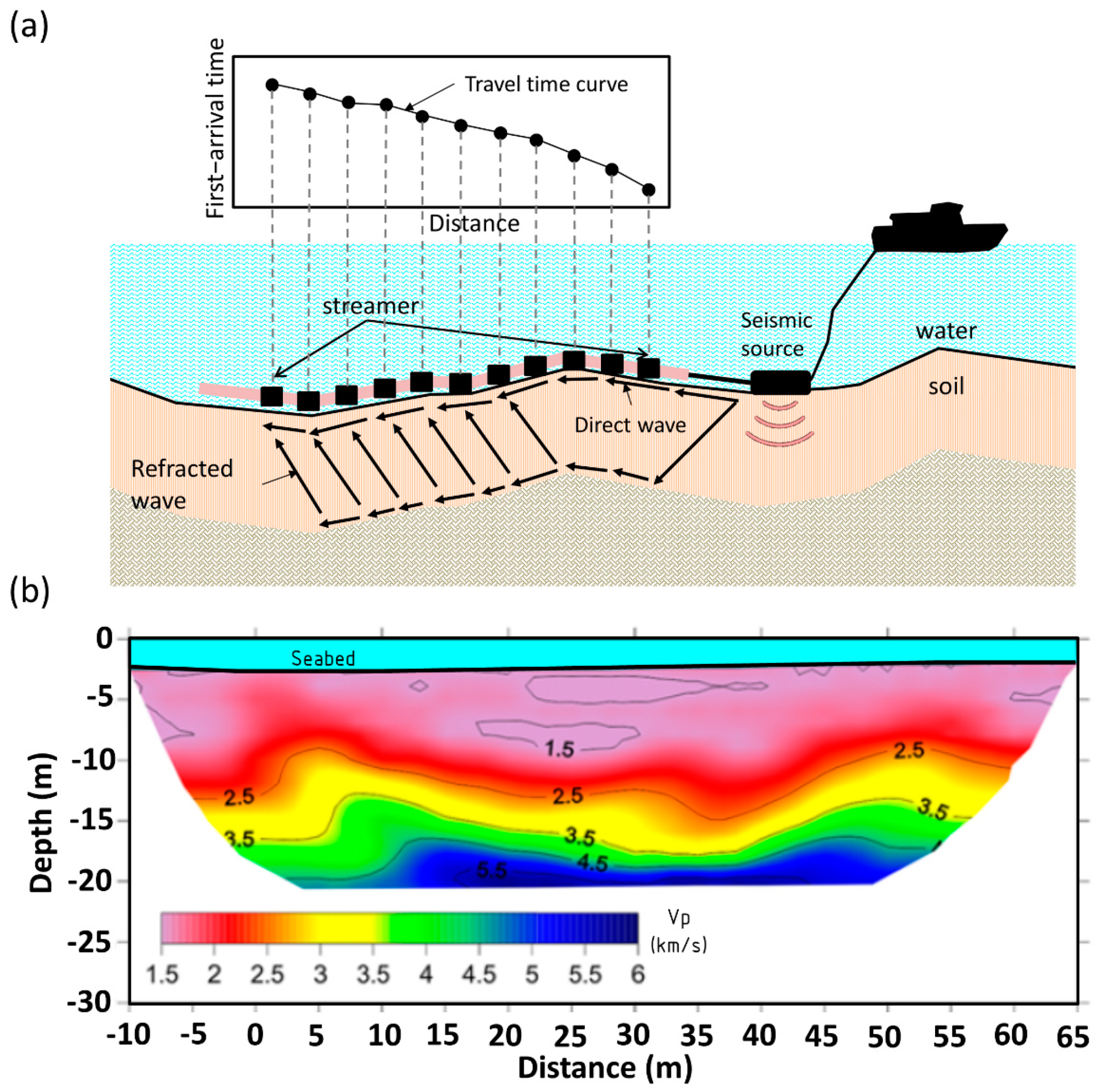
The underwater seismic refraction method generates artificial shock waves, which are transmitted to the submerged strata. Due to the difference in velocity between strata, the shock waves are reflected in each layer in accordance with Snell’s law. Once the incident angle is large enough, the reflected wave will follow the interface to propagate. This will generate a refraction wave and return to the surface. There, the waves are received by a geophone or hydrophone, positioned either on the surface or in the water. The refraction waves are easily identified, as they are the first signals to arrive at the receiver (as shown in Figure 8a). The collected first-arrival times at different locations is called the travel-time curve, allowing for the structure of the stratum to be found.
To make the number of travel-time curves large enough to conduct two-dimensional stratigraphic analysis, it is necessary to distribute multiple shot points evenly inside and outside the survey line. Usually, there will be 5–7 shot points inside the survey line, and one shot point on each side outside the survey line. The first-arrival time would be picked for each shot to create a travel-time curve. After which, the travel-time tomography is applied to back-calculate the two-dimensional velocity profile. As shown in Figure 8b, the velocity distribution of soils below the seafloor is usually expressed using different colors. This velocity is generally the longitudinal wave velocity (P-wave velocity, or Vp), but can also be the shear wave velocity (S-wave velocity, or Vs) when specialized vibration sources are used.

4.2. Underwater Seismic Surface Wave Method (USSWM)

When a source generates vibrations in the water or on the seabed surface, in addition to generating longitudinal waves and shear waves, interface waves are created at the interface between the water and the soil. These interface waves in the vertical direction generally come in two forms, one being Scholte waves, and the other being Leaky Rayleigh waves. Leaky Rayleigh waves occur mainly on the seabed surface when the shear wave velocity of the shallow depth of seabed is greater than the longitudinal velocity of the water [24]. Due to this, in most non-rocky shores, only Scholte waves exist.
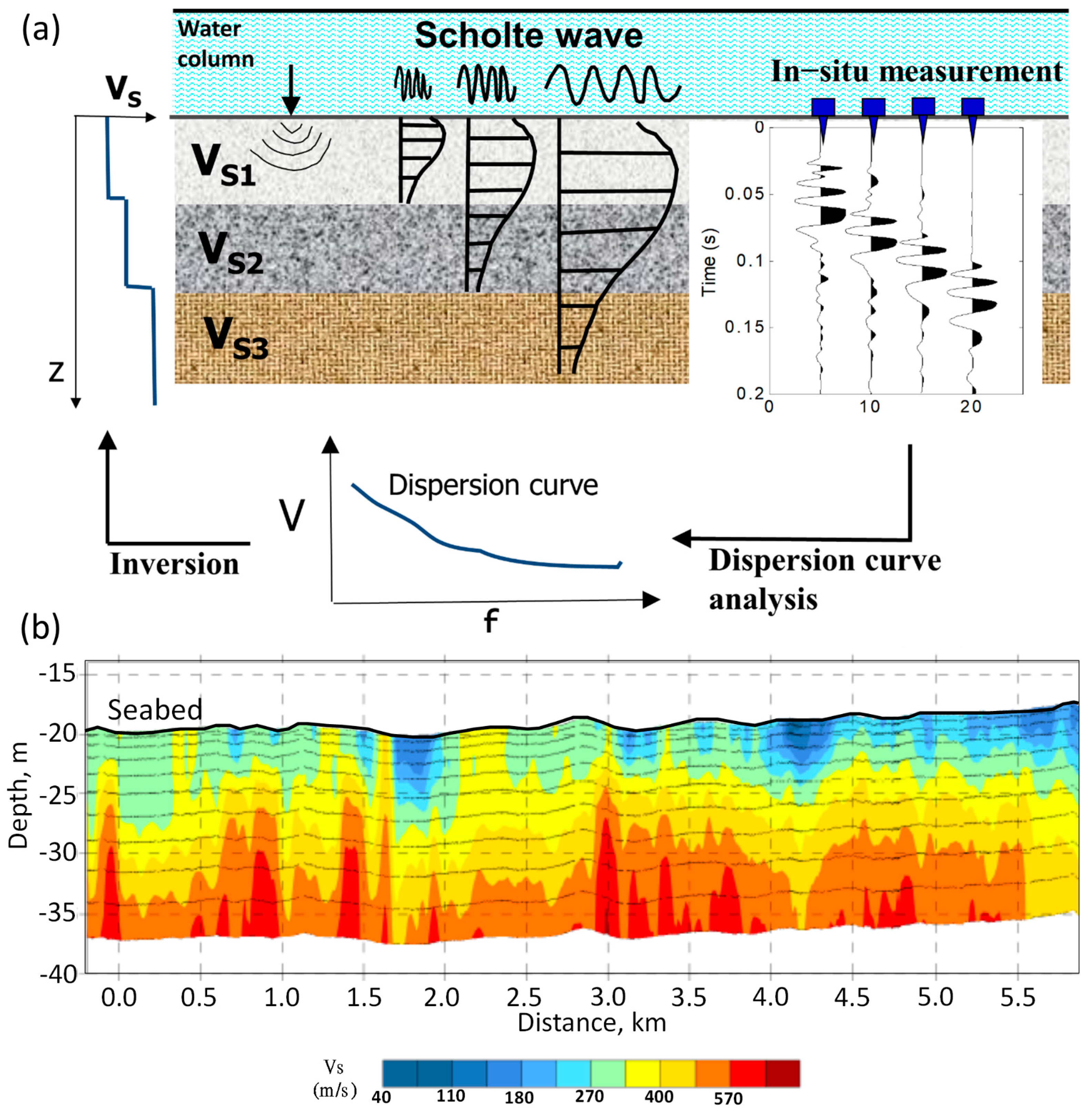
Scholte waves are the underwater surface waves mentioned in this review. They propagate along the seabed surface, and their sampling volume in depth is limited to approximately the depth of one wavelength. Because of this, the sampling depth of underwater surface waves depends on the wavelength. As the shear modulus (function of shear wave velocity) of a soil layer varies with depth, the phase velocity of surface waves at different wavelength will change. This is called the dispersion phenomenon. The relationship between the wavelength (frequency) and the phase velocity within this phenomenon is called the dispersion curve, which is primarily driven by the shear wave velocity of the stratum and, therefore, is less sensitive to the longitudinal velocity and density of the soil layer. The process of underwater surface wave analysis is shown in Figure 9a. After the signal recorded by hydrophones or geophones, the phase velocity of surface waves at different frequencies can be obtained by dispersion curve analysis. Subsequently, the shear wave velocity of the layered structure is inverted, based on layered model assumption. Each measurement can obtain a one-dimensional shear wave velocity profile. In practice, the velocity is represented by the halfway point of the survey line. By continuously moving the location of the survey line, all the collected 1D shear wave velocity profiles at different locations can be converted into a two-dimensional image, as can be seen in Figure 9b.

4.3. Underwater Electrical Resistivity Tomography (UERT)

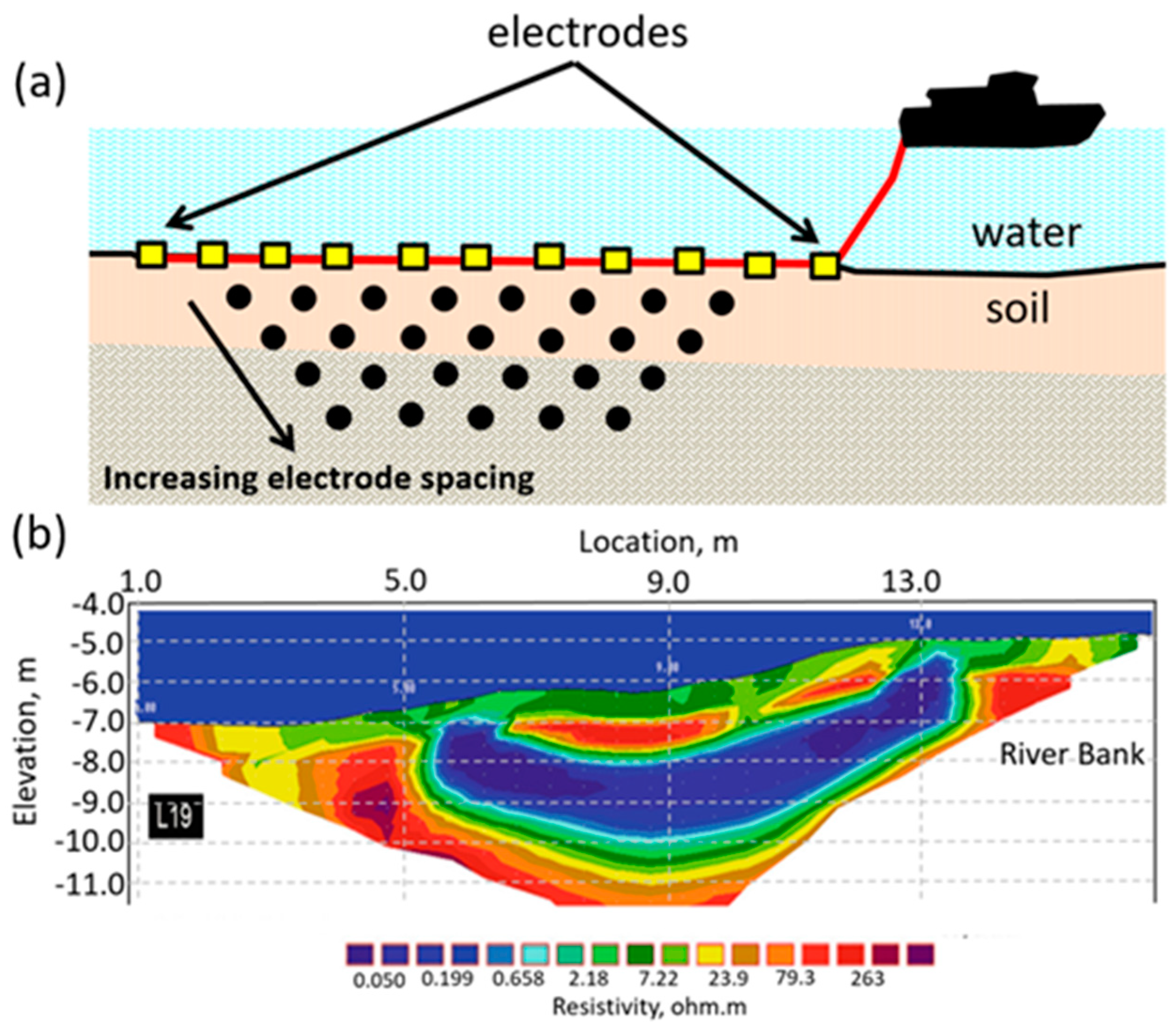
The surveying principle of underwater electrical resistivity tomography is based on the injection of low-frequency electric currents into the seabed through two electrodes at different locations, after which, the voltage difference at another two locations is measured by electrodes. Each measurement is made in a group of four electrodes. Following the measurement, the voltage and current values are used to calculate the apparent resistivity of the tested layer using the electrostatic theory. The effective depth of the apparent resistivity is dependent on the distance between the electrodes (see Figure 10a). During the measurement process, the electrodes are switched and the spacing is altered to obtain apparent resistivity data at different locations and depths of influence (with the advance of technology, nowadays, the data are obtained through automated switching sequencing of electrodes at different spacing and locations). The data are often expressed as a two-dimensional pseudo-section, and the two-dimensional resistivity profile distribution can be inverted from these data using tomography techniques (see Figure 10b).

4.4. Challenges in the Application of Quantitative Geophysical Methods for Nearshore Site Characterization and Future Development Directions

As reviewed above, quantitative geophysical methods have high potential to be applied in nearshore site characterization and in solving engineering problems. However, as difficulties in the application of these geophysical methods exist, they are still not widely used for surveying shallow waters. The three main difficulties are as follows:
1: Shortcomings in operational efficiency
Quantitative geophysical methods for nearshore site characterizations require high-density data to invert the physical quantities of materials, and usually require multi-channel equipment. The operation of these geophysical methods can be divided into three categories: boat tow, deep tow, and settle down on seabed. The boat tow and deep tow methods allow for continuous data collection, which makes the surveying efficient. However, they need to discard some information to earn the efficiency. For example, the boat tow UERT measures the seawater column and seabed simultaneously. Seawater as the intermediate medium, with very low electrical resistivity, reduces the sensitivity of the seabed measurement. Further, the rate of the data acquisition needs to be considered for continuous measurement. A better practice for collecting UERT data is switching the measurement electrodes at different locations. However, in order to meet the rate of data acquisition, the data collection intensity must be reduced, which affects the resolution and reliability of the results.
The deep tow method can reduce the impact of seawater. Continuously towing a long series of sensors close to the seabed surface to collect data means it can easily hit or get entangled in protrusions, causing damage to the equipment. Therefore, stationary measurement is more desirable than deep tow measurement if the resolution and reliability are required in engineering applications. However, more working time is not the only effort needed to be offered in stationary measurement. The directional change in tidal current is usually significant in nearshore areas. It would limit the working time if the survey vessel was anchored for stationary measurement.
In the short term, a countermeasure of insufficient efficiency of quantitative geophysical methods for shallow waters is complementary with common marine geophysical methods which are highly efficient but cannot obtain physical quantities of materials, while quantitative geophysical methods can obtain these at the cost of efficiency. When surveying a large area, common methods with high efficiency can be used first. Then, after the initial survey results have further limited the survey area in accordance with engineering requirements, quantitative geophysical methods can be applied for more detail survey. However, in the long term, improvement in equipment and optimized analytical programs and algorithms are still needed.
2: Lack of appropriate application equipment and systems
As mentioned, the lack of appropriate equipment with high application efficiency is one of the problems that needs to be fixed. Other shortcomings in existing equipment and measurement systems for seabed positioning remain. In the practical applications, the underwater seismic refraction method and seismic surface wave method are often combined for surveying sub-seafloor depth to 20 m. This is very suitable when planning the installation of submarine pipelines or similar projects as it utilizes a one-sided shot point survey [38,64,65]. The most commonly used seismic system is the airgun as the acoustic source and a deep-towed streamer as the receivers. The SHRIMP system, which was designed by Puech et al. [66] (later named the GAMBAS® system by the Fugro NV, Leidschendam, Netherlands) falls into this category. By using stop-and-go winches, the survey vessel can be operated continuously, i.e., without stopping, allowing this system to operate in water depths from 10 m up to 350 m [21,64]. However, the seismic airgun requires a highly efficient air compressor with great capacity, and the survey vessel used must be of a certain tonnage. Additionally, a certain distance from both the surface and seabed is required, which makes the seismic airgun not suitable for shallow waters (<10 m), let alone intertidal areas. Alternatively, since a relatively large wavelength (low frequency, basically less than 10 Hz) is required to obtain sufficient depth information for USSWM, either the weight-drop [67,68] or the shotgun [18,69] could be used as a replacement for very shallow waters (<10 m) or intertidal zones. However, the weigh-drop requires the weight to be lifted to a certain height to free fall before it hits the seabed surface, which makes this method highly inconvenient. Additionally, the hit position of the weight is difficult to control after the drop, making it difficult to superimpose signals and relocate after the operation is completed. The shotgun is relatively convenient, but its use may be restricted under the laws of different countries, hence, very few cases have been recently published. Because of these, it is necessary to further develop suitable sources of vibration for surveying in both very shallow waters and intertidal zones.
For underwater electrical resistivity tomography, as mentioned above, the best survey results are obtained using a stationary setup. However, as soon as the instruments are submerged, the influence of tides make the recording time extremely limited. To shorten this time, there are two different directions for development. One is to develop a multi-channel recording device that can quickly record data from multiple locations at the same time, reducing the time spent on repeatedly sending currents at fixed points due to channel limitations, thereby increasing efficiency. However, and secondly, a suitable electrode array needs to be developed before the multi-channel capabilities of this device can be fully utilized.
In addition, when using any of the three quantitative geophysical methods introduced here, the use of multi-channel sensors for data acquisition makes it difficult to locate the position of each sensor after it is placed on the seabed. Consequently, the development of cost-effective underwater positioning equipment is also warranted. From these examples, the level of commercialization of quantitative geophysical equipment for shallow waters is still far less than that of land or deep-sea equipment. Active investments in Research and Development, and construction are required before these methods can be universally applied in an efficient and cost-effective manner.
3: Insufficient guidance for experimental shallow sea applications
Although quantitative geophysical methods have long been developed, the equipment and analytical algorithms continue to be upgraded and improved. Basically, there are no standard operation procedures for these methods. Instead, only testing guidelines are available to plan tests and design field configuration (e.g., sensor spacing and survey line length). Additionally, these guidelines are used as reference for application procedures and data analysis, as well as for the presentation and interpretation of results. For example, the U.S. Federal Highway Administration has established an application manual for the application of geophysical methods to highway-related problems [70]. The Society of Exploration Geophysicists of Japan has established an application manual for geophysical methods to be used in geotechnical and environmental applications [71]. Foti et al. [72] proposed application guidelines for the seismic surface wave method.
Nevertheless, quantitative geophysical methods for nearshore applications are relatively lacking. On the one hand, their applications are still limited to a few specific institutions. They are not as widely used as land-based methods; relatively little relevant knowledge and experience is publicly shared, and the accumulation of engineering applications is insufficient. On the other hand, it is still difficult to establish relevant guidelines when the equipment and operation methods are in need of further improvement. Nonetheless, the establishment of relevant guidelines has a great impact on the promotion and popularization of emerging technologies, for instance, by defining various measurement parameters for underwater seismic surface wave method, setting up the relative distance of receivers, calculating the maximum possible distance between the streamer and seabed, establishing the analytical capabilities and electrode setup for the underwater electrical resistivity method, and so on. The above documentations should be gradually established through numerical simulation and field experience to create guidelines for the application of these quantitative geophysical methods in nearshore site characterizations.

5. Conclusions

As the demand for marine energy (e.g., offshore wind energy) increases worldwide, engineering development is moving into the coastal and marine environment, and with it, surveying in nearshore and shallow waters is increasing. These surveys are mainly conducted using comprehensive geophysical methods in combination with more localized geotechnical surveys. This paper reviewed the common geophysical methods for shallow waters, such as the underwater magnetometer, side-scan sonar, single/multi- beam sonar, sub-bottom profiler, and seismic reflection method, as well as the difficulties in their implementation. The use of quantitative geophysical methods to solve the limited information acquired below the seabed is proposed, highlighting the inability to obtain material properties of the seabed, using international case studies to illustrate the great potential of physical quantities obtained using quantitative geophysical methods as relevant applications for engineering properties. At present, the application of quantitative geophysical methods for nearshore applications is still relatively limited in practice. For this reason, the three challenges in the application of quantitative geophysical methods are summarized, namely, the lack of operational efficiency, appropriate operational equipment and systems, and sufficient guidance for experimental shallow sea applications. These challenges need to be actively addressed if the potential of geophysical methods for shallow waters is to be fully realized. The authors hope that the academic community will conduct further research related to the theories, measurement techniques, and analysis methods of these methods to tackle the insufficient operational efficiency. Cooperation between the industry and academia to develop appropriate operational equipment and systems is encouraged to complete commercialization of these high potential technologies. At the same time, guidelines for related engineering applications will be established by official or related associations based on relevant experience through practical applications in order to enhance the survey and measurement capabilities in nearshore site characterizations.

Author Contributions

Conceptualization, C.-H.L.; validation, C.-C.T.; writing—original draft preparation, C.-H.L.; writing—review and editing, C.-C.T.; supervision, C.-C.T. and C.-H.L. All authors have read and agreed to the published version of the manuscript.

Funding

This research was partly funded by Ministry of Science and Technology, Taiwan, grant number MOST 110-2628-E-110-003 and 109-2221-E-019-061-MY3.

Institutional Review Board Statement

Not applicable.

Informed Consent Statement

Not applicable.

Data Availability Statement

Not applicable.

Acknowledgments

The authors wish to thank Shiahn-Wern Shyue for his suggestions on preparing the manuscript.

Conflicts of Interest

The authors declare no conflict of interest.

References

  1. International Society for Soil Mechanics and Geotechnical Engineering (ISSMGE). Geotechnical and Geophysical Investigations for Offshore and Nearshore Developments; International Society for Soil Mechanics and Geotechnical Engineering: London, UK, 2005. [Google Scholar]
  2. Liu, Y.; Zhang, Y.F.; Yi, H. The New Magnetic Survey Method for Underwater Pipeline Detection. Appl. Mech. Mater. 2012, 239–240, 338–343. [Google Scholar] [CrossRef]
  3. Pater, C. Seabed infrastructure projects, underwater cultural heritage and the environmental assessment process: The UK example. In The Archaeology of Europe’s Drowned Landscapes. Coastal Research Library; Bailey, G., Galanidou, N., Peeters, H., Jöns, H., Mennenga, M., Eds.; Springer: Cham, Switzerland, 2020; Volume 35, pp. 509–520. [Google Scholar] [CrossRef] [Green Version]
  4. Lu, B.; Liang, Y. Statistical correlation of physical parameters with sound velocity in marine sediments of South and East China Sea. Sci. China 1995, 38, 613–618. [Google Scholar]
  5. Gaiser, J.E. Multicomponent Vp/Vs correlation analysis. Geophysics 1996, 61, 1137–1149. [Google Scholar] [CrossRef]
  6. Ayres, A.; Theilen, F. Relationship between P- and S-wave velocities and geological properties of near-surface sediments of the continental slope of the Barents Sea. Geophys. Prospect. 1999, 47, 431–441. [Google Scholar] [CrossRef]
  7. Archie, G.E. Electrical-Resistivity Log as an Aid in Determining Some Reservoir Characteristics. Trans. Am. Inst. Min. Metall. Eng. 1942, 146, 54–62. [Google Scholar] [CrossRef]
  8. Biella, G.; Lozej, A.; Tabacco, I. Experimental study of some hydrogeophysical properties of unconsolidated porous media. Ground Water 1983, 21, 741–751. [Google Scholar] [CrossRef]
  9. Klein, K.A.; Santamarina, J.C. Electrical Conductivity in Soils: Underlying Phenomena. J. Environ. Eng. Geophys. 2003, 8, 263–273. [Google Scholar] [CrossRef]
  10. Urish, D. Electrical resistivity-hydraulic conductivity relationships in glacial outwash aquifers. Water Resour. Res. 1981, 17, 1401–1408. [Google Scholar] [CrossRef]
  11. Punzo, M.; Cavuoto, G.; Tarallo, D.; Fiore, V.D. Ensuring very shallow-water sediment properties: Case study from Capo Granitola harbour, Sicily (Italy). Mar. Geophys. Res. 2017, 38, 313–323. [Google Scholar] [CrossRef]
  12. Caiti, A.; Akal, T.; Stoll, R.D. Determination of shear velocity profiles by inversion of interface wave data. In Shear Waves in Marine Sediments; Hovem, J.M., Richardson, M.D., Stoll, R.D., Eds.; Kluwer Academic Press: Dordrecht, The Netherlands, 1991; pp. 557–566. [Google Scholar] [CrossRef]
  13. Park, C.B.; Miller, R.D.; Xia, J.; Ivanov, J.; Hunter, J.A.; Good, R.L.; Burns, R.A. Multichannel analysis of underwater surface waves near Vancouver, B.C., Canada. In 70th Annual Meeting, Society of Exploration Geophysics (SEG), Extended Abstracts; Society of Exploration Geophysics: Houston, TX, USA, 2000; pp. 1303–1306. [Google Scholar] [CrossRef] [Green Version]
  14. Ritzwoller, M.H.; Levshin, A.L. Estimating shallow shear velocities with marine multicomponent data. Geophysics 2002, 67, 1991–2004. [Google Scholar] [CrossRef]
  15. Bohlen, T.; Kugler, S.; Klein, G.; Theilen, F. Case history: 1.5D inversion of lateral variation of Scholte-wave dispersion. Geophysics 2004, 69, 330–344. [Google Scholar] [CrossRef]
  16. Puech, A.; Rivoallan, X.; Cherel, L. The Use of Surface Waves in the Characterisation of Seabed Sediments: Development of a MASW System for Offshore Applications. In Caractérisation In Situ Des Fonds Marins; SEATECH WEEK: Brest, France, 2004. [Google Scholar]
  17. Shtivelman, V. Estimating seismic wave velocities below the sea bed using surface waves. Near Surf. Geophys. 2004, 2, 241–247. [Google Scholar] [CrossRef]
  18. Park, C.B.; Miller, R.D.; Xia, J.; Ivanov, J.; Sonnichsen, G.V.; Hunter, J.A.; Good, R.L.; Burns, R.A.; Christian, H. Underwater MASW to evaluate stiffness of water-bottom sediments. Lead. Edge 2005, 24, 724–728. [Google Scholar] [CrossRef]
  19. Kaufmann, R.D.; Xia, J.; Benson, R.C.; Yuhr, L.B.; Casto, D.W.; Park, C.B. Evaluation of MASW data acquired with a hydrophone streamer in a shallow marine environment. J. Environ. Eng. Geophys. 2005, 10, 87–98. [Google Scholar] [CrossRef]
  20. Hunter, J.A.; Burns, R.A.; Good, R.L.; Pullan, S.E.; Pugin, A.; Crow, H. Near-surface geophysical techniques for geohazards investigations: Some Canadian examples. Lead. Edge 2010, 29, 964–977. [Google Scholar] [CrossRef]
  21. Boiero, D.; Wiarda, E.; Vermeer, P. Surface- and guided-wave inversion for near-surface modeling in land and shallow marine seismic data. Lead. Edge 2013, 32, 638–646. [Google Scholar] [CrossRef]
  22. Paoletti, L.; Mouton, E.; Liposcak, I. Comparison of underwater MASW, seismic CPT and downhole methods offshore Croatia. In Proceedings of the 4th International Conference on Geotechnical and Geophysical Site Characterisation (ISC’4), Recife, Brazil, 17–21 September 2013; Coutinho, R.Q., Mayne, P.W., Eds.; pp. 1457–1462. [Google Scholar]
  23. Long, M.; Trafford, A.; McGrath, T.; O’Connor, P. Multichannel analysis of surface waves (MASW) for offshore geotechnical investigations. Eng. Geol. 2020, 272, 105649. [Google Scholar] [CrossRef]
  24. Johansen, T.A.; Ruud, B.O. Characterization of seabed properties from Scholte waves acquired on floating ice on shallow water. Near Surf. Geophys. 2020, 18, 49–59. [Google Scholar] [CrossRef]
  25. Wilken, D.; Wolz, S.; Muller, C.; Rabbel, W. FINOSEIS: A new approach to offshore-building foundation soil analysis using high resolution reflection seismic and Scholte-wave dispersion analysis. J. Appl. Geophys. 2009, 68, 117–123. [Google Scholar] [CrossRef]
  26. Goto, T.; Kasaya, T.; Machiyama, H.; Takagi, R.; Matsumoto, R.; Okuda, Y.; Satoh, M.; Watanabe, T.; Seama, N.; Mikada, H.; et al. A marine deep-towed DC resistivity survey in a methane hydrate area, Japan Sea. Explor. Geophys. 2008, 39, 52–59. [Google Scholar] [CrossRef]
  27. Tarits, P.; Hussher, A.; D’Eu, J.F.; Balem, K.; Hautot, S.; Girault, R. Free gas mapping with a new marine DC resistivity technique. In SEG Las Vegas 2012 Annual Meeting Expanded Abstracts; Society of Exploration Geophysics: Houston, TX, USA, 2012; pp. 1–5. [Google Scholar] [CrossRef]
  28. Passaro, S. Marine electrical resistivity tomography for shipwreck detection in very shallow water: A case study from Agropoli (Salerno, southern Italy). J. Archaeol. Sci. 2010, 37, 1989–1998. [Google Scholar] [CrossRef]
  29. Simyrdanis, K.; Moffat, I.; Papadopoulos, N.; Kowlessar, J.; Bailey, M. 3D Mapping of the submerged Crowie barge using electrical resistivity tomography. Int. J. Geophys. 2018, 2018, 6480565. [Google Scholar] [CrossRef] [Green Version]
  30. Rucker, D.F.; Noonan, G.; Greenwood, W.J. Electrical resistivity in support of geological mapping along the Panama Canal. Eng. Geol. 2011, 117, 121–133. [Google Scholar] [CrossRef]
  31. Apostolopoulos, G. Marine resistivity tomography for coastal engineering applications in Greece. Geophysics 2012, 77, B97–B105. [Google Scholar] [CrossRef]
  32. Okyar, M.; Yilmaz, S.; Tezcan, D.; Cavas, H. Continuous resistivity profiling survey in Mersin Harbour, Northeastern Mediterranean Sea. Mar. Geophys. Res. 2013, 34, 127–136. [Google Scholar] [CrossRef]
  33. Dahlin, T.; Loke, M.H.; Siikanen, J.; Hook, M. Underwater ERT Survey for Site Investigation for a New Line for Stockholm Metro. In Proceedings of the Near Surface Geoscience 2014—First Applied Shallow Marine Geophysics Conference, Athens, Greece, 14–18 September 2014. [Google Scholar] [CrossRef] [Green Version]
  34. Dahlin, T.; Loke, M.H. Underwater ERT surveying in water with resistivity layering with example of application to site investigation for a rock tunnel in Central Stockholm. Near Surf. Geophys. 2018, 16, 230–237. [Google Scholar] [CrossRef] [Green Version]
  35. Hermans, T.; Paepen, M. Combined Inversion of Land and Marine Electrical Resistivity Tomography for Submarine Groundwater Discharge and Saltwater Intrusion Characterization. Geophys. Res. Lett. 2020, 47, e2019GL085877. [Google Scholar] [CrossRef]
  36. Tassis, G.A.; Tsourlos, P.I.; Ronning, J.S. Detection and characterization of fracture zones in bedrock in marine environment: Possibilities and limitations. Near Surf. Geophys. 2020, 18, 91–103. [Google Scholar] [CrossRef]
  37. Papadopoulos, N.; Oikonomou, D.; Cantoro, G.; Simyrdanis, K.; Beck, J. Archaeological prospection in ultra-shallow aquatic environments: The case of the prehistoric submerged site of Lambayanna, Greece. Near Surf. Geophys. 2021, 19, 677–697. [Google Scholar] [CrossRef]
  38. Mouton, E.; Robert, D. Combination of Seismic Refraction and Marine Surface Wave to Characterize Near Surface Marine Sediments. In Proceedings of the Near Surface Geoscience 2014—First Applied Shallow Marine Geophysics Conference, Athens, Greece, 14–18 September 2014. [Google Scholar] [CrossRef]
  39. Ronczka, M.; Hellman, K.; Günther, T.; Wisen, R.; Dahlin, T. Electric resistivity and seismic refraction tomography: A challenging joint underwater survey at Äspö Hard Rock Laboratory. Solid Earth 2017, 8, 671–682. [Google Scholar] [CrossRef] [Green Version]
  40. Kritikakis, G.; Papadopoulos, N.; Simyrdanis, K.; Theodoulou, T. Imaging of shallow underwater ancient ruins with ERT and seismic methods. In Proceedings of the 8th Congress of the Balkan Geophysical Society, Chania, Greece, 4–8 October 2015. [Google Scholar] [CrossRef]
  41. Jones, E. Marine Geophysics; John Wiley & Sons: Chichester, UK, 1999; p. 466. [Google Scholar]
  42. Hamilton, E.L. Geoacoustic modeling of the sea floor. J. Acoust. Soc. Am. 1980, 68, 1313–1340. [Google Scholar] [CrossRef]
  43. Brown, C.J.; Beaudoin, J.; Brissette, M.; Gazzola, V. Multispectral Multibeam Echo Sounder Backscatter as a Tool for Improved Seafloor Characterization. Geosciences 2019, 9, 126. [Google Scholar] [CrossRef] [Green Version]
  44. Šiljeg, A.; Marić, I.; Domazetović, F.; Cukrov, N.; Lovrić, M.; Panđa, L. Bathymetric Survey of the St. Anthony Channel (Croatia) Using Multibeam Echosounders (MBES)—A New Methodological Semi-Automatic Approach of Point Cloud Post-Processing. J. Mar. Sci. Eng. 2022, 10, 101. [Google Scholar] [CrossRef]
  45. Marine National Park Headquarters. Seismic Survey and Data Analysis of the Seabed in Dongsha Atoll; Marine National Park Headquarters, Ministry of the Interior: Kaohsiung, Taiwan, 2012. (In Chinese)
  46. Weiss, E.; Ginzburg, B.; Cohen, T.R. High Resolution Marine Magnetic Survey of Shallow Water Littoral Area. Sensors 2007, 7, 1697–1712. [Google Scholar] [CrossRef] [Green Version]
  47. Plets, R.; Dix, J.; Bates, R. Marine Geophysics Data Acquisition, Processing and Interpretation; English Heritage: Swindon, UK, 2013. [Google Scholar]
  48. Su, B. The Applications of Magnetometer on Underwater Survey and Identification: The Search for Underwater Cultural Heritage in Peng-Hu Sea Area. Master’s Thesis, National Sun Yat-sen University: Kaoshiung, Taiwan, 2018. (In Chinese). [Google Scholar]
  49. Roberts, H.; Wilson, C.; Supan, J. Acoustic Surveying of Ultra-Shallow Water Bottoms (<2.0 m) for Both Engineering, and Environmental Applications. In Proceedings of the Paper presented at the Offshore Technology Conference, Houston, TX, USA, 1–4 May 2000. [Google Scholar] [CrossRef]
  50. Gasperini, L. Extremely shallow-water morphobathymetric surveys: The Valle Fattibello (Comacchio, Italy) test case. Mar. Geophys. Res. 2005, 26, 97–107. [Google Scholar] [CrossRef]
  51. Ueda, T.; Mitsuhata, Y.; Uchida, T.; Mrui, A.; Ohsawa, K. A new marine magnetotelluric measurement system in a shallow-water environment for hydrogeological study. J. Appl. Geophys. 2013, 100, 23–31. [Google Scholar] [CrossRef] [Green Version]
  52. Colliera, J.S.; Brown, C.J. Correlation of sidescan backscatter with grain size distribution of surficial seabed sediments. Mar. Geol. 2005, 214, 431–449. [Google Scholar] [CrossRef]
  53. Amiri-Simkooei, A.R.; Koop, L.; van der Reijden, K.J.; Snellen, M.; Simons, D.G. Seafloor characterization using multibeam echosounder backscatter data: Methodology and results in the North Sea. Geosciences 2019, 9, 292. [Google Scholar] [CrossRef] [Green Version]
  54. Chiu, L.; Chang, A.; Lin, Y.T.; Liu, C.S. Estimating geoacoustic properties of surficial sediments in the North Mie-Hua Canyon region with a chirp sonar profiler. IEEE J. Ocean. Eng. 2015, 40, 222–236. [Google Scholar] [CrossRef]
  55. Wynn, J.C.; Fleming, J.A. Seawater capacitance—A promising proxy for mapping and characterizing drifting hydrocarbon plumes in the deep ocean. Ocean. Sci. 2012, 8, 1099–1104. [Google Scholar] [CrossRef] [Green Version]
  56. Baroň, I.; Supper, R. Application and reliability of techniques for landslide site investigation, monitoring and early warning—outcomes from a questionnaire study. Nat. Hazards Earth Syst. Sci. 2013, 13, 3157–3168. [Google Scholar] [CrossRef] [Green Version]
  57. Lin, C.-H.; Lin, C.-P.; Hung, I.-C.; Chung, C.-C.; Wu, P.-L.; Liu, H.-C. Application of geophysical methods in a dam project: Life cycle perspective and Taiwan experience. J. Appl. Geophys. 2018, 158, 82–92. [Google Scholar] [CrossRef]
  58. Kim, D.S.; Park, H.C. Evaluation of Ground Densification Using SASW and Resonant Column Tests. Can. Geotech. J. 1999, 36, 291–299. [Google Scholar] [CrossRef]
  59. Lin, C.-P.; Chang, C.-C.; Chang, T.-S. The use of MASW method in the assessment of soil liquefaction potential. Soil Dyn. Earthq. Eng. 2004, 24, 689–698. [Google Scholar] [CrossRef]
  60. Fratta, D.; Alshibli, K.; Tanner, W.; Roussel, L. Combined TDR and P-wave velocity measurements for the determination of in situ soil density-experimental study. Geotech. Test. J. 2005, 28, 553–563. [Google Scholar] [CrossRef]
  61. Madun, A.; Jefferson, I.; Foo, K.Y.; Chapman, D.N.; Culshaw, M.G.; Atkinsc, P.R. Characterization and quality control of stone columns using surface wave testing. Can. Geotech. J. 2012, 49, 1357–1368. [Google Scholar] [CrossRef]
  62. Lin, C.-H.; Lin, C.-P.; Dai, Y.-Z.; Chien, C.-J. Application of Surface Wave Method in Assessment of Ground Modification with Improvement Columns. J. Appl. Geophys. 2017, 142, 14–22. [Google Scholar] [CrossRef]
  63. Lin, C.-H.; Lin, C.-P.; Ngui, Y.-J.; Wang, H.; Wu, P.-L.; He, G.-J.; Liu, H.-C. Diameter assessment of soilcrete column using in-hole electrical resistivity tomography. Géotechnique 2020, 70, 1120–1132. [Google Scholar] [CrossRef]
  64. Cunningham, A.B. Refraction data from single-ended refraction profiles. Geophysics 1974, 39, 292–301. [Google Scholar] [CrossRef]
  65. Puech, A.; Foray, P.; Emerson, M. Correlation of Seismic Refraction Compressive Velocity and CPT Data with Particular Application to the Continuous Burial Assessment of Pipelines and Cables. In Proceedings of the Offshore Technology Conference, O.T.C. Paper 14 074, Houston, TX, USA, 6–9 May 2002. [Google Scholar] [CrossRef]
  66. Puech, A.; Cour, F.; Meunier, J.; Michel, J.L.; Dubois, J.C. SHRIMP: An investigation tool for pipeline and cable burial. In Proceedings of the OCEANS’94, Brest, France, 13–16 September 1994; pp. II/677–II/682. [Google Scholar]
  67. Luke, B.A.; Stokoe II, K.H. Application of SASW method underwater. J. Geotech. Geoenviron. Eng. 1998, 124, 523–531. [Google Scholar] [CrossRef]
  68. Potty, G.R.; Miller, J.H. Measurement and modeling of Scholte wave dispersion in coastal waters. Am. Inst. Phys. Conf. Proc. 2012, 1495, 500. [Google Scholar] [CrossRef] [Green Version]
  69. Stoll, R.D.; Bryan, G.M.; Bautista, E.O. Measuring lateral variability of sediment geoacoustic properties. J. Acoust. Soc. Am. 1994, 96, 427. [Google Scholar] [CrossRef]
  70. Wightman, W.; Jalinoos, F. Application Geophysical Methods to Highway Related Problem; Federal Highway Administration, U.S. Department of Transportation: Washington, DC, USA, 2003.
  71. Society of Exploration Geophysicists of Japan (SEGJ). Application Manual of Geophysical Methods to Engineering and Environmental Problems; EAGE Publications: Amsterdam, The Netherlands, 2014. [Google Scholar]
  72. Foti, S.; Hollender, F.; Garofalo, F.; Albarello, D.; Asten, M.; Bard, P.-Y.; Comina, C.; Cornou, C.; Cox, B.; Di Giulio, G.; et al. Guidelines for the good practice of surface wave analysis: A product of the InterPACIFIC project. Bull. Earthq. Eng. 2018, 16, 2367–2420. [Google Scholar] [CrossRef]
Figure 1. Classifications of geophysical methods based on survey results. (a) the physical value map including the magnetic, electromagnetic, and self-potential methods (b) cross-section of interfaces including the use of side-scan sonar, single/multi-beam sonar, sub-bottom profiler, seismic reflection method, and ground-penetrating radar (c) spatial distribution of physical values including the seismic refraction, seismic surface wave, electric resistivity tomography, and induced polarization methods.
Jmse 10 00344 g001
Figure 2. Illustration of the operation of side-scan sonar.
Jmse 10 00344 g002
Figure 3. (a) Schematic diagram of a shipwreck sonar recording and (b) side-scan sonar of a shipwreck recorded in Taiwan Strait.
Jmse 10 00344 g003
Figure 4. Illustrations of (a) the measurement of single-beam sonar, (b) raw data received by the single-beam sonar, (c) measurement of multi-beam sonar, and (d) example of the contour map of the elevation of the seabed.
Jmse 10 00344 g004
Figure 5. Illustrations of (a) the measurement of sub-bottom profiler sonar and (b) signal received by the sub-bottom profiler sonar; (c) example of a sub-bottom profiler image.
Jmse 10 00344 g005
Figure 6. (a) Illustration of the measurement of marine seismic reflection method. (b) Profile image of marine seismic reflection method (after [45]).
Jmse 10 00344 g006
Figure 7. (a) Total magnetic field; (b) Residual magnetic field; (c) Magnetic anomaly contour plot (after [48]).
Jmse 10 00344 g007
Figure 8. (a) Illustration of the Underwater Seismic Refraction Method (USRM). (b) 2D Vp image retrieved from USRM (after [11]).
Jmse 10 00344 g008
Figure 9. (a) Illustration of the procedure of Underwater Seismic Surface Wave Method (USSWM) (b) 2D vs. image from USWM (after [38]).
Jmse 10 00344 g009
Figure 10. (a) Illustration of the static survey of Underwater Electrical Resistivity Tomography (UERT). (b) 2D electrical resistivity image from UERT (after [29]).
Jmse 10 00344 g010
Publisher’s Note: MDPI stays neutral with regard to jurisdictional claims in published maps and institutional affiliations.