Abstract
Fixed-point underwater hovering is a key technology for the reliable operation of a remotely operated vehicle in the ocean to inspect the surfaces of a variety of underwater structures, such as ports and offshore wind power facilities. This study proposes an underwater wall absorber that can be used in remotely operated vehicles. First, we explain the working principle of the underwater absorber. Second, we analyze the main factors affecting its adsorption performance by using numerical simulations. Finally, we show the results of a tested prototype of the proposed absorber, whose performance was consistent with the results of numerical calculations. The proposed absorber may have important technical prospects for use in remotely operated underwater vehicles.
1. Introduction
The ocean covers 71 percent of the Earth’s surface. It affects weather conditions, the ocean is used for transport, regulate temperature, provides a habitat for most life on earth, and provides energy for human use [1]. As the main tool for humans to explore the marine environment, remotely operated underwater vehicles (ROVs) have been the focus of research across the world and, in recent years, have played an important role in the development of marine resources and deep-sea exploration [2]. ROVs have become the most mature and commonly used unmanned submersible available at present. It is directly controlled by a human user and is powered by a mother ship. Its advantages include high operational accuracy and a long operation time. ROVs have prospects for use in many fields, such as the detection of cracks in underwater walls of a wharf or surface damage to bridge piers, the inspection of hulls, and the detection of loss of anode protection blocks on the legs of offshore wind turbines [3]. The underwater fixed-point suspension technology of ROVs is key to their ability to perform the aforementioned complex tasks. Currently used methods of positioning hovering ROVs under water include positioning manipulator-based clamping, dynamic positioning [4,5], electromagnetic adsorption [6], and thrust adsorption [7,8]. However, all these methods have drawbacks or environmental constraints. For instance, positioning manipulator-based clamping is prone to stress concentration at a single point and requires finding a strong clamping point to prevent failure of the suspension. Dynamic positioning cannot achieve a fixed position relative to that of the target, and the ROV just shakes around the predetermined position. The positioning effect is also affected by navigation positioning accuracy, environmental interference, and propulsion performance. Concrete structures, light metal materials, and composite materials are widely used in marine structures, and the scope of application of ferromagnetic adsorption is limited. Therefore, it is useful to develop a general underwater adsorption device to improve the near-wall operational efficiency of ROVs [9].
In the context of a national key research and development project, a research group at Hohai University has developed an underwater wall absorber for a vehicle used to detect concealed underwater structures in three dimensions (3D). This study introduces the working principle of the underwater absorber and examines it using numerical simulations and a physical experiment.
2. Design of Underwater Absorber
2.1. Design Composition
As shown in Figure 1, the absorber is composed of a driving unit and an adsorption unit, with a dynamic seal-based pressure-resistant structure. The core adsorption unit is composed of a bladed vortex disk and a vortex cover in contact with the wall.
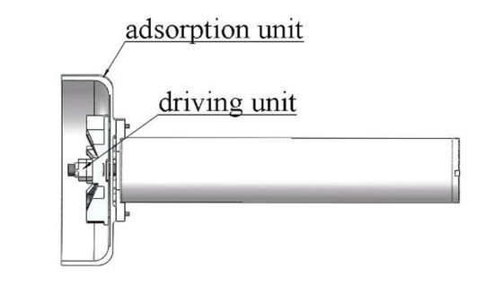
Figure 1.
Sectional view of absorber.
The vortex cover can isolate the internal and external water bodies. The velocity of the water body outside the cover is assumed to be zero, and fluid in the cover rotates at high speed with the bladed vortex disk. The area ratio δ of the disk to the vortex cover is as follows:
In the equation, d1 represents the outer diameter of the vortex cover and d2 represents the outer diameter of the vortex blade.
δ can be changed by keeping the area of the vortex cover constant and by changing the area of the blisk, as shown in Figure 2. The adsorption force of the absorber is generated by the circumferential motion of the fluid in the vortex cover, so the bladed vortex disk mainly focuses on the circumferential disturbance ability in the impeller. A group of 12 blades are symmetrically and evenly distributed around the center of the vortex blade.
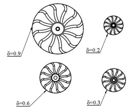
Figure 2.
Impeller of the vortex of the absorber.
2.2. Operating Principle
There is a common phenomenon of fluid flow in nature: the vortex [10]. Under the centrifugal force generated by rotational motion, pressure at the center is low, so there is a pressure difference between there and points outside the center. This leads to the generation of suction.
The absorber designed in this paper is based on the principle of vortex adsorption. The leaf disk drives flow in the vortex cover for high-speed rotation and then forms negative pressure in the vortex cover that results in an adsorptive force. There is a pressure difference between the inner and outer surfaces of the vortex cover, which generates the force towards the wall, namely the adsorption force. To facilitate calculation, we assume that the influence of the component of circumferential velocity of flow is much greater than that of axial velocity and the viscous effect of water owing to the high-speed rotational motion. The equation of motion of flow [11] in the dome of the vortex can be simplified as follows:
where ρ is the density of water, uθ is the circumferential component of velocity, r is the radial distance between rotational flow and the rotational axis, and P is pressure. In addition, water flow is driven by the blade of the fan to rotate, and thus, uθ can be considered to be consistent with the rotational speed of the fan blade, that is, uθ = ωr. ω is the angular velocity of rotation of the disk of the blade. The above equation can then be rewritten as follows:
By integrating Equation (2), we obtain
Equation (3) shows that p is proportional to the quadratic of r in the radial direction. Water pressures inside and outside the vortex cover are denoted by PR2 and Pa, respectively. The pressure difference between them is Δp, where R2 is the inner diameter of the vortex cover:
When Δp is not equal to zero, water flows inside and outside the vortex cover. When Δp is greater than zero, water flows from the vortex cover to the outside, and vice versa. However, because there is no inlet and outlet in the area surrounded by the wall and the vortex cover, there is no inlet and outlet in the stable state. The most reasonable explanation is Δp = 0, where PR2 = Pa. Taking P = Pa (r = R2) as the boundary Condition (3), the pressure distribution can be obtained as follows:
The pressure p is integrated at the surface of projection of the inner surface of the vortex cover to obtain the expression for the adsorption force F:
According to Equation (6),
- The adsorption force F is proportional to the quadratic speed.
- F is proportional to the fourth power of the inner diameter of the vortex cover.
3. Operating Performance of Underwater Absorber
3.1. Main Factors Influencing Adsorption Performance
As shown in Figure 3, the adsorption force of the absorber is related to the area of the vortex cover and the difference in pressure between the inside and outside of the vortex cover. This difference is affected by the factors below.
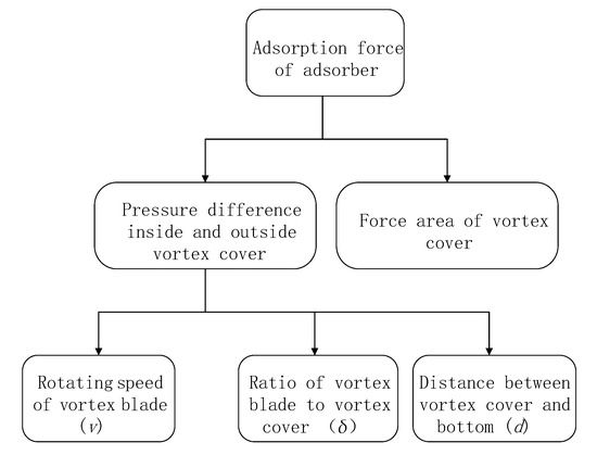
Figure 3.
Factors influencing adsorption performance.
v is equivalent to uθ in Equation (1) and is the circumferential component of velocity, v = ωr. The change in the force area of the vortex cover involves δ, so the size of the vortex cover is specified in this paper. Only the influences of v, δ, and d on the adsorption force of the absorber are explored. v was adjusted in the numerical simulation by setting different values for the rotational speed of the dynamic region of the absorber model, and different rotational speeds of the fluid in the dynamic region correspond to the different values of v. The input speed of the motor in the absorber could be changed directly in the physical test. Because the size of the vortex cover could not be changed, δ was changed by changing the size of the vortex blade; that is, the blade was scaled only in the X and Y directions and remained constant in the Z direction. In the physical test, the value of d was changed by lifting the absorber and by making it fall. In the numerical simulation, the distance between the wall and the bottom of the vortex cover was changed directly when the static domain was divided.
3.2. Numerical Simulation of Operating Performance
Different values of v, δ, and d were used in the numerical simulations. We used the control variable method, and the value of each variable is shown in Table 1.

Table 1.
Test statistics.
We simplified the physical model of the absorber to build a model for the numerical simulations. According to the working principle of the absorber, the main components of the system during operation are the high-speed rotating vortex blade, static vortex cover, and water in the environment as a moving medium. Therefore, in the model, the solid part was divided into the vortex blade, vortex cover, low-speed fluid outside the vortex cover, and high-speed fluid inside the vortex cover. The vortex blade needed to rotate along the vertical direction and the vortex cover remained static. The two parts of the fluid were disturbed only by the rotation of the vortex blade (uθ = v). The simplified model is shown in Figure 4.
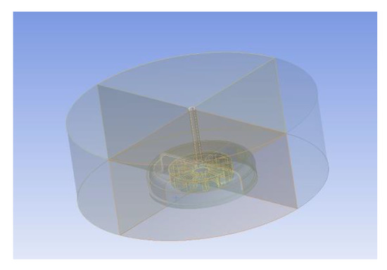
Figure 4.
Simplified diagram of geometric model.
Although the flow field inside the vortex cover of the absorber is complex 3D flow, the circular motion of water inside the hood of the eddy current of the absorber was dominant. A low-dimensional model could thus be used to approximate the characteristics of flow of water inside the vortex cover of the absorber (Figure 5 and Figure 6).
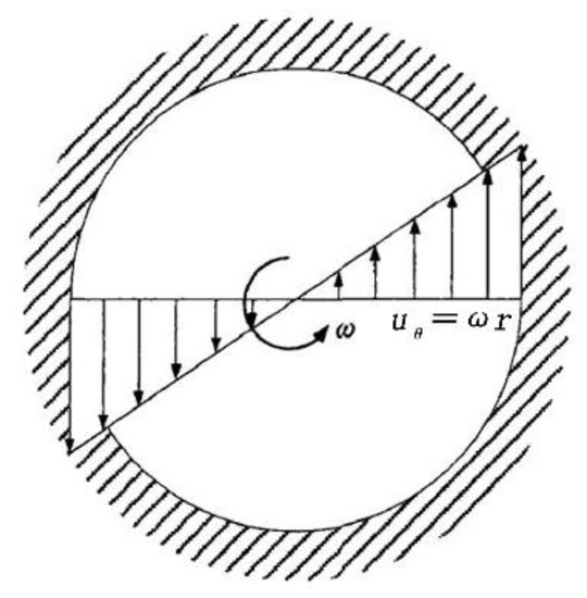
Figure 5.
Schematic diagram of flow velocity of water in the vortex cover.
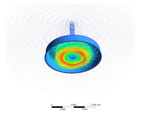
Figure 6.
Simulation nephogram of flow velocity of water in the vortex cover.
The following simplifying assumptions were made in the numerical simulations:
- (1)
- Water was regarded as an incompressible fluid.
- (2)
- Flow consisted mainly of circular motion. Gravity was ignored, as was disturbance in the Z direction of the leaf disk.
- (3)
- The inner surface of the vortex cover and the adsorption wall were assumed to be rigid surfaces that could not be penetrated.
The flow system of the absorber needed to follow the basic physical laws of conservation, including equations for the conservation of mass, momentum, and energy.
Equation of mass conservation:
Equation of momentum conservation:
Equation of energy conservation:
Incompressible fluid:
In the above equations, τij and ui are the tensors of viscous stress (i, j = 1, 2, 3) and the components of velocity, respectively; p and ρ are density and pressure, respectively; and e and k are the coefficient of heat conduction and the internal energy per unit mass, respectively.
Owing to the high-speed rotation of flow in the vortex cover, turbulence was a problem for the flow of the absorber and needed to be solved by the corresponding transport equation. An appropriate turbulence model needed to be chosen for this. The general desiderata of a model are high precision, simple application, short calculation time, and universality. The realizable k–ε-model can be used to describe the characteristics of rotational flow and to reflect the flow field and has loose requirements on computational performance. We thus used the realizable k–ε model to numerically simulate the internal flow of the vortex cover.
The simplified results of the absorber model show that the entire model could be divided into a dynamic and a static domain. The dynamic domain was where the vortex blade rapidly changed location. The mesh was more refined here than in the static domain, which made calculations possible. To improve the efficiency and accuracy of calculation, the vortex blade with a special shape and many irregular boundaries was divided by using a tetrahedral mesh, and a hexahedral mesh was used for other entities. The grid size was limited at the junction of the dynamic and static regions of the model to maintain good exchange between the regions. The boundary lines of variables with drastic changes in the model were limited to avoid the emergence of deformed grids.
The control size of the grid was adjusted to 0.5 mm, 1 mm, 1.5 mm, and 2 mm, and the initial results were compared with those obtained using a grid size of 1.5 mm. The results of grid division and calculation with different sizes are shown in Table 2 and Table 3.

Table 2.
Grid division table.

Table 3.
Results of calculation for grids with different sizes.
Table 2 and Table 3 show that changes in grid size had little effect on the results, and the maximum difference in F calculated after these changes was only 3%. Reducing the size of the grid increased the computational burden on the computer and prolonged the time needed for a solution. However, the model itself was small, and so a suitably small grid size was apposite. The model was finally meshed with 1.5 mm as the basic grid size. A total of 412,049 grid cells and 301,464 grid nodes with a comprehensive grid quality of 0.75 were generated in the computational domain of the absorber. The results of mesh generation are shown in Figure 7.
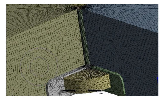
Figure 7.
Results of grid division.
The mesh used in the model was a sliding mesh, and thus, only transient calculations [12] could be carried out. The parameters used for the solution are shown in Table 4.

Table 4.
Solution settings.
3.3. Test of Physical Prototype
Different values of v, δ, and d were used to test the adsorption-related performance of the absorber. The control variable method was used in the test, and the values of each variable were identical to those in the numerical simulations.
According to the given requirements, the test platform (Figure 8) was composed of a water tank, absorber, fixed hoop, tension meter, adjusting pads, fixed beam, and camera. The water tank had dimensions of 1000 × 1000 × 500 (mm); the size of the pad was adjusted to 30 × 30 × 5 mm; d was changed by changing the number of adjusting pads; and the tension meter was calibrated with a range of 0–50 kg and a precision of 10 g. The camera was a WX605 industrial high frame rate camera; its frame rate was 330. The operation of the inner disk of the vortex cover was captured using high-speed photography.
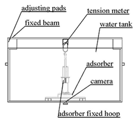
Figure 8.
Test scheme for the absorber.
When the indicator of the tension meter was stable, it was read directly (Figure 9). To reduce error, three tests were carried out under each set of conditions, and the average value of the tension meter was recorded each time.
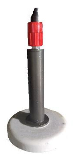
Figure 9.
Absorber object.
3.4. Analysis
Figure 10 shows the fitting of the F-v curves when δ = 0.2, 0.3, 0.6, and 0.9 in the physical test. The relationship between F and v was quadratic and was simulated by a quadratic polynomial. The experimental data and the curve of fitting were coincident, which proves that the above derivation is correct.
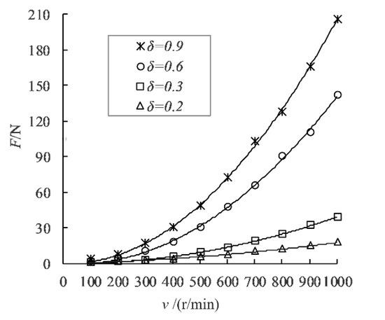
Figure 10.
F-v diagram (d = 5 mm).
Figure 11 shows the plots of F-d at v = 500 r/min, 700 r/min, and 1000 r/min when δ = 0.2. When v was consistent with δ, F decreased with an increase in d. When d exceeded a certain fixed value, F was stable and no longer changed with d. The fixed value of d was df, and the stable value of F was Fd.
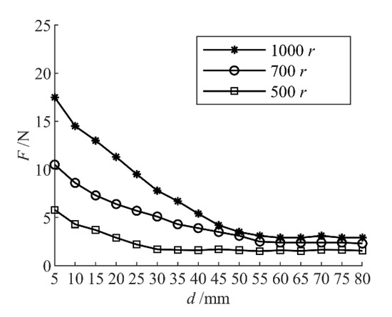
Figure 11.
F-d diagram (δ = 0.2).
To explore whether there was a correlation between df and δ, a group of control experiments with δ = 0.3 were used to obtain the broken line diagram of F-d at δ = 0.3, v = 500 rpm, 700 r/min, and 1000 rpm (as shown in Figure 12).
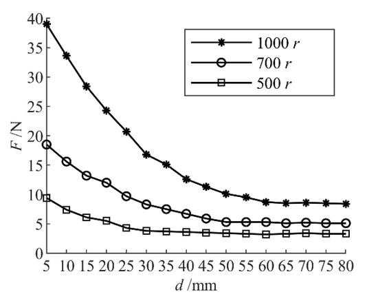
Figure 12.
F-d diagram (δ = 0.3).
δ = 0.2 when v = 500 rpm and df = 35 mm; when v = 700 rpm, df = 55 mm; and when v = 1000 rpm, df = 60 mm.
δ = 0.3 when v = 500 r/min and df = 35 mm; when v = 700 r/min, df = 55 mm; and when v = 1000 r/min, df = 60 mm.
The following can be concluded:
- (1)
- df had no relation to δ.
- (2)
- When δ was constant, df increased with v.
When δ = 0.2, v = 500 r/min and Fd = 1.6 N; when v = 700 r/min, Fd = 2.3 N; and when v = 1000 r/min, Fd = 2.9 N.
When δ = 0.3, v = 500 rpm and Fd = 3.5N; when v = 700 r/min, Fd = 5.1 N; and when v = 1000 r/min, Fd = 8.4 N.
The analysis shows the following:
- (1)
- Under the same value of v, Fd increased with δ.
- (2)
- Under the same value of δ, Fd increased with v.
Figure 13, Figure 14, Figure 15 and Figure 16 show the curves of F-v obtained from the numerical simulation and the physical experiment, respectively, with different values of δ at d = 5 mm. The results of the numerical simulation were consistent with the experimental results, and the average error was 5% (T stands for the result of the physical experiment and S stands for the result of the numerical simulation).
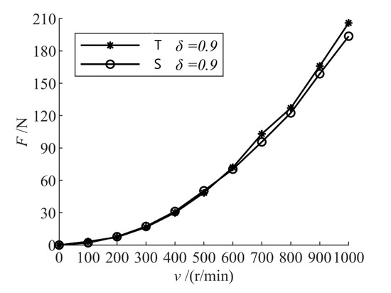
Figure 13.
F-v diagram (δ = 0.9, d = 5 mm).
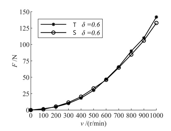
Figure 14.
F-v diagram (δ = 0.6 d = 5 mm).
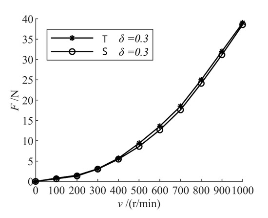
Figure 15.
F-v diagram (δ = 0.3, d = 5 mm).
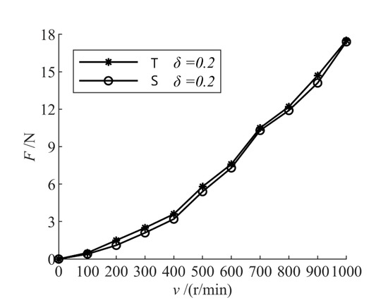
Figure 16.
F-v diagram (δ = 0.2, d = 5 mm).
The leaf disk drove the high-speed flow of water in the vortex cover. The internal water was limited by the wall of the vortex cover and was blocked by the vortex cover after acceleration. A large number of bubbles were formed in the area between the leaf disk and the vortex cover (Figure 17). However, the numerical simulation failed to take into account the influence of the bubbles, resulting in a deviation in the results. In addition, in the numerical simulation, we assumed that the fluid was ideal, whereas water was used in the experiment. This also had a certain impact on the experimental results.
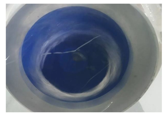
Figure 17.
Bubble inside hood of the vortex (δ = 0.6).
Figure 18, Figure 19, Figure 20 and Figure 21 show diagrams of the velocity vectors of the fluid in the fluid domain at different values of δ and r in the numerical simulation. Given that d = 5 mm, it can be concluded that the variation in fluid velocity in the shroud of the vortex along the radial direction to it was independent of δ and R. The velocity of the fluid in the shroud of the vortex increased from zero to its peak along the radial direction, which is consistent with the assumption in the analysis of the principle. Because the inner diameter of the shroud was not consistent with the diameter of the blade, the fluid reached the peak velocity between the inner wall of the shroud of the vortex and the disk of the blade and then decreased. The fluid outside the shroud was not affected by the rotation of the blade of the fan, and the velocity was zero.
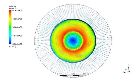
Figure 18.
(δ = 0.6, r = 1000).
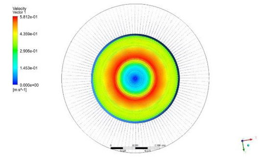
Figure 19.
(δ = 0.6, r = 100).
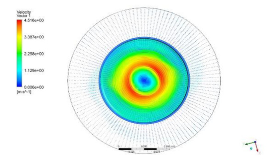
Figure 20.
(δ = 0.3, r = 1000).
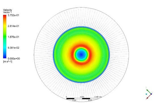
Figure 21.
(δ = 0.3, r = 100).
The F-d line charts of the numerical simulation and the physical experiment when δ was 0.2 are shown in Figure 22, Figure 23 and Figure 24. The following can be concluded from them:
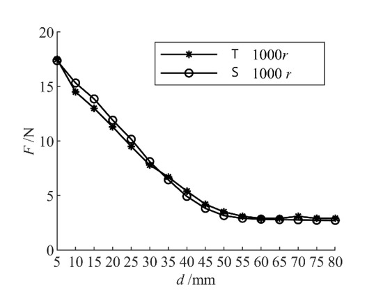
Figure 22.
F-d (v = 1000 r/min, δ = 0.2).
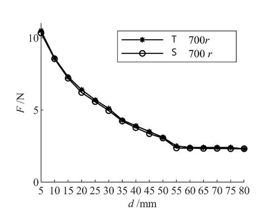
Figure 23.
F-d (v = 700 r/min, δ = 0.2).
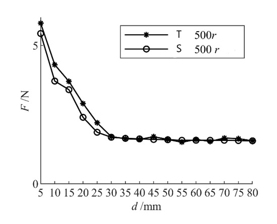
Figure 24.
F-d (v = 500 r/min, δ = 0.2).
- (1)
- The results of the numerical simulation in terms of F-d were consistent with the experimental results.
- (2)
- When δ = 0.2 and v = 500 r/min, error in the numerical simulation reached its maximum value of 10.8%; when δ = 0.2 and v = 700 r/min, the minimum error of 2.7% was obtained.
A comparison of the results of the numerical simulations and the prototype experiment shows that they were consistent, which verifies the correctness of the theoretical analysis and the numerical simulations. The following can be concluded:
- (1)
- There is a quadratic relationship between the absorber F and v.
- (2)
- F decreases with the increase in d, and the law of distribution of fluid velocity in the dome of the vortex is independent of d. When d exceeds a certain fixed value, the value of F becomes stable.
- (3)
- F increases with the increase in δ, and the distribution of fluid velocity in the vortex cover is independent of δ.
4. Conclusions
This study conducted numerical simulations and a physical test of an underwater absorber. The results of the numerical simulation were consistent with those of the physical test. The flow field inside the vortex cover of the absorber was also consistent with the assumption in the derivation of the absorber adsorption principle. The following conclusions can be drawn:
- (1)
- When v was identical to d, F increased with δ. A larger δ meant that the larger the range of direct influence of the blade on fluid in the vortex cover was, the greater the peak velocity of the fluid in the vortex cover was at the same speed and that the greater the velocity of fluid in the vortex cover was, the greater the adsorption force was. In the practical application of the absorber, when we cannot make the size of the absorber larger, we can consider increasing the speed of the blade. Moreover, the adsorption force of the absorber is quadratically related to the rotational speed of the fan blade and the increase in the rotational speed still greatly improves the adsorption force of the absorber.
- (2)
- When v and δ were identical, F decreased with d. When d increased to a certain fixed value, namely df, F did not change. This was a stable value, namely, Fd. df was independent of δ and increased only with v. Under the same value of v, Fd increased with δ; under the same value of δ, Fd increased with v. That is, when the absorber needs to be far away from the wall, the absorber with larger δ can be selected; when the absorber needs to be close to the wall, the larger v absorber can be selected.
- (3)
- When d and δ were identical, F increased with v, and there was a quadratic relationship between them. The law of distribution of fluid velocity in the vortex cover was independent of δ.
- (4)
- The numerical simulations used here represented only some phenomena, and the results were inaccurate. Error with data from the physical test was large in many cases. In the physical experiment, prominent bubbles were observed inside and at the bottom of the vortex cover. The gas–liquid two-phase flow phenomenon was not realized in the numerical simulation, and only the rotation of single-phase water was implemented.
This absorber was used in an ROV and provided a stable and reliable adsorption force for it so that it could remain stably on the wall and carry out its task. In addition, the absorber can control the adsorption force according to the given demand, which significantly improves the motion of the ROV. Tests in a pool and on a wharf (Figure 25 and Figure 26) showed that the absorber can meet the application-related requirements of the ROV.
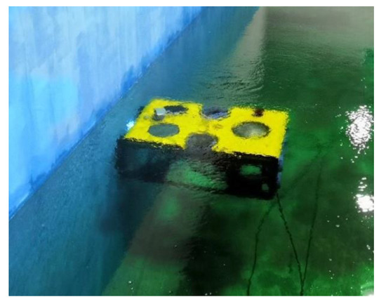
Figure 25.
ROV pool test.
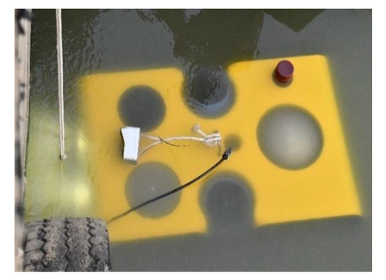
Figure 26.
ROV wharf test.
Author Contributions
Conceptualization, P.X. and C.H.; methodology, C.H.; software, P.X. and C.H.; validation, C.H., T.L. and H.C.; formal analysis, C.H.; investigation, C.H.; resources, P.X.; data curation, H.C.; writing—original draft preparation, C.H.; writing—review and editing, C.H.; visualization, C.H.; supervision, P.X.; project administration, H.C.; funding acquisition, P.X. All authors have read and agreed to the published version of the manuscript.
Funding
This work has been supported by the National Natural Science Foundation of China (52071131), Marine Science and Technology Innovation Project of Jiangsu Province (HY2018-15), National Key Research and Development Program of China (2018YFF0215005), and China Postdoctoral Science Foundation (2018M640390).
Institutional Review Board Statement
Not applicable.
Informed Consent Statement
Not applicable.
Data Availability Statement
Not applicable.
Conflicts of Interest
The authors declare no conflict of interest.
References
- Xu, Y.; Li, P. Development trend of underwater vehicles. Nat. J. 2011, 33, 125–132. [Google Scholar]
- Tan, J.; Tian, J.; Wang, M. The present situation of underwater robot technology and its application prospect in water conservancy industry. China Water Conserv. 2018, 6, 33–36. [Google Scholar]
- Xu, J.; Wang, Y.; Hou, B.; Yang, L. R&D status and development trend of ROV. J. Sichuan Ordnance Ind. 2011, 32, 71–74. [Google Scholar]
- Bessa, W.M.; Dutra, M.S.; Kreuzer, E. Dynamic Positioning of Underwater Robotic Vehicles with Thruster Dynamics Compensation. Int. J. Adv. Robot. Syst. 2013, 10, 325. [Google Scholar] [CrossRef]
- Liu, H.; Zhang, M.; Ceng, Q.; Qi, X.; Song, Z. Research on dynamic positioning of underwater robot against wave disturbance. Comput. Meas. Control 2016, 24, 199–203. [Google Scholar]
- Jiang, H.; Yang, X.; Jiang, H.H. Design and implementation of a climbing robot with adsorption and peristalsis for ships. Ship Sci. Technol. 2010, 32, 31–34, 38. [Google Scholar]
- Peng, J.; Li, J.; Shao, J.; Li, J. Research on suction system of negative pressure wall-climbing robot. China Mech. Eng. 2012, 23, 2160–2164, 2168. [Google Scholar]
- Zhang, B.; Zhu, R.; Yang, J.; Zhang, G. Study on adsorption capacity of climbing robot with compound adsorption. Mech. Des. Manuf. 2016, 250–252, 255. [Google Scholar]
- Zhang, Y.; Fu, G.; Guang, L. Design of controllable underwater adsorption structure model based on electric screw. J. Ocean Technol. 2018, 37, 40–43. [Google Scholar]
- Li, X.; Kagawa, T. Non-Contact Conveyance Equipment. U.S. Patent 20130272803, 27 December 2011. [Google Scholar]
- Cai, Z.; Luo, S. Calculating 3D viscous flow in turbomachinery by finite volume method. J. Huazhong Univ. Sci. Technol. 2000, 9, 72–75. [Google Scholar]
- Wang, F. Computational Fluid Dynamics Analysis: Principle and Application of CFD Software; Tsinghua University Press: Beijing, China, 2004; pp. 39–45. [Google Scholar]
Publisher’s Note: MDPI stays neutral with regard to jurisdictional claims in published maps and institutional affiliations. |
© 2022 by the authors. Licensee MDPI, Basel, Switzerland. This article is an open access article distributed under the terms and conditions of the Creative Commons Attribution (CC BY) license (https://creativecommons.org/licenses/by/4.0/).