Article

Integrated Dynamics Response Analysis for IEA 10-MW Spar Floating Offshore Wind Turbine

1
Huaneng Clean Energy Research Institute, Beijing 102209, China
2
Department of Civil Engineering, Faculty of Infrastructure Engineering, Dalian University of Technology, Dalian 116024, China
3
South Branch of China Huaneng Group Co., Ltd., Guangzhou 510620, China
4
Deepwater Engineering Research Centre, State Key Laboratory of Coastal and Offshore Engineering, Dalian University of Technology, Dalian 116024, China
5
Research Institute, Dalian University of Technology, Shenzhen 518057, China
6
Institute for Earthquake Engineering, Faculty of Infrastructure Engineering, Dalian University of Technology, Dalian 116024, China
*
Author to whom correspondence should be addressed.
These authors contributed equally to this work.
J. Mar. Sci. Eng. 2022, 10(4), 542; https://doi.org/10.3390/jmse10040542
Submission received: 11 February 2022 / Revised: 10 April 2022 / Accepted: 11 April 2022 / Published: 14 April 2022
(This article belongs to the Special Issue Offshore Wind Energy)

Abstract

:
Wind energy in the deep-sea area is more abundant and the capacity of wind turbines can be made larger. Therefore, the research on deep-sea floating offshore wind turbines will be the primary strategy for wind energy exploitation in the future. The spar-type platform depends on the characteristics of a small water plane, deep draft, and good stability, which has been applied to the commercial development of deep-sea wind energy. In the next ten years, the 10-MW wind turbine will become the mainstream class installed in the floating offshore wind turbine farm. Thus, it is very necessary to conduct a comprehensive and in-depth study on the 10-MW spar type floating offshore wind turbine. The direct-drive 10-MW offshore wind turbine was proposed by the International Energy Agency (IEA) in Wind Task 37 in 2019. In this paper, a spar-type platform is designed to support the IEA 10-MW reference wind turbines, and a nonlinear aero-hydro-servo-elastic numerical model is established using the FAST tool (which is developed by the National Renewable Energy Laboratory, NREL). Then, the accuracy of the wind turbine and the sensitivity of the controller are verified, and the natural periods of the floating offshore wind turbine are obtained by free-decay tests. The natural periods of the platform in six degrees-of-freedom are found to be within the range recommended by the design standard. The measured wind and wave data of the target site close to Fujian Province of China are used to evaluate the performance of the floating offshore wind turbine under the 100-, 50-, 5-, and 2-year-return stochastic weather conditions. The results indicate that the design of the spar platform is reasonable and has excellent hydrodynamic performance.

1. Introduction

In recent decades, marine renewable energy has been paid more and more attention by governments worldwide, among which wind energy is the most promising clean energy. The development and utilization of wind energy will significantly slow down global warming and reduce CO2 emissions [1,2]. The medium to exploit wind energy is the wind turbine and the primary offshore wind turbines in service have bottom-fixed foundations at present. To reduce and eliminate noise and visual pollution, the exploitation of offshore wind energy will move from shallow waters (water depths smaller than 50 m) to deeper waters in future research. Meanwhile, the costs of wind turbine construction and installation will increase with the water depth for the bottom-fixed foundations. Thus, the floating foundations will become an inevitable choice [3,4,5]. The commercial advantages of floating offshore wind turbines (FOWTs) in the deep-sea area are obvious, such as larger-scale wind turbines, superior wind resources in the deep sea, less noise, and visual pollution [6,7,8]. At present, the main types of offshore wind turbines are spar platform, tension-leg platform (TLP), semi-submersible platform, and barge platform. The spar platform has many advantages compared to the other three platforms. It has a better hydrodynamic performance because of the characteristics of a small water plane, deep draft, lower center of gravity; during the installation phase, many challenges of tension-leg installation will arise, while it is relatively convenient for the spar. Moreover, the spar platform is a simple structure and it has a lower steel consumption and construction cost. Therefore, the spar-type platform has been applied to the commercial exploitation of deep-water wind energy [9,10,11,12].
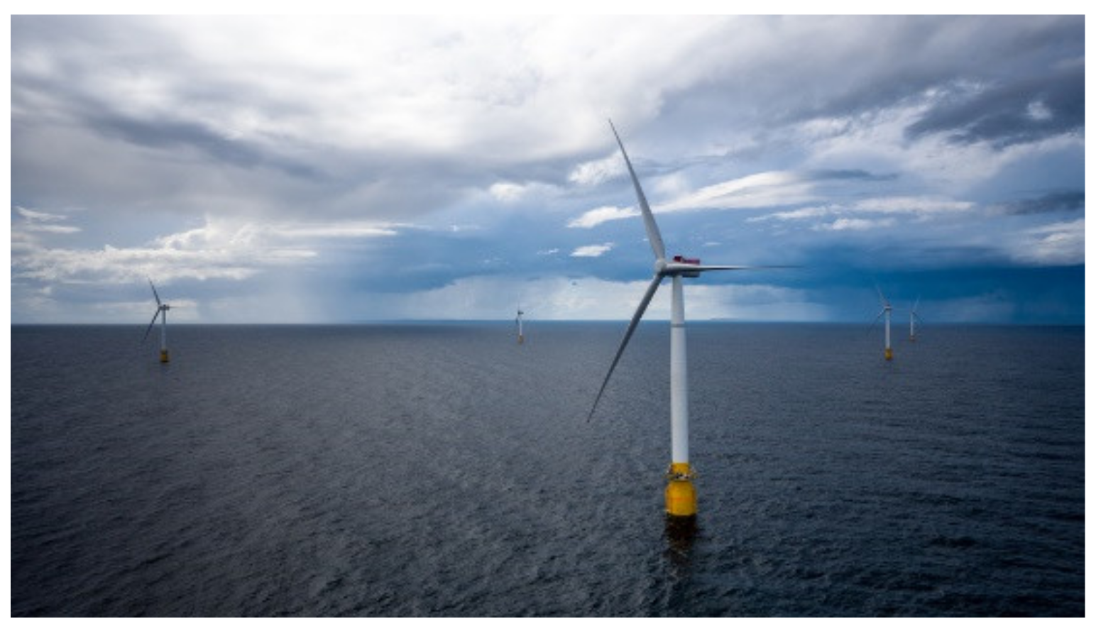
With the consideration of spar-type FOWTs developed earliest, it has become the most mature technology. At present, the spar-type FOWTs have been used for commercial power generation in England. The world’s first spar-type FOWT prototype test at sea is called the Hywind Demo (Figure 1), and this test project began in 2009 and lasted eight years. The power capacity of the wind turbine is 2.3-MW, the draft depth is 100 m, the hub height is 65 m, the rotor diameter is 85 m, and the water depth is 220 m. The Hywind Demo produced 7.3 million kWh electricity in its first test year and successfully withstood wind speed of 40 m/s and wave height of 19 m over the test course of eight years [13]. In 2015, six years after the Hywind Demo prototype test, Equinor (called Statoil before), considering that the concept of Hywind was mature and cost-effective, could be used for commercial development. In 2017, the world’s first commercial floating offshore wind farm, the Hywind Scotland (Figure 2), underwent construction. The power of the turbine is 6-MW, the draft depth is 78 m, the hub height is 98 m, the diameter of the rotor is 154 m, and the water depth is 95–120 m. The average wind speed is 10 m/s, and the average wave height is 1.8 m in this sea area. We can find that the draft depth and water depth of Hywind Scotland are all less than Hywind Demo, but the other performances of Hywind Scotland are all significantly superior to Hywind Demo [14].
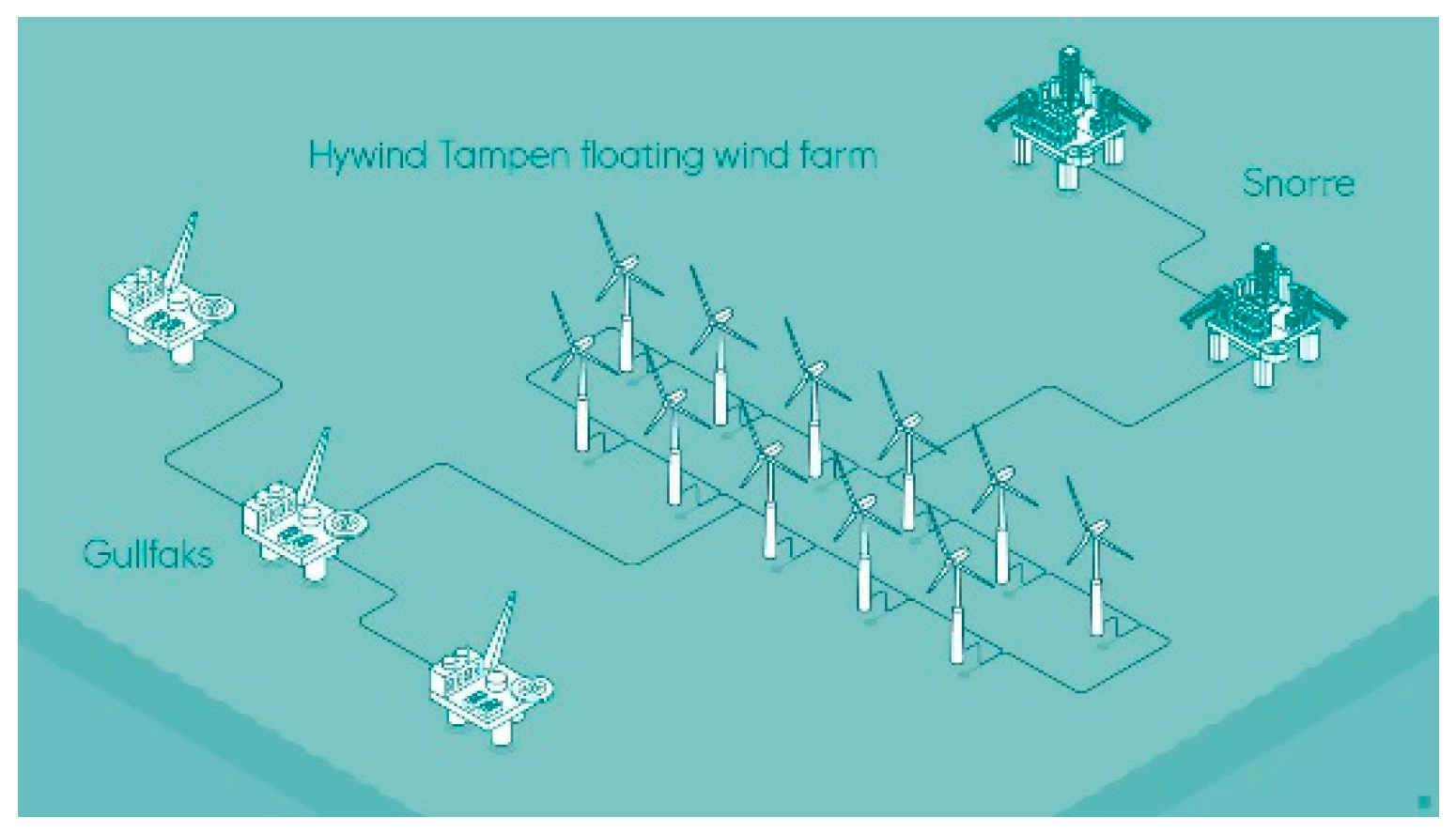
If the scale of Hywind Scotland is relatively small and still in an experimental phase, then the upcoming project Hywind Tampen in Norway will further demonstrate the reliability of the Hywind scheme. The Hywind Tampen project is different from the wind farm constructed previously. The Norwegian residents are not the consumer of the electricity generated by the Hywind Tampen farm. The five Oil & Gas platforms, Gullfaks and Snorre, that are nearby will be the main electricity user (Figure 3). The construction of the Hywind Tampen wind farm began on 1 October 2020 and is expected to be completed in the second half of 2022. The power of the turbine is 8-MW, the diameter of the rotor is 167 m, and the water depth is 260–300 m. In addition, the foundation (spar platform) of the Hywind Tampen project will be constructed with concrete instead of steel, which will lead to a decrease of 40% in cost compared with Hywind Scotland. Hywind is the first one commercial floating wind turbine technology, but the costs are still significantly higher than the bottom-fixed foundations located in shallow water. Thus, there are still many efforts that need to be made before the construction investment is acceptable and the FOWTs technology is suitable for the deep-water [15]. In addition to the spar-type floating platform, the semisubmersible floating platform has also been used in offshore wind farms as pilot park projects, such as the 25 MW offshore wind farm WindFloat Atlantic project [16] and 50 MW Kincardine project [17].
From the introductions above, it can be concluded that the 10-MW class wind turbines will be the trend of FOWTs in the next ten years. This is because large-scale wind turbines are believed to be advantageous from an investment and installation perspective [18]. Therefore, the research on the 10-MW FOWTs has great significance and will be a guide for future practical projects. In 2013, Technical University of Denmark (DTU) published the DTU 10-MW Reference Wind Turbine [19], later, in 2019, IEA also proposed an offshore direct-drive 10-MW wind turbine. However, due to the DTU 10-MW published previously, there is a lot of research on it.
Many efforts have been performed by scholars of Norwegian University of Science and Technology (NTNU) on 10-MW wind turbines, they designed many foundations to support the DTU 10-MW reference wind turbines (RWT), including bottom-fixed foundations, semi-submersible type floater [20,21], TLP type floater [22,23], spar type floater [24,25,26]. Son et al. [27] designed a new WindFloat type semi-submersible platform to support the DTU 10-MW wind turbine. The OpenFAST and OrcaFAST are used to predict the performance of the WindFloat, and the numerical results show that the platform has an excellent hydrodynamic performance. Shin et al. [28,29] also designed a semi-submersible platform to support the DTU 10-MW RWT and a scale ratio of 1:90 model test was performed at the same time, the characteristics such as the effective amplitude response operator (RAO) and six degree of freedoms (DOFs) motion of platform under regular waves and irregular waves were examined. Especially the response of the platform under the action of the 2nd order wave effect was focused on in their research. Leble and Barakos [30] investigated the possibility of a 10-MW wind turbine entering a vortex ring state during pitching and yawing motion. The results show that the vortex ring state is existent during oscillations and has a strong effect on the frequency and amplitude of wind turbines. Jeong and Kim [31] based on the computational fluid dynamics method to explore the flatback airfoil effect on the 10-MW wind turbine blade.
Considering the low material costs and expected high durability, concrete is treated as an alternative to steel for the construction material for floating platforms of wind turbines, and Equinor also plans to use concrete as substructures for the Hywind Tampen project. Oh et al. [32] designed a spar-type platform using prestressed concrete to support the DTU 10-MW; the diameter of the spar is 16 m and the wall thickness is 0.45 m. Serafeim et al. [33] used the passive load control methods to reduce the blade weight of DTU 10-MW. Through the optimization design of the structure, the blade mass and the bending moment at the root of the blade are reduced by 10% and 5%, respectively. Bredmose et al. [34] designed a Triple Spar platform, which is a hybrid between spar and semi-submersible with the advantages of both of them. A 1:60 scale model test was performed under the acting of wind and wave, and the active blade pitch control first was interesting. From the above literature review, we can know that the research on DTU 10-MW is relatively abundant, while the research on IEA 10-MW is scarce, this is because the DTU 10-MW was released early (in 2013) than IEA 10-MW (in 2019). Recently, the IEA 10-MW has been widely investigated and has often been used as a benchmark; hence, it has also been used in this research. The main aim of this research is to verify the feasibility of the spar platform to support the IEA 10MW based on Chinese local environmental conditions.
The current design of the floating platform supporting a 10-MW wind turbine is of significant interest to the industry as it is a necessary milestone to develop deeper water sites commercially. However, academic research on 10-MW wind turbines is not very abundant. In this paper, the wind turbine version we used is the IEA 10-MW RWT and the spar platform and mooring system are redesigned based on Bachynski’s research, while the OC3-Hywind [35] is used as a reference at the same time. The combination of IEA 10-MW RWT and this newly designed spar platform is then studied. The environmental conditions of the target site close to Fujian Province of China are used to evaluate the performance of the FOWT. Thus, to implement this research, the organization structure of this paper is organized as follows:
In Section 2, the parameters of the IEA 10-MW wind turbine and the spar platform and mooring line are introduced. In Section 3, the numerical model of the IEA 10-MW spar type FOWT is established in FAST v8 [36] and the accuracy of the model and the sensitivity of the controller are verified. In Section 4, the platform motion, nacelle acceleration, and the mooring tension of the numerical model under some typical cases are performed. The main conclusions and future works are presented in Section 5.

2. Specification of IEA 10-MW and Spar Platform

2.1. Design Parameters of the IEA 10-MW

From the IEA report [37], it still has several areas for potential improvement for DTU 10-MW. The controller, for example, still needs to be sufficiently developed as the drivetrain design is not detailed, and although it is a better direct-drive version, the structural design of the blade is not detailed. Thus, the main objective of the IEA Wind Task 37 is to solve these common questions. In 2019, the IEA 10-MW RWT was released, and the overall characteristics of the offshore turbine designed for the IEA Wind Task 37 are based on the DTU 10-MW RWT. The turbine is developed to have a rated electrical power of 10-MW, and this turbine is a direct-drive version generator. The key parameters of the IEA 10-MW compared to the DTU 10-MW RWT are listed in Table 1. The steady-state operational data for the 10-MW turbine are listed in Table 2.

2.2. Parameters of the Spar Platform and Mooring System

Here we are using a spar platform designed based on the OC3 Hywind and NTNU [38], and the draft is the same as the original OC3 spar. But the diameters of two cylinders are increased to provide enough buoyancy. The bottom of the steel cylinder is filled with concrete ballast to achieve the expected draft. The density of concrete ballast is 2600 kg/m3, and the density of steel is 7850 kg/m3. The wall thickness of the steel cylinder is 6 cm. The project of the mooring system is also the same as the OC3 Hywind, which consists of three catenary lines. An added yaw stiffness from the mooring system is represented by a rotational spring. Based on previous experience, if the fairleads are located at a depth of the total center of gravity (CoG) of the system, it will reduce the coupling between surge and pitch motion; thus, the fairlead depth is designed as 77.0 m below still water level (SWL). Based on the reference [38], the platform mass was modified from 1.21 × 10⁷ kg to 1.381 × 10⁷ kg, and the mooring line mass density was modified from 233.1198 kg/m to 245.4 kg/m. Other parameters can be found in Table 3 and Table 4 for detailed information.

3. Model Validation

3.1. Modeling in FAST

The numerical model of the spar FOWT was built using the fully coupled aero-hydro-servo-elastic-mooring simulation tool FAST. The external force acting on the FOWT system mainly comes from the aerodynamic loads acting on the wind turbine and the hydrodynamic loads acting on the platform, as well as the mooring tension from the mooring system. The periodic aerodynamic forces and randomly fluctuating aerodynamic forces, which are calculated in the AeroDyn module within the FAST code. The influence of the wake and the blade airfoil aerodynamics are calculated based on Blade Element Momentum (BEM) theory. The effect of the tower on the blade is accounted for in the AeroDyn module based on a combination of potential flow and tower shadow models.
The hydrodynamic and hydrostatic induced load and the mooring tension are calculated by HydroDyn and MoorDyn, respectively. The additional linear damping model in OC3 Hywind is used here to calculate the additional damping force. The viscous drag coefficient, CD, is taken to be 0.7, according to DNVGL-ST-0437 [39]. The typical wave spectrum, JONSWAP, was used to determine the irregular wave condition in the HydroDyn input file. The hydrodynamic load is calculated by the potential flow theory. The hydrodynamic-added-mass and -damping matrices and hydro-static matrix were obtained from the hydrodynamic analysis tool, ANSYS AQWA [40]. The hydrodynamic coefficients output files from AQWA are transformed to WAMIT for-mat and fed into the FAST main program.

3.2. The Operational Indicators of Turbine

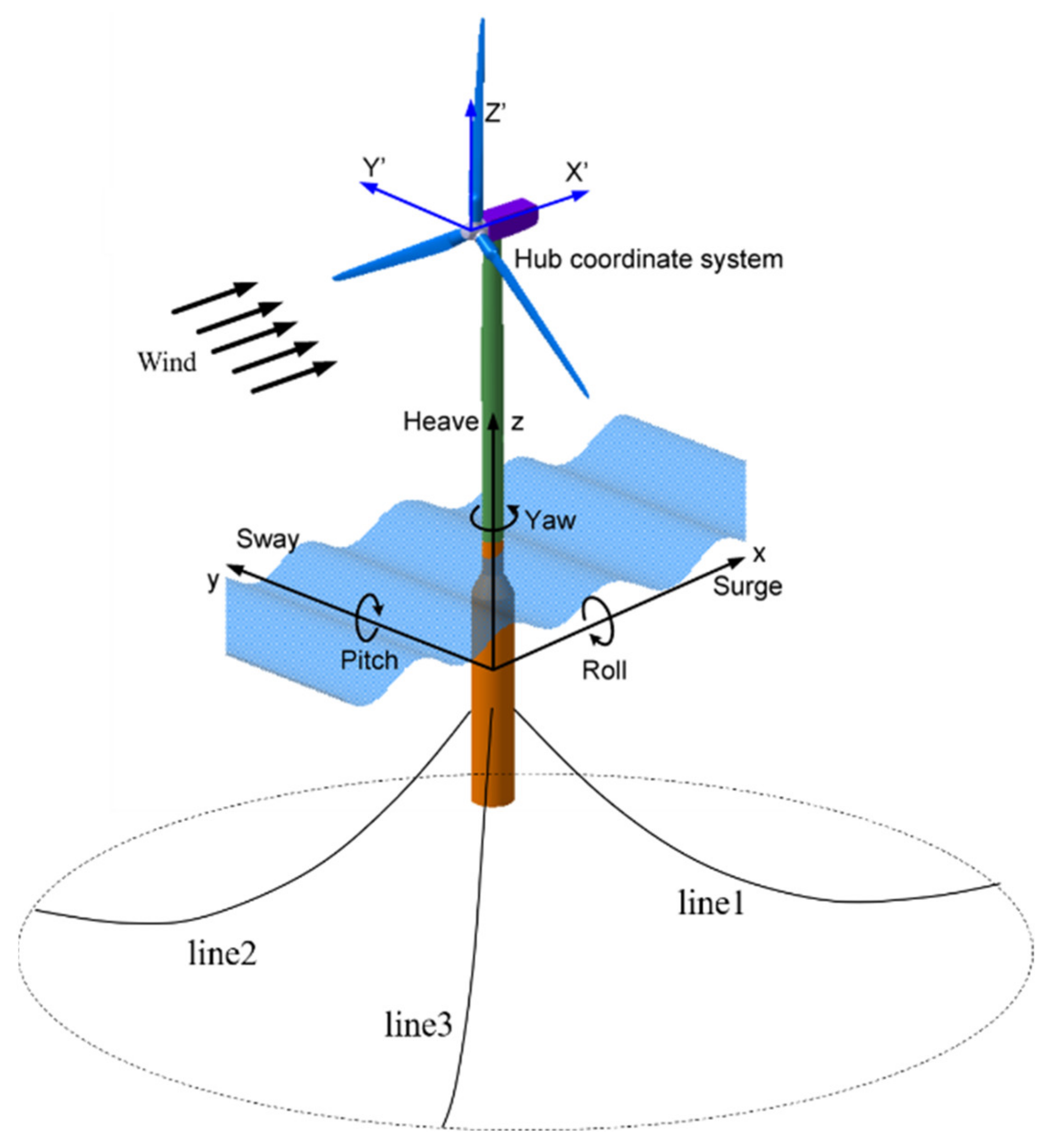
In this section, the 6 DOFs of the floating platform are limited to zero, then the generator power, blade pitch angle, rotor speed, and rotor thrust of the IEA 10-MW wind turbine are calculated under the action of different steady-state wind. The direction of wind along with the positive of the x-axis. Figure 4 is the schematic diagram of the coordinate system in FAST.
It can be seen from Figure 5 that when the wind speed is less than the rated wind speed, the control strategy is to keep the blade pitch angle always at 0° and to increase the rotor speed to achieve the optimum generator power. When the wind speed reaches the rated value, the blade pitch angle controller starts working, the generator power, rotor thrust, and rotor speed reach the maximum value; then, as the wind speed continues to increase, the generator power and rotor speed remain unchanged, the blade pitch angle increases with the increase in wind speed, but the rotor thrust decreases with the increase in wind speed. As IEA 10MW is designed as a direct drive, thus, the rotor speed is lower than DTU 10MW. The rotor thrust of IEA 10MW reaches the maximum when the wind speed is 10.5 m/s, while DTU 10MW is 11.5 m/s.

3.3. Controller Sensitivity

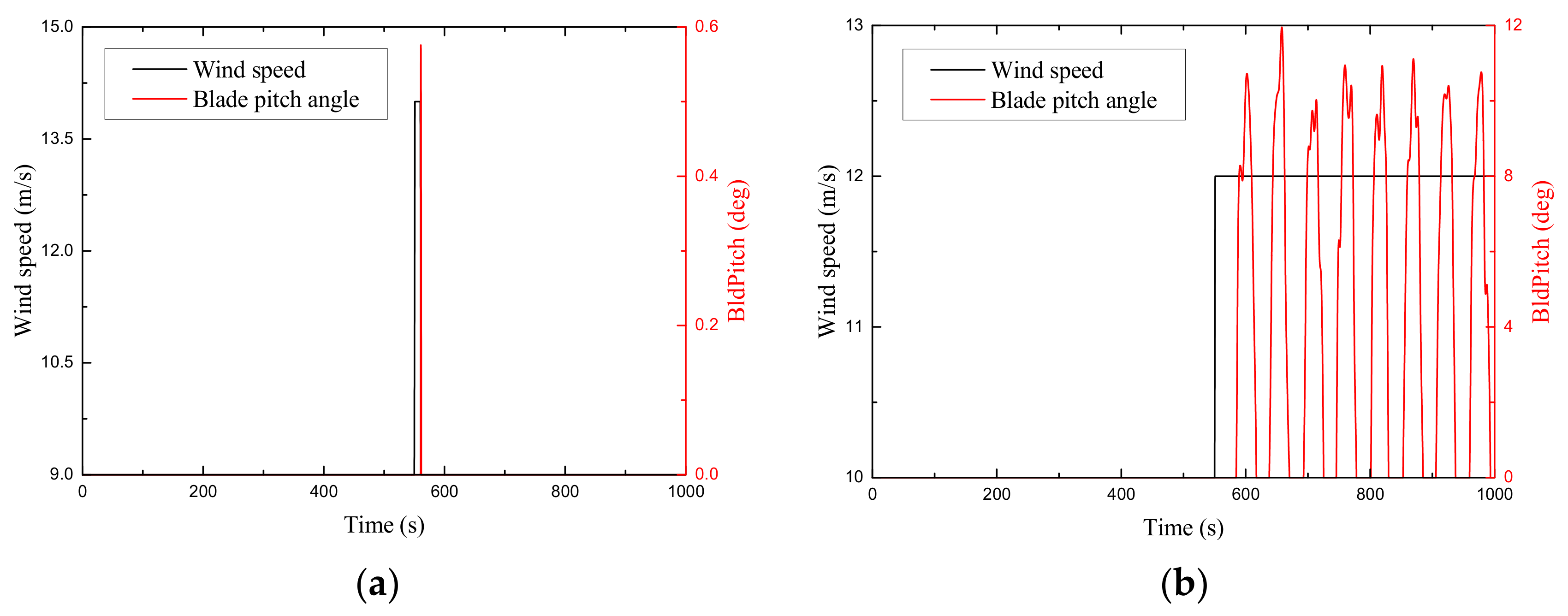
The ROSCO controller [41] is used for the IEA 10-MW wind turbine; here, its sensitivity is tested. The first case is a 9 m/s steady-state wind with a pulse of 5 m/s; the second case is a step steady-state wind from a 10 m/s jump to 12 m/s. The six DOFs of platform motion are free. The responses of the controller are shown in Figure 6. From the results, we can see that the controller reacts quickly to the wind change; thus, the controller is sensitive.

3.4. Natural Periods

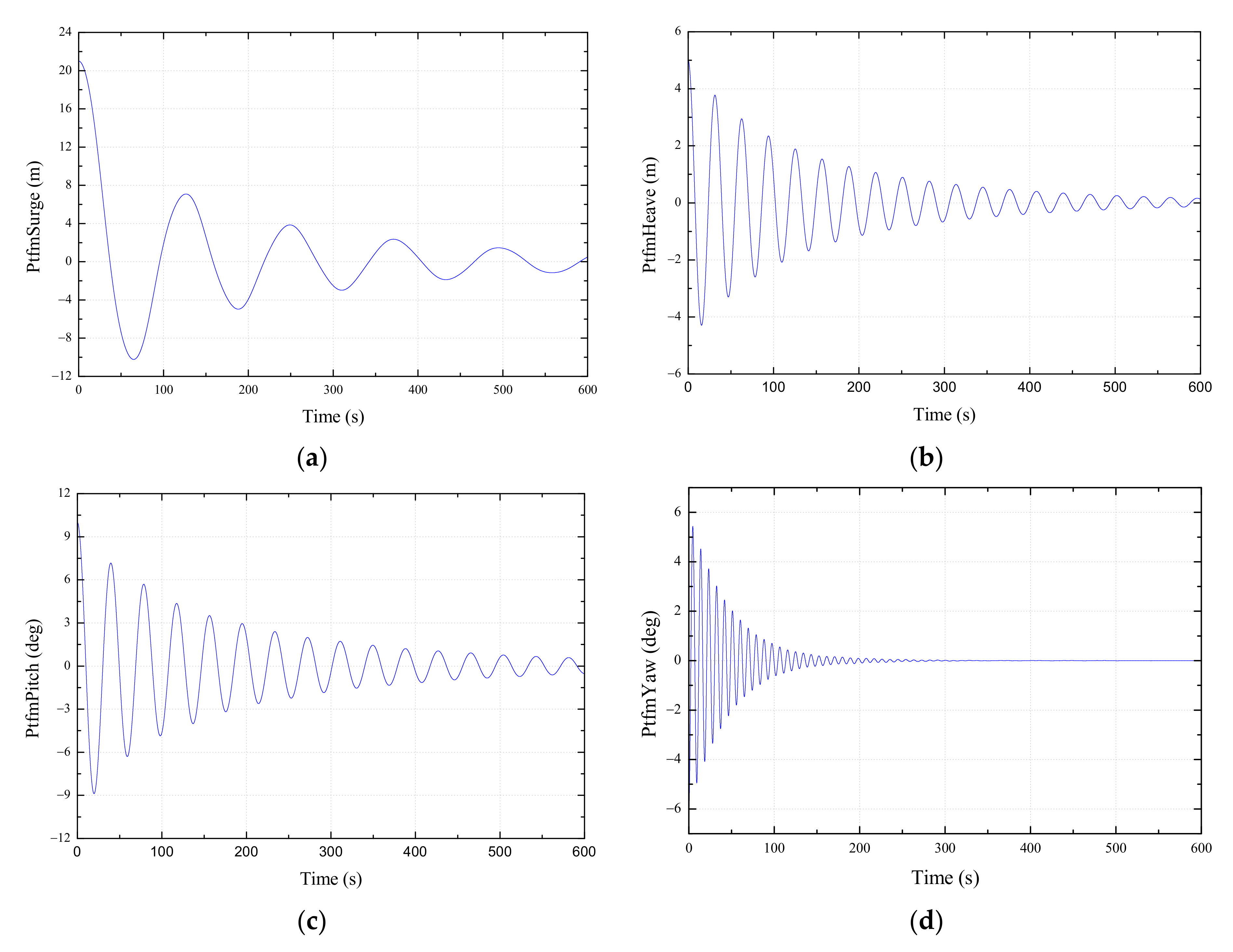
The major energy contained in ocean waves usually ranges from 5 to 25 s of the wave spectral period; thus, in the design process, the natural periods of the FOWT should avoid this particular wave spectral range. This is because keeping the natural periods of FOWT out of the major wave spectral period can avoid the resonance problem. Usually, the natural period of the heave motion of the spar platform is around 20 to 25 s and the pitch and roll motion are around 30 s. The natural periods of the spar platform can be obtained by decay analysis. Due to the symmetry of the spar structure, only surge, heave, pitch, and yaw need to be considered for the decay tests. The decay curves are shown in Figure 7 and the natural periods are listed in Table 5. According to the performance of the decay test, the natural periods of the IEA 10-MW spar type FOWT established in this paper are acceptable.

4. Results and Discussions

4.1. Environmental Parameters

Under the operation condition, the FOWT is subjected to the combined action of wind and wave loads. Thus, the performance of the platform motion response should deserve more attention under the coupled action of wind and waves. To comprehensively investigate the survivability of the FOWT, the operational and extreme environmental conditions for 100-, 50-, 5-, 2-years return periods are considered. The JONSWAP spectrum defines the random waves; there are three current models in FAST; here, we use the Near-Surface model. The waves and current models are plotted in Figure 8. The turbulence wind is generated by TurbSim [43], the Normal Turbulence Model (NTM), and the class C defined in the IEC standard for turbulence wind is used here for offshore condition turbulent [44]. The wind speed in hub height and the speed distributed over the whole wind farm are shown in Figure 9. The significant wave height, the wave peak periods, the current speed, and the mean wind speed are listed in Table 6. A total of 24 typical dynamic load cases (LC) are defined; these LCs are determined based on the wind and wave data measured at the target site close to Fujian Province, China, provided by Huaneng Clean Energy Research Institute. The current velocity is defined based on Zhang’s research [45]. Only one direction of the wind, wave, and current is considered because the spar platform is a cylinder, the direction of the wind, wave, and current is traveling along the x-axis positive. For LC13 to LC24, the turbine is set to be parked and the pitch angles of the blade are feathered to 90° as the mean wind speed exceeds the cut-out speed. Each case is run for 4800 s, while the first 1200 s are removed to exclude the transient effect of the startup.
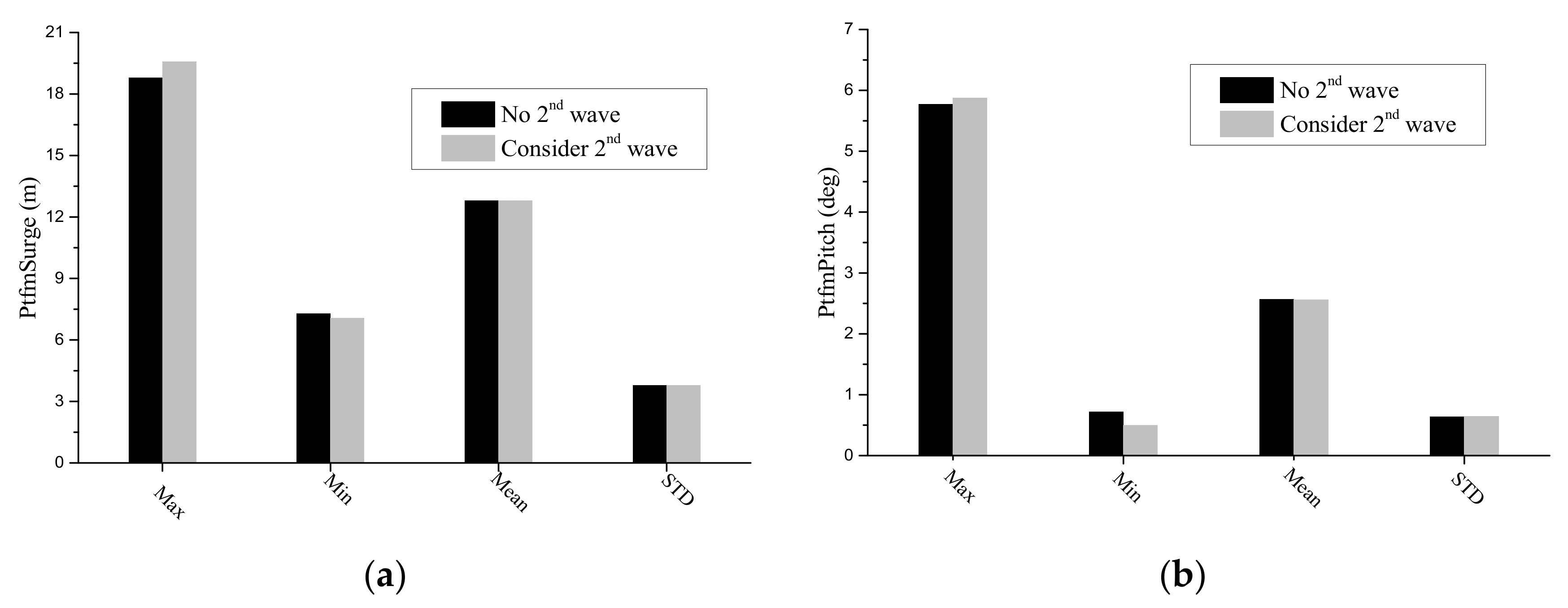
Firstly, the effect of the 2nd order wave loads on the spar platform is studied. The results are shown in Figure 10 and from the figures, we can see that both with or without considered 2nd order wave loads have little influence on the spar surge and pitch motion responses, while only the maximum and minimum values have slight differences, the mean-values, and standard deviation are equal. Thus, the 2nd order wave loads will be neglected in all dynamic load cases.

4.2. Platform Motions Response

The maximum (Max), minimum (Min), mean value (Mean), and standard deviation (STD) of the platform motions in 6 DOFs for the 24 load cases are shown in Figure 11, Figure 12, Figure 13, Figure 14, Figure 15 and Figure 16. The results demonstrate that this FOWT can survive in the 100-year return extreme weather conditions. Moreover, some conclusions can also be drawn. Considering the wave and wind are all propagating along the direction of x-axis positive; thus, the amplitude of the platform surge and pitch are very significant and the amplitude of the platform motion in the other 4 DoFs are relatively small. For surge and pitch motion, when the wind turbine is under operating, the platform motion responses are larger than that when the wind turbine is under parked. The maximum surge motion nearly reaches 25 m, the pitch angle nearly reaches 9°, and the surge amplitude is less than 1/10 of the water depth. For sway and heave and roll motion, when the wind turbine is under operating, the platform motion responses are smaller than that when the wind turbine is under parked. This is because the thrust and overturning moment generated by the wind leads to a significant platform motion. It also illustrates that the operation condition is the most dangerous condition for FOWTs. For yaw motion, because of the rotor gyroscopic effect, the platform motion responses of the wind turbine under operating are larger than when parked. In addition, the differences in platform motion responses with or without current are not significant. For all 24 load cases, the platform motion responses in LC3, LC4, LC5, and LC24 are the largest.

4.3. Nacelle Acceleration and Mooring Tension

The maximum, minimum, mean value, and standard deviation of the nacelle acceleration in x, y, and z-direction for the 24 load cases are shown in Figure 17, Figure 18 and Figure 19. It can be observed that the amplitude of nacelle acceleration in the x-direction is larger than in the y-direction; the nacelle acceleration in the z-direction is the lowest. The nacelle accelerations in 100- and 50-year return stochastic weather conditions are generally larger than in 2- and 5-year return stochastic weather conditions. The largest value of nacelle acceleration is nearly 4.5 m/s appears in LC22 in the x-direction. The nacelle acceleration of LC24 is the largest in the y-direction. The mean values are all nearly zero. The variation pattern of nacelle acceleration is a little different from the platform motion for 24 load cases. The differences in nacelle acceleration responses with or without current are not significant.
The maximum, minimum, mean value, and standard deviation of the mooring tension of lines 1, 2, and 3 for the 24 load cases are shown in Figure 20, Figure 21 and Figure 22. From Figure 4, we can see that line 1 is in the direction of wave propagation, the lines 2 and 3 are in the reverse direction of wave propagation. Thus, the mooring tension of lines 2 and 3 are greater than line 1. For line 1, the mooring tension of 100- and 50-year return stochastic weather conditions are generally larger than in 2- and 5-year return stochastic weather conditions. The largest mooring tensions appear in LC5 and LC24 for lines 2 and 3. Though lines 2 and 3 are arranged symmetrically on both sides of the x-axis, the mooring tension between them is a little different and this is because the platform has displacement in the y-direction, which can be seen in Figure 12 and Figure 14. Moreover, we can also conclude that the fluctuation of the mooring tension is not significant, the standard deviation is close to zero and the maximum, minimum, and mean values are very close to each other. The fairlead position is near the CoG of the whole system; hence, the change of the mooring tension can reflect that the displacement of the CoG of the whole system is not very large. The differences in nacelle acceleration responses with or without current are not significant.

5. Conclusions

In recent years, offshore wind energy has experienced a huge development. Floating wind turbines may become competitive for water depths larger than 50 m. In this paper, a spar-type platform is used to support the IEA 10-MW RWT, and the numerical model is established in FAST. First, the correctness of the wind turbine and the sensitivity of the controller are verified. Then, the natural periods are obtained by the free decay test; the results have shown that the natural periods of this model avoid the major wave spectral period range. Finally, the fully coupled integrated load analysis is performed and 24 typical dynamic load cases are selected to test the stability of the spar type IEA 10-MW FOWT. The maximum motion response amplitude of the platform occurs at the 2-year-return stochastic weather conditions, and the motion response is almost within the acceptable scope. The nacelle acceleration and the mooring tension significantly respond at 100- and 50-year-return stochastic weather conditions. The comparison study of with and without current is implemented and the results show that the influence of the current is not significant. Furthermore, for the spar type platform, the effect is slight of platform motion response with or without considering the 2nd order wave loads. Throughout the development trend of FOWTs, 10-MW capacity wind turbines will become the mainstream of the next stage, so we should pay more attention and research to it.

Author Contributions

Conceptualization, X.G. and W.S.; methodology, J.Y. and W.S.; software, Y.Z. (Yu Zhang); formal analysis, S.Y.; investigation, W.S. and X.L.; resources, Y.Z. (Yiming Zhou); writing—original draft preparation, X.G., Y.Z. (Yu Zhang), and W.S.; writing—review and editing, X.G., Y.Z., X.L. and W.S. All authors have read and agreed to the published version of the manuscript.

Funding

This research was funded by the China Huaneng Group Science and Technology Fund (HNKJ20-H53) and the National Natural Science Foundation of China (Grant No. 51939002, 52071058). This work is also partially supported by special funds for promoting high-quality development from the department of natural resources of the Guangdong province (GDNRC [2020]016) and the Central Guidance on Local Science and Technology Development Fund of Shenzhen (2021Szvup018).

Institutional Review Board Statement

Not applicable.

Informed Consent Statement

Not applicable.

Data Availability Statement

Not applicable.

Conflicts of Interest

The authors declare no conflict of interest.

References

  1. Barthelmie, R.J.; Pryor, S.C. Climate Change Mitigation Potential of Wind Energy. Climate 2021, 9, 136. [Google Scholar] [CrossRef]
  2. Zhang, X.; Ma, C.; Song, X.; Zhou, Y.; Chen, W. The impacts of wind technology advancement on future global energy. Appl. Energy 2016, 184, 1033–1037. [Google Scholar] [CrossRef]
  3. Pham, T.D.; Dinh, M.C.; Kim, H.M.; Nguyen, T.T. Simplified floating wind turbine for real-time simulation of large-scale floating offshore wind farms. Energies 2021, 14, 4571. [Google Scholar] [CrossRef]
  4. Wang, Y.; Shi, W.; Michailides, C.; Wan, L.; Kim, H.; Li, X. WEC shape effect on the motion response and power performance of a combined wind-wave energy converter. Ocean Eng. 2022, 250, 111038. [Google Scholar] [CrossRef]
  5. Ren, Z.; Verma, A.S.; Li, Y.; Teuwen, J.J.; Jiang, Z. Offshore wind turbine operations and maintenance: A state-of-the-art review. Renew. Sustain. Energy Rev. 2021, 144, 110886. [Google Scholar] [CrossRef]
  6. Possner, A.; Caldeira, K. Geophysical potential for wind energy over the open oceans. Proc. Natl. Acad. Sci. USA 2017, 114, 11338–11343. [Google Scholar] [CrossRef] [Green Version]
  7. Chen, C.; Ma, Y.; Fan, T. Review of model experimental methods focusing on aerodynamic simulation of floating offshore wind turbines. Renew. Sustain. Energy Rev. 2022, 157, 112036. [Google Scholar] [CrossRef]
  8. Le, C.; Zhang, J.; Ding, H.; Zhang, P.; Wang, G. Preliminary design of a submerged support structure for floating wind turbines. J. Ocean Univ. China 2020, 19, 49–66. [Google Scholar] [CrossRef]
  9. Peng, L.; Zhao, H.; Li, X. New ductile fracture model for fracture prediction ranging from negative to high stress triaxiality. Int. J. Plast. 2021, 145, 103057. [Google Scholar] [CrossRef]
  10. Borgen, E. Floating Wind Power in Deep Water-Competitive with shallow-water Wind Farms. Mod. Energy Rev. 2010, 2, 49–53. [Google Scholar]
  11. Ren, Y.; Vengatesan, V.; Shi, W. Dynamic Analysis of a Multi-column TLP Floating Offshore Wind Turbine with Tendon Failure Scenarios. Ocean Eng. 2022, 245, 110472. [Google Scholar] [CrossRef]
  12. Jonkman, J. Dynamics of offshore floating wind turbines-model development and verification. Wind Energy 2019, 12, 459–492. [Google Scholar] [CrossRef]
  13. Hywind Demo. Available online: https://www.equinor.com/en/what-we-do/floating-wind/hywind-demo.html (accessed on 1 December 2021).
  14. Equinor and ORE Catapult Collaborating to Share Hywind Scotland Operational Data. Available online: https://www.equinor.com/en/news/2019-11-28-hywind-scotland-data.html (accessed on 1 December 2021).
  15. Roddier, D.; Cermelli, C.; Aubault, A.; Peiffer, A. Summary and con-clusions of the full life-cycle of the WindFloat FOWT prototype project. In Proceedings of the ASME 2017 36th International Conference on Ocean, Offshore and Arctic Engineering, Hamburg, Germany, 5–10 June 2017. [Google Scholar]
  16. Ramirez, L.; Fraile, D.; Brindley, G. Offshore Wind in Europe: Key Trends and Statistics 2020; WindEurope Intelligence Platform: Brussels, Belgium, 2021. [Google Scholar]
  17. Hywind Tampen: The World’s First Renewable Power for Offshore Oil and Gas. Available online: https://www.equinor.com/en/what-we-do/hywind-tampen.html (accessed on 1 December 2021).
  18. Hofmann, M.; Sperstad, I.B. Will 10 mw wind turbines bring down the operation and maintenance cost of offshore wind farms. Energy Procedia 2014, 53, 231–238. [Google Scholar] [CrossRef] [Green Version]
  19. Bak, C.; Zahle, F.; Bitsche, R.; Kim, T.; Yde, A.; Henriksen, L.C.; Natarajan, A.; Hansen, M. DTU 10-MW Reference Wind Turbine; DTU Wind Energy Report-I-0092; DTU: Kongens Lyngby, Denmark, 2013. [Google Scholar]
  20. Wang, Q. Design and Dynamic Analysis of a Steel Pontoon-Type Semi-Submersible Floater Supporting the DTU 10-MW Reference Turbine. Master’s Thesis, Delft University of Technology, Delft, The Netherlands, 2014. [Google Scholar]
  21. Castro, I.R. Design of a 10-MW Wind Turbine Rotor Blade for Testing of a Scaled-Down Floating Offshore Support Structure. Master’s Thesis, Delft University of Technology, Delft, The Netherlands, 2017. [Google Scholar]
  22. Tian, X. Design, Numerical Modelling and Analysis of TLP Floater Supporting the DTU 10MW Wind Turbine. Master’s Thesis, Norwegian University of Science and Technology, Trondheim, Norway, 2016. [Google Scholar]
  23. Crozier, A. Design and Dynamic Modeling of the Support Structure for a 10-MW Offshore Wind Turbine. Master’s Thesis, Norwegian University of Science and Technology, Trondheim, Norway, 2011. [Google Scholar]
  24. Jmh, A.; Eeb, A.; Jrram, B. Integrated design optimization of spar floating wind turbines. Mar. Struct. 2020, 72, 102771. [Google Scholar]
  25. Wang, S.; Nejad, A.R.; Bachynski, E.E.; Moan, T. Effects of bedplate flexibility on drivetrain dynamics: Case study of a 10-MW spar type floating wind turbine. Renew. Energy 2020, 161, 808–824. [Google Scholar] [CrossRef]
  26. Hegseth, J.M.; Bachynski, E. A semi-analytical frequency domain model for efficient design evaluation of spar floating wind turbines. Mar. Struct. 2019, 64, 186–210. [Google Scholar] [CrossRef]
  27. Son, D.; Pinguet, R.; Roddier, D. Global Sizing of the WindFloat for a 10 MW Generic Wind Turbine. In Proceedings of the ASME 2018 1st International Offshore Wind Technical Conference, San Francisco, CA, USA, 4–7 November 2018. [Google Scholar]
  28. Ahn, H.; Shin, H. Experimental and numerical analysis of a 10-MW floating offshore wind turbine in regular waves. Energies 2020, 13, 2608. [Google Scholar] [CrossRef]
  29. Yu, Y.; Pham, T.D.; Shin, H.; Ha, K. Study on the motion characteristics of 10-MW superconducting floating offshore wind turbine considering 2nd order wave effect. Energies 2021, 14, 6070. [Google Scholar] [CrossRef]
  30. Leble, V.; Barakos, G. 10-MW wind turbine performance under pitching and yawing motion. J. Sol. Energy Eng. 2017, 139, 041003. [Google Scholar] [CrossRef]
  31. Jeong, J.H.; Kim, S.H. CFD investigation on the flatback airfoil effect of 10 MW wind turbine blade. J. Mech. Sci. Technol. 2018, 32, 2089–2097. [Google Scholar] [CrossRef]
  32. Oh, S.; Inoue, H.; Takahashi, Y. Structural design of a prestressed-concrete spar-type floater for 10mw wind turbines. J. Phys. Conf. Ser. 2020, 1669, 012012. [Google Scholar] [CrossRef]
  33. Serafeim, G.P.; Manolas, D.I.; Riziotis, V.A.; Chaviaropoulos, P.K. Lightweight optimal rotor design of a 10-MW scale wind turbine using passive load control methods. J. Phys. Conf. Ser. 2020, 1618, 022061. [Google Scholar] [CrossRef]
  34. Bredmose, H.; Lemmer, F.; Borg, M.; Pegalajar-Jurado, A.; Mikkelsen, R.F.; Larsen, T.S. The triple spar campaign: Model tests of a 10mw floating wind turbine with waves, wind and pitch control. Energy Procedia 2017, 137, 58–76. [Google Scholar] [CrossRef] [Green Version]
  35. Jonkman, J. Definition of the Floating System for Phase IV of OC3; Technical Report; National Renewable Energy Laboratory (NREL): Golden, CO, USA, 2010.
  36. Jonkman, J.M.; Buhl, M.L., Jr. FAST User’s Guide; Technical Report No. NREL/EL-500-38230; National Renewable Energy Laboratory (NREL): Golden, CO, USA, 2005.
  37. Bortolotti, P.; Tarres, H.C.; Dykes, K.L.; Merz, K.; Sethuraman, L.; Varelst, D.; Zahle, F. IEA Wind Task 37 on Systems Engineering in Wind Energy WP2.1 Reference Wind Turbines; U.S. Department of Energy Office of Scientific and Technical Information: Oak Ridge, TN, USA, 2019.
  38. Xue, W. Design, Numerical Modelling and Analysis of a Spar Floater Supporting the DTU 10MW Wind Turbine. Master’s Thesis, Norwegian University of Science and Technology, Trondheim, Norway, 2016. [Google Scholar]
  39. DNVGL. DNVGL-ST-0437: Loads and Site Conditions for Wind Turbines; DNV GL AS: Bærum, Norway, 2016. [Google Scholar]
  40. ANSYS Inc. ANSYS AQWA, Librium. NAUT and Tether Manuals; ANSYS Inc.: Canonsburg, PA, USA, 2017. [Google Scholar]
  41. ROSCO 2.5.0 Documentation. Available online: https://rosco.readthedocs.io/en/develop/source/install.html (accessed on 10 February 2022).
  42. DNVGL. DNVGL-RP-0286: Coupled Analysis of Floating Wind Turbines; DNVGL-RP-0286; DNV GL AS: Bærum, Norway, 2019. [Google Scholar]
  43. Jonkman, B.J. TurbSim User’s Guide: Version 2.00.00 [R]; National Renewable Energy Laboratory (NREL): Golden, CO, USA, 2016.
  44. IEC. 61400-1. Wind Turbines-Part 1: Design Requirements for Offshore Wind Turbines; International Electrotechnical Commission: Geneva, Switzerland, 2005. [Google Scholar]
  45. Zhang, W.; Zhou, Z.; Pradhan, D.; Wang, P.; Jin, H. Design considerations of drag anchors in cohesive soil for floating facilities in the South China sea. Mar. Struct. 2022, 81, 103101. [Google Scholar] [CrossRef]
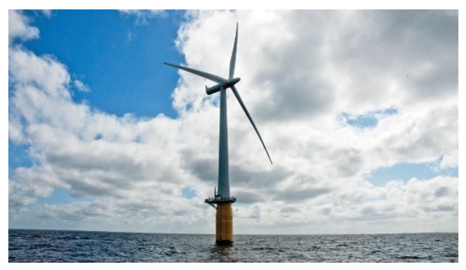
Figure 1. Hywind Demo.
Jmse 10 00542 g001
Figure 2. Hywind Scotland.
Jmse 10 00542 g002
Figure 3. Hywind Tampen.
Jmse 10 00542 g003
Figure 4. A sketch of the coordinate system in FAST.
Jmse 10 00542 g004
Figure 5. Steady-state performance and operation of the IEA 10-MW offshore wind turbine: (a) Generator power vary with the wind speed; (b) Bladed pitch angle varies with the wind speed; (c) Rotor rotation speed varies with the wind speed; (d) Rotor thrust varies with the wind speed.
Jmse 10 00542 g005
Figure 6. Blade pitch angle control with the wind speed varying: (a) Steady-state wind with a pulse; (b) Steady-state wind with a jump.
Jmse 10 00542 g006
Figure 7. Time series of free decay tests: (a) Platform surge motion; (b) Platform heave motion; (c) Platform pitch motion; (d) Platform yaw motion.
Jmse 10 00542 g007
Figure 8. The wave and current information. (a) JONSWAP spectrum of waves; (b) standard current sub-models.
Jmse 10 00542 g008
Figure 9. The turbulence wind generated in TurbSim: (a) Wind speed in hub height; (b) wind speed distributed over the whole wind farm.
Jmse 10 00542 g009
Figure 10. The statistics values of platform responses with or without considered 2nd order wave load: (a) Platform surge motion; (b) platform pitch motion.
Jmse 10 00542 g010
Figure 11. Statistics of platform surge motion response for (a) without current; (b) with current.
Jmse 10 00542 g011
Figure 12. Statistics of platform sway motion response for (a) without current; (b) with current.
Jmse 10 00542 g012
Figure 13. Statistics of platform heave motion response for (a) without current; (b) with current.
Jmse 10 00542 g013
Figure 14. Statistics of platform roll motion response for (a) without current; (b) with current.
Jmse 10 00542 g014
Figure 15. Statistics of platform pitch motion response for (a) without current; (b) with current.
Jmse 10 00542 g015
Figure 16. Statistics of platform yaw motion response for (a) without current; (b) with current.
Jmse 10 00542 g016
Figure 17. Statistics of nacelle acceleration response in x-direction for (a) without current; (b) with current.
Jmse 10 00542 g017
Figure 18. Statistics of nacelle acceleration response in y-direction for (a) without current; (b) with current.
Jmse 10 00542 g018
Figure 19. Statistics of nacelle acceleration response in z-direction for (a) without current; (b) with current.
Jmse 10 00542 g019
Figure 20. Statistics of mooring tension of line 1 for (a) without current; (b) with current.
Jmse 10 00542 g020
Figure 21. Statistics of mooring tension of line 2 for (a) without current; (b) with current.
Jmse 10 00542 g021
Figure 22. Statistics of mooring tension of line 3 for (a) without current; (b) with current.
Jmse 10 00542 g022
Table 1. Key parameters of the IEA 10-MW compared to the DTU 10-MW RWT.
ParameterValueComment
Wind RegimeIEC class 1ASame as DTU 10-MW RWT
Rotor OrientationClockwise rotation—UpwindSame as DTU 10-MW RWT
ControlVariable Speed
Collective Pitch
Same as DTU 10-MW RWT
Cut-in wind speed4 m/sSame as DTU 10-MW RWT
Cut-out wind speed25 m/sSame as DTU 10-MW RWT
Rated wind speed11 m/sOptimized
Rated electrical power10 MWSame as DTU 10-MW RWT
Number of blades3Same as DTU 10-MW RWT
Rotor Diameter198.0Optimized
Airfoil seriesFFA-W3Same as DTU 10-MW RWT
Hub Diameter4.6 mReduced from 5.4 m
Hub Height119.0 mSame as DTU 10-MW RWT
DrivetrainDirect-driveChanged from Medium Speed, Multiple-Stage Gearbox
Minimum Rotor Speed6.0 rpmSame as DTU 10-MW RWT
Maximum Rotor Speed8.68 rpmConstrained by max tip speed
Gearbox RatioN/ADirect-drive
Maximum Tip Speed90.0 m/sSame as DTU 10-MW RWT
Hub Overhang7.1 mSame as DTU 10-MW RWT
Shaft Tilt Angle6.0 deg.Increased from 5 deg
Rotor Precone Angle−4 deg.Increased from −2.5 deg
Blade Prebend6.2 mIncreased from 3.2 m
Blade Mass47,700 kg12% increase from DTU 10-MW RWT
Nacelle Mass542,600 kg-
Tower Mass628,442 kgProvisional, same as DTU 10-MW RWT
Table 2. Operational summary of the IEA 10-MW rotor.
ParameterValueParameterValue
Maximum CP (–)0.49Min Rotor Speed (rpm)6.0
Design tip speed ratio (TSR) (–)10.58Design Pitch (deg)0
Rated Mechanical Power (MW)10.6383Omega Rated (rpm)8.68
Rated Torque (MNm)11.704Max Tip Speed (m/s)90.0
Cut-in Wind Speed (m/s)4.0Cut-out Wind Speed (m/s)25.0
Wind Speed Region II1/2 (m/s)8.5Rated Wind Speed (m/s)10.75
Table 3. Parameters of the spar platform.
ParameterValue
Water depth (m)320
Draft (m)120
Elevation to tower base above SWL (m)10
Depth to top of taper below SWL (m)4
Depth to bottom of taper below SWL (m)12
Diameter above taper (m)8.5
Diameter below taper (m)13
Mass including ballast (kg)1.381 × 10⁷
Displacement (m3)1.53 × 10⁴
Roll moment of inertia about CoG (kg·m2)9.6899 × 10⁹
Pitch moment of inertia about CoG (kg·m2)9.6899 × 10⁹
Yaw moment of inertia about CoG (kg·m2)3.3589 × 10⁸
Vertical CoG below SWL (m)95.5
Vertical CoB below SWL (m)62.3
Table 4. The parameters of the mooring line.
ParameterValue
Radius to anchors (m)855.2
Unstretched mooring line length (m)902.2
Radius to fairleads from spar centerline (m)6.5
Mooring line diameter (m)0.09
Equivalent mooring line mass density (kg/m)245.4
Equivalent mooring line axial stiffness (N)3.84 × 10⁸
Fairlead depth below SWL (m)70.0
Yaw spring stiffness (Nm/rad)1.48 × 108
Table 5. The natural periods of the IEA 10-MW spar type FOWT from decay tests.
DOFs SurgeHeavePitchYaw
Natural period (s)IEA 10-MW103.833.426.38.1
DTU 10-MW 103.331.335.57.6
DNVGL [42]~100 (catenary)25–4025–405–20
Table 6. The parameters of wind-wave combined dynamic load cases.
Return Period (Year)Load Case No.Significant
Wave Height (m)
Wave Peak
Period (s)
Current Speed (m/s)Mean Wind Speed (m/s)Turbine
Status
2LC14.228.701.3819.17operating
LC23.687.1017.40
LC33.439.8313.60
LC43.8110.415.64
LC53.168.7711.00
LC64.3412.218.76
5LC75.1011.11.5120.00operating
LC86.219.8024.92
LC95.948.2021.67
LC105.4713.623.37
LC114.9912.225.15
LC126.4210.022.45
50LC138.9613.52.0034.16parked
LC148.4510.436.78
LC158.139.3040.05
LC168.6916.435.55
LC1710.1613.849.01
LC189.0711.537.79
100LC198.6110.32.2051.80parked
LC208.459.3044.18
LC218.839.9059.29
LC2211.3810.660.02
LC239.3811.441.45
LC2410.7616.370.00
Publisher’s Note: MDPI stays neutral with regard to jurisdictional claims in published maps and institutional affiliations.