Article

Surge Response Analysis of the Serbuoys-TLP Tension Leg Platform under the Action of Wave–Current Coupling

1
State Key Laboratory of Coastal and Offshore Engineering, Dalian University of Technology, Dalian 116024, China
2
Deepwater Engineering Research Centre, Dalian University of Technology, Dalian 116024, China
*
Author to whom correspondence should be addressed.
J. Mar. Sci. Eng. 2022, 10(5), 571; https://doi.org/10.3390/jmse10050571
Submission received: 15 March 2022 / Revised: 20 April 2022 / Accepted: 20 April 2022 / Published: 22 April 2022
(This article belongs to the Section Ocean Engineering)

Abstract

:
A new type of tension leg platform (TLP) connected to a series of buoys (Serbuoys-TLP) has been proven to effectively suppress the surge response of the platform during wave conditions. However, in the complex marine environment, it is more relevant to study its motion response to the action of waves and currents. Considering the tension tendon as a lumped mass model, a DUTMST 2.0 time-domain simulation program was written, based on MATLAB, which can accurately calculate the surge response of the Serbuoys-TLP under wave–current coupling conditions. The suppression efficiency of the Serbuoys-TLP on the surge response was analyzed under different current velocities and wave parameters, and the results showed that the suppression efficiency by the Serbuoys-TLP of surges was higher under the action of waves and currents compared with the action of waves. In addition, the surge response of the platform under the two conditions of wave–current combination and wave–current coupling was also investigated, where wave–current coupling considers the effect of the current’s velocity on the wave period, while the wave–current combination does not consider it, which means that the wave and current are linearly superimposed. The results show that the surge response of the platform will be overestimated without considering the coupling effect of waves and currents. The effect of wave–current coupling has a greater impact on the surge response of the Serbuoys-TLP than that of conventional TLP. Therefore, in the design of new floating structures, the motion performance in response to the effect of wave–current coupling should be paid full attention.

1. Introduction

The focus of energy exploitation is shifting from the land to the ocean, and the tension leg structure is one of the main structural forms in the fields of offshore oil and gas and offshore floating wind power development [1,2]. The process of oil and gas exploitation and wind power generation requires the floating platform to have excellent motion performance. Although tension leg platforms have good motion performance compared with semi-submersible and column platforms, they still produce extreme surge responses to extreme environmental conditions, even leading to damage to the tension tendons [3], and large surge motions by the platform will aggravate the interference of wind turbines in wind farms and reduce the power generation efficiency of wind turbines [4]. Therefore, the motion response of the floating platform is the main consideration in the process of structural design [5,6].
Waves and currents directly affect the motion performance of floating structures [7,8]. There are two ways to consider the action of waves and currents: wave–current combination and wave–current coupling, where wave–current combination means that wave loads and current loads are considered separately, without considering the effect of current velocity on wave encounter frequency, while wave–current coupling considers the effect of current velocity on wave encounter frequency [9,10]. Under wave–current coupling conditions, based on the Doppler effect, the currents affect the wave period and wave steepness, which, in turn, change the motion response of the floating structure [11,12]. Shahat et al. [13] used a wave–current coupling model with the same direction for the wave train and current propagation to conduct parametric research by increasing the wave height and current velocity, and found that the loading ranges of the out-of-plane and in-plane bending moments decreased by up to 36% and 18% when wave–current coupling was considered, relative to the case when it was not considered. Zhao et al. [14] used the method of physical model experiments to investigate the motion response of a tension leg wind turbine under wave and current loads, and the results showed that the action of waves and currents would aggravate the surge response of the platform. Qu et al. [15] investigated the dynamic response of Spar-type wind turbines in the case of distorted waves superimposed on uniform currents, and showed that the peak wave energy spectrum and the motion response of the platform changed significantly with the currents.
A new type of tension leg platform (TLP) connected to a series of buoys (Serbuoys-TLP) can effectively suppress the surge response of the platform [16,17]. At present, this part of the research does not consider the following two conditions: (1) the influence of current load on the offset of the series of buoys and the tension tendons; (2) the coupling of waves and currents. The former case considering the effect of waves and currents on the platform; it can truly reflect the suppression effect of buoys in series on the tension tendons on the motion response of the platform [18,19]. Regarding the latter, currents can lead to changes in the wave period. The study by Xiang et al. [20] showed that the ratio of the wavelength to deck length (or deck width) has a critical effect on the hydrodynamic loads applied to a marine platform. Therefore, the variation in the wave period caused by wave–current coupling leads to a change in the wave load acting on the platform, which can affect the motion response of the floating platform [21,22].
Numerical methods that have been used to investigate the wave–structure interaction in the field of marine engineering are the boundary element method [23], the finite volume method [24], the finite element-based arbitrary Lagrangian–Eulerian method [25], particle-based methods such as the smoothed particle hydrodynamics [26], and hybrid methods such as coupled SPH-DEM [27] and coupled SPH-FEM [28]. However, none of the commercial software tools based on these numerical methods can calculate the motion response of the Serbuoys-TLP because a buoy cannot be hinged on the mooring system in the commercial software packages. Therefore, a program needs to be written to accurately calculate the motion response of the Serbuoys-TLP.
This study used MATLAB to develop a time-domain simulation program named DUTMST 2.0 based on the lumped mass method, which can be used to investigate the surge response of the Serbuoys-TLP under the action of wave–current coupling. The hydrodynamic coefficients and wave forces in the program are calculated by AQWA, in which the hydrodynamic coefficients are calculated on the basis of the boundary element method and the wave forces are calculated on the basis of the diffraction–radiation theory. DUTMST 2.0 obtains the hydrodynamic coefficients and wave forces for calculating the platform’s motion response, and the effects of wave–current coupling on the wave forces are considered in DUTMST 2.0.
Following this section, Section 2 introduces the numerical model and the program’s framework, and the accuracy of the program is verified in Section 3. Section 4 analyzes the effects of current velocity and wave–current coupling on the Serbuoys-TLP’s surge response and suppression efficiency. Finally, the conclusions are drawn in Section 5.

2. Numerical Methods

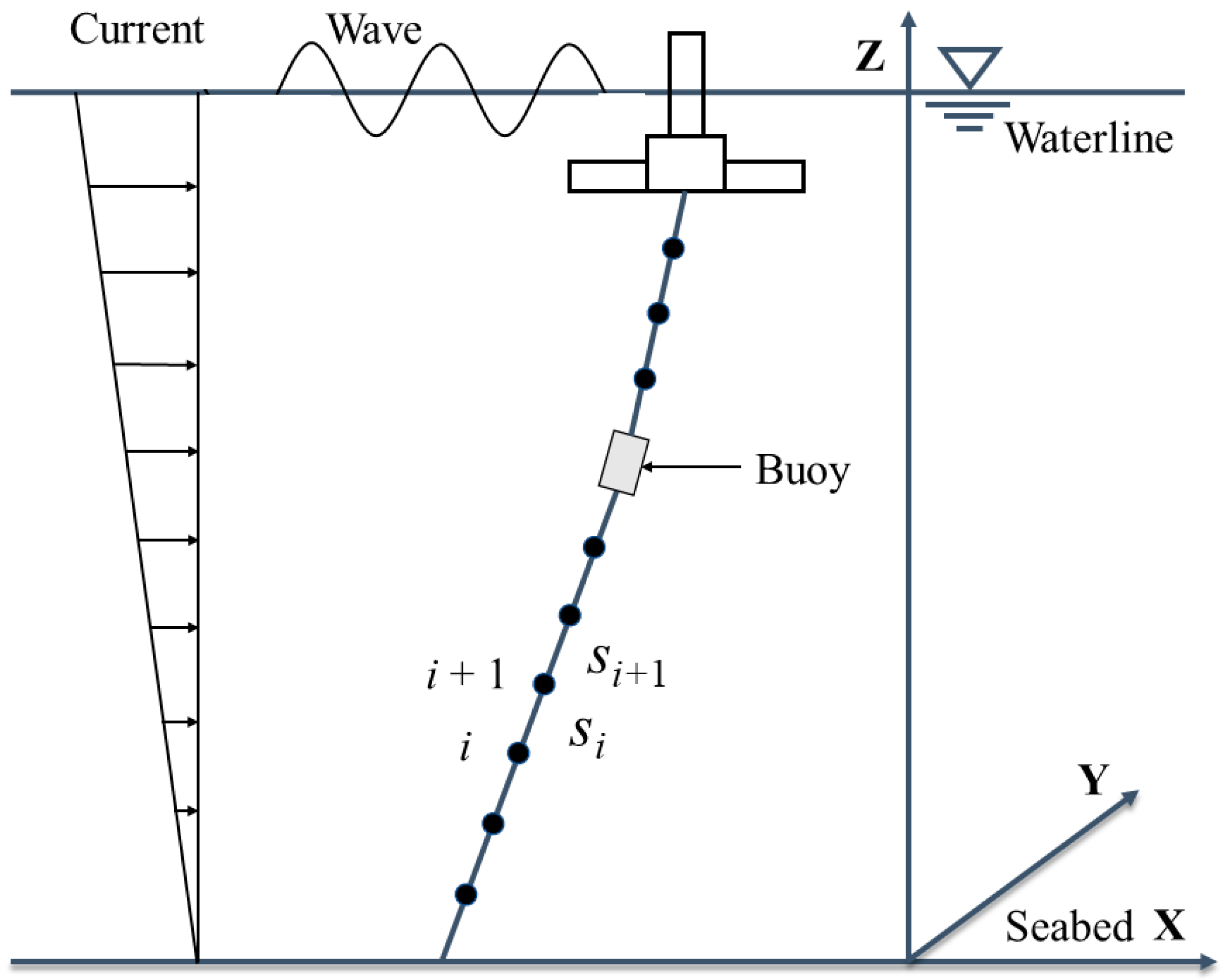
2.1. Numerical Model of the Mooring System

The Serbuoys-TLP consists of a floating platform with a tension leg mooring system with a series of buoys. The connection between the buoy and the tension tendon is articulated [29]. A sketch of the Serbuoys-TLP is shown in Figure 1.
Compared with the massless spring model and the nonlinear beam model, the lumped mass method can fully consider the wave–current load on the floating platform and the tension tendon. It is suitable for the hinged connection between the buoy and the mooring system, so the tendon is simplified to a three-dimensional lumped mass in this method [30,31]. After the model divides the entire tension tendon into n segments, each segment is equivalent to a massless spring, represented by Si (i = 1, …, n), each segment is connected by a mass node, and each node is represented by i (i = 1, …, n). Figure 2 takes a single tendon as an example to show the segmentation of the tendons.
The weight and external load of each segmented element of the tension tendon are equivalently concentrated at the nodes at the ends of the element. The forces on the nodes include the tension of the adjacent segments, the gravity and buoyancy of the segments, and the fluid force. If a buoy is connected between the tension tendons, the gravity, buoyancy, and fluid force on the buoy should also be considered for the corresponding nodes [32].

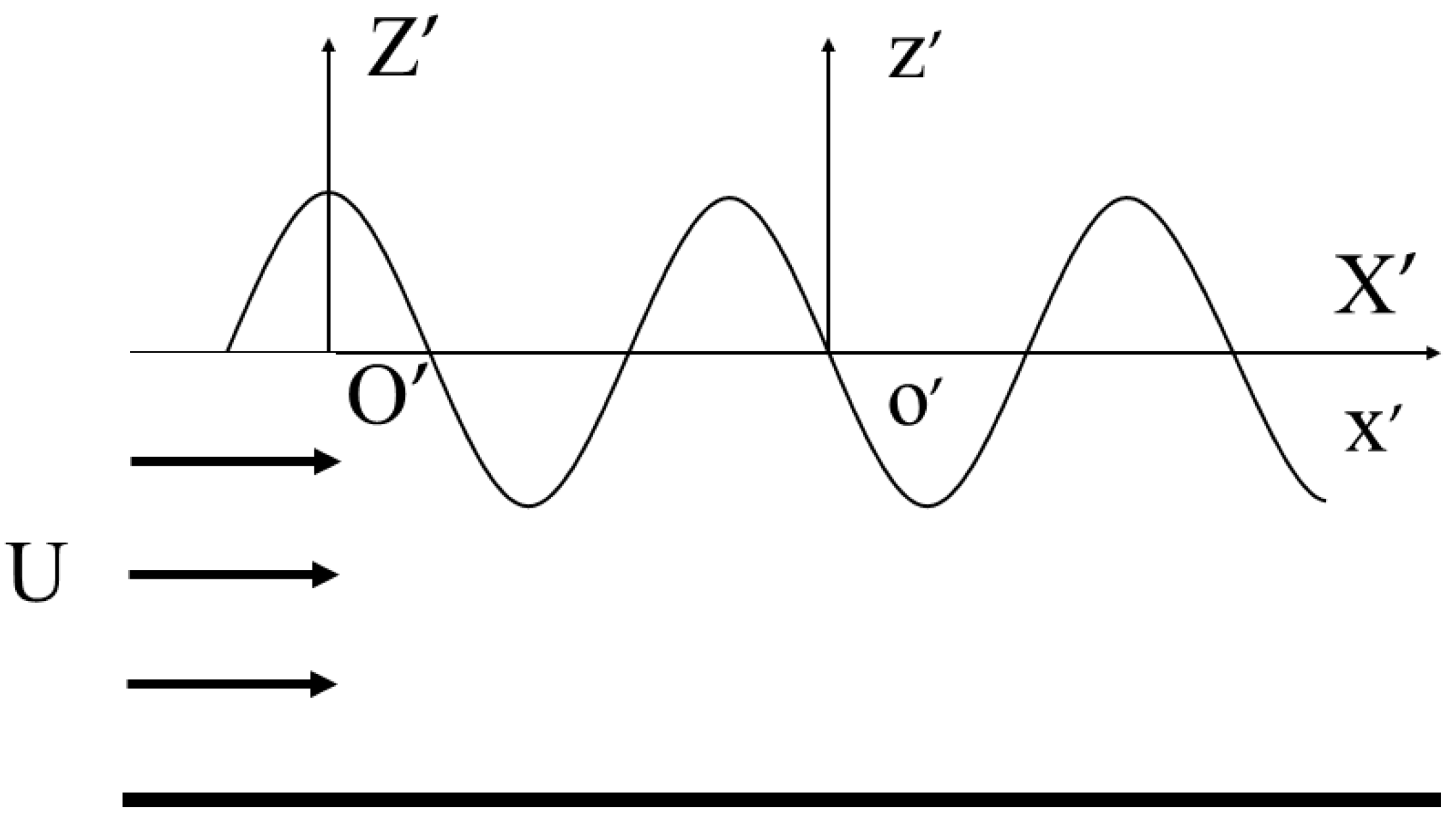
2.2. Wave and Current Loads

The wave-in-deck loads are a very complex research field. Allsop et al. [33] developed a new method for wave-in-deck loads on exposed piers. This new method has been successfully applied to explain failure of bridges and piers during Hurricanes Katrina and Wilma. Istrati et al. [34] revealed the importance of the wave-induced pitching moment and developed simplified load cases that aimed to capture the transient nature of the force and moment. This pitching moment can be especially threatening for the connections and supports of the deck, since it can lead to a concentration of forces in specific components.
In this article, we wanted to study the motion response of the platform under regular sea conditions, so linear regular waves (airy wave theory) were selected. The first-order wave forces under different wave frequencies were calculated by AQWA-LINE. The current forces on the platform and the buoys were calculated by the drag equation and the Morrison equation, respectively. The instantaneous wave and current forces were calculated by the DUTMST 2.0 program.
The wave forces under different frequencies were calculated by Equation (1) [35]:
F ( ω )   = i ω ρ S 0 ϕ I n d S i ω ρ S 0 ϕ d n d S
where F ( ω ) is the wave force at different frequencies; ρ is the seawater density; ω is the frequency of the wave; ϕ I and ϕ d are the incident wave potential with the unit of wave amplitude and the corresponding diffraction wave potential, respectively; n is the unit of the normal vector of the floating body surface.
The instantaneous wave forces are given as:
F ( t )   = A F ( ω ) e i [ ω t + k ( x c o s θ + y s i n θ ) + ψ ]
where F(t) is the instantaneous wave forces, A is the is the wave amplitude, θ is the incident angle of the wave, ψ is the initial phase, (x, y) is the barycentric coordinate of the platform, and F(ω) is the wave forces under different wave frequencies. Both F(ω) and ψ were obtained by AQWA-LINE.
Equation (3) gives the formula of the current forces on the platform, as the bending moment caused by the current forces can be determined by the current forces and the position of the center of gravity:
F c p = 1 2 C d ρ A p V p 2
where Fcp represents the current forces on the platform, Cd is the drag coefficient, ρ is the density of seawater, Ap is the projection of the underwater part of the platform in the direction of the current, and Vp is the relative current velocity.
The variation in the sea current velocity with water depth was modeled by a gradient current model, as shown in Figure 2, with the following expressions:
U ( z ) = z d U ( 0 )
where U(z) is the current velocity at any water depth, U(0) is the current velocity of the sea surface, z is the height from the sea bottom, and d is the water depth.
Barltrop [36] described how under the assumptions of a constant steady current with depth and a constant water depth, a regular wave travelling on the current can be modeled by the established wave theory, but the wave period relative to a stationary observer (or the encounter period due to currents) changes. The regular wave force in the case of wave–current coupling can be calculated by including the encounter frequency in Equation (2).
To illustrate the coupling effect of waves and currents, a coordinate system is established in the new wave and current field, as shown in Figure 3. O’X’Z’ is the spatial fixed coordinate system, and o’x’z’ is the coordinate system of motion with the current. The wavelength and wavenumber are the same in both sets of coordinate systems, and the wave frequency and phase velocity are different.
From the relationship between the wavenumber and the phase velocity in the two coordinate systems, the following relationship can be obtained:
k C a = k C r + k U
ω a = ω r + k U
where k is the wavenumber; C a and ω a are the phase velocity and wave frequency in the fixed coordinate system, respectively; C r and ω r are the phase velocity and wave frequency in the coordinate system of motion with the current, respectively; and U is the current velocity.
According to the relationship shown in Equation (6) and the dispersion relationship of deep-water waves, the wave–current coupling relationship can be derived as follows:
ω t   =   ω 0 ( 1 + ω 0 g U )  
where ω t is the encounter frequency of the wave and ω 0 is the wave frequency in the absence of currents.
The current load on the tension tendon is calculated using Morrison’s equation:
f = 1 2 C d ρ D u | u |   +   1 4 C m ρ π D 2 u
where f is the fluid force on the tension tendon per unit height; Cd and Cm are the drag force coefficient and the inertia force coefficient, respectively, taken here as 0.5 and 1.0; ρ is the density of seawater; D is the diameter of the tension tendon; and u and u ˙ are the velocity and acceleration of the tension tendon per unit height, respectively.
The buoy is a cylinder with a large diameter. Morrison’s equation is no longer applicable to the buoy. The current load on the float is calculated using the API RP 2SK specification via the following equation:
Fcs = Css(CdAf)Vc2
where Fcs is the current load on the buoy; Css is the current coefficient, taken here as 515.62 N·s2/m4; Cd is the drag force coefficient, taken here as 0.5; Af is the vertical projection area of the buoy; and Vc is the velocity of the current at the buoy. It is worth emphasizing that the buoys have motion in the pitch direction, which causes the buoys to rotate [37]. However, preliminary calculations showed that the rotation of the buoys will not exceed 2°, and this can be verified by the results of the following calculations (the ratio of surge to water depth). Therefore, we do not consider changes in Css, Cd, and Af.

2.3. Equations of Motion

The equation of the motion response of the TLP is as follows:
( M p + m p ) x ¨ p   +   C p x ˙ p   +   K p c p   =   F e p   +   F m h   ( h   =   1 , 2 , 3 , 4 )
where Mp and mp are the base mass matrix and the added mass matrix of the TLP, respectively; Cp is the radiation damping matrix; Kp is the hydrostatic stiffness matrix; Fep denotes the external loads other than mooring forces, including wave loads, current loads, and buoyancy; Fmh is the mooring force provided by the h-th tension tendon; and x ¨ i, x ˙ i, and xi are the acceleration, velocity, and displacement at the center of gravity of the structure, respectively, where xp = [xp, yp, zp, rxp, ryp, rzp]T.
The equation of motion for the i-th node can be written as:
( M i + m i ) x ¨ i = F e i + F m i + F m i
where Mi and mi represent the mass matrix and added mass matrix of the i-th node, respectively; Fei represents the external force load on the i-th node, that is, the i-th tendon segment and the half of the (i + 1)-th tendon segment with the current load and buoyancy; Fmi is the tension of the i-th tendon segment; Fmi is the tension of the (i + 1)-th tendon segment; and x ¨ i , x ˙ i , and xi are the acceleration, velocity, and displacement of the node, respectively, where xi = [xi, yi, zi]T.
The equation of motion for the j-th buoy can be written as:
( M j + m j ) x ¨ j   +   C j x ˙ j   =   F e j   +   F m j   +   F m j   ( j   =   1 , 2 , 3 , 4 )
where Mj, mj, and Cj represent the mass matrix, the added mass matrix, and the radiation damping matrix of the j-th buoy, respectively; Fej represents the external force load on the j-th buoy, that is, the current load and buoyancy; Fmj is the tension of the lower tendon segment of the j-th buoy; Fmj is the tension of the upper tendon segment of the j-th buoy; and x ¨ j, x ˙ j, and xj are the acceleration, velocity, and displacement at the center of gravity of the j-th buoy, where xj = [xj, yj, zj, rxj, ryj, rzj]T.
The overall equation of motion of the system can be obtained by combining Equations (10)–(12):
[ M ] x ¨   + [ C ] x ˙   + [ K ] x = [ F ]
where M is the mass matrix of the whole system, including the added mass matrix; C is the damping matrix of the whole system; K is the stiffness matrix of the whole system; F is the load vector of the whole system; and x ¨ , x ˙ , and x are the acceleration, velocity, and displacement at the center of gravity of the floating platform, nodes, and buoys, and their dimensions are related to the number of segments in the tension tendon.

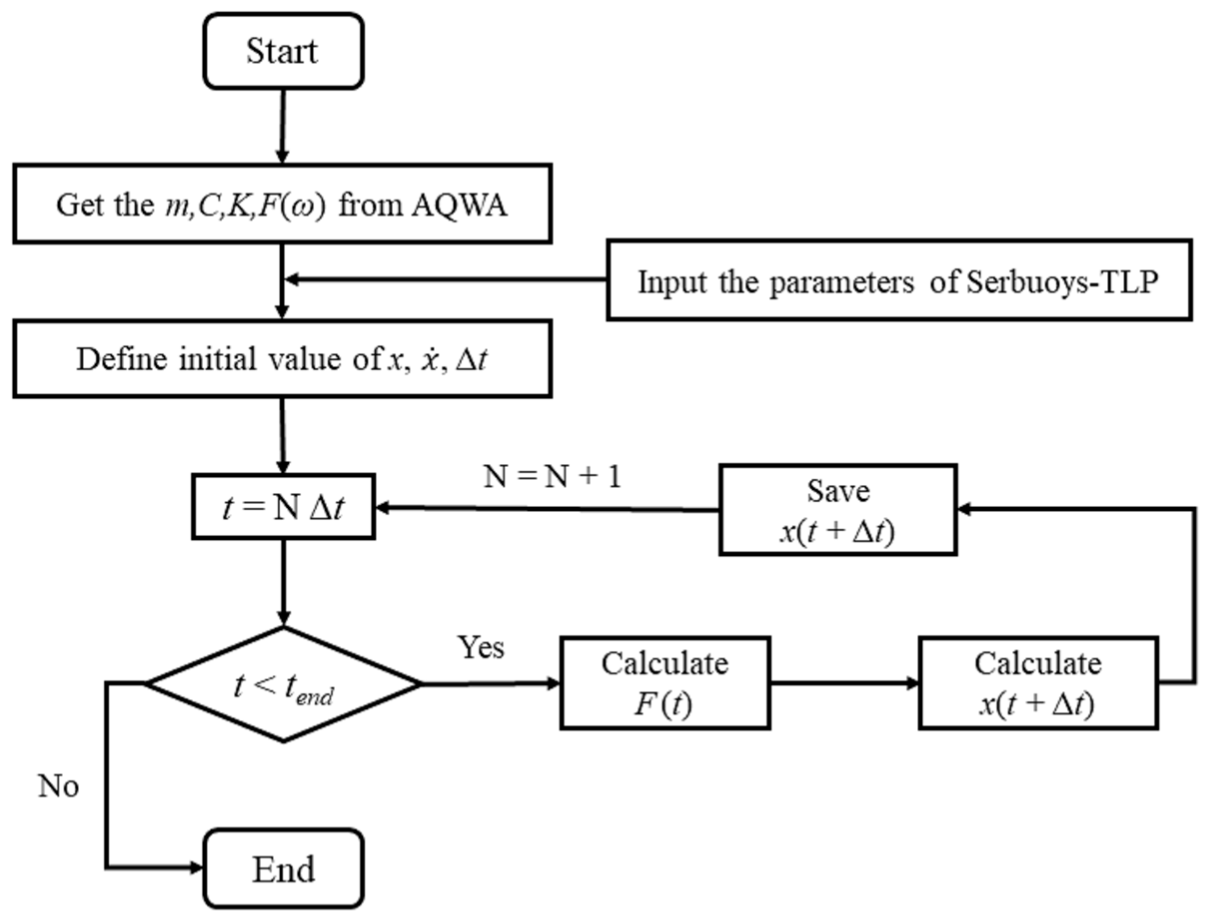
2.4. Solving the Equations of Motion

DUTMST 2.0 uses the fourth-order Runge–Kutta method to solve the differential equation system in Equation (13). The solution flow chart of DUTMST 2.0 is shown in Figure 4. The solution is divided into two parts: firstly, the hydrodynamic information of the floating platform and the buoy calculated by AQWA-LINE, including the added mass, radiation damping, hydrostatic stiffness, and wave force under different frequencies, is obtained through a function written by ourselves and inputted into each matrix of the equations of motion; then the tension vector at this time step is calculated by the real-time position of the floating platform, nodes, and buoy. Iteration is carried out to solve for the position of the structure at the next time step, and these steps are repeated to obtain the motion response of the platform.

3. Validation of the Numerical Model

The numerical validation in this section and the analysis of the results in Section 4 use the same numerical model, in which the Serbuoys-TLP system is applied to the foundation of an offshore wind turbine. Table 1 shows the main parameters of the numerical model.
To confirm that the time domain simulation program DUTMST 2.0 could accurately calculate the surge response of Serbuoys-TLP under the action of wave–current coupling, the convergence of the calculated results of the program concerning the number of tendon segments was verified first. The calculated results of the program were compared with the calculated results of AQWA-NAUT to validate the wave–current coupling load. Finally, compared with the experimental results, the Serbuoys-TLP surge response calculated by the program was validated. Below, the detailed validation process and results are shown.

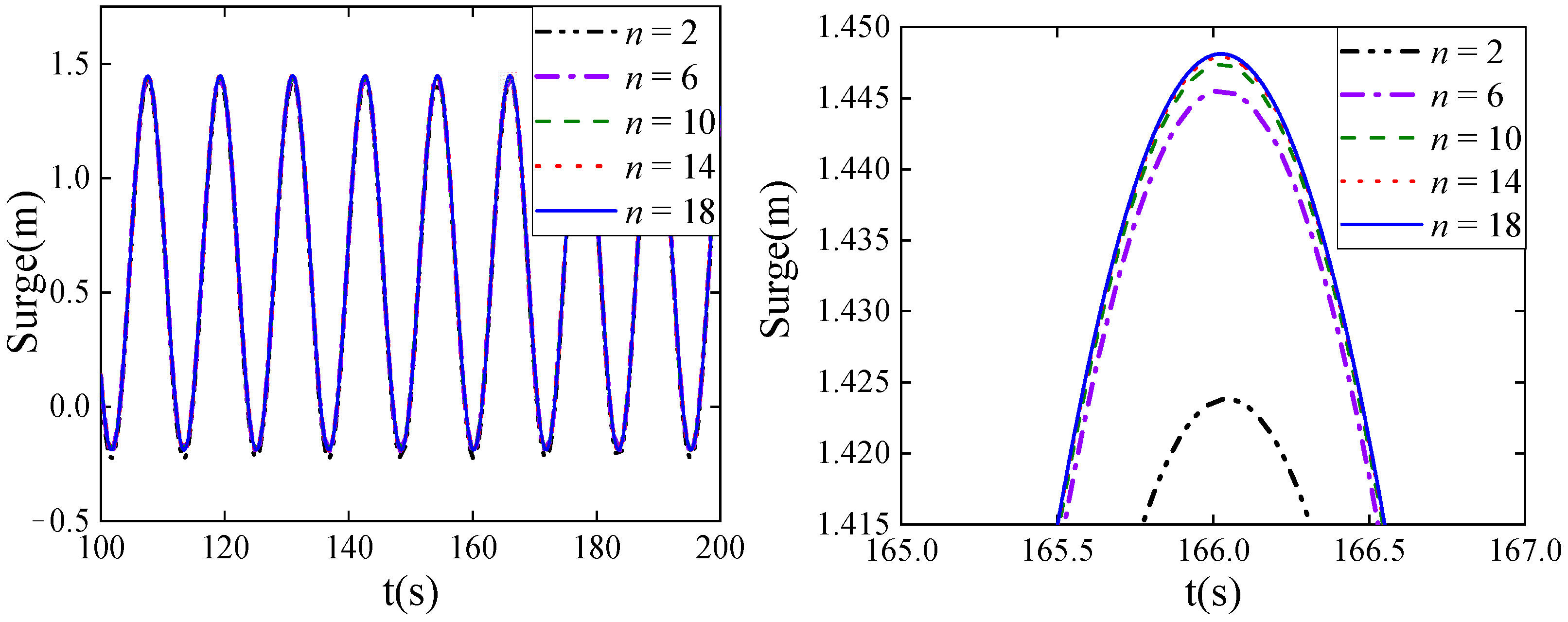
3.1. Verification of Surge Response Convergence

Using the lumped mass method to simulate the tendons needs to consider the influence of the number of tendon segments (n) on the calculated results. As the number of tendon segments increases, the results of calculation gradually converge, but, at the same time, the time cost required for calculation also increases. Table 2 shows the calculation time of DUTMST 2.0 with different numbers of tendon segments. A convergence analysis of the surge response was carried out on a conventional TLP with the following wave parameters: 12 s period, 2 m wave height, 0° wave incidence angle, 0.5 m/s current velocity at the sea surface, and the direction of the current was the same as the wave direction. The tension tendons were divided into 2, 6, 10, 14, and 18 segments, and the surge response of the conventional TLP under these conditions were calculated. The results are shown in Figure 5.
It can be seen from these results that the calculated results tend to converge as the number of tendon segments increases. When the number of tendon segments changed from 2 to 10, the surge response changed by 1.76% and the solving time increased by 1116 s; when the number of tendon segments changed from 10 to 18, the surge response changed by 0.35% and the solving time increased by 2636 s. To consider the accuracy and the time cost required for calculation, the tension tendon was divided into 10 segments in the subsequent numerical simulations.

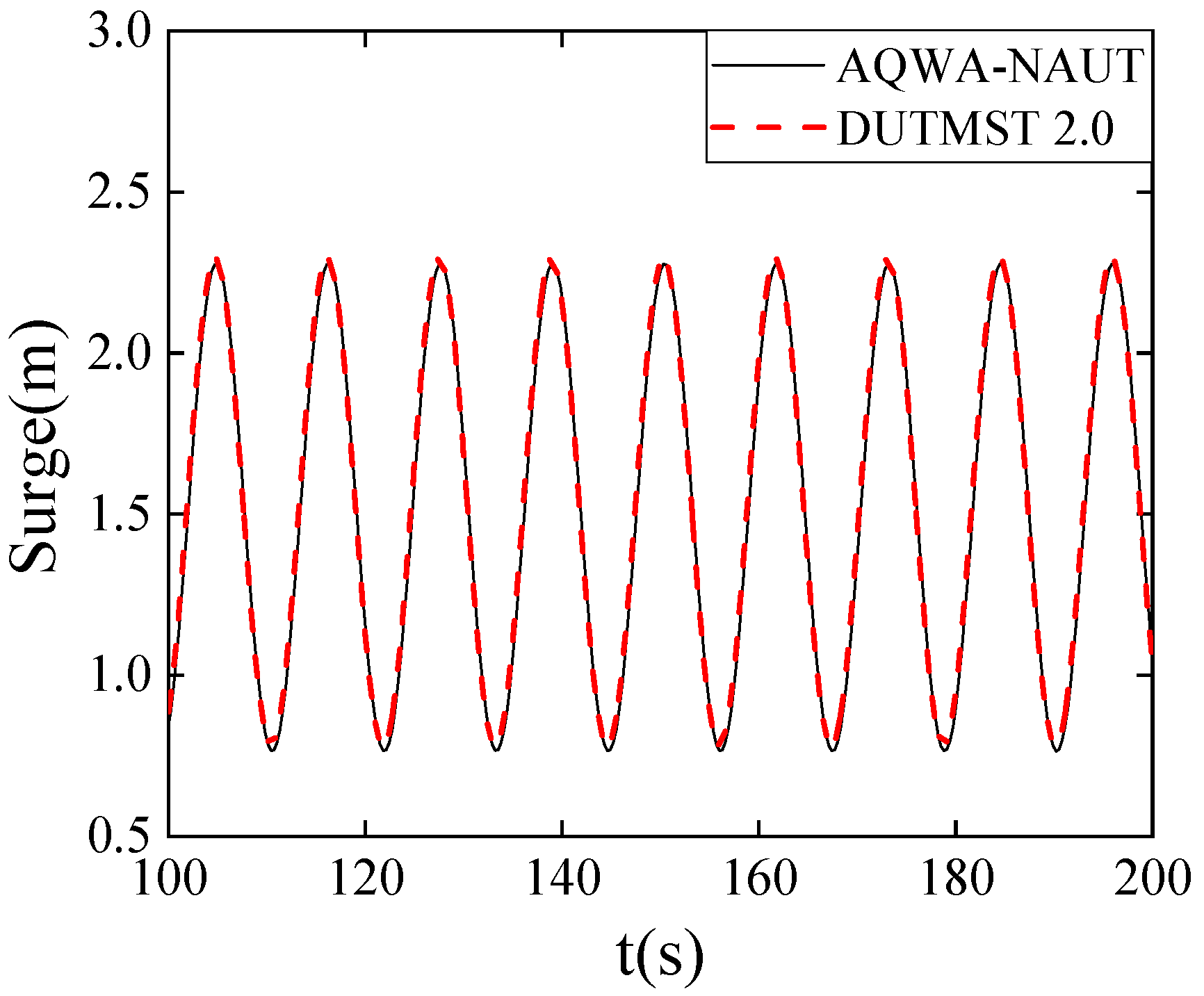
3.2. Validation of Wave–Current Coupling

In DUTMST 2.0, we consider the wave–current coupling and the current load on the tension tendon. AQWA-NAUT can also consider the wave–current coupling and the current load, but it is only applicable for calculations with the conventional TLP but not the Serbuoys-TLP. We used the results calculated for a conventional TLP to verify the accuracy of the DUTMST 2.0 wave–current coupling effect. The wave parameters were a period of 12 s, a wave height of 2 m, a wave incidence angle of 0°, a sea surface current velocity of 1.0 m/s, and the current direction being the same as the wave direction. The results are shown in Figure 6. From a comparison of the results, the calculated results of DUTMST 2.0 and AQWA-NAUT are the same. The hydrodynamic parameters and wave loads of both were calculated by AQWA-LINE, which proves that the wave–current coupling effect considered in DUTMST 2.0 is accurate.

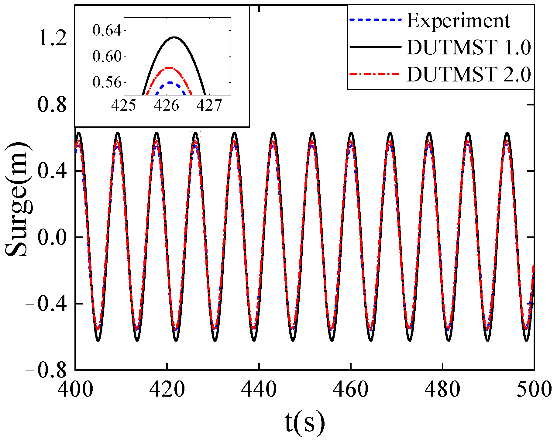
3.3. Validation of the Serbuoys-TLP Surge Response

To confirm that the DUTMST 2.0 program could accurately calculate the surge response of the Serbuoys-TLP, its calculated results were compared with the experimental results of Ren et al. [38], with wave parameters of a period of 8.485 s, a wave height of 3 m, and position of the buoy being 95 m underwater. The results of DUTMST 2.0 and the experimental results are shown in Figure 7, and the results calculated by DUTMST 1.0 based on the massless spring method are also given in this figure. Compared with DUTMST 1.0, the results of DUTMST 2.0 are smaller and in better agreement with the experimental results, indicating that DUTMST 2.0 can calculate the Serbuoys-TLP surge response more accurately. This is as expected, since the concentrated mass method considers the additional mass of the tension tendon and the drag force applied to it, unlike the massless spring method.

4. Results and Discussion

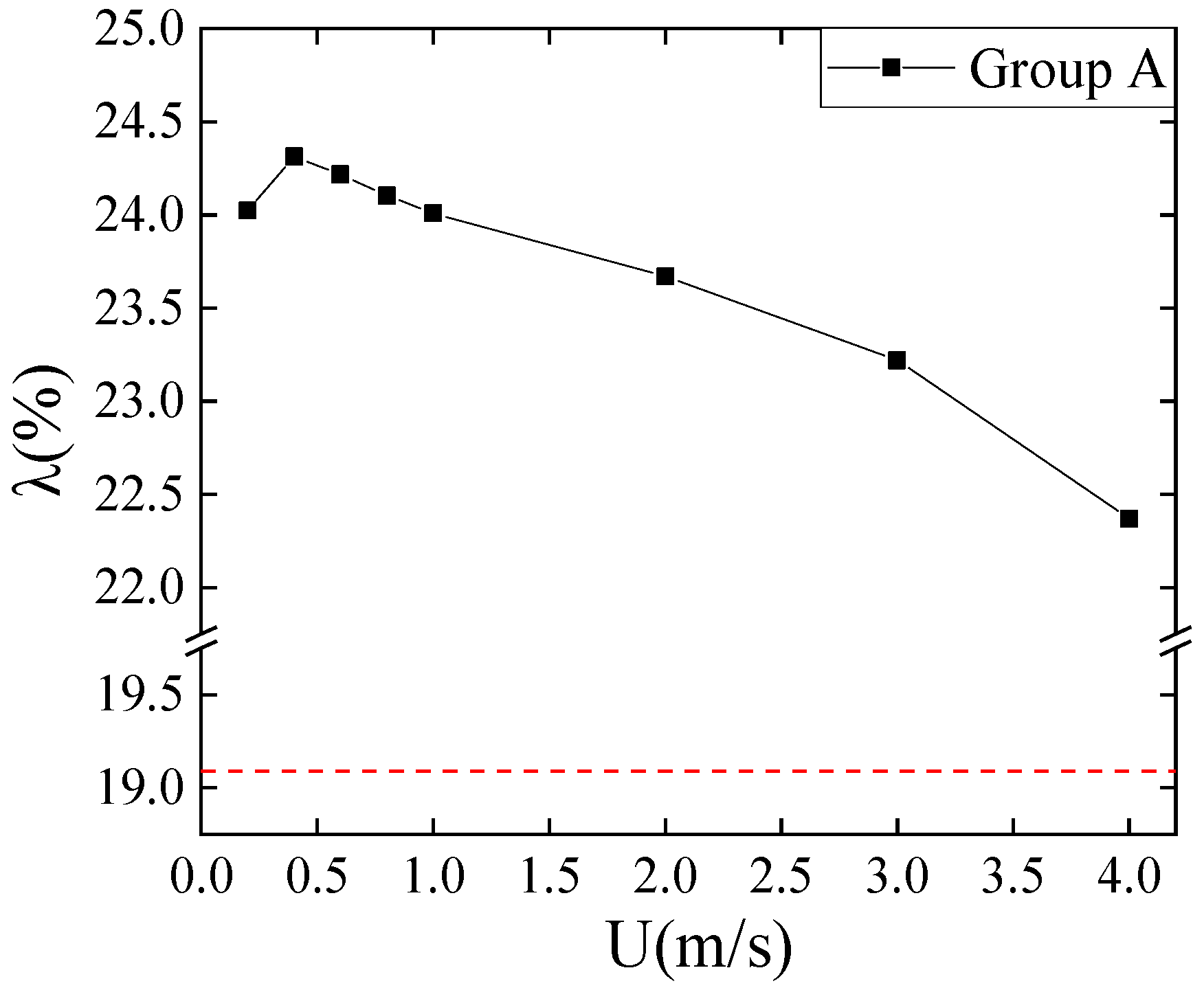
4.1. Effect of Current Velocity on the Surge Response of the Serbuoys-TLP

This study focused on the inhibition effect of the Serbuoys-TLP on the maximum surge displacement of the platform. The study by Van der Meer et al. [39] demonstrated a significant reduction in the wave-induced loads when there is a misalignment between the structure and the wave; therefore, under all operating conditions, the current and the wave are propagated in the same direction, and the angle of incidence of the wave is 0°.
In actual sea conditions, the incident direction of waves does not necessarily coincide with the main axis of the structure. Recent research by Collins et al. [40] showed that an extreme event (storm, hurricane) can generate different wave directions from the usual one at a specific site, and the 3D effects generated in cases where the waves and the main axis of the platform/deck are not aligned have a complex effect because they can reduce the hydrodynamic forces in one direction but generate additional out-of-plane forces, and yaw and roll moments [41]. Therefore, the influence of the angle between the wave and the structure on the platform needs to be studied in the future, because it would allow us to understand more about the suppression efficiency of the Serbuoys-TLP and other degrees of freedom of motion (e.g., sway, yaw, and roll), in order to develop robust motion-suppressing devices for TLP platforms.
The site selection range of the Serbuoys-TLP was the East China Sea and the South China Sea. The common wave conditions and extreme wave conditions in the East China Sea and the South China Sea were measured by buoys [42,43]. Velocity data were obtained from the National Marine Environment Prediction Center.
Numerical simulations of the surge response of the conventional TLP and the Serbuoys-TLP were carried out using DUTMST 2.0 for a total of 32 conditions with different current velocities and wave parameters, and the position of the buoys was 60 m underwater. The current velocity and wave parameters of each working condition are shown in Table 3.
The Serbuoys-TLP can suppress the surge response of the platform. The tandem buoys increase the tension of the lower tendons, which, in turn, increases the mooring stiffness; this has been demonstrated in previous studies [17]. We calculated the suppression efficiency (λ) by the Serbuoys-TLP of the surge under each working condition, which is calculated as follows:
λ = (LcLs)/Lc
where λ is the suppression efficiency by the Serbuoys-TLP of the surge, Lc is the maximum surge displacement of the conventional TLP, and Ls is the maximum surge displacement of the Serbuoys-TLP.
Figure 8 shows the results calculated for Group A, that is, the effect of current velocity on the suppression efficiency λ. The dotted line in the figure represents the surge suppression efficiency of the Serbuoys-TLP under the action of waves, which is about 19%. Under the action of wave–current coupling, the suppression efficiency λ was about 24%. The excellent surge performance of the Serbuoys-TLP was better reflected under the action of waves and currents, which is because the current made the equilibrium position of the platform shift, and the Serbuoys-TLP not only reduced the amplitude of oscillation of the platform about the equilibrium position but also reduced the offset of the equilibrium position. As the current velocity increased from 0 to 0.4 m/s, the suppression effect of the Serbuoys-TLP on the offset of the equilibrium position started to manifest, causing the suppression efficiency λ to increase; as the current velocity continued to increase, the proportion of the increased mooring stiffness of the buoy to the overall mooring stiffness decreased, resulting in a slow decrease in the suppression efficiency λ.
The results calculated for Group B conditions are shown in Figure 9, which gives the variation in the suppression efficiency λ with wave height for U = 0 m/s and U = 1 m/s. For U = 0 m/s, the suppression efficiency λ decreased with increasing wave height, and for U = 1 m/s, the suppression efficiency λ increased with increasing wave height. To investigate the reason for the difference between the two laws, the time domain curves of the conventional TLP’s and the Serbuoys-TLP’s surge responses under wave conditions of H = 10 m and T = 9 s are given in Figure 10. In Figure 10a, it can be seen that the equilibrium position of the conventional TLP shifted by 0.055 m and that of the Serbuoys-TLP shifted by 0.164 m under wave action. The buoy on the tendon makes the drag force on the Serbuoys-TLP greater than that on the conventional TLP, and the shift in the equilibrium position increases with an increase in wave height. The greater equilibrium position offset of the Serbuoys-TLP weakens its suppressing effect on the oscillation’s amplitude, which leads to a decrease in the suppression efficiency λ with an increase in the wave height in the case of wave action. As shown in Figure 10b, the initial offset of the equilibrium position is caused by the current under the action of wave–current coupling, and the increase in the wave height makes the wave load on the platform larger and thus increases the offset of the equilibrium position. The suppression efficiency λ increases as shown in Figure 9, indicating that the Serbuoys-TLP can better suppress the surge response of the platform under conditions of current and a larger wave height.
By calculating the surge response of the conventional TLP and the Serbuoys-TLP under Group C conditions, the variation law of the suppression efficiency λ with different wave periods can be given, as shown in Figure 11, from which we see that the suppression efficiency λ decreases with an increase in the wave period in the cases of both wave action and wave–current coupling action. Under the action of waves, the wave period increases from 8 s to 12 s, and the suppression efficiency λ decreases from 21.54% to 12.82%, with a reduction of 8.72%; under the action of wave–current coupling, the wave period increases from 8 s to 12 s, and the suppression efficiency λ decreases from 25.25% to 21.47%, with a reduction of 3.78%. The amplitude of the suppression efficiency λ decreases with an increase in the wave period under wave coupling, and was smaller than that under wave action. The presence of currents makes the platform subject to wave loading at the encounter frequency, and it is known from Equation (7) that the encounter frequency of waves is larger than the wave frequency in the absence of currents, so the reduction in suppression efficiency λ is smaller in the case of wave–current coupling. Compared with the case of wave action, the Serbuoys-TLP can better reflect the superiority of its motion performance under low-frequency wave conditions in the case of wave–current coupling.

4.2. Effect of Whether the Waves and Currents Are Coupled on the Surge

The surge time domain curves of the conventional TLP and the Serbuoys-TLP under wave–current coupling and combined wave–current action are given in Figure 12. Disregarding the wave–current coupling effect will make the motion period of the surge larger and will overestimate the maximum surge displacement. η is the effect of whether the waves and currents are coupled on the surge, which is calculated as follows:
η = (LnLo)/Ln
where η is the effect of whether the waves and currents are coupled on the surge, Ln is the maximum surge displacement of the platform under the combined action of waves and currents, and Lo is the maximum surge displacement of the platform under the action of wave-current coupling.
The effect of whether the waves and currents are coupled on the surge of the conventional TLP and the Serbuoys-TLP with different current velocities, wave heights, and wave periods are given in Figure 13. It can be seen from the figure that the effect of whether the waves and currents are coupled on the surge of the conventional TLP and the Serbuoys-TLP is consistent with the variation in current velocity, wave height, and wave period, and the effect of wave–current coupling on the surge response of the Serbuoys-TLP is greater. In Figure 13a–c, the effect of whether the waves and currents are coupled on the surge of the platform increases with an increase in the current velocity and then decreases; it increases with an increase in the wave height, but the magnitude of the increase becomes smaller. It also increases with an increase in the wave period, and the magnitude of the increase is the largest when the wave period increases from 9 s to 10 s. These findings suggest that the wave coupling effect should be considered in the design of a TLP, which would allow designers to not overestimate the surge response of the platform. Even at a high current velocity (greater than 2 m/s), wave–current coupling has little effect on the motion response of the platform, but at a common current velocity (0–1 m/s), this value can still reach 5%. For the Serbuoys-TLP, the wave–current coupling effect has a greater impact on the motion response and should be considered for a more economical design.
The conclusions of this study were all reached under the action of linear regular waves, without considering nonlinearity and breaking waves. At present, extreme climates are frequent, and future research should focus on the motion response of the Serbuoys-TLP under the action of breaking waves. Although the Serbuoys-TLP increases the mooring stiffness and still has an inhibitory effect on the motion response, its regularity under breaking waves may be different. Breaking waves are dominated by significant turbulence effects and air entrapment, and they apply hydrodynamic loads on marine decks that are different from those of unbroken waves [44]. For breaking waves, considering the effect of air, the difficulty is the simulation of multiphase flow, because the compression of the gas phase is also considered, which also makes the pressure difficult to predict [45].

5. Conclusions

In this study, the time domain simulation program DUTMST 2.0 written in MATLAB could accurately calculate the surge response of the Serbuoys-TLP under the action of wave–current coupling. Through an analysis of the surge response of the Serbuoys-TLP under different working conditions, the following conclusions can be drawn:
  • The surge suppression efficiency (λ) of the Serbuoys-TLP was 19.09% under pure wave action, while the suppression efficiency λ was about 24% under wave–current coupling condition and the suppression efficiency λ increased rapidly and then decreased slowly as the current velocity increased.
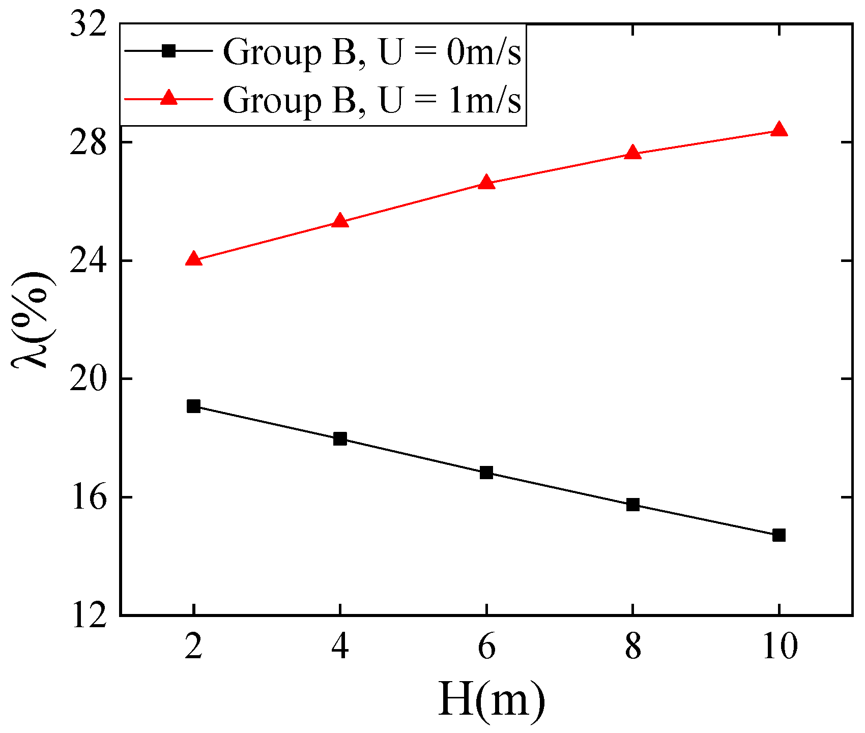
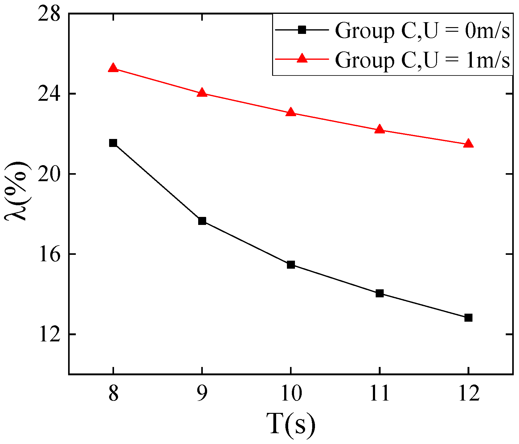
  • Under pure wave conditions, a negative correlation was found between the suppression efficiency λ and wave height or period. Under wave–current coupling conditions, something different was found: first, the suppression efficiency λ increased as the wave height became larger; second, the percentage of the decrease in λ with a varying period was smaller than that under pure wave conditions As the period increased, this percentage increased from 4.46% to 8.12%.
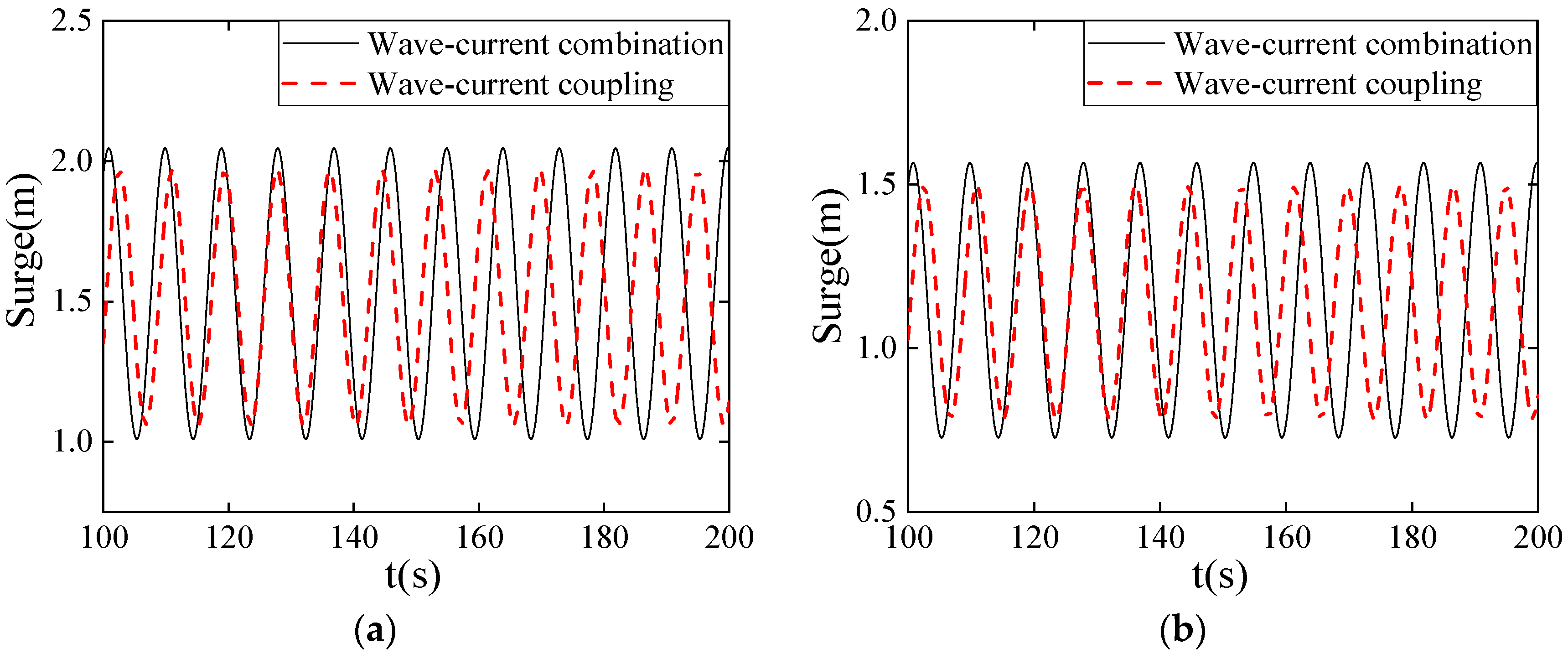
  • If the coupling effect between waves and currents is not considered, the surge response of a TLP will be overestimated. The effect of whether the wave and current are coupled was greater on the surge response of the Serbuoys-TLP, being 1% higher than the effect on that of the conventional TLP.
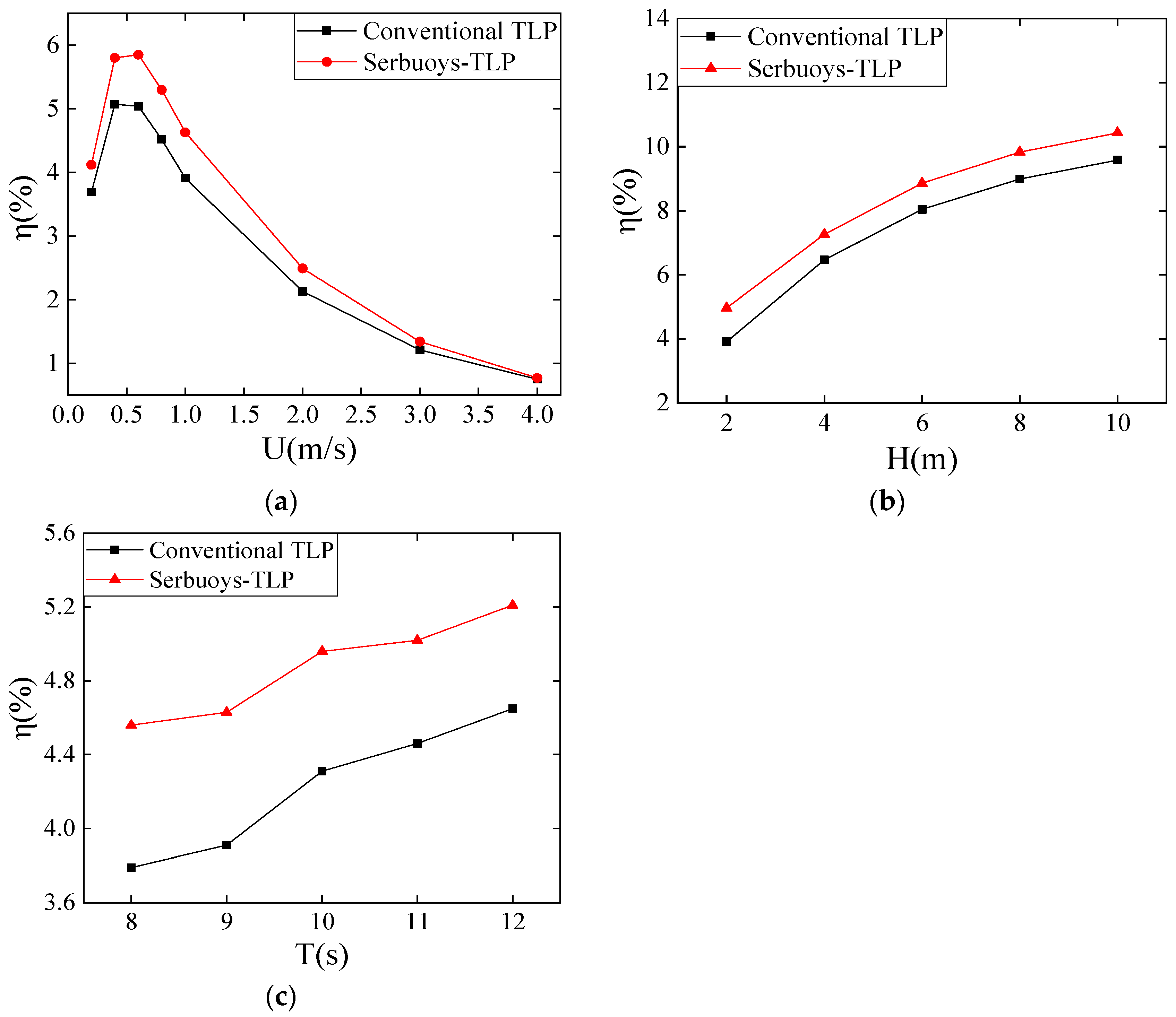
  • The effect of whether the waves and currents are coupled on the surge of the Serbuoys-TLP (η) increased and then decreased with an increase in current velocity, up to a maximum of 5.85%. η increased from 4.96% to 10.43% with an increase in wave height. η increased from 4.56% to 5.21% with an increase in wave period.
The research presented here proves that the Serbuoys-TLP can effectively suppress the surge response of the platform under the action of waves and current, thus broadening the application scenarios of the Serbuoys-TLP. The response of the surge suppression efficiency of the Serbuoys-TLP under different current velocities and wave parameters was analyzed and can provide guidance for practical engineering applications. In future work, we will add wind loads to the program to study the suppression effect of the Serbuoys-TLP on the motion response under the coupled effect of wind, waves, and current.

Author Contributions

Conceptualization, Z.M. and G.Z.; methodology, Z.M. and Z.L.; software, Z.L.; formal analysis, Z.L.; investigation, Z.L. and J.L.; resources, J.L.; writing—original draft preparation, Z.L. and J.L.; and writing—review and editing, Z.M., G.Z. and Z.L. All authors have read and agreed to the published version of the manuscript.

Funding

This research received no external funding.

Institutional Review Board Statement

Not applicable.

Informed Consent Statement

Not applicable.

Data Availability Statement

Not applicable.

Conflicts of Interest

The authors declare no conflict of interest.

References

  1. Myhr, A.; Bjerkseter, C.; Ågotnes, A.; Nygaard, T.A. Levelsed cost of energy for offshore floating wind turbines in a life cycle perspective. Renew. Energy 2014, 66, 714–728. [Google Scholar] [CrossRef] [Green Version]
  2. Chandrasekaran, S.; Nagavinothini, R. Dynamic analyses and preliminary design of offshore triceratops in ultra-deep waters. Innov. Infrastruct. Solut 2018, 3, 16. [Google Scholar] [CrossRef]
  3. Ren, Y.; Vengatesan, V.; Shi, W. Dynamic Analysis of a Multi-column TLP Floating Offshore Wind Turbine with Tendon Failure Scenarios. Ocean Eng. 2022, 245, 110472. [Google Scholar] [CrossRef]
  4. Huang, Z.; Ding, Q.; Li, C. Study on Dynamic Response of Floating Wind Turbine with a New Type of Tension Leg Platform. J. Eng. Therm. Energy Power 2019, 34, 156–163. [Google Scholar]
  5. Bangga, G.; Guma, G.; Lutz, T.; Krämer, E. Numerical simulations of a large offshore wind turbine exposed to turbulent inflow conditions. Wind Eng. 2018, 42, 88–96. [Google Scholar] [CrossRef]
  6. Song, J.; Lim, H.C. Study of floating wind turbine with modified tension leg platform placed in regular waves. Energies 2019, 12, 703. [Google Scholar] [CrossRef] [Green Version]
  7. Chen, L.; Basu, B. Wave-current interaction effects on structural responses of floating offshore wind turbines. Wind Energy 2019, 22, 327–339. [Google Scholar] [CrossRef]
  8. Hong, J.S.; Moon, J.H.; Kim, T.; Cho, I.H.; Choi, J.; Park, J.Y. Response of wave energy to tidal currents in the western sea of Jeju Island, Korea. Renew. Energy 2021, 172, 564–573. [Google Scholar] [CrossRef]
  9. Tabeshpour, M.R.; Shoghi, R. Perturbation nonlinear response of tension leg platform under regular wave excitation. J. Mar. Sci. Technol. 2018, 23, 132–140. [Google Scholar] [CrossRef]
  10. Tabeshpour, M.R.; Hedayatpour, R. Analytical investigation of nonlinear heave-coupled response of tension leg platform. Proc. Inst. Mech. Eng. Part M J. Eng. Marit. Environ. 2018, 233, 699–713. [Google Scholar] [CrossRef]
  11. Silva, M.C.; Vitola, M.A.; Esperanc, P.T.T.; Sphaier, S.H.; Levi, C.A. Numerical simulations of wave-current flow in an ocean basin. Appl. Ocean Res. 2016, 61, 32–41. [Google Scholar] [CrossRef]
  12. Xie, T.; Zhao, S.Z.; Perrie, W.; Fang, H.; Yu, W.J.; He, Y.J. Electromagnetic backscattering from one-dimensional drifting fractal sea surface I: Wave-current coupled model. Chin. Phys. B 2016, 25, 214–222. [Google Scholar] [CrossRef]
  13. El-Shahat, S.A.; Li, G.; Fu, L. Investigation of wave-current interaction for a tidal current turbine. Energy 2021, 227, 120377. [Google Scholar] [CrossRef]
  14. Zhao, Y.; She, X.; He, Y.; Yang, J.; Peng, T.; Kou, Y. Experimental study on new multi-column tension-leg-type floating wind turbine. China Ocean Eng. 2018, 32, 123–131. [Google Scholar] [CrossRef]
  15. Qu, X.; Li, Y.; Tang, Y.; Hu, Z.; Zhang, P.; Yin, T. Dynamic response of spar-type floating offshore wind turbine in freak wave considering the wave-current interaction effect. Appl. Ocean Res. 2020, 100, 102178. [Google Scholar] [CrossRef]
  16. Ma, Z.; Wang, S.; Wang, Y.; Ren, N.; Zhai, G. Experimental and numerical study on the multi-body coupling dynamic response of a novel serbuoys-tlp wind turbine. Ocean Eng. 2019, 192, 106570. [Google Scholar] [CrossRef]
  17. Ma, Z.; Ren, N.; Wang, Y.; Wang, S.; Shi, W.; Zhai, G. A comprehensive study on the serbuoys offshore wind tension leg platform coupling dynamic response under typical operational conditions. Energies 2019, 12, 2067. [Google Scholar] [CrossRef] [Green Version]
  18. Oyejobi, D.O.; Jameel, M.; Sulong, N.H.R.; Khan, N.B. Investigation of tendon dynamics effects on tension leg platform response in random seas. Proc. Inst. Mech. Eng. Part M J. Eng. Marit. Environ. 2018, 233, 1082–1102. [Google Scholar] [CrossRef]
  19. Ishihara, T.; Liu, Y. Dynamic response analysis of a semi-submersible floating wind turbine in combined wave and current conditions using advanced hydrodynamic models. Energies 2020, 13, 5820. [Google Scholar] [CrossRef]
  20. Xiang, T.; Istrati, D. Assessment of extreme wave impact on coastal decks with different geometries via the arbitrary lagrangian-eulerian method. J. Mar. Sci. Eng. 2021, 9, 1342. [Google Scholar] [CrossRef]
  21. Osuna, P.; Monbaliu, J. Wave-current interaction in the Southern North Sea. J. Mar. Syst. 2004, 52, 65–87. [Google Scholar] [CrossRef]
  22. Ye, J.H.; Jeng, D.S. Response of porous seabed to nature loadings: Waves and currents. J. Eng. Mech. 2012, 138, 601–613. [Google Scholar] [CrossRef]
  23. Belibassakis, K.A. A boundary element method for the hydrodynamic analysis of floating bodies in variable bathymetry regions. Eng. Anal. Bound. Elem. 2008, 32, 796–810. [Google Scholar] [CrossRef]
  24. Tsui, Y.Y.; Huang, Y.C.; Huang, C.L.; Lin, S.W. A finite-volume-based approach for dynamic fluid-structure interaction. Numer. Heat Tranf. B Fundam. 2013, 64, 326–349. [Google Scholar] [CrossRef]
  25. Xiang, T.; Istrati, D.; Yim, S.C.; Buckle, L.G. Tsunami loads on a representative coastal bridge deck: Experimental study and validation of design equations. J. Waterw. Port Coast. Ocean Eng. 2020, 146, 04020022. [Google Scholar] [CrossRef]
  26. Westphalen, J.; Greaves, D.M.; Raby, A.; Hu, Z.; Causon, D.; Mingham, C.; Omidvar, P.; Stansby, P.; Rogers, B.D. Investigation of wave-structure interaction using state of the art CFD techniques. Open J. Fluid Dyn. 2014, 4, 18. [Google Scholar] [CrossRef] [Green Version]
  27. Ren, B.; Jin, Z.; Gao, R.; Wang, Y.; Xu, Z. SPH-DEM modeling of the hydraulic stability of 2D blocks on a slope. J. Waterw. Port Coast. Ocean Eng. 2014, 140, 04014022. [Google Scholar] [CrossRef]
  28. Hasanpour, A.; Istrati, D.; Buckle, L. Coupled SPH–FEM modeling of tsunami-borne large debris flow and impact on coastal structures. J. Mar. Sci. Eng. 2021, 9, 1068. [Google Scholar] [CrossRef]
  29. Palm, J.; Eskilsson, C. Mooring systems with submerged buoys: Influence of buoy geometry and modelling fidelity. Appl. Ocean Res. 2020, 102, 102302. [Google Scholar] [CrossRef]
  30. Lee, H.H.; Wang, P.W. Analytical solution on the surge motion of tension-leg twin platform structural systems. Ocean Eng. 2000, 27, 393–415. [Google Scholar] [CrossRef]
  31. Lee, H.H.; Wang, W.S. Analytical solution on the dragged surge vibration of tension leg platforms (TLPS) with wave large body and small body multi-interactions. J. Sound Vibr. 2001, 248, 533–556. [Google Scholar] [CrossRef]
  32. Chai, Y.T.; Varyani, K.S.; Barltrop, N.D.P. Three-dimensional lump-mass formulation of a catenary riser with bending, torsion and irregular seabed interaction effect. Ocean Eng. 2002, 29, 1503–1525. [Google Scholar] [CrossRef]
  33. Allsop, W.; Cuomo, C.; Tirindelli, M. New prediction method for wave-in-deck loads on exposed piers/jetties/bridges. Coast. Eng. 2007, 5, 4482–4493. [Google Scholar]
  34. Istrati, D.; Buckle, L.; Lomonaco, P.; Yim, S. Deciphering the Tsunami Wave Impact and Associated Connection Forces in Open-Girder Coastal Bridges. J. Mar. Sci. Eng. 2018, 6, 148. [Google Scholar] [CrossRef] [Green Version]
  35. Yeung, R.W. Added mass and damping of a vertical cylinder in finite-depth waters. Appl. Ocean Res. 1981, 4, 119–133. [Google Scholar] [CrossRef]
  36. Barltrop, N.D.P. Floating Structures: A Guide for Design and Analysis, 1st ed.; CMPT: London, UK, 1998.
  37. Mavrakos, S.A.; Chatjigeorgiou, J. Dynamic behavior of deep water mooring lines with submerged buoys. Comput. Struct. 1997, 64, 815–839. [Google Scholar] [CrossRef]
  38. Ren, N.; Li, Y.; Ou, J. The wind-wave tunnel test of a tension-leg platform type floating offshore wind turbine. J. Renew. Sustain. Energy 2012, 4, 63117. [Google Scholar] [CrossRef]
  39. Van der Meer, M.; Briganti, R.; Zanuttigh, B.; Wang, B. Wave transmission and reflection at low-crested structures: Design formulae, oblique wave attack and spectral change. Coast. Eng. 2005, 52, 915–929. [Google Scholar] [CrossRef]
  40. Collins, C.O.; Potter, H.; Lund, B.; Tamura, H.; Graber, H.C. Directional Wave Spectra Observed During Intense Tropical Cyclones. J. Geophys. Res. Oceans 2018, 123, 773–793. [Google Scholar] [CrossRef]
  41. Istrati, D.; Buckle, L. Tsunami Loads on Straight and Skewed Bridges—Part 2: Numerical Investigation and Design Recommendations; Dept. of Transportation. Research Section: Salem, OR, USA, 2021. [Google Scholar]
  42. Jiang, B.; Ding, J.; Wu, H.; Jiang, X.; Ye, Q.; Zhang, J. Wave energy resources assessment along Bohai Sea, Yellow Sea and East China Sea. Acta Energ. Sol. Sin. 2017, 38, 6. [Google Scholar]
  43. Zheng, C.; Zhou, L. Wave climate and wave energy analysis of the South China Sea in recent 10 years. Acta Energ. Sol. Sin. 2012, 33, 1349–1356. [Google Scholar]
  44. Istrati, D.; Buckle, L. Role of Trapped Air on the Tsunami-Induced Transient Loads and Response of Coastal Bridges. Geosciences 2019, 9, 191. [Google Scholar] [CrossRef] [Green Version]
  45. Zhai, G.; Zhou, T.; Ma, Z.; Ren, N.; Chen, J.; Teh, H. Comparison of impulsive wave forces on a semi-submerged platform deck, with and without columns and considering air compressibility effects, under regular wave actions. Eng. Appl. Comp. Fluid Mech. 2021, 15, 1932–1953. [Google Scholar] [CrossRef]
Figure 1. Sketch of the Serbuoys-TLP: (a) front view; (b) top view (units: m).
Jmse 10 00571 g001
Figure 2. Sketch of the tension tendons’ segmentation.
Jmse 10 00571 g002
Figure 3. Coupling effect of waves and currents.
Jmse 10 00571 g003
Figure 4. Solution flow chart of DUTMST 2.0.
Jmse 10 00571 g004
Figure 5. Calculated results of DUTMST 2.0 with different numbers of tendon segments.
Jmse 10 00571 g005
Figure 6. Surge response of the conventional TLP to the action of wave–current coupling.
Jmse 10 00571 g006
Figure 7. Surge response of the Serbuoys-TLP to wave action.
Jmse 10 00571 g007
Figure 8. Surge suppression efficiency of the Serbuoys-TLP under different current velocities.
Jmse 10 00571 g008
Figure 9. Surge suppression efficiency of the Serbuoys-TLP under different wave heights.
Jmse 10 00571 g009
Figure 10. Surge response of the conventional TLP and the Serbuoys-TLP: (a) U = 0 m/s, H = 10 m, T = 9 s; (b) U = 1 m/s, H = 10 m, T = 9 s.
Jmse 10 00571 g010
Figure 11. Surge suppression efficiency of the Serbuoys-TLP under different wave periods.
Jmse 10 00571 g011
Figure 12. Surge response of the TLPs under the action of waves and currents: (a) the conventional TLP; (b) the Serbuoys-TLP.
Jmse 10 00571 g012
Figure 13. Effect of whether the waves and currents are coupled on the surge of a TLP. (a) The effect of current velocity on η; (b) the effect of wave height on η; (c) the effect of wave period on η.
Jmse 10 00571 g013
Table 1. Main parameters of the wind turbine, the Serbuoys-TLP, and the buoys.
ParameterValueParameterValue
NREL 5MWBlade and nacelle mass, kg3.5 × 105Tower height, m90
Wind turbineTower mass, kg3.5 × 105
Serbuoys-TLPPlatform draft, m30Water depth, m170
Buoyancy, N5.11 × 107Pre-tension, N2.94 × 107
Ixx/Iyy/Izz/ × 109 kg·m24.5/4.5/0.5Tendon diameter, m1.2
Tendon density, kg·m−37850Elastic modulus, Pa2.11 × 1011
Spoke design, mL = 20; A = 4 × 4Water density, kg·m−31025
BuoyBuoy height, m10Buoy radius, m5.65
Displacement, kg4 × 250,000
Table 2. Calculation time of DUTMST 2.0 with different numbers of tendon segments.
Number of Tendon Segments (n)Time to Solve (s)
228
6453
101144
142330
183780
Table 3. Current velocity and regular wave conditions.
GroupsCurrent Velocity (U)/ms−1Wave Height (H)/mWave Period (T)/s
Group A (6)0; 0.2; 0.4; 0.6; 0.8; 1; 2; 3; 429
Group B (10)0; 12; 4; 6; 8; 109
Group C (10)0; 128; 9; 10; 11; 12
Publisher’s Note: MDPI stays neutral with regard to jurisdictional claims in published maps and institutional affiliations.

