Article

A Novel Integrated Gliding and Flapping Propulsion Biomimetic Manta-Ray Robot

1
School of Marine Science and Technology, Northwestern Polytechnical University, Xi’an 710072, China
2
Unmanned Vehicle Innovation Center, Ningbo Institute of NPU, Ningbo 315103, China
3
Key Laboratory of Unmanned Underwater Vehicle Technology of Ministry of Industry and Information Technology, Xi’an 710072, China
*
Author to whom correspondence should be addressed.
J. Mar. Sci. Eng. 2022, 10(7), 924; https://doi.org/10.3390/jmse10070924
Submission received: 13 June 2022 / Revised: 28 June 2022 / Accepted: 30 June 2022 / Published: 4 July 2022
(This article belongs to the Special Issue Frontiers in Deep-Sea Equipment and Technology)

Abstract

:
Bionic underwater robots are the intersection of biology and robotics; they have the advantages of propulsion efficiency and maneuverability. A novel vehicle that combines a gliding and flapping propulsion inspired by a manta ray is presented in this article. The outstanding character of the robot is that its integrated maneuverable flapping propulsion relies on two bionic flexible pectoral fins and long-range efficient gliding propulsion, which is based on a buoyancy-adjustment system and a mass-adjustment system. We designed the biomimetic manta ray robot and analyzed the principle of the gliding and flapping system in this paper. The gliding propulsion capability and the flapping propulsion performance are verified through gliding and swimming experiments. In conclusion, the designed bionic manta robot provides a platform with practical application capabilities in marine environment detection, concealed reconnaissance, and aquaculture.

1. Introduction

Natural selection has ensured that the mechanical systems that have evolved in underwater creatures are highly efficient concerning each species’ habitat and mode of life [1,2,3,4]. Gray’s research in 1936 found that the energy consumed by the dolphin’s body during high-speed swimming is far less than that of dragging a corresponding rigid model [5]. Creatures such as dolphins and fish have evolved a superior motion performance to that of artificial propeller-propelled vehicles [6]. Since the world’s first bionic fish ROBOTUNA was made public in 1994 [7], scientists have conducted extensive research on bionic robotic fish [8,9]. Rus and Tolley [8] discussed developments in the emerging field of soft robotics, inspired by a range of biological systems. Faheem Ahmed et al. [10] provide a detailed overview of the development of soft robotics. A multi-material bio-inspired octopus robot for synchronous underwater swimming and a soft bioinspired frog robot (EXPOG) capable of synchronous underwater swimming were presented in [11,12]. A comprehensive survey of current research in biomimetic underwater robots and soft robots was presented by Wang et al. [9,13]. It is supposed that biomimetic underwater vehicles will play an essential role in aquatic environment exploration and resource utilization.
According to their different propulsion styles, fish are classified into body and caudal fin (BCF) and median and paired pectoral fins (MPF) types [14]. Biomimetic robot fish can also be distinguished according to this method. Fish that use the BCF propulsion mode have an advantage in cruise speed and acceleration, while the MPF propulsion mode fish have better performance in terms of maneuverability and stability. The authors of [15,16] reviewed BCF biomimetic fish in detail. Yu et al. [17] realized a leaping robotic dolphin in 2019. Compared with BCF fish, the MPF fish-like creature the manta ray has attracted enough focus for its maneuverability and load capacity [18]. Bi et al. have developed several biomimetic cownose ray robot fish with oscillating and flexible pectoral fins and achieved various manta-like movements using bionic control methods since 2007 [19,20,21,22,23,24]. The BOSS Manta Ray is an autonomous underwater bionic vehicle that the Festo company has been developing since 2013 within the framework of the Bionic Observation and Survey System project. It has two propulsion modes: active life-like wing propulsion and hydro-jet propulsion [25,26,27]. Wang et al. [28] designed a micro-biomimetic manta ray robot fish actuated by shape memory alloy (SMA) wire, that could swim with good stability and stealth. An underwater glider with bionic wings controlled by two operating modes was proposed. Several experiments were conducted in the coastal area to analyze the propulsive characteristics of the bionic wings in sea trials [29]. The prototype of a biomimetic underwater vehicle inspired by the manta ray was presented, and the locomotion patterns of the manta ray were implemented by using a model of artificial central pattern generators (CPG) [30,31].
From the above analysis, we concluded that most of the manta-like robotic fish mentioned are in the theoretical research stage, and only a few have natural environment operational experience. The Festo’s BOSS Manta [25] has good stability and maneuverability. It can achieve flapping propulsion and pump jet stability, but its load capacity may be smaller than the prototype with a load capacity of 20 kg in this article. The glider [29] with manta ray fins has an advantage in sliding, and the pectoral fins are used as an auxiliary propulsion method. The glider could realize the flapping propulsion, but the flapping propulsion performance is not specified. The experiment’s results [32,33] achieved reasonable control accuracy, but their test environment was in a pool, where the water was still without any current disturbance. While in our present work, the gliding and swimming experiments were carried out in a lake with complicated interference from the unknown flowing water. A comparison of the bionic underwater robots is presented in Table 1 to show the advantages of the proposed manta robot.
The main innovation of this paper is the realization of a bionic platform with practical application capability. (a) The proposed manta-like robot has a payload capacity of more than 20 kg, so it can take a greater load to carry out complex underwater missions than miniature robots. (b) The designed robot has two propulsion modes: gliding and flapping based on flexible fins, so it could realize efficient gliding over long-distances and make high maneuvering turns to avoid obstacles.
We organized the rest of this paper as below. In the second part, the manta ray robot shape, the overall structure, the gliding system, and the flapping system are described in detail. We explain the experiments and results in the third section. In the discussion part, the limitations and future directions are analyzed. Finally, we conclude our present work.

2. The Design of the Manta Ray Robot

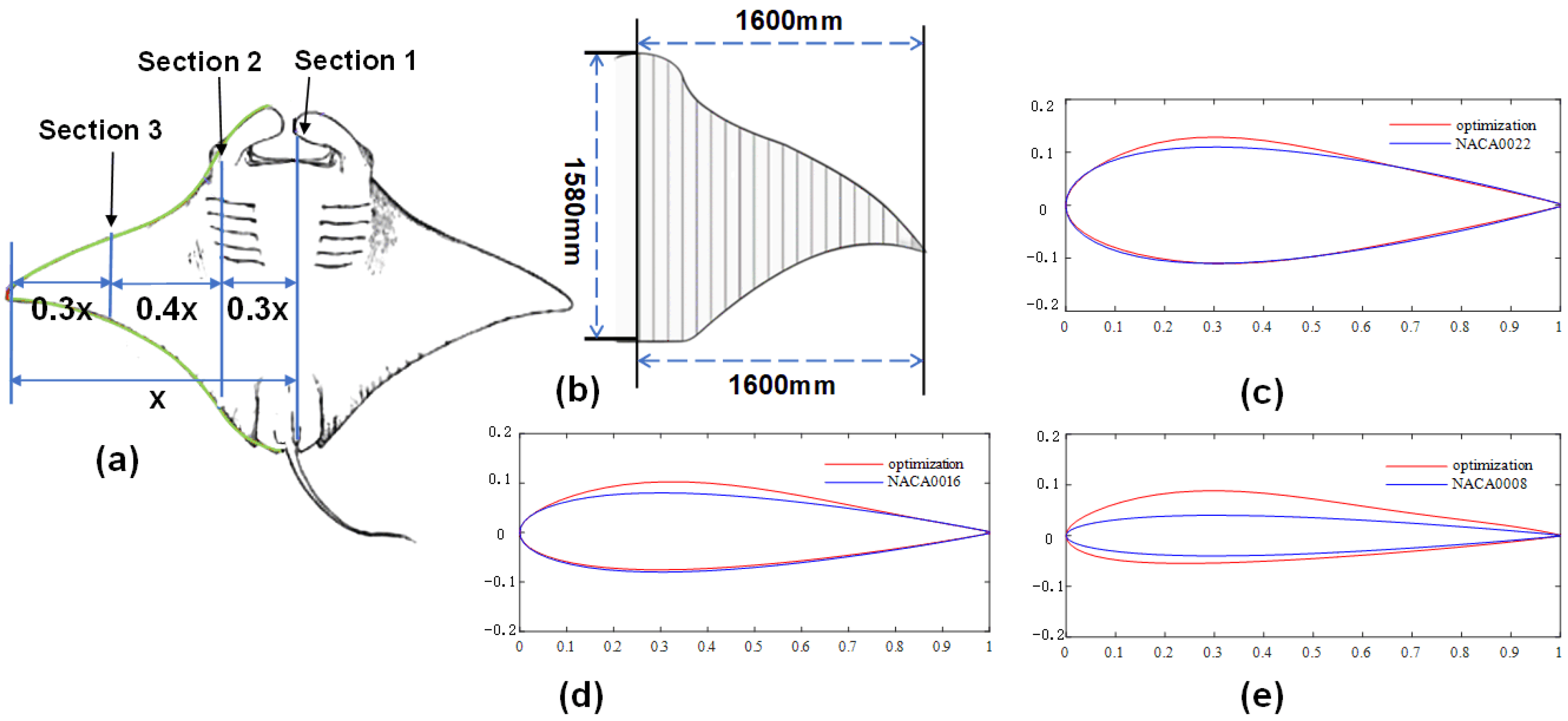
2.1. The Shape Design of the Manta Ray Robot

The bionic shape features provide good hydrodynamic characteristics for the bionic robot. The shape design mainly completes the outline design of the main body of the submersible and the calculation of its hydrodynamic parameters to meet the requirements of a high lift-to-drag ratio. Fish have evolved to form a perfect shape, so their contours are the preferred imitation object when engineers want to design a bionic robotic fish. We show the biological characteristics of the bionic manta ray in Figure 1a and the contour of the bionic submersible obtained by fitting in Figure 1b. The aspect ratio is about 2:1, similar to the real manta ray. The shape design ignores the manta ray’s cephalic fins, eyelids, and eye gills and only includes pectoral fins and body parts.
To obtain a better bionic effect, meet the streamlined characteristics of the bionic submersible, and approximate the original shape of the manta ray, we applied the NACA00 series airfoils as the basic airfoils and the two-dimensional airfoil optimization system to optimize them. We used the optimized airfoils as the section shape of the bionic submersible, which was the initial condition for the realization of the three-dimensional physical model of the submersible. According to the shape characteristics of the manta ray, we extracted three key sections, shown in Figure 1a, for the airfoils’ optimization. NACA0022, NACA0016, and NACA0008 were selected as the basic airfoils, shown in Figure 1c–e. The optimized airfoils were used as the section shape to complete the three-dimensional modeling of the prototype.

2.2. The Structure Design of the Manta Ray Robot

As shown in Figure 2a, the overall structure of the autonomous deformation bionic soft body submersible adopted a non-pressure truss structure. We installed the internal equipment and electronic devices in independent pressure-resistant and sealed cabins. The overall design is divided into five parts: the main body, the left and right solid wings, and the left and right flapping wings. The central body part includes the main frame, the buoyancy-adjustment system, the mass-adjustment system, the navigation control system, the security system, the satellite communication system, and the power system. The left and right solid wings include a wing frame, a magnesium seawater battery, and a flapping wing mechanism. The soft flapping fin comprises a biomimetic skeletal structure built by a linkage mechanism and an airfoil frame, and a flexible skin wraps the exterior. We show the actual prototype in Figure 2b.

2.3. The Gliding System Design of the Manta Ray Robot

This section introduces the gliding motion of the manta ray robot and the gliding system’s design.

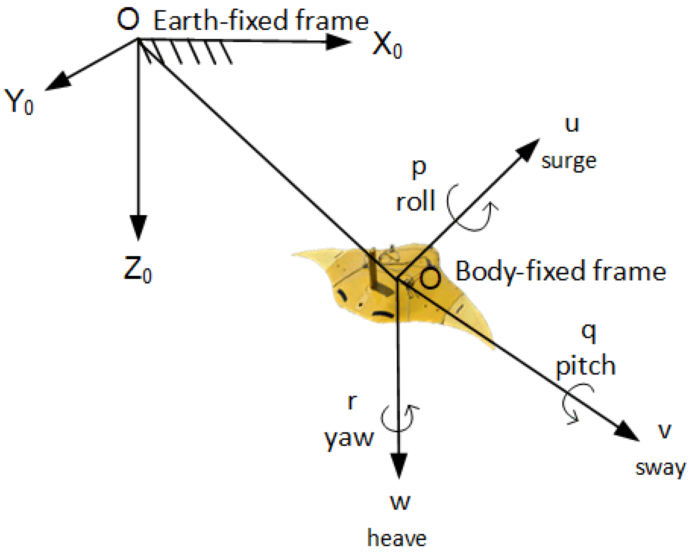
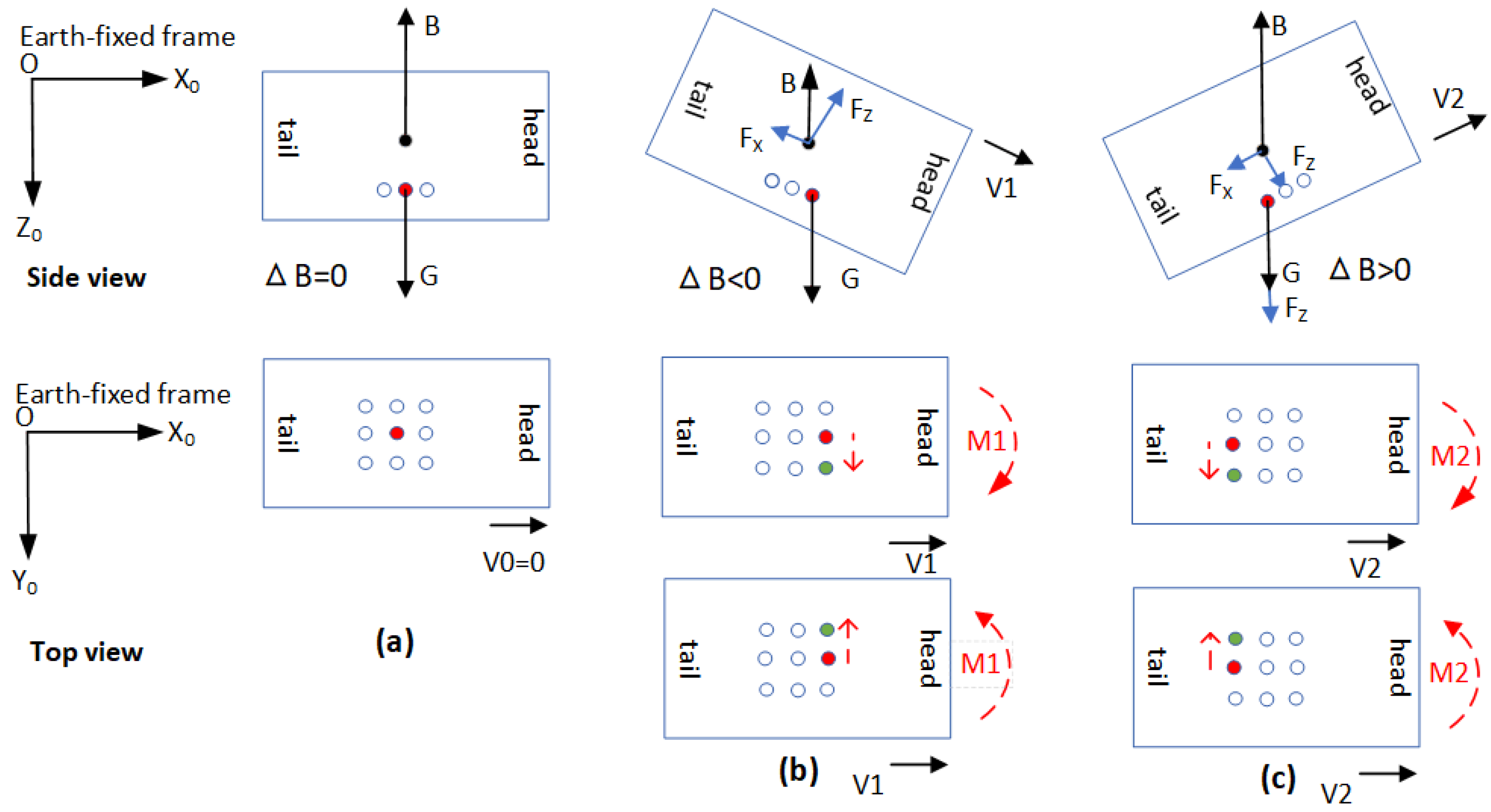
2.3.1. The Gliding Motion Analysis of the Manta Ray Robot

To describe the motions of the manta ray robot in six degrees of freedom (DOF), we used six independent coordinates (Table 2) to represent the position and attitude. The six DOF movements of the prototype were surge, roll, and heave, which refer to the longitudinal, sideways, and vertical displacements, and roll, pitch, and yaw, which describe the rotations about the longitudinal, transverse, and vertical axes. The general motions of the manta ray robot could be described by the flowing vectors: η = [ x , y , z , φ , θ , ψ ] T , υ = [ u , v , w , p , q , r ] T , and τ = [ X , Y , Z , K , M , N ] T , where η denotes the earth-fixed position and attitude vector, υ denotes the body-fixed linear and angular velocity vector, and τ is used to describe the forces and moments acting on the robot in the body-fixed frame. We picture the body-fixed and inertial reference frames in Figure 3.
Assuming that the robot moves in an ideal fluid with a constant speed of V0, ignoring the water’s viscous and inertial forces, the motion equations of the robot in the vertical plane can be simplified as follows:
m u ˙ = ( G B ) sin θ F X
m w ˙ = ( G B ) cos θ F Z
B = B 0 + Δ B
G = G 0 + Δ G
F X = 1 2 ρ u 2 S x C x
F Z = 1 2 ρ w 2 S y C y
where G , G 0 ,   and   Δ G denote the gravity of the robot, the gravity of the robot without the mass block, and the gravity of the mass block; B , B 0 , and   Δ B denote the buoyancy, the buoyancy equal to the robot gravity, the adjustable amount of the buoyancy system; F X and F Z are used to describe the fluid resistances in the x-axis and the z-axis; m and ρ denote the mass of the robot and the density of the water; S x   and   S y are used to describe the maximum transverse cross-sectional area and the maximum longitudinal cross-sectional area; and C x ,   C y denote the hydrodynamic parameters. The force analysis diagram of the robot gliding up and down is shown in Figure 4.

2.3.2. The Buoyancy-Adjustment System Design

As an essential part of the gliding system of the manta ray robot, the buoyancy-adjustment system plays a vital role in the depth control, attitude adjustment, compensation for carrier buoyancy, and load changes. The primary function of the buoyancy-adjustment system is to adjust the buoyancy of the watercraft itself, and the purpose is to realize the functions of the watercraft’s floating and diving by changing its buoyancy. The system adopts the form of a piston hydraulic cylinder, and the outline structure is shown in Figure 2c. The system comprises an inner and outer oil cavity. The piston rod connects the inner and outer pistons to realize synchronous movement. The outer oil cavity and the internal oil cavity are connected through the external oil pipeline, and the control function of the power control system is used to adjust the outer oil cavity. The volume distribution ratio of hydraulic oil in the inner oil cavity realizes the system’s overall drainage volume change control, and finally realizes the buoyancy adjustment control.

2.3.3. The Mass-Adjustment System Design

The function of the buoyancy-adjustment system is to provide power to the robot to make the vehicle ascend and descend. In contrast, the mass-adjustment system controls the vehicle’s attitude while gliding up and down. As shown in Figure 2e, the mass-adjustment system comprises a lead block group, a transmission gear group, a pitch motor, a roll motor, a ball screw, a ball guide rail, a distance sensor, an attitude sensor, and four limit switches. When the mass-adjustment system changes the pitch angle of the robot, the pitch control motor will drive the mass block to move on the linear ball guide forward and backward, and the centroid position of the vehicle will be adjusted axially. The ranging sensor measures the axial position of the mass block. When the mass-adjustment system changes the roll angle of the robot, the roll motor will drive the mass block to rotate around the radial axis, and the centroid position of the vehicle will adjust radially. The SBG sensor measures the axial position of the mass block. The limit switches at both ends prevent the mass block from moving beyond the limit positions.
The function of the center of mass mechanism is to adjust the pitch angle and roll angle of the robotic fish by moving the mass block. When the robotic fish glides in the water, the flow velocity of the fluid flowing through the upper and lower surfaces of the robotic fish is different due to the other areas of the upper and lower surfaces of the robotic fish. According to Bernoulli’s equation, there will be a pressure difference between the upper and lower surfaces of the robotic fish, equivalent to a pitching moment on the robotic fish. We illustrate it in two cases, when the roll angle of the robotic fish is zero, this moment is equivalent to a pitching moment; when the roll angle of the robotic fish is not equal to zero, the component of this moment will generate a yaw moment, which makes the mechanical fish change course. As shown in Figure 4, when the rolling mechanism controls the mass block to rotate in the radial direction, adjusting the position of the center of gravity of the prototype and changing the roll angle, then the purpose of adjusting the heading angle by controlling the roll motor can be achieved.

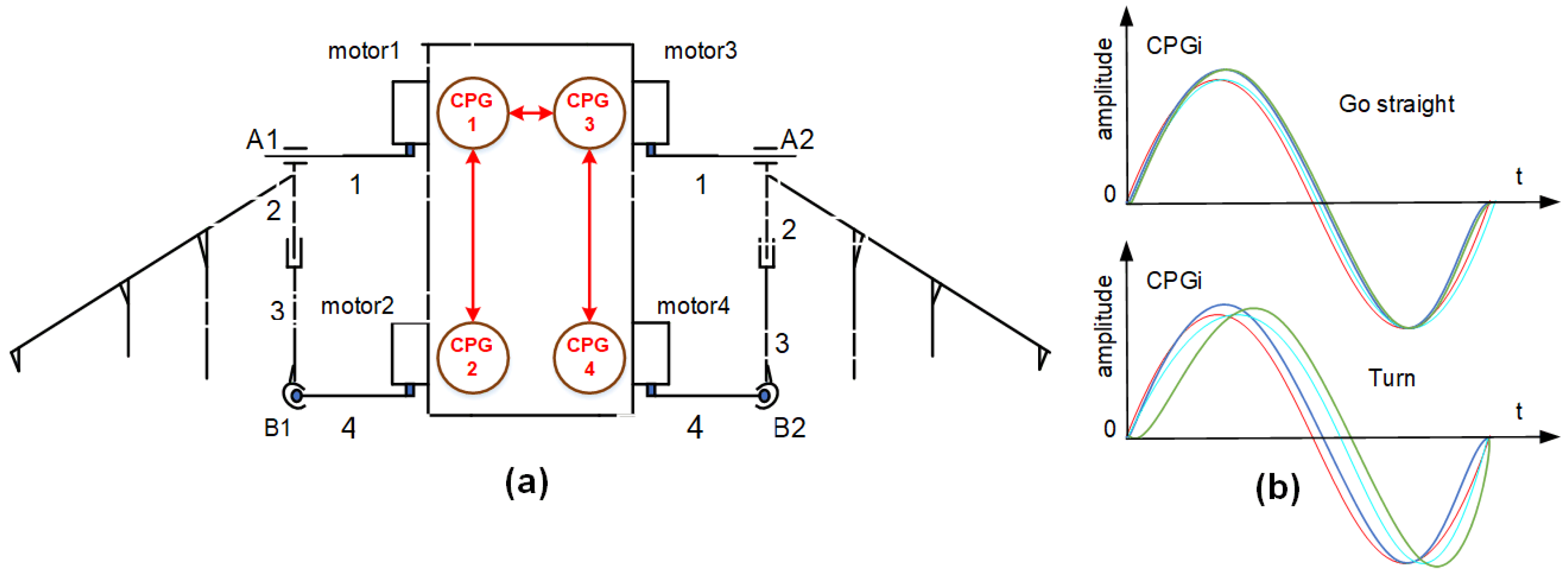
2.4. The Flapping Propulsion System Design

The gliding propulsion has the advantages of high efficiency, energy-saving, and environmental friendliness. However, the maneuverability and stability of the gliding propulsion are not good. When the robot needs high maneuverability and stability, the flapping propulsion method makes up for it. In this section, we design the pectoral fin structure and analyze the flapping propulsion method.
The mechanism schematic is described in Figure 5a, and the three-dimensional model of the pectoral fin is shown in Figure 2d. The flexible pectoral fin comprises driving steering gears 1 and 2, a secondary link mechanism, flexible carbon fiber fin rays, and an elastic skin [36]. When the pectoral fin flaps, the motors drive the steering gear to make the driving rod swing back and forth along the spanwise direction. The central pattern generators (CPGs) generate the motors’ motion law. Controlled by the CPGs, the flexible flapping wing has chord-wise wave transmission and spanwise swing, which imitate the movement of the real manta ray. Symmetrical pectoral fin flapping enables the robotic fish to generate chord-wise power. When the pectoral fins flap asymmetrically, causing a yaw force, this allows the robotic fish to complete heading control (Figure 5b).
The pectoral fins are driven by CPGs, which are implemented as a network of coupled nonlinear oscillators [37,38]. Figure 5a shows the topology of the CPG network and the behavior of the output of each oscillator during flapping propulsion. There is a single oscillator for each motor. The first oscillator (CPG 1) is the one that drives motor 1, oscillators 2–4 drive motors 2–4 (Figure 5a). Each oscillator is implemented as a phase oscillator denoted by three equations as
a ¨ i = k i [ k i 4 ( A i a i ) a ˙ i ]
ϕ ˙ i = 2 π f i + j k i j sin ( ϕ j ϕ i Δ ϕ i j )
ϑ i = a i cos ϕ i + b i
where ϕ i and a i are the state variables representing the phase and the amplitude of oscillator i, respectively; f i and Ai determine its intrinsic frequency and amplitude and k i is a positive constant. Couplings between oscillators are defined by the weights kij and phase biases Δ ϕ i j . ϑ i represents the output of the oscillator after the application of an offset b i , which is used to steer the robot. Each output ϑ i is sent as a set point to the controllers for each motor.

3. Experiments and Results

To verify the gliding and flapping propulsion performance of the biomimetic manta ray robot, we conducted the gliding and flapping propulsion experiments in a natural environment. The performance of the buoyancy system and the mass-adjustment system were verified during the gliding experiments. Similarly, the fixed-depth flapping experiment demonstrated the high maneuverability of the flapping propulsion system. We show the procedure and setup of the experiments in Figure 6. It should be noted that the rectangle mentioned in the text is not a precise rectangle.

3.1. Setup of the Experiments

We show the procedure and setup of the gliding experiment in Figure 6a. The gliding target depth was 30 m, the reference heading was 260°, the buoyancy for descending and ascending was ±550 mL, and the position of the mass block was −40 mm and 30 mm, corresponding to gliding up and down. There were five steps in the gliding experiment: (a) deploying the prototype in the experiment area through a crane from the test ship. The assignment parameters were set in the upper computer control system and the data was sent to the prototype. After the prototype received the mission parameters, it started to analyze the mission requirements and began to execute the gliding mission. (b) The prototype reduced buoyancy and adjusted its attitude through the mass-adjustment system while gliding down. (c) After the target depth of 30 m was reached, the buoyancy began to increase, the mass block moved backward, and the pitch angle changed from negative to positive. (d) The prototype glided up according to the set direction and adjusted the heading angle through the roller mechanism. (e) At the end of the experiment, the prototype transmitted the position coordinates back to the mother ship through the satellite, then the boat found the prototype and recovered it.
The procedure and setup of the flapping experiment are shown in Figure 6b. The reference heading was 85°, and the target depth was 3 m. After the robot arrived at the target depth, it swam a rectangle. The buoyancy and the mass-adjustment system coordinated to keep the prototype near a depth of three meters simultaneously. During the flapping propulsion procedure, the prototype swam using the pectoral fins along the set course, and the reference course was adjusted four times clockwise, each time 90°. Finally, the prototype returned to the original reference course to complete the flapping propulsion experiment.

3.2. The Experiment Results

We carried out the 30 m gliding experiment and swimming rectangle experiment in the lake with the bionic manta ray robot. It demonstrated that the prototype had the performance of gliding and flapping propulsion simultaneously. We show the data analysis of the experiment results in Figure 7, Figure 8, Figure 9, Figure 10 and Figure 11, where Figure 7, Figure 8 and Figure 9 and Figure 10 and Figure 11 were the gliding and the flapping propulsion results, respectively.

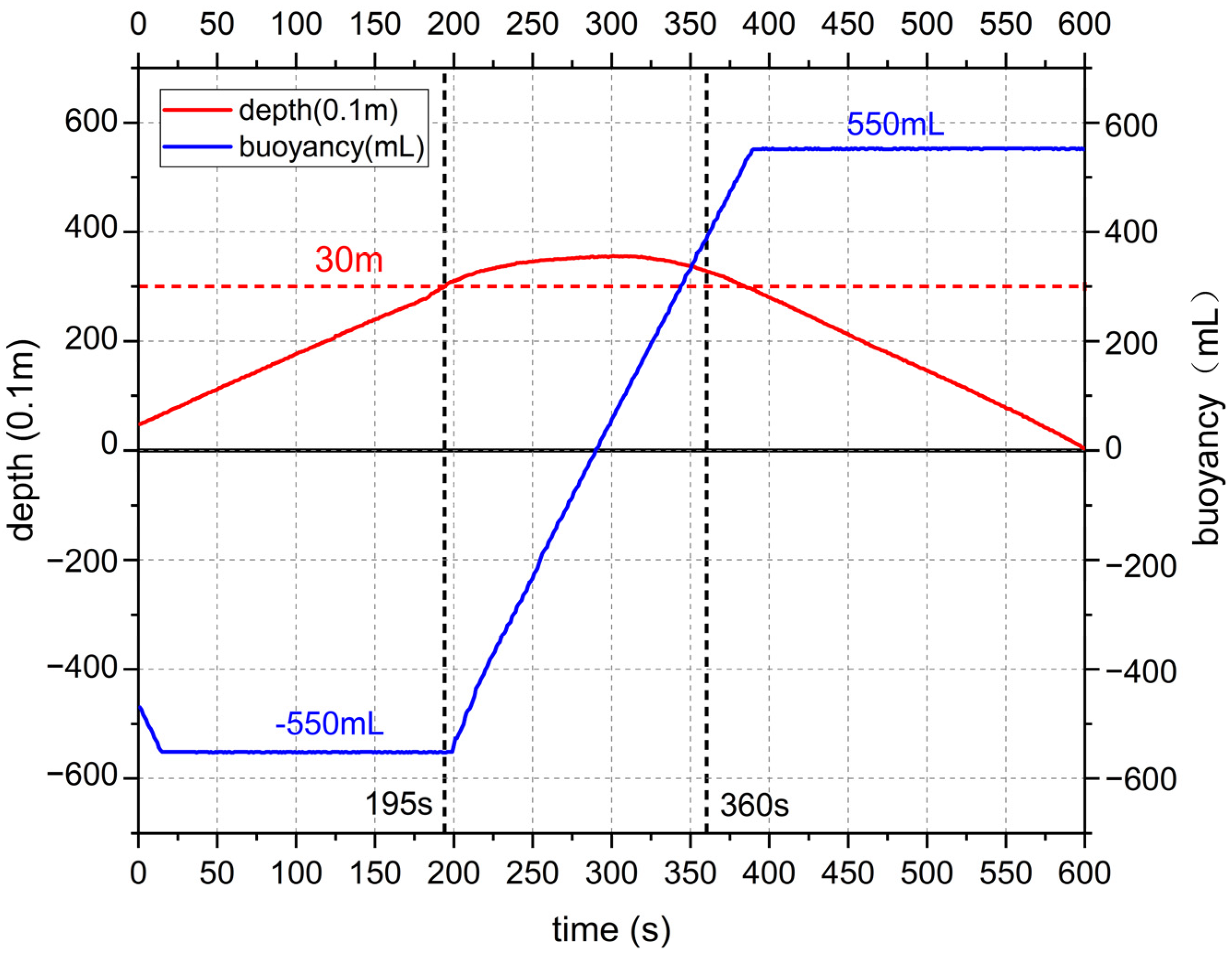
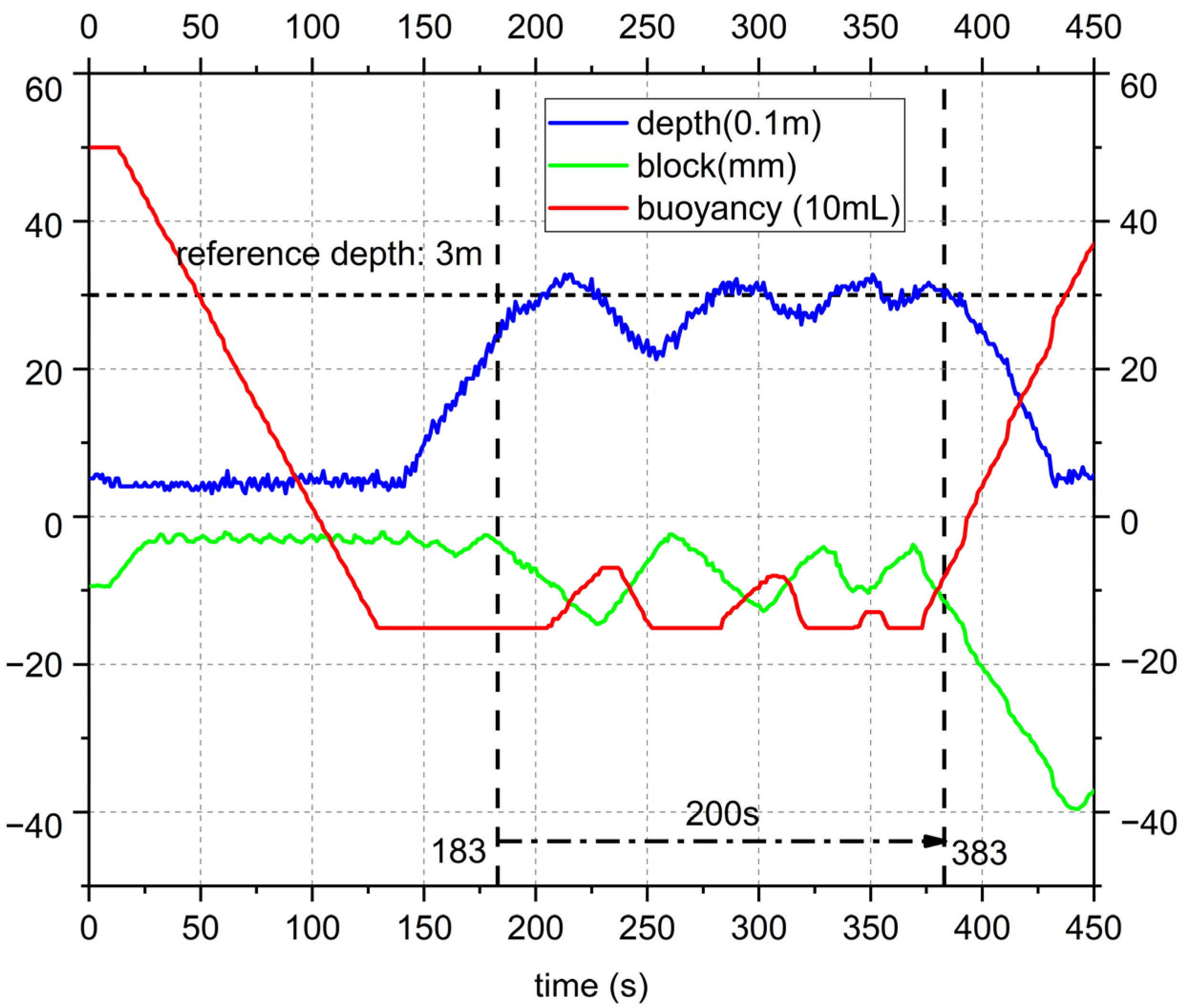
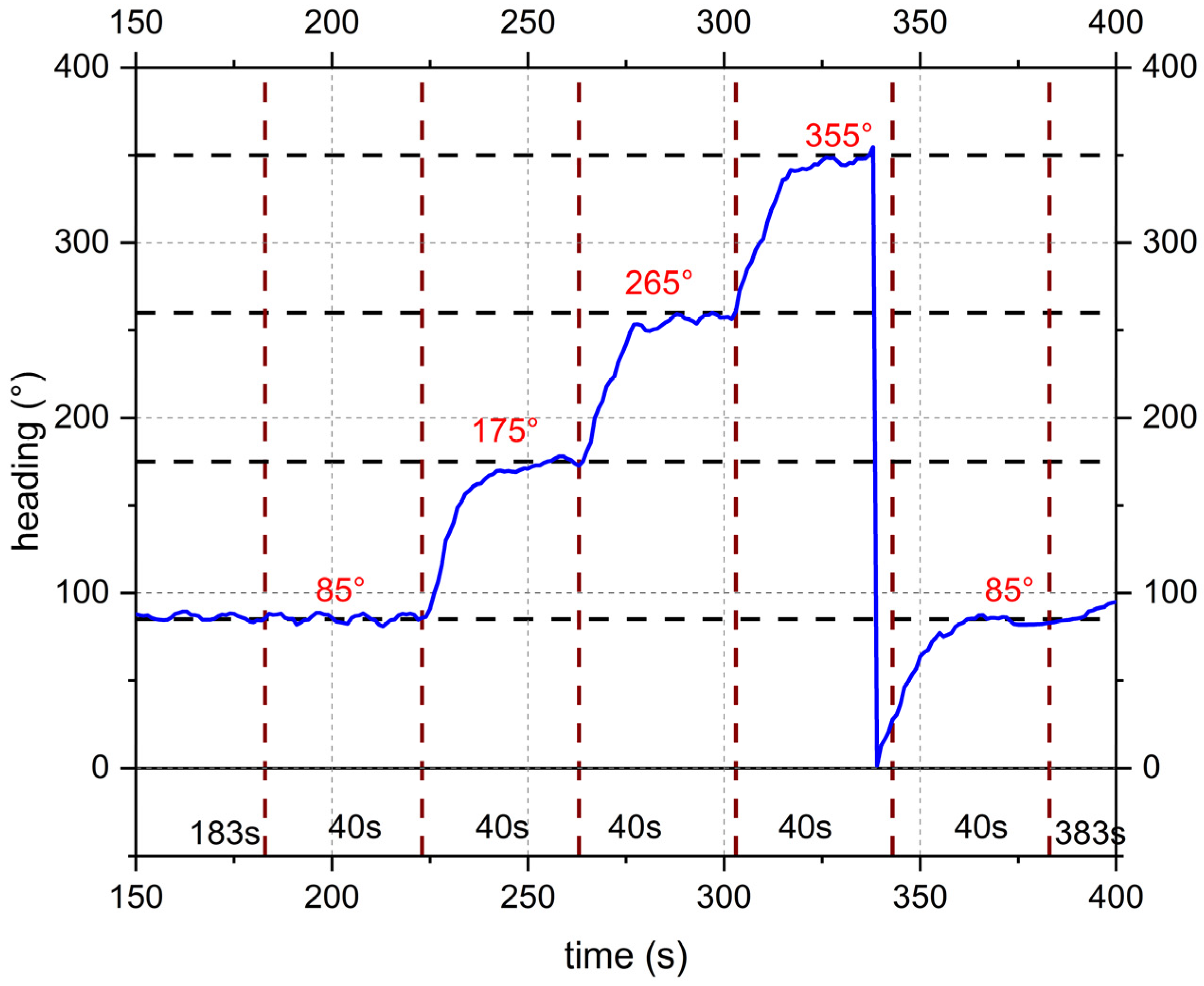
3.2.1. The Gliding Experiment Results

In Figure 7, the buoyancy-adjustment system changed buoyancy to negative 550 mL, and the robot glided down to the target depth of 30 m from 0 s to 195 s. Then it adjusted the buoyancy from negative to 550 mL, which drove the robot to glide to the surface from 195 s to 600 s. This progress verified the performance of the buoyancy-adjustment system. In Figure 8, the reference heading was 260°, the robot heading was 300° at the beginning, and it gradually approached the 260°. We could see in Figure 7 that the prototype was gliding upward from 400 s to 450 s, and the heading angle was about 250°, the mass block’s angle was negative, and the robot roll angle was positive, so the heading gradually tended to 260°. The course changed quickly from 195 s to 360 s because the prototype was in the transition process (Figure 7). In Figure 9, the mass block moved to −30 mm and 40 mm, and the pitch angle was changed when the robot ascended and descended. Thus, the capability of the mass-adjustment system was verified.

3.2.2. The Flapping Propulsion Experiment Results

In Figure 10, the blue, green, and red lines denote the depth, the mass block location, and the buoyancy change with time while the robot swam the rectangle. The blue line shows that it swam from the surface to the target depth, swam the rectangle at the depth of 3 m between 183 s and 283 s, and then the robot swam to the surface. The green and red lines demonstrate the mass block, and buoyancy adjustment to keep the depth.
We show that the heading changed with time when the robot swam the rectangle, in Figure 11. The reference heading changed four times every other 40 s. The heading was adjusted 90° clockwise at 223 s, 263 s, 303 s, and 343 s, respectively. The results proved that the flapping propulsion system performed well.

4. Discussion

Most of the prototypes collected in the literature are proof-of-principle prototypes, and there are few specific practical engineering applications. The prototype in this paper has a load of as much as 20 kg, and it also can take on a mission in a harsh underwater environment. Compared with the prototype we designed, Festo’s BOSS Manta Ray robot [25] has pump propulsion in addition to pectoral fin propulsion, which is faster. Still, its deep-sea pressure bearing capacity and load capacity are smaller. The prototype developed in our present work could withstand a pressure of 10 Mpa. Compared with the underwater gliders, such as the manta ray-like glider [29], it has an advantage in sliding, but the prototype in this article has a shape design mimicking the real manta ray creature and has good hydrodynamic swimming performance.
There are also some limitations of the bionic manta ray robot compared with the existing prototypes.
(1)
The accuracy of the heading control based on the centroid mechanism is not high, which affects the gliding speed.
(2)
The material of the flexible flapping wing is a skeleton plus fiber skin, leading to considerably more resistance compared with real fish during flutter propulsion.
(3)
The flapping propulsion model can achieve a highly maneuverable movement. The motor’s power is limited.
(4)
We located the buoyancy-adjustment system in the head of the prototype; the buoyancy changed with the alteration of the location of the centroid, which would affect the stability of the control system.
We applied the fuzzy controller combined with CPG to adjust the robot’s attitude. However, the parameters must be optimized to improve the control quality in future work. The structure also should be optimized to improve the dynamic stability of the robot. Further, the motor driving mode and the pectoral materials could be changed to alter the hydrodynamic performance and increase propulsion efficiency.

5. Conclusions

We presented a novel integrated gliding and flapping propulsion biomimetic manta ray robot. We designed the manta ray-like shape, the overall structure, the gliding propulsion system including a buoyancy-adjustment system and a mass-adjustment system, and the flapping propulsion system of the prototype; we also analyzed the principles of gliding and flapping locomotion. To verify the performance of the robot, we carried out the gliding and flapping propulsion experiments in a natural environment. The results of the gliding and flapping experiments demonstrated the excellent performance of the designed biomimetic manta ray robot.

Author Contributions

Supervision, Y.C. (Yong Cao), Y.C. (Yonghui Cao), G.P. and Q.H.; writing—original draft, D.Z.; writing—review and editing, D.Z. and Y.C. (Yong Cao). All authors have read and agreed to the published version of the manuscript.

Funding

This research was funded by the National Natural Science Foundation of China (Grant No. 52001260, 51879220); the National Key Research and Development Program of China (Grant No. 2020YFB1313200); the Fundamental Research Funds for the Central Universities (D500210943, D5000210956, D5000210944).

Institutional Review Board Statement

Not applicable.

Informed Consent Statement

Not applicable.

Data Availability Statement

Not applicable.

Acknowledgments

The authors would like to thank all students and engineers for their assistance during the prototype construction and lake experiments in the School of Marine Science and Technology of Northwestern Polytechnical University.

Conflicts of Interest

The authors declare no conflict of interest.

References

  1. Domenici, P.; Blake, R.W. Review the Kinematics and Performance of Fish Fast-Start Swimming. J. Exp. Biol. 1997, 200, 1165–1178. [Google Scholar] [CrossRef] [PubMed]
  2. Colgate, J.E.; Lynch, K.M. Mechanics and Control of Swimming: A Review. IEEE J. Ocean. Eng. 2004, 29, 660–673. [Google Scholar] [CrossRef]
  3. Roper, D.T.; Sharma, S.; Sutton, R.; Culverhouse, P. A Review of Developments towards Biologically Inspired Propulsion Systems for Autonomous Underwater Vehicles. Proc. Inst. Mech. Eng. Part M J. Eng. Marit. Environ. 2011, 225, 77–96. [Google Scholar] [CrossRef]
  4. Wu, T.Y. Fish Swimming and Bird/Insect Flight. Annu. Rev. Fluid Mech. 2011, 43, 25–58. [Google Scholar] [CrossRef]
  5. Gray, J. Studies in Animal Locomotion, VI. The Propulsive Powers of the Dolphin. J. Exp. Biol. 1936, 13, 192–199. [Google Scholar] [CrossRef]
  6. Triantafyllou, M.S.; Triantafyllou, G.S. An Efficient Swimming Machine. Sci. Am. 1995, 272, 64–70. [Google Scholar] [CrossRef]
  7. Stix, G. RoboTuna. Sci. Am. 1994, 270, 142. [Google Scholar] [CrossRef]
  8. Rus, D.; Tolley, M.T. Design, Fabrication and Control of Soft Robots. Nature 2015, 521, 467–475. [Google Scholar] [CrossRef] [Green Version]
  9. Wang, R.; Wang, S.; Wang, Y.; Cheng, L.; Tan, M. Development and Motion Control of Biomimetic Underwater Robots: A Survey. IEEE Trans. Syst. Man Cybern. Syst. 2022, 52, 833–844. [Google Scholar] [CrossRef]
  10. Ahmed, F.; Waqas, M.; Javed, B.; Soomro, A.M.; Kumar, S.; Ashraf, H.; Khan, U.; Kim, K.H.; Choi, K.H. Decade of Bio-Inspired Soft Robots: A Review. Smart Mater. Struct. 2022, 31, 7. [Google Scholar] [CrossRef]
  11. Ahmed, F.; Waqas, M.; Shaikh, B.; Khan, U.; Soomro, A.M.; Kumar, S.; Ashraf, H.; Memon, F.H.; Choi, K.H. Multi-Material Bio-Inspired Soft Octopus Robot for Underwater Synchronous Swimming. J. Bionic Eng. 2022, 1–13. [Google Scholar] [CrossRef]
  12. Soomro, A.M.; Memon, F.H.; Lee, J.-W.; Ahmed, F.; Kim, K.H.; Kim, Y.S.; Choi, K.H. Fully 3D Printed Multi-Material Soft Bio-Inspired Frog for Underwater Synchronous Swimming. Int. J. Mech. Sci. 2021, 210, 106725. [Google Scholar] [CrossRef]
  13. Ahmed, F.; Muhammad, W.; Javed, B.; Soomro, A.M.; Kumar, S.; Hina, A.; Khan, U.; Kim, K.H.; Choi, K.H. Decade of Bio-Inspired Soft Robots: A Review. Smart Mater. Struct. 2022, 31, 073002. [Google Scholar] [CrossRef]
  14. Sfakiotakis, M.; Lane, D.M.; Davies, J. Review of Fish Swimming Modes for Aquatic Locomotion. IEEE J Ocean. Eng. 1999, 24, 237–252. [Google Scholar] [CrossRef] [Green Version]
  15. Xie, F.; Zuo, Q.; Chen, Q.; Fang, H.; He, K.; Du, R.; Zhong, Y.; Li, Z. Designs of the Biomimetic Robotic Fishes Performing Body and/or Caudal Fin (BCF) Swimming Locomotion: A Review. J. Intell. Robot. Syst. 2021, 102, 13. [Google Scholar] [CrossRef]
  16. Scaradozzi, D.; Palmieri, G.; Costa, D.; Pinelli, A. BCF Swimming Locomotion for Autonomous Underwater Robots: A Review and a Novel Solution to Improve Control and Efficiency. Ocean Eng. 2017, 130, 437–453. [Google Scholar] [CrossRef]
  17. Yu, J.; Wu, Z.; Su, Z.; Wang, T.; Qi, S. Motion Control Strategies for a Repetitive Leaping Robotic Dolphin. IEEE/ASME Trans. Mechatron. 2019, 24, 913–923. [Google Scholar] [CrossRef]
  18. Manta Ray FAQ. Available online: http://www.elasmo-research.org/education/topics/lh_manta_faq.htm (accessed on 23 March 2022).
  19. Xu, Y.; Zong, G.; Bi, S.; Gao, J. Initial Development of a Flapping Propelled Unmanned Underwater Vehicle (UUV). In Proceedings of the 2007 IEEE International Conference on Robotics and Biomimetics (ROBIO), Sanya, China, 15–18 December 2007; pp. 524–529. [Google Scholar]
  20. Cai, Y.; Bi, S.; Zhang, L.; Gao, J. Design of a Robotic Fish Propelled by Oscillating Flexible Pectoral Foils. In Proceedings of the 2009 IEEE/RSJ International Conference on Intelligent Robots and Systems, St. Louis, MO, USA, 10–15 October 2009; pp. 2138–2142. [Google Scholar]
  21. Gao, J.; Bi, S.; Li, J.; Liu, C. Design and Experiments of Robot Fish Propelled by Pectoral Fins. In Proceedings of the 2009 IEEE International Conference on Robotics and Biomimetics (ROBIO), Guilin, China, 19–23 December 2009; p. 6. [Google Scholar]
  22. Cai, Y.; Bi, S.; Zhang, L. Design and Implication of a Bionic Pectoral Fin Imitating Cow-Nosed Ray. In Proceedings of the 2010 IEEE/RSJ International Conference on Intelligent Robots and Systems, Taipei, Taiwan, 18–22 October 2010; p. 5. [Google Scholar]
  23. Zheng, L.; Bi, S.; Cai, Y.; Niu, C. Design and Optimization of a Robotic Fish Mimicking Cow-Nosed Ray. In Proceedings of the 2010 IEEE International Conference on Robotics and Biomimetics, Tianjin, China, 14–18 December 2010; pp. 1075–1080. [Google Scholar]
  24. Ma, H.; Cai, Y.; Wang, Y.; Bi, S.; Gong, Z. A Biomimetic Cownose Ray Robot Fish with Oscillating and Chordwise Twisting Flexible Pectoral Fins. Ind. Robot Int. J. 2015, 42, 214–221. [Google Scholar] [CrossRef]
  25. BOSS Project|EvoLogics. Available online: https://evologics.de/projects/boss (accessed on 23 March 2022).
  26. Glushko, I.; Olenew, E.; Komar, M.; Kniese, L.; Sokolovskyi, R.; Kebkal, O.; Bannasch, R.; Kebkal, K. Software Control Architecture for the BOSS Manta Ray AUV Actuation System. In Proceedings of the 2018 IEEE/OES Autonomous Underwater Vehicle Workshop (AUV), Porto, Portugal, 6–9 November 2018; pp. 1–5. [Google Scholar]
  27. Teubler, T.; Hellbruck, H. Design of Expert Systems for Autonomous Underwater Vehicle Control. In Proceedings of the OCEANS 2016 MTS/IEEE Monterey, Monterey, CA, USA, 19–23 September 2016; pp. 1–6. [Google Scholar]
  28. Wang, Z.; Wang, Y.; Li, J.; Hang, G. A Micro Biomimetic Manta Ray Robot Fish Actuated by SMA. In Proceedings of the 2009 IEEE International Conference on Robotics and Biomimetics (ROBIO), Guilin, China, 19–23 December 2009; pp. 1809–1813. [Google Scholar]
  29. Zhu, Y.; Liu, Y.; Zhang, L.; Wang, Y.; Niu, W.; Huang, C. Dynamic Model and Motion Characteristics of an Underwater Glider with Manta-Inspired Wings. J. Bionic Eng. 2022, 19, 1–15. [Google Scholar] [CrossRef]
  30. Zhou, C.; Low, K.-H. Better Endurance and Load Capacity: An Improved Design of Manta Ray Robot (RoMan-II). J. Bionic Eng. 2010, 7, S137–S144. [Google Scholar] [CrossRef]
  31. Zhou, C.; Low, K.H. Design and Locomotion Control of a Biomimetic Underwater Vehicle With Fin Propulsion. IEEE/ASME Trans. Mechatron. 2012, 17, 25–35. [Google Scholar] [CrossRef]
  32. Cao, Y.; Lu, Y.; Cai, Y.; Bi, S.; Pan, G. CPG-Fuzzy-Based Control of a Cownose-Ray-like Fish Robot. Ind. Robot Int. J. Robot. Res. Appl. 2019, 46, 779–791. [Google Scholar] [CrossRef]
  33. Bal, C.; Ozmen Koca, G.; Korkmaz, D.; Akpolat, Z.H.; Ay, M. CPG-Based Autonomous Swimming Control for Multi-Tasks of a Biomimetic Robotic Fish. Ocean Eng. 2019, 189, 106334. [Google Scholar] [CrossRef]
  34. Sherman, J.; Davis, R.E.; Owens, W.B.; Valdes, J. The Autonomous Underwater Glider “Spray”. IEEE J. Ocean. Eng. 2001, 26, 437–446. [Google Scholar] [CrossRef] [Green Version]
  35. Hao, Y.; Cao, Y.; Cao, Y.; Huang, Q.; Pan, G. Course Control of a Manta Robot Based on Amplitude and Phase Differences. J. Mar. Sci. Eng. 2022, 10, 285. [Google Scholar] [CrossRef]
  36. Xing, C.; Cao, Y.; Cao, Y.; Pan, G.; Huang, Q. Asymmetrical Oscillating Morphology Hydrodynamic Performance of a Novel Bionic Pectoral Fin. J. Mar. Sci. Eng. 2022, 10, 289. [Google Scholar] [CrossRef]
  37. Ijspeert, A.J. Central Pattern Generators for Locomotion Control in Animals and Robots: A Review. Neural Netw. 2008, 21, 642–653. [Google Scholar] [CrossRef]
  38. Crespi, A.; Ijspeert, A.J. Online Optimization of Swimming and Crawling in an Amphibious Snake Robot. IEEE Trans. Robot. 2008, 24, 75–87. [Google Scholar] [CrossRef] [Green Version]
Figure 1. The shape design of the manta ray robot. (a) The schematic diagram of a real manta ray; (b) the scale of the robot; (c) the NACA0022 and optimized airfoils; (d) the NACA0016 and optimized airfoils; (e) the NACA0008 and optimized airfoils.
Jmse 10 00924 g001
Figure 2. The structural model and prototype of the manta robot. (a) The three-dimensional overall structural model of the manta robot; (b) the manta ray robot prototype on display; (c) the buoyancy-adjustment system three-dimensional model; (d) the flexible pectoral fin model; (e) the mass-adjustment system’s three-dimensional model.
Jmse 10 00924 g002
Figure 3. Earth-fixed (inertial) reference and body-fixed reference frames.
Jmse 10 00924 g003
Figure 4. The force analysis diagram of the robot gliding up and down. In the charts, the red dots indicate the locations of the centroid, the black dots represent the locations of the center of buoyancy, and the white dots denote the possible locations of the centroid. The red dotted lines indicate that if the centroids move from the red dots to the green ones, the red curve moments will form. (a) Force analysis diagram of the robot when it is stationary. (b) Force analysis diagram of the robot when it is gliding down. (c) Force analysis diagram of the robot when it is gliding up.
Jmse 10 00924 g004
Figure 5. Analysis of the flapping propulsion method. The motors 1, 2, 3, and 4 are controlled by CPG 1, 2, 3, and 4, respectively. (a) Schematic diagram of the pectoral fins and CPG network topology; (b) the four CPG outputs when the robot goes straight and turns. When the robot goes straight, the CPG 1 and CPG 3 output the same signals, and the CPG 2 and the CPG 4 output the same lines. When the robot turns, the CPGs will output different drive signals. The red, bule, green, and brown lines denote the CPG1, CPG2, CPG3, and CPG4, respectively.
Jmse 10 00924 g005
Figure 6. The gliding and flapping experiments’ setup and the experiment procedure display. (a) The gliding experiment’s procedure and setup; (b) the flapping experiment’s procedure and setup; (c) the prototype’s examination before deployment; (d) the gliding experiment carried out in the lake, and the prototype starting to glide down.
Jmse 10 00924 g006
Figure 7. The depth and buoyancy changed with time. The red dot line denotes the target depth of 30 m. The picture shows the prototype glide to the target depth of 30 m and then float up to the surface. The buoyancy was set to −550 mL and 550 mL when gliding down and up, respectively.
Jmse 10 00924 g007
Figure 8. The heading, robot roll angle, and mass block roll angle changed with time. The dotted red line denotes the reference heading was 260°.
Jmse 10 00924 g008
Figure 9. The location of the mass block and the robot pitch angle changed with time. We set the mass block to −30 mm when the robot glided down, and the pitch was about −18°. The prototype changed the block location from −30 mm to 40 mm when the robot glided up, and the pitch angle was about 23°.
Jmse 10 00924 g009
Figure 10. The depth, mass block location, and buoyancy changed with time when the robot swam the rectangle.
Jmse 10 00924 g010
Figure 11. The heading changed with time when it swam the rectangle, it swam stably for 40 s for each side of the rectangle, and the reference headings were 85, 175, 265, and 355°, respectively.
Jmse 10 00924 g011
Table 1. Comparison of the underwater robots.
TermSpray [34]BWUG [29]Robotic Manta [35]Robot Dolphin [17]Proposed Robot
Length × Width × height2 m × 1.2 m × 0.3 m2.3 m × 1.3 m0.6 m × 0.8 m × 0.15 m0.72 m × 0.12 m × 0.13 m1.5 m × 3.2 m × 0.5 m
Payload capacityYesYes NoNoYes
Multiple propulsion modesNoYesNoNoYes
Bionic shapeNoNoYesYesYes
Adapts to harsh underwater
environment
Yes YesNoNoYes
Table 2. Six DOF motion components of the manta ray robot.
DOFInertial Position and Euler AnglesBody-Fixed VelocitiesForces and Moments
Motion in the x-direction(surge)x u X
Motion in the y-direction(sway)y v Y
Motion in the z-direction(heave)z w Z
Rotation about the x-axis φ pK
Rotation about the y-axis θ qM
Rotation about the y-axis ψ rn
Publisher’s Note: MDPI stays neutral with regard to jurisdictional claims in published maps and institutional affiliations.

