A Direct Damage Stability Calculation Method for an Onboard Loading Computer
Abstract
:1. Introduction
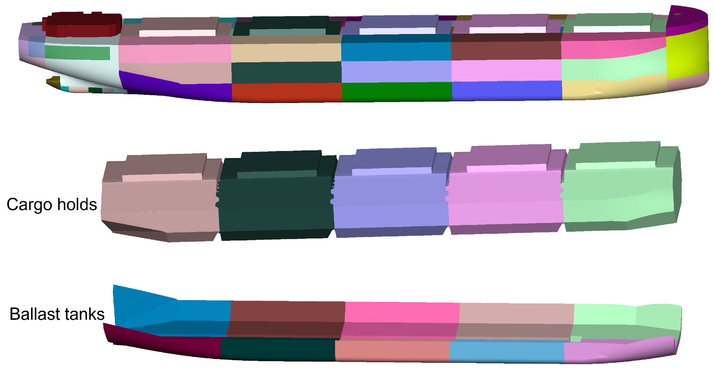
2. Establishment of the 3D Model Database
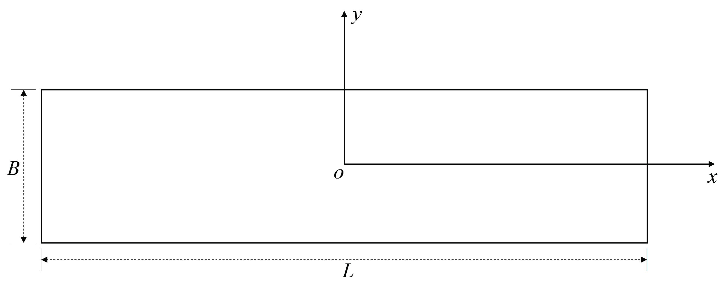
3. Simplified Newton Iteration Method for Damage Stability
3.1. Simplified Newton Iteration Method
3.2. Iteration Termination Condition
4. Results
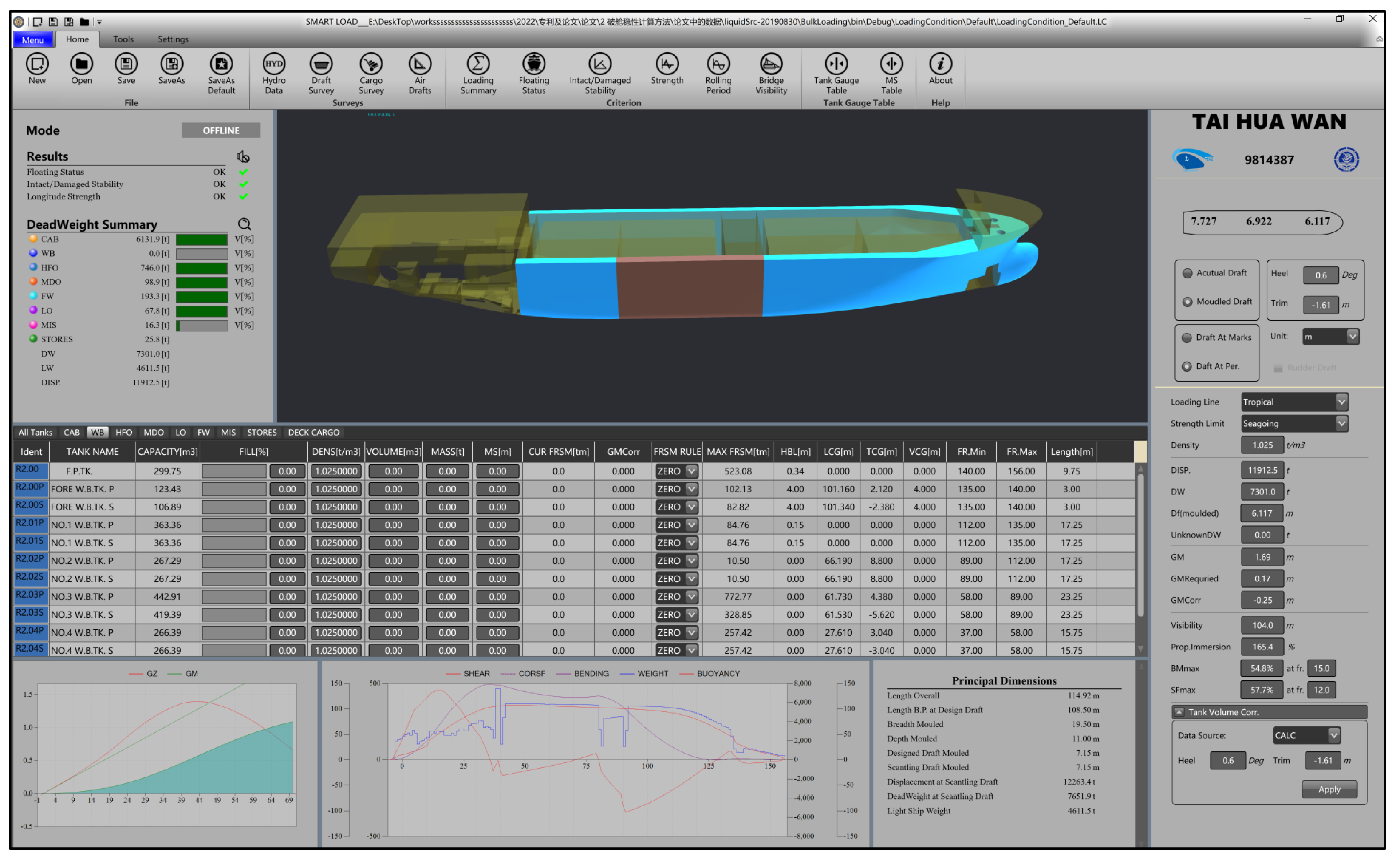
4.1. Initial Conditions
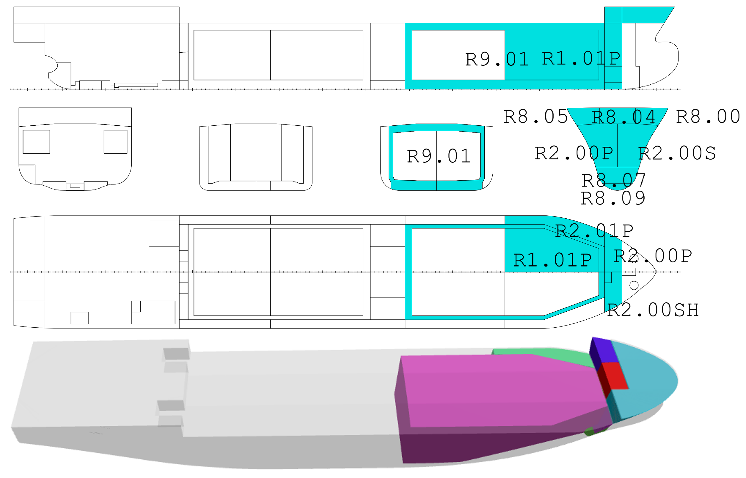
4.2. Damage Cases
4.3. Damage Stability Results
- The feasibility and accuracy of the algorithm are verified. The calculation error is small. The maximum and average error of the 18 loading conditions are 0.013 m and 0.002 m, respectively.
- The real-time performance of the algorithm is verified. The convergence rate of the algorithm is fast. The maximum and average number of iterations of the 18 loading conditions are 53 and 9, respectively.
5. Conclusions
Author Contributions
Funding
Data Availability Statement
Acknowledgments
Conflicts of Interest
References
- IACS. Computer Software for Onboard Stability Calculations, UICS Unified Requirement L5 Rev4 CLN; IACS: London, UK, 2020. [Google Scholar]
- Ruponen, P.; Pennanen, P.; Manderbacka, T. On the alternative approaches to stability analysis in decision support for damaged passenger ships. WMU J. Marit. Aff. 2019, 18, 477–494. [Google Scholar] [CrossRef] [Green Version]
- IACS. Requirements for Loading Conditions, Loading Manuals and Loading Instruments, UICS Unified Requirement S1 Rev7; IACS: London, UK, 2010. [Google Scholar]
- Abbas, U.; Khalid, S.; Riaz, Z.; Zubair, A.; Khalid, H. Development of a Large Angle Stability Tool For The Ships and Boats. In Proceedings of the 2021 International Bhurban Conference on Applied Sciences and Technologies (IBCAST), Islamabad, Pakistan, 12–16 January 2021; pp. 873–880. [Google Scholar]
- Pan, D.W.; Lin, C.X.; Liu, Z.J.; Sun, D.P. Calculation on the uprighting process of a capsized Ship. Brodogr. Teor. Praksa Brodogr. Pomor. Teh. 2016, 67, 115–132. [Google Scholar] [CrossRef] [Green Version]
- Lee, D.; Lee, S.S.; Park, B.J.; Kim, S.Y. A study on the framework for survivability assessment system of damaged ships. Ocean Eng. 2005, 32, 1122–1132. [Google Scholar] [CrossRef]
- Ólçer, A.; Majumder, J. A case-based decision support system for flooding crises onboard ships. Qual. Reliab. Eng. Int. 2006, 22, 59–78. [Google Scholar] [CrossRef]
- Jasionowski, A. Decision support for ship flooding crisis management. Ocean Eng. 2011, 38, 1568–1581. [Google Scholar] [CrossRef]
- Martins, P.T.; Lobo, V. Real-Time decision support system for managing ship stability under damage. In Proceedings of the OCEANS 2011 IEEE-Spain, Santander, Spain, 6–9 June 2011; pp. 1–7. [Google Scholar]
- Hu, L.F.; Ma, K.; Ji, Z.S. AM–H method-based decision support system for flooding emergencies onboard warship. Ocean Eng. 2013, 58, 192–200. [Google Scholar] [CrossRef]
- Hu, L.f.; Tian, Z.; Sun, Z.; Zhang, Q.; Feng, B. Genetic algorithm-based counter-flooding decision model for damaged warship. Int. Shipbuild. Prog. 2015, 62, 1–15. [Google Scholar] [CrossRef]
- Varela, J.M.; Rodrigues, J.; Soares, C.G. On-board decision support system for ship flooding emergency response. Procedia Comput. Sci. 2014, 29, 1688–1700. [Google Scholar] [CrossRef] [Green Version]
- Calabrese, F.; Mancarella, L.; Zizzari, A.A.; Corallo, A. A FEA-like method for evaluating the ship equilibrium point. IFAC Proc. Vol. 2012, 45, 115–120. [Google Scholar] [CrossRef]
- Calabrese, F.; Cataldo, M.; De Pascalis, A.; Mancarella, L.; Ostuni, L.; Zizzari, A.A. A method for evaluating the ship equilibrium point using 3D meshes developed for embedded device. In Proceedings of the OCEANS 2015-Genova, Genova, Italy, 18–21 May 2015; pp. 1–6. [Google Scholar]
- Schalck, S.; Baatrup, J. Hydrostatic stability calculations by pressure integration. Ocean Eng. 1990, 17, 155–169. [Google Scholar] [CrossRef]
- Zhang, X.; Lin, Z.; Mancini, S.; Li, P.; Li, Z.; Liu, F. A numerical investigation on the flooding process of multiple compartments based on the volume of fluid method. J. Mar. Sci. Eng. 2019, 7, 211. [Google Scholar] [CrossRef] [Green Version]
- Sun, X.; Ni, Y.; Liu, C.; Wang, Z.; Yin, Y. A practical method for stability assessment of a damaged ship. Ocean Eng. 2021, 222, 108594. [Google Scholar] [CrossRef]
- Ruth, E.; Rognebakke, O. CFD in damage stability. In Proceedings of the 17th International Ship Stability Workshop, Helsinki, Finland, 10–12 June 2019; pp. 10–12. [Google Scholar]
- Lu, C.; Lin, Y.; Ji, Z. Free trim calculation using genetic algorithm based on NURBS shipform. Int. Shipbuild. Prog. 2007, 54, 45–62. [Google Scholar]
- Ding, N.; Yu, J.X. Nonlinear optimization method of ship floating condition calculation in wave based on vector. China Ocean Eng. 2014, 28, 471–478. [Google Scholar] [CrossRef]
- Gao, Q.; Vassalos, D. Numerical study of damage ship hydrodynamics. Ocean Eng. 2012, 55, 199–205. [Google Scholar] [CrossRef]
- Ruponen, P.; Queutey, P.; Kraskowski, M.; Jalonen, R.; Guilmineau, E. On the calculation of cross-flooding time. Ocean Eng. 2012, 40, 27–39. [Google Scholar] [CrossRef]
- Ruponen, P.; Manderbacka, T.; Lindroth, D. On the calculation of the righting lever curve for a damaged ship. Ocean Eng. 2018, 149, 313–324. [Google Scholar] [CrossRef]
- Lloyd’s Register of Shipping. Loading Computer Software—General Approval—Post URL5. Available online: https://www.lr.org/en/lr-approvals/ (accessed on 16 July 2022).
- Onboard-NAPA Ltd. Onboard-NAPA. Available online: https://directory.marinelink.com/companies/company/onboardnapa-ltd-203577 (accessed on 16 July 2022).
- Delta Marine Engineering & Computer Trading Co. Deltaload. Available online: http://www.deltamarine.com.tr/en/services/ship-loading-software.php (accessed on 16 July 2022).
- Hanla IMS CO., Ltd. Loadplus. Available online: http://www.hanlaims.com/ (accessed on 16 July 2022).
- Herbert-Abs Software Solutions. CargoMax. Available online: https://www.herbert-abs.com/cargomax-for-bulk-carriers (accessed on 16 July 2022).
- Kockum Sonics, A.B. Loadmaster. Available online: http://www.kockumsonics.com/products/marine/loadmaster.htm (accessed on 16 July 2022).
- Kongsberg Maritime, A.S. K-LOAD. Available online: https://www.kongsberg.com/maritime/products/tank-gauging-and-measurment-systems/loading-and-stability-systems/k-load/ (accessed on 16 July 2022).
- Seasafe Marine Software (UK) Ltd. LR SEASAFE Onboard (Gstab). Available online: https://www.lr.org.cn/lr-seasafe-loading-and-stability/lr-seasafe-onboard/ (accessed on 16 July 2022).
- Techmarine S/W, Co. Ltd. SHIPMANAGER-88. Available online: http://www.techmarine.net/main.htm (accessed on 16 July 2022).
- Shen, H.; Liu, C.; Yin, Y.; Sun, X. Automatic Stowage of Bulk Carrier Based on Ship Floating-State Control. J. Ship Res. 2019, 64, 298–312. [Google Scholar] [CrossRef]
- Liu, W.B.; Ming, F.R.; Wang, S.P.; Zhang, S. Application of smoothed particle hydrodynamics method for simulating the flooding process of a damaged ship cabin in full-time domain. Ocean Eng. 2022, 248, 110716. [Google Scholar] [CrossRef]


| Type | Description |
|---|---|
| Type 1 | Software calculating intact stability only (for vessels not required to meet a damage stability criterion). |
| Type 2 | Software calculating intact stability and checking damage stability on the basis of a limit curve (e.g., for vessels applicable to SOLAS Part B-1 damage stability calculations, etc.) or checking all the stability requirements (intact and damage stability) on the basis of a limit curve. |
| Type 3 | Software calculating intact stability and damage stability by the direct application of preprogrammed damage cases based on the relevant conventions or codes for each loading condition (for some tankers, etc.). |
| Type 4 | Software calculating intact stability and damage stability by the direct application of preprogrammed damage cases based on the relevant conventions or codes for each loading condition (for some tankers etc.). |
| Method | Advantages | Disadvantages |
|---|---|---|
| Newton Iteration Method | Fast convergence speed (3–5 iterations). | When calculating the Jacobian matrix coefficient, it is difficult to calculate the inclined waterline parameters. In some cases, the program will fail to converge. |
| CFD | Damage stability calculation in the time domain. | The calculation time is long. |
| Optimization method | Compared with the Newton Iteration Method, there is no need to calculate the inclined waterline coefficient. Only the displacement and floating center of the ship need to be calculated. It has good robustness. | More iterations are required. |
| Commercial software | Algorithms are stable and reliable with good real-time performance, and have been applied in practice. | The details of the calculation methods are not public. |
| Item | Value | Unit |
|---|---|---|
| Ship name | TAI HUA WAN | |
| Type of ship | ASPHALT TANKER | |
| IMO number | 9,814,387 | |
| Overall length | 114.92 | m |
| Length B.P | 108.5 | m |
| Breadth | 19.5 | m |
| Depth | 11 | m |
| Scantling draft | 6.98 | m |
| Displacement at full load summer draft (even keel) | 11,914.2 | t |
| Deadweight at full load summer draft (even keel) | 7414.2 | dwt |
| Service speed (at designed draft) | 13.95 | kn |
| Light ship weight | 4611.5 | t |
| IDENT | CONDITION NAME |
|---|---|
| INI01 | FULLY LOADED WITH HOMOGENEOUS CARGO (S.G. = 0.8872T/M3), DEPARTURE |
| INI02 | FULLY LOADED WITH HOMOGENEOUS CARGO (S.G. = 0.8872T/M3), ARRIVAL |
| INI03 | FULLY LOADED WITH 0.98T/M3 CARGO, DEPARTURE |
| INI04 | FULLY LOADED WITH 0.98T/M3 CARGO, ARRIVAL |
| INI05 | FULLY LOADED WITH 0.926T/M3 CARGO, DEPARTURE |
| INI06 | FULLY LOADED WITH 0.926T/M3 CARGO, ARRIVAL |
| INI07 | FULLY LOADED WITH 1.04T/M3 CARGO, DEPARTURE |
| INI08 | FULLY LOADED WITH 1.04T/M3 CARGO, ARRIVAL |
| INI09 | NO.14 C/H FULL NO.23 C/H EMPTY 1.04T/M3, DEPARTURE |
| INI10 | NO.14 C/H FULL NO.23 C/H EMPTY 1.04T/M3, ARRIVAL |
| INI11 | NO.23 C/H FULL NO.14 C/H EMPTY 1.04T/M3, DEPARTURE |
| INI12 | NO.23 C/H FULL NO.14 C/H EMPTY 1.04T/M3, ARRIVAL |
| INI13 | NO.13 C/H FULL NO.24 C/H EMPTY 1.04T/M3, DEPARTURE |
| INI14 | NO.13 C/H FULL NO.24 C/H EMPTY 1.04T/M3, ARRIVAL |
| INI15 | NO.24 C/H FULL NO.13 C/H EMPTY 1.04T/M3, DEPARTURE |
| INI16 | NO.24 C/H FULL NO.13 C/H EMPTY 1.04T/M3, ARRIVAL |
| INI17 | PARTIALLY LOADED WITH HOMOGENEOUS CARGO (S.G. = 1.04T/M3), DEPARTURE |
| INI18 | PARTIALLY LOADED WITH HOMOGENEOUS CARGO (S.G. = 1.04T/M3), ARRIVAL |
| NAME | Draft | Trim | Heel Angle | Displacement | LCB | VCB | GM |
|---|---|---|---|---|---|---|---|
| (m) | (m) | (deg) | (t) | (m) | (m) | (m) | |
| INI01 | 6.92 | −1.62 | 0.612 | 11,912.4 | 52.797 | 3.743 | 1.705 |
| INI02 | 6.559 | −1.131 | 0.375 | 11,135.7 | 53.725 | 3.52 | 1.84 |
| INI03 | 6.92 | −1.624 | 0.577 | 11,912.4 | 52.792 | 3.743 | 1.804 |
| INI04 | 6.559 | −1.134 | 0.354 | 11,135.7 | 53.72 | 3.52 | 1.946 |
| INI05 | 6.92 | −1.623 | 0.608 | 11,913.2 | 52.794 | 3.743 | 1.714 |
| INI06 | 6.559 | −1.133 | 0.373 | 11,136.5 | 53.722 | 3.521 | 1.849 |
| INI07 | 6.92 | −1.624 | 0.55 | 11,913.4 | 52.791 | 3.743 | 1.891 |
| INI08 | 6.559 | −1.135 | 0.338 | 11,136.7 | 53.719 | 3.521 | 2.039 |
| INI09 | 6.359 | −1.659 | 0.689 | 10,769.7 | 53.019 | 3.429 | 1.806 |
| INI10 | 5.991 | −1.121 | 0.463 | 9993 | 54.069 | 3.201 | 1.95 |
| INI11 | 6.303 | −1.072 | 0.675 | 10,613.8 | 53.97 | 3.375 | 1.72 |
| INI12 | 5.926 | −0.461 | 0.414 | 9837.1 | 55.116 | 3.149 | 1.861 |
| INI13 | 5.95 | −1.428 | 0.692 | 9928.9 | 53.602 | 3.189 | 1.713 |
| INI14 | 5.567 | −0.776 | 0.428 | 9152.2 | 54.805 | 2.957 | 1.884 |
| INI15 | 6.517 | −1.07 | 0.696 | 11,046.9 | 53.842 | 3.495 | 1.707 |
| INI16 | 6.146 | −0.505 | 0.447 | 10,270.2 | 54.927 | 3.272 | 1.83 |
| INI17 | 5.833 | −1.401 | 0.566 | 9693.9 | 53.703 | 3.122 | 2.193 |
| INI18 | 5.445 | −0.717 | 0.338 | 8917.2 | 54.949 | 2.889 | 2.421 |
| IDENT | NAME | PERM | VOL | LCG | TCG | VCG |
|---|---|---|---|---|---|---|
| m3 | m | m | m | |||
| R8.05 | PAINT STORE | 0.95 | 45.6 | 101.19 | 5.79 | 12.88 |
| R8.00 | BOSUN STORE | 0.95 | 286.9 | 105.28 | −0.92 | 12.97 |
| R8.04 | WINDLASS CTR. ROOM | 0.95 | 52.5 | 101.25 | 0 | 12.9 |
| R8.07 | E.F.P.RM | 0.95 | 78.2 | 100.99 | −0.2 | 3.77 |
| R8.09 | LOGSOUND | 0.95 | 14.7 | 101.15 | 0 | 0.7 |
| R2.00P | FORE W.B.TK.P | 0.95 | 126 | 101.18 | 2.89 | 8.07 |
| R2.00S | FORE W.B.TK.S | 0.95 | 109.1 | 101.31 | −3.2 | 8.12 |
| R2.01P | NO.1 W.B.TK.P | 0.95 | 370.8 | 91.58 | 7 | 5.89 |
| R9.01 | COFFERDAM FOR FORE. | 0.95 | 1983 | 80.18 | 0 | 5.73 |
| R1.01P | NO.1 C.O.TANK P | 0.95 | 773.8 | 89.66 | 2.97 | 6.32 |
| IDENT | NAME | PERM | VOL | LCG | TCG | VCG |
|---|---|---|---|---|---|---|
| m3 | m | m | m | |||
| R2.02P | NO.2 W.B.TK.P | 0.95 | 272.6 | 73.88 | 8.92 | 5.79 |
| R2.03P | NO.3 W.B.TK.P | 0.95 | 451.9 | 55.08 | 8.15 | 4.84 |
| R9.01 | COFFERDAM FOR FORE.P | 0.95 | 1983 | 80.18 | 0 | 5.73 |
| R1.02P | NO.2 C.O.TANK | 0.95 | 1021 | 74.44 | 3.72 | 5.95 |
| R3.01P | NO.1 H.F.O.TK.P | 0.95 | 228.1 | 62.25 | 6.32 | 6.37 |
| IDENT | NAME | PERM | VOL | LCG | TCG | VCG |
|---|---|---|---|---|---|---|
| m3 | m | m | m | |||
| R2.03P | NO.3 W.B.TK.P | 0.95 | 451.9 | 55.08 | 8.15 | 4.84 |
| R9.02 | COFFERDAM FOR AFT | 0.95 | 2157.7 | 43.77 | 0 | 5.32 |
| R1.03P | SLOP TANK | 0.95 | 1026.6 | 50.02 | 3.74 | 5.93 |
| HEEL | Loading Manual | Proposed Method | Iteration Number | Absolute Error |
|---|---|---|---|---|
| (deg) | (m) | (m) | (m) | |
| 0 | −0.284 | −0.285 | 7 | −0.001 |
| 1 | −0.258 | −0.259 | 3 | −0.001 |
| 3 | −0.206 | −0.207 | 4 | −0.001 |
| 5 | −0.151 | −0.152 | 4 | −0.001 |
| 7 | −0.094 | −0.094 | 4 | 0 |
| 10 | −0.002 | −0.002 | 4 | 0 |
| 12 | 0.063 | 0.062 | 4 | −0.001 |
| 15 | 0.166 | 0.165 | 4 | −0.001 |
| 20 | 0.338 | 0.337 | 6 | −0.001 |
| 30 | 0.597 | 0.595 | 8 | −0.002 |
| 40 | 0.823 | 0.817 | 10 | −0.006 |
| 50 | 0.866 | 0.86 | 15 | −0.006 |
| 60 | 0.718 | 0.711 | 22 | −0.007 |
| 70 | 0.464 | 0.456 | 37 | −0.008 |
| HEEL | Loading Manual | Proposed Method | Iterations | Absolute Error |
|---|---|---|---|---|
| (deg) | (m) | (m) | (m) | |
| 0 | −0.08 | −0.08 | 9 | 0 |
| 1 | −0.052 | −0.051 | 3 | 0.001 |
| 3 | 0.007 | 0.008 | 4 | 0.001 |
| 5 | 0.066 | 0.067 | 4 | 0.001 |
| 7 | 0.127 | 0.128 | 4 | 0.001 |
| 10 | 0.223 | 0.224 | 5 | 0.001 |
| 12 | 0.29 | 0.291 | 5 | 0.001 |
| 15 | 0.395 | 0.396 | 5 | 0.001 |
| 20 | 0.564 | 0.565 | 7 | 0.001 |
| 30 | 0.766 | 0.769 | 11 | 0.003 |
| 40 | 0.824 | 0.826 | 15 | 0.002 |
| 50 | 0.731 | 0.734 | 22 | 0.003 |
| 60 | 0.488 | 0.49 | 32 | 0.002 |
| 70 | 0.149 | 0.15 | 53 | 0.001 |
| HEEL | Loading Manual | Proposed Method | Iterations | Absolute Error |
|---|---|---|---|---|
| (deg) | (m) | (m) | (m) | |
| 0 | −0.577 | −0.578 | 6 | −0.001 |
| 1 | −0.539 | −0.54 | 3 | −0.001 |
| 3 | −0.462 | −0.464 | 3 | −0.002 |
| 5 | −0.383 | −0.385 | 3 | −0.002 |
| 7 | −0.301 | −0.303 | 3 | −0.002 |
| 10 | −0.172 | −0.174 | 3 | −0.002 |
| 12 | −0.082 | −0.084 | 3 | −0.002 |
| 15 | 0.059 | 0.057 | 3 | −0.002 |
| 20 | 0.316 | 0.314 | 3 | −0.002 |
| 30 | 0.777 | 0.772 | 5 | −0.005 |
| 40 | 1.132 | 1.121 | 8 | −0.011 |
| 50 | 1.174 | 1.165 | 11 | −0.009 |
| 60 | 1.011 | 1 | 16 | −0.011 |
| 70 | 0.731 | 0.719 | 26 | −0.012 |
| HEEL | Loading Manual | Proposed Method | Iteration Number | Absolute Error |
|---|---|---|---|---|
| (deg) | (m) | (m) | (m) | |
| 0 | −0.492 | −0.493 | 5 | −0.001 |
| 1 | −0.456 | −0.457 | 2 | −0.001 |
| 3 | −0.383 | −0.384 | 3 | −0.001 |
| 5 | −0.308 | −0.309 | 3 | −0.001 |
| 7 | −0.229 | −0.231 | 3 | −0.002 |
| 10 | −0.107 | −0.109 | 3 | −0.002 |
| 12 | −0.021 | −0.023 | 3 | −0.002 |
| 15 | 0.113 | 0.111 | 3 | −0.002 |
| 20 | 0.348 | 0.345 | 3 | −0.003 |
| 30 | 0.756 | 0.75 | 5 | −0.006 |
| 40 | 1.031 | 1.021 | 8 | −0.01 |
| 50 | 1.057 | 1.046 | 11 | −0.011 |
| 60 | 0.882 | 0.869 | 17 | −0.013 |
| 70 | 0.598 | 0.586 | 28 | −0.012 |
| Case | Max Error | Average Error | Max Iter. Number | Average Iter. Number |
|---|---|---|---|---|
| (m) | (m) | |||
| INI01 DAM08 | 0.008 | 0.003 | 37 | 9.4 |
| INI02 DAM08 | 0.007 | 0.002 | 37 | 9.4 |
| INI03 DAM08 | 0.008 | 0.003 | 38 | 9.5 |
| INI04 DAM08 | 0.007 | 0.002 | 37 | 9.5 |
| INI05 DAM08 | 0.009 | 0.003 | 37 | 9.4 |
| INI06 DAM08 | 0.007 | 0.002 | 37 | 9.4 |
| INI07 DAM08 | 0.008 | 0.003 | 38 | 9.6 |
| INI08 DAM08 | 0.008 | 0.002 | 37 | 9.5 |
| INI09 DAM08 | 0.007 | 0.002 | 16 | 5.9 |
| INI10 DAM08 | 0.005 | 0.001 | 35 | 9.1 |
| INI11 DAM04 | 0.003 | 0.001 | 53 | 12.7 |
| INI12 DAM08 | 0.005 | 0.002 | 32 | 8.7 |
| INI13 DAM08 | 0.006 | 0.002 | 35 | 9.1 |
| INI14 DAM08 | 0.005 | 0.001 | 35 | 9.1 |
| INI15 DAM10 | 0.012 | 0.005 | 28 | 6.9 |
| INI16 DAM09 | 0.013 | 0.005 | 26 | 6.9 |
| INI17 DAM08 | 0.007 | 0.002 | 32 | 8.6 |
| INI18 DAM08 | 0.007 | 0.002 | 31 | 8.6 |
Publisher’s Note: MDPI stays neutral with regard to jurisdictional claims in published maps and institutional affiliations. |
© 2022 by the authors. Licensee MDPI, Basel, Switzerland. This article is an open access article distributed under the terms and conditions of the Creative Commons Attribution (CC BY) license (https://creativecommons.org/licenses/by/4.0/).
Share and Cite
Liu, C.; Huang, L.; Sun, X.; Yin, Y. A Direct Damage Stability Calculation Method for an Onboard Loading Computer. J. Mar. Sci. Eng. 2022, 10, 1030. https://doi.org/10.3390/jmse10081030
Liu C, Huang L, Sun X, Yin Y. A Direct Damage Stability Calculation Method for an Onboard Loading Computer. Journal of Marine Science and Engineering. 2022; 10(8):1030. https://doi.org/10.3390/jmse10081030
Chicago/Turabian StyleLiu, Chunlei, Lianzhong Huang, Xiaofeng Sun, and Yong Yin. 2022. "A Direct Damage Stability Calculation Method for an Onboard Loading Computer" Journal of Marine Science and Engineering 10, no. 8: 1030. https://doi.org/10.3390/jmse10081030
APA StyleLiu, C., Huang, L., Sun, X., & Yin, Y. (2022). A Direct Damage Stability Calculation Method for an Onboard Loading Computer. Journal of Marine Science and Engineering, 10(8), 1030. https://doi.org/10.3390/jmse10081030


