Article

Numerical and Experimental Study on the Effect of Rotor–Stator Distance on Rotor–Stator Interaction Strength within Mixed-Flow Centrifugal Pumps

1
College of Water Conservancy and Hydropower Engineering, Hohai University, Nanjing 210098, China
2
College of Hydraulic Science and Engineering, Yangzhou University, Yangzhou 225009, China
3
International Shipping Research Institute, Gongqing Institute of Science and Technology, Jiujiang 332020, China
*
Author to whom correspondence should be addressed.
J. Mar. Sci. Eng. 2022, 10(8), 1114; https://doi.org/10.3390/jmse10081114
Submission received: 4 July 2022 / Revised: 8 August 2022 / Accepted: 12 August 2022 / Published: 13 August 2022
(This article belongs to the Section Ocean Engineering)

Abstract

:
In this article, the influence of rotor–stator distance on the pump performance and rotor–stator interaction strength within mixed-flow centrifugal pump was investigated based on numerical calculation and test verification. Firstly, the performances of mixed-flow centrifugal pumps with two different rotor–stator distances were obtained and compared with the numerical results, which confirms the high accuracy of the numerical simulation. Next, the performances of mixed-flow centrifugal pumps with five different rotor–stator distances were compared and analyzed. It was found that the hydraulic performance of the mixed-flow centrifugal pump varies slightly as the rotor–stator distance increases. The mean values of the standard deviation of the head and efficiency of the mixed-flow centrifugal pump at each rotor–stator distance under full flow conditions are only 0.16 m and 0.11%, respectively. Then, the strengths of the rotor–stator interaction with different rotor–stator distances were analyzed. It was found that the strengths of the shock interaction, the wake interaction, and the potential interaction were all reduced with increasing rotor–stator distance. Moreover, when the rotor–stator distance is 1.5 mm, the pressure distribution in the circumferential direction of the rotor–stator interference zone shows obvious unstable characteristics: the pressure change amplitude is significantly greater than the other rotor–stator distance of the pressure change amplitude, the maximum and minimum pressure amplitude difference being 56.9 kPa, and with the increase in the rotor–stator distance, the maximum and minimum pressure amplitude difference gradually decreases, with an average value of 32.3 kPa. These findings could provide useful insight into prospects for the improvement of the operational stability of mixed-flow centrifugal pumps, and the results of this study can be extended to all centrifugal pumps using diffusers in the form of vanes as the pressure chamber, which has strong practical application and theoretical value.

1. Introduction

Mixed-flow centrifugal pumps are characterized by a high flow rate and high efficiency, which are widely used in marine engineering fields such as ship spray propulsion, mariculture, and offshore platform water treatment [1,2,3]. Mixed-flow centrifugal pumps use a blade diffuser as the pressure chamber to convert the kinetic energy of the impeller outlet medium into pressure energy. However, during the operation of the mixed-flow centrifugal pump, the high-speed rotation of the impeller and the diffuser will form a time-series rotor–stator interaction phenomenon [4], resulting in periodic rapid changes in the pump pressure, which induces hydraulic noise and pump vibration, and other problems [5,6,7,8]. It is well known that vibration and noise are common factors in pump devices, and this phenomenon has been thoroughly studied by a wide range of scholars. Al-Obaidi [9] studied the cavitation conditions within a centrifugal pump based on vibration and acoustics, using an experimental comparative approach, and found that the vibration and noise were very sensitive to the occurrence of cavitation phenomena in the impeller runners. In addition, Al-Obaidi [10] also investigated the effect of the pump suction valve on the flow-induced noise of the pump unit, and found that the mean and root mean square values of the noise amplitude increased significantly with decreasing suction valve opening, establishing the relationship between the noise of the flowfield in the pump, and the inflow condition of the pump unit. With the continuous development of Computational Fluid Dynamics (CFD) and flow visualization techniques, researchers have found that the impeller blades have a significant obstruction effect on the incoming flow, and the incoming flow angle of the medium is variable and cannot be matched exactly with the blade placement angle. The abovementioned internal flow characteristics of the pump lead to a certain velocity difference between the medium on both sides of the impeller’s blades. Additionally, the difference in flow velocity will further lead to static pressure difference, the media in the role of creating static pressure difference will cause flow separation and other phenomena, and eventually evolve, and the main stream will be close to the vertical secondary flow [11,12]. The complex flow in the impeller channel mentioned above ends up alternating between “wake” and “jet” at the impeller outlet, and its impact interference with the diffuser is the direct cause of the pump pressure periodic pulsation [13,14]. At this stage, many regions have put forward higher requirements for the operational stability of centrifugal pumps [15]; thus, the study of rotor–stator interaction in centrifugal pumps has become a hot topic, as well as a difficult research area, in the pump field [16,17,18].
Based on the cases of impeller and diffuser damage caused by rotor–stator interaction, researchers have conducted many studies on rotor–stator interaction in pumps. Dring [19] analyzed the scope of the wake interaction and shock interaction through theoretical and experimental studies. Among them, the shock interaction affects the upstream and downstream flowfields simultaneously, while the wake interaction only affects the downstream flowfield. Based on this study, Joslyn [20] further analyzed the characteristics of wake interaction and shock interaction, and found that the mechanism of action and expression of wake interaction are more complex than those of shock interaction. Iino [21] analyzed the unsteady flow in the pump caused by the rotor–stator interaction, and found that the change of flow conditions would have a significant effect on the intensity of the rotor–stator interaction. At this stage, researchers mainly study the dynamic and static phenomena by means of experiments and CFD calculations, where the processing of pressure pulsation waves is concentrated on the wave function time domain and frequency domain conversion. Al-Obaidi [22] studied the pressure pulsation characteristics in axial pumps based on dynamic pressure monitoring using fast Fourier transform (FFT), and pointed out that the maximum amplitude of pressure pulsation occurs at the impeller rotational frequency and associated harmonics, and that the second dominant frequency is blade passing frequency (BPF). Through experimental measurements, Shi et al. [23] determined that the main frequency of the pressure pulsation signal in the diffuser is the impeller’s leaf frequency, and that the pressure pulsation increases significantly when the pump deviates from the design flow condition. Al-Obaidi et al. [24] analyzed the pressure pulsation phenomenon in the pump device based on CFD, and arranged several pressure monitoring points in the device to reveal the coupling mechanism of pressure distribution and pressure pulsation in the axial flow pump device. Zhang et al. [25] found that the pressure pulsation caused by rotor–stator interaction can induce non-constant characteristics of the impeller radial and axial forces, which greatly affects the service life of the pump itself. Based on experiments and numerical simulations, Al-Obaidi [26] studied the effect of different numbers of blades on the pressure pulsation of the pump device based on the transient flow characteristics of the flowfield, and found that the pressure on the pressure side of the impeller keeps increasing from the hub to the tip of the blade, which better explains the mechanism of the effect of impeller rotation on the periodic fluctuation of the pressure of the pump device. Barrio et al. [27] verified the accuracy of the prediction of the rotor–stator interaction strength by numerical methods, and also found that the pressure pulsation in the pump causes fluctuating changes in the volume loss. Based on numerical calculations and experimental verification, Yang et al. [28,29] found that there is an obvious interstage variability in the pressure pulsation characteristics within the multistage pump, which further indicates the existence of the propagation phenomenon of pressure pulsation within the channel due to rotor–stator interaction. Meanwhile, by analyzing the intensity of different frequency signals in the propagation process, it was found that the intensity of high-frequency signals decayed more rapidly in the propagation process.
In summary, it is easy to find that the existing research on rotor–stator interference is mainly focused on its own pressure distribution characteristics and pressure pulsation strength, while the research on how to weaken the rotor–stator interference strength is less common. The few existing studies on the intensity control mechanism of rotor–stator interference mainly focus on the adjustment of their own geometric parameters of the impeller, diffuser, and other major overflow components, but do not involve a deeper discussion based on the mechanism of rotor–stator interference.
Based on numerical calculation and experimental verification, this paper investigates the influence of different rotor–stator distance changes between impeller and diffuser on the performance of mixed-flow centrifugal pump and rotor–stator interaction strength, in order to reduce the rotor–stator interaction intensity in the pump and improve the operational stability of mixed-flow centrifugal pump on the basis of ensuring the performance of the mixed-flow centrifugal pump.

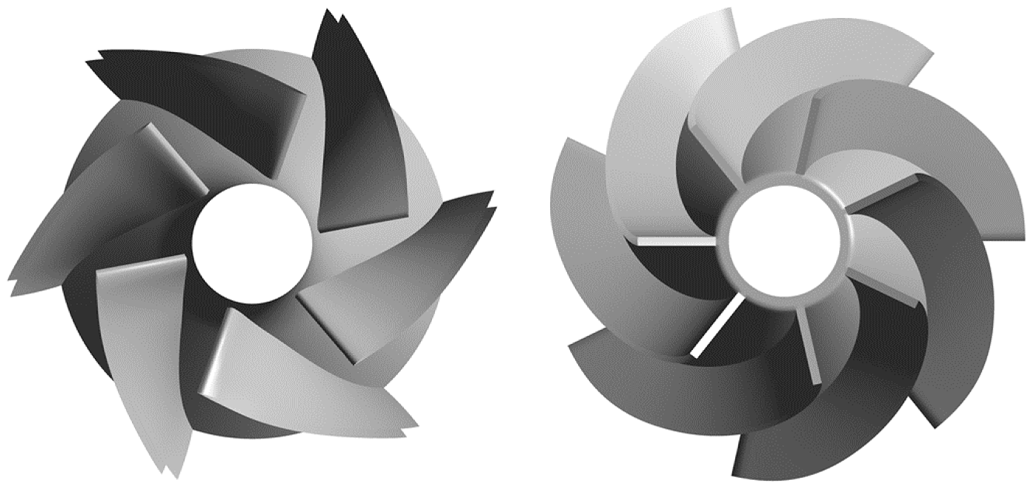
2. Geometry and Parameters

A typical mixed-flow centrifugal pump is taken as the subject of this article. The designed flow rate of this mixed-flow centrifugal pump is Q = 32 m3/h, and the designed head is H = 20 m. Compared with the traditional mixed-flow centrifugal pump, it adopts a higher design speed, which is 6000 r/min. The increase in design speed will inevitably lead to an increase in the rotor–stator interaction frequency between the rotor and the stator, which in turn will increase the possibility of vibration and noise in the pump system. Based on the above parameters, the specific speed [30] of this mixed-flow centrifugal pump can be found as:
n s = 3.65 n Q H 3 / 4 = 218.32
In general, the pumping chamber structure of centrifugal pumps includes two forms of diffuser and worm shell, and the pumping chamber structure of mixed-flow centrifugal pumps in this research uses a blade diffuser. Based on the existing literature, the number of blades of the impeller and diffuser has a large influence on the rotor–stator interaction characteristics within the model. The blade and vane numbers of the impeller and diffuser of this pump are Zi = 6 and Zd = 7, respectively, and the study of this mixed-flow centrifugal pump can be widely extended to other mixed-flow centrifugal pump models, which use a diffuser as the pressure chamber structure. Figure 1 shows the three-dimensional model of this mixed-flow centrifugal pump.

3. Numerical Modeling

3.1. Mathematical Model
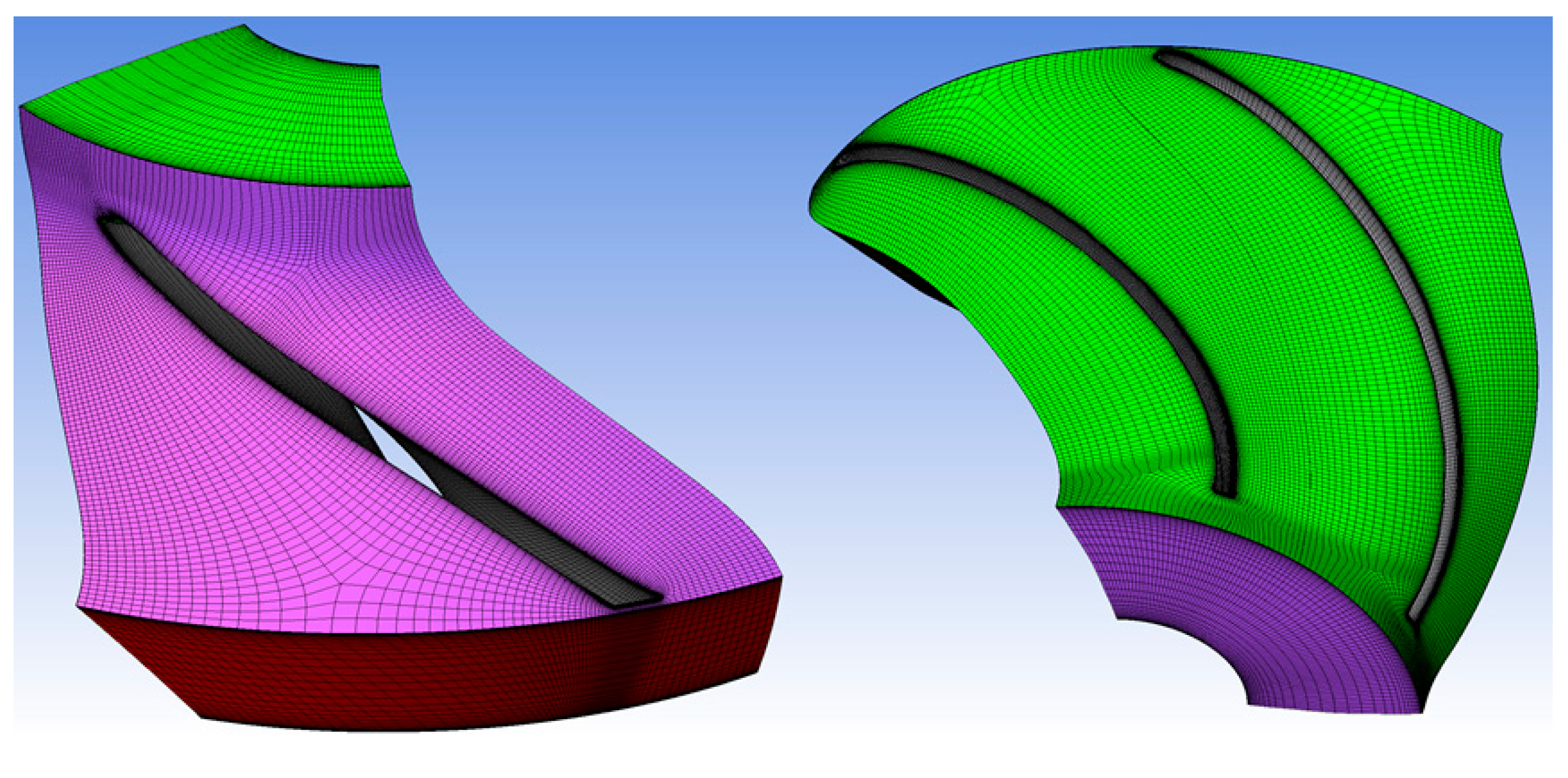
Most of the research analysis in this paper is based on numerical simulations, and the 3D modeling for numerical calculations is all performed in NX UG 10.0. The overall computational domain includes five subdomains: inlet section, impeller, chamber, diffuser, and outlet section. Among them, the length of the inlet and outlet sections is ten times the inlet diameter of the impeller, which not only helps to capture the coupling interference between the main flow and the return flow at the inlet position of the impeller, but also ensures that the outlet flow has enough space for evolution; the modeling of the impeller and diffuser needs to ensure the accuracy of the blade surface, thus reducing the system error caused by the modeling. At the same time, the clearance between the impeller and the chamber is not considered in the modeling process of the chamber, because the clearance of the end face at the impeller inlet is extremely small during the operation of the pump.

3.2. Grids

In order to improve the accuracy and convergence of the numerical calculations in this paper, the discretization of the computational domain is based on a hexahedral-structured grid. In addition, due to the high gradient of the variables in the near-wall region, boundary layers are applied at all locations near the solid wall in order to accurately capture the flow structure in the near-wall region. The near-wall surface turbulence modeling method used in this paper is the standard wall function, where the first grid height control rule of the boundary layer is related to the magnitude of the Reynolds number in the pump. The normal velocity has a very large velocity gradient at locations close to the wall. At very small distances, the velocity drops from relatively large values to the same velocity as the wall. In CFD, the dimensionless wall distance y+ is usually used to characterize the height of the first grid layer of the computational grid, and in the process of solving using the wall function, it is necessary to ensure that 30 < y+ < 300. Therefore, all grid solutions used in this study for numerical calculations are guaranteed to have a y+ value of around 50. The structured grids of the impeller and diffuser are generated using ANSYS TurboGrid, as shown in Figure 2.
In order to further avoid the influence of the grid on the accuracy of the calculation results, grid-independent verification work is carried out in this paper to obtain the optimal maximum grid control size ε. Figure 3 shows the variation of the numerically predicted head and efficiency of the mixed-flow centrifugal pump model as ε decreases. It is easy to see that as ε decreases, the overall grid size of the computational domain increases. When ε ≥ 1.3 mm, the numerical prediction of the head and efficiency decreases continuously, meanwhile, when ε ≤ 1.3 mm, the size change of the numerical prediction of the head and efficiency is smaller. Therefore, considering the accuracy of the numerical prediction results and the time period of numerical calculation, ε = 1.1 mm is chosen as the grid control method in this paper. At this time, the fluctuation of the numerical prediction of the pump head and efficiency is already less than 1%.

3.3. Boundary Conditions

The boundary conditions for the numerical calculation in this paper use the inlet total pressure with the outlet mass outflow recommended by ANSYS, which can enhance the convergence of the numerical calculation. The total pressure at the inlet position is set to Pref = 0 (Pa), and the mass flow rate at the outlet is adjusted according to the calculated working conditions. A no-slip wall is used for the solid wall surface in each calculation domain, but the roughness is considered. The roughness of the solid wall surface is set to 10 μm based on the surface roughness of the part used for testing in the study. Interface is used to connect and transfer data between each computational domain. The general connection is used for the intersection between two stationary computational domains, while the frozen rotor is used as the Frame Change Model for the intersection between the rotating computational domain (impeller) and the adjacent computational domain. The assembly model and boundary condition settings of the computational domain are shown in Figure 4.
In the deviation from the designed flow conditions operation, due to the fact that the impeller inlet medium’s incoming flow angle and the blade placement angle do not match, the impeller flow separation phenomenon will be obvious in the flow channel. This phenomenon largely determines the intensity of the secondary flow in the impeller runner, which in turn affects the intensity of the “wake/jet” at the impeller outlet position. Therefore, capturing the flow separation phenomenon in the impeller is the basis for accurate prediction of the rotor–stator interaction strength. Existing studies have shown that highly accurate prediction of flow separation can be achieved by turbulence models based on the k–ω equation, which solves two transport equations, one for the turbulent kinetic energy, k, and one for the turbulent frequency, ω. The two equations are [31]:
The k equation:
ρ k t + ρ U k = μ + μ t σ k k + P k + P k b β ρ k ω
and the ω equation:
ρ ω t + ρ U ω = μ + μ t σ ω ω + α ω k P k + P ω b β ρ ω 2
where μt is the turbulence viscosity; Pkb and Pωb represent the influence of the buoyancy forces; Pk is the production rate of turbulence. The other components are constants.
Among a series of turbulence models based on the k–ω equation, the SST model considers the transport of turbulent shear stress and provides highly accurate predictions of the onset and amount of flow separation under adverse pressure gradients [32,33]. Its proper transport of turbulent shear stress is constrained by a formulation of vortex viscosity expressed as follows [34]:
μ t / ρ = a 1 k m a x a 1 ω , S F 2
where F2 is a hybrid function that confines the limiter to the wall boundary layer; S is an invariant measure of the strain rate. Therefore, the SST turbulence model is chosen to carry out the numerical calculations in this paper.

4. Results and Discussion

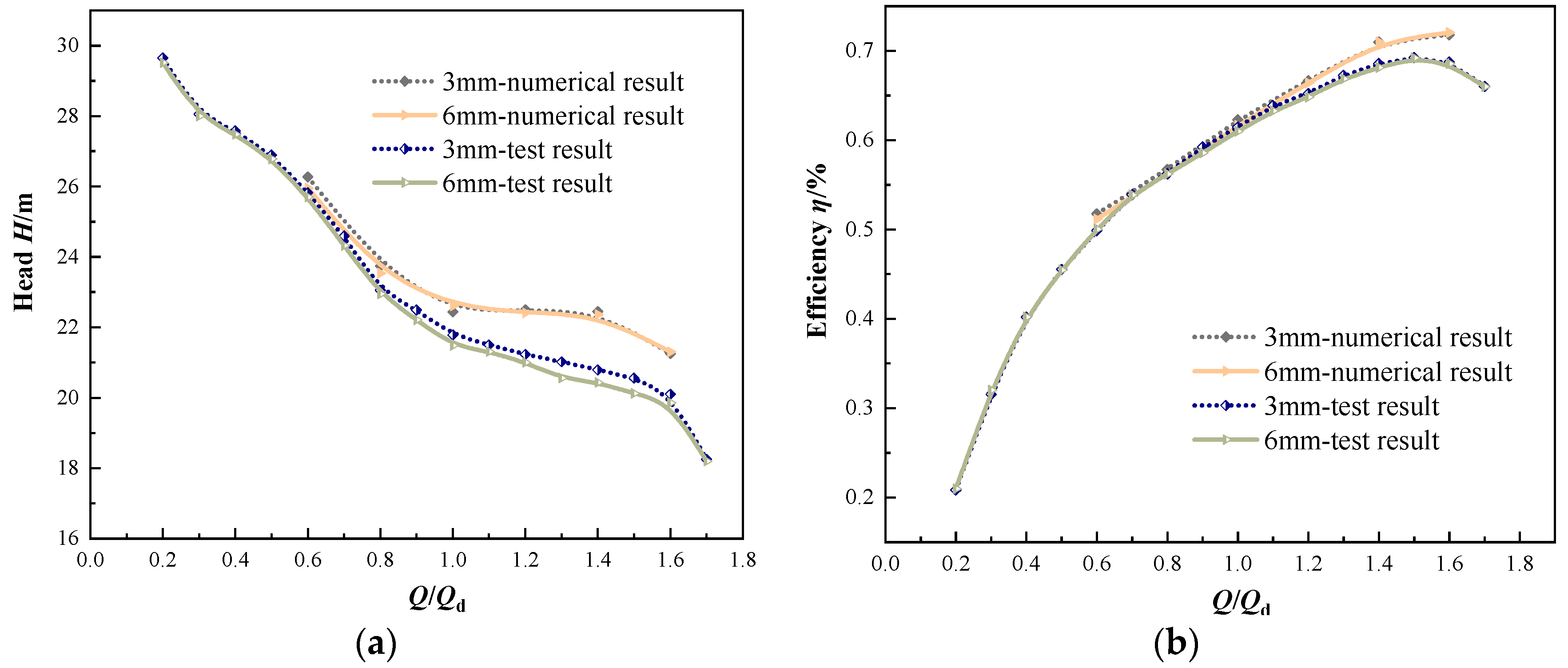
4.1. Pump Performance Validation

In order to verify the accuracy of the numerical calculation results in this paper, the performance test of the mixed-flow centrifugal pump model was carried out, and the test system is shown in Figure 5. The impeller and diffuser of the mixed-flow centrifugal pump in the test are processed by rapid prototyping technology. In the process of machining, the hub and the blade are integrated, and their physical models are shown in 1-1 and 1-2 of Figure 5. The shroud is machined separately and welded to the vane by laser heating and welding technology. This process can ensure the surface roughness of the impeller and diffuser, and at the same time, it is easy to check the accuracy of the channel during the process. During the experiment, the computer terminal sends out the start command, and the control cabinet completes the power start of the experimental system. The test bench uses an electromagnetic flowmeter to instantaneously monitor the flow rate of the pipeline, a torque meter to measure the shaft power of the pump, and an electronic pressure gauge to monitor the import and export pressure. The real-time pressure monitored by each instrument is transmitted to and summarized in the computer terminal equipped with the hydraulic test system software, and the computer completes the recording of experimental data, microconversion of speed, and pump performance calculation.
The model of mixed-flow centrifugal pump selected for this research has been used by an enterprise in Zhejiang, China, in actual production. During the development phase of this model, it was found that the vibration and noise of the mixed-flow centrifugal pump performance test system changes with the rotor–stator distance. Additionally, according to the geometry of the model, the rotor–stator distance of the pump is recommended to be less than or equal to 7.5 mm to match its own dimensions, not only to avoid material waste, but also to control the size of the space occupied by the pump in the system. The minimum value of the rotor–stator distance is selected considering the industrial manufacturing level and the operational safety of the pump. When the rotor–stator distance is less than 1.5 mm, the small axial displacement that may exist during the rotation of the impeller may cause it to rub against the diffuser. Therefore, the recommended range of rotor–stator distance is controlled within 1.5–7.5 mm.
Figure 6 shows the numerical predicted performance of the mixed-flow centrifugal pump with 3 mm and 6 mm rotor–stator distances compared with the experimental performance. The numerical predicted head is slightly higher than the experimental head for different rotor–stator distances in the small flow range (0.6Qd~0.8Qd), but the difference between the two values is less than 3%. The numerical prediction error at this point is mainly due to the unavoidable volume loss during the experimental process. As the flow rate increases, the numerical prediction error of the head is significantly larger than the prediction error of the head under the rated flow rate condition, but the numerical prediction error of the head is still less than 5%. The reason for the slight increase in the numerical prediction error at this point is that as the flow rate increases, the direction of the axial force on the impeller gradually changes from being opposite to the inlet flow to being the same as the inlet flow. This leads to a small shift of the impeller to the outlet direction in the experiment, and an increase in the end gap at the inlet position, which in turn leads to an increase in the pump volume loss. As the flow rate increases further, the numerical prediction error of the head increases further and reaches a maximum at 1.4Qd in the high flow rate range (1.2Qd~1.6Qd), when the axial deflection of the impeller reaches its maximum. At 1.6Qd, although the axial offset of the impeller is still at its maximum, the pump head is reduced, and the pressure difference between the front chamber and the impeller inlet position is also reduced; thus, the volume loss at this position is significantly lower compared to that at 1.4Qd. In the range of full flow conditions, the numerical prediction error of efficiency and the numerical prediction error of the head have the same variation rule, whereas in the small flow and rated flow conditions, the numerical prediction error is smaller, and in the large flow conditions, the numerical prediction error is larger.
Comparing the numerical prediction results with the experimental results under different rotor–stator distance, it can be found that the variation in rotor–stator distance has less effect on the pump performance. When the gap is 3 mm and 6 mm, there is no large difference in the maximum head, maximum flow rate, or efficiency of the pump; however, in the range of 1.0Qd~1.6Qd, the head and efficiency under the 6 mm gap are slightly lower than those under the 3 mm gap, which may be due to the change in the inlet flow angle of the diffuser with the change in rotor–stator distance, resulting in the head loss in the diffuser under the 6 mm gap becoming slightly increased. In summary, the numerical prediction of the performance of the mixed-flow centrifugal pump with different rotor–stator distances in this paper is in high agreement with the experimental results, and the numerical prediction of head and efficiency at full flow conditions is consistent with the experimental results. Therefore, the numerical calculation method in this paper has high accuracy for the numerical simulation of mixed-flow centrifugal pumps.

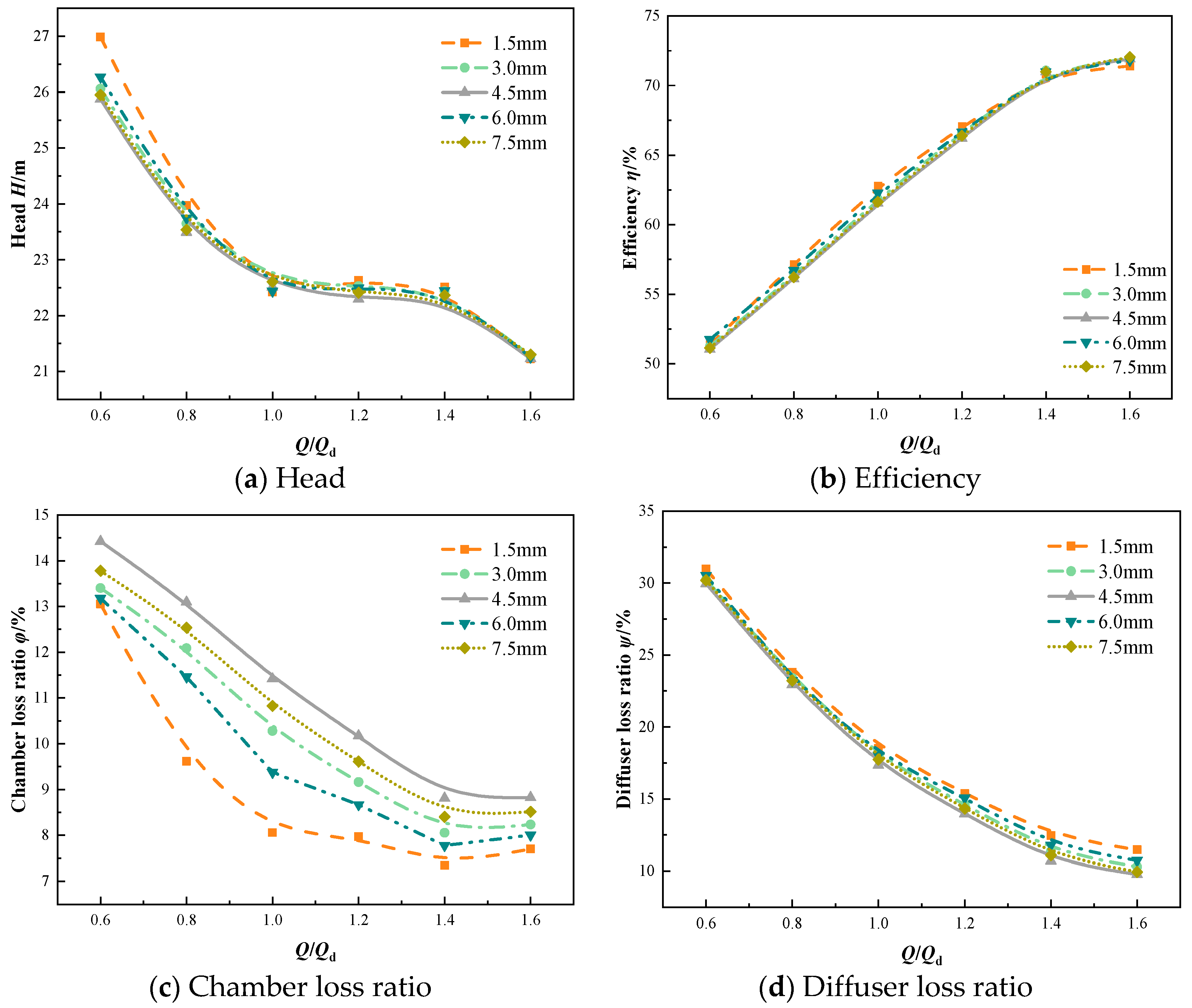
4.2. Performance Comparison with Different Rotor–Stator Distances

To further investigate the effect of rotor–stator distance variation on the performance of a mixed-flow centrifugal pump, the predicted results of the performance of a mixed-flow centrifugal pump are compared based on numerical simulations for rotor–stator distances ranging from 1.5 mm to 7.5 mm, using 1.5 mm as a study step, as shown in Figure 7. From Figure 7a, it can be seen that the head of the mixed-flow centrifugal pump under different rotor–stator distances remains basically the same under rated flow conditions and high flow conditions. However, at a low flow rate (especially 0.6Qd), there is a certain difference in the head under different rotor–stator distances; specifically, the head of the mixed-flow centrifugal pump under 1.5 mm rotor–stator distance is higher than for the other gaps. However, at 0.6Qd, the maximum standard deviation between the head of the 1.5 mm rotor–stator distance and the head of other distances is only 0.45 m. Therefore, the effect of the change in rotor–stator distance on the head of the mixed-flow centrifugal pump is small under the full flow condition. The efficiency comparison of the mixed-flow centrifugal pump with different rotor–stator distance in Figure 7b also shows that the change of rotor–stator distance has less effect on the performance of the mixed-flow centrifugal pump. At the same time, the maximum standard deviation of the efficiency is 0.52%, obtained at the design flow rate. Collectively, the head and efficiency of the mixed-flow centrifugal pump at each rotor–stator distance under full flow conditions do not vary greatly, and the mean values of their standard deviations are 0.16 m and 0.11%, respectively. Figure 7c,d presents our analytical results for the loss ratio in the chamber and the diffuser of the mixed-flow centrifugal pump, respectively; it was found that the main reason for the above difference in the performance of the mixed-flow centrifugal pump is the difference in the loss ratio in the chamber and the diffuser. It can be found that the loss ratio in the chamber under 1.5 mm rotor–stator distance is smaller than other solutions in the full flow condition range, which is the reason the pump efficiency is slightly higher under this rotor–stator distance. However, the loss ratio in the diffuser under 1.5 mm rotor–stator distance is slightly higher than the other solutions at full flow rate. This may be due to the closer distance between the impeller outlet and the diffuser inlet at 1.5 mm rotor–stator clearance, which leads to a lower matching between the inlet flow angle and the inlet placement angle of the diffuser, and increases the hydraulic loss in the diffuser. Therefore, the increase in rotor–stator distance leads to a slight increase in hydraulic loss in the chamber, while the hydraulic loss in the diffuser is slightly reduced. In the range of 1.5 mm to ~7.5 mm, the effect of rotor–stator distance change on the performance of mixed-flow centrifugal pump is small, and can be completely ignored in the project.

4.3. Flowfield Pattern with Different Rotor–Stator Distances

The previous paper explored the effect of rotor–stator distance on the performance of mixed-flow centrifugal pumps, and found that changing the rotor–stator distance in a certain range has minimal effect on the hydraulic performance of mixed-flow centrifugal pumps. However, in the axial flow centrifugal pump, the distance between the impeller and the diffuser as the core hydraulic components may have a certain effect on the rotor–stator interaction strength in the pump. Figure 8 shows a schematic diagram of the rotor–stator interaction in a mixed-flow centrifugal pump. The rotor–stator interaction between the rotating impeller and the stationary diffuser is mainly divided into three parts: the shock interaction caused by the impeller wake/jet impacting the diffuser, the wake interaction caused by the impeller wake transferring to the diffuser flow path, and the potential interaction caused by the upstream and downstream pressure waves propagating in the pump.
The velocity field distribution at the mid-span position in the chamber is shown in Figure 9. The velocity in the figure is expressed in dimensionless form, where V denotes the velocity component of the medium in the mid-span, and V2 denotes the circumferential velocity of the tip of the impeller as it rotates. It is easy to see that under the rated flow conditions, the high-speed jet at the impeller outlet has a significant intensity decay in the process of axial propagation. Specifically, with the increase in the distance from the impeller outlet, the range of the high-speed jet area on the circumference decreases. At 1.5 mm rotor–stator distance, the high-speed jet region develops directly from the impeller outlet to the diffuser inlet, and the impact intensity on the diffuser blade is greater. Therefore, under the rated flow conditions, the shock interaction intensity at 1.5 mm rotor–stator distance may be greater. Additionally, as the rotor–stator distance is raised, the high-speed jet has sufficient attenuation distance in the axial direction. As a result, the jet velocity impacting the diffuser is significantly reduced, which in turn significantly reduces the shock interaction in the pump. Moreover, the intensity of the jet phenomenon at the impeller outlet is significantly greater than that at rated flow rate. This is due to the mismatch between the inlet angle of the impeller and the incoming flow angle of the medium under low flow conditions, which increases the intensity of the secondary flow in the impeller flow path, and thus, enhances the jet intensity at the impeller outlet position [35,36,37]. In particular, at 1.5 mm rotor–stator distance, the high-speed jet region produces two high-speed regional cores near each diffuser blade. This may lead to its interference with each vane twice, making the frequency distribution of pressure pulsations in the pump more complex. However, as with the rated flow condition, the impact of the high-speed jet on the inlet region of the diffuser is significantly reduced after axial attenuation as the rotor–stator distances are increased. In the high flow condition, the effect of the rotor–stator distance on the high-speed jet region is significantly weakened. This is due to the fact that the axial velocity of the medium in the channel is bound to increase as the flow rate rises. Therefore, the decay rate of the high-speed jet region in the axial direction decreases. However, comparing the circumferential coverage of the high-speed jet region at the diffuser inlet, it can be seen that the strength of the high-speed jet at the diffuser inlet position with 7.5 mm rotor–stator distance is still significantly lower than that with 1.5 mm rotor–stator distance. Therefore, increasing the rotor–stator distance can significantly reduce the intensity of shock interaction in the pump.
Figure 10 shows the vorticity on the chamber mid-span. It is easy to see that the distribution of vorticity in the chamber can clearly show not only the influence of the impeller outlet jet on the downstream flowfield, but also the development of the wake region at the impeller outlet in the downstream flowfield. When the rotor–stator distance is 1.5 mm, the high vorticity region due to the jet extends from the impeller outlet to the diffuser inlet, which is consistent with the analysis in Figure 9. At this time, the high vorticity caused by the wake diffusion propagates to the inlet of the diffuser under different flow conditions. With the increase in the rotor–stator clearance, at 4.5 mm rotor–stator clearance, the high vorticity caused by the trailing diffusion only has a strong influence on the inlet position of the diffuser under the small flow condition. At 7.5 mm rotor–stator clearance, the high vorticity caused by the wake cannot be diffused to the inlet of the diffuser in all flow conditions. At the same time, comparing the distribution of vorticity in the chamber under different flow conditions, it can be found that the high vorticity at low flow conditions under each rotor–stator distance has the largest influence. This indicates that the wake interaction caused by low flow conditions is stronger, which is consistent with the phenomenon that the pump system is prone to vibration noise under low flow conditions in engineering practice. Therefore, increasing the rotor–stator distance can weaken the wake interaction intensity in the pump to a certain extent.
Figure 11 shows the pressure distribution on the mid-span midline in the chamber. The maximum variability of pressure in the circumferential distribution at different rotor–stator distances is observed at low flow conditions. The maximum value and minimum value of pressure in the circumferential direction at 1.5 mm clearance are the highest, with a difference of 56.9 kPa, while the difference between the maximum and minimum pressure amplitude gradually decreases with the increase in the rotor–stator distance, with an average value of 32.3 kPa. At the same time, the number of cycles of pressure change at 1.5 mm rotor–stator distance is significantly more than that at other rotor–stator distances. This indicates that when the rotor–stator distance is 1.5 mm, the pressure wave in the chamber under low flow conditions has the most complex propagation law on the circumference. At this time, the pressure wave amplitude is large and at high-frequency, making it easy to induce high-frequency and high-intensity pressure pulsation in the pump. As the rotor–stator distance is increased, the periodicity of the pressure in the circumferential distribution is more obvious, and the high value of the pressure in each cycle decreases and the low value increases, which is conducive to reducing the potential interaction intensity in the pump. In the rated flow condition and high flow condition, the periodicity of pressure circumferential distribution under 1.5 mm rotor–stator distance is obviously increased, but the extreme value of pressure in the circumferential direction under the 1.5 mm rotor–stator distance is still significantly larger than the extreme value of pressure in the circumferential direction under other rotor–stator distances. Additionally, the uniformity of the pressure in the circumferential distribution keeps improving with the increase in rotor–stator clearance. However, the small instability characteristic within the cycle still exists, indicating that the pressure in the circumferential distribution at the outlet of the impeller at smaller rotor–stator distances has more obvious unsteady characteristics. Therefore, increasing the rotor–stator distance can significantly reduce the potential interaction intensity in the pump, especially when the rotor–stator distance is small.
Figure 12 shows the pressure pulsation characteristics at different monitoring points in the chamber under the rated flow condition. It can be seen that the intensity of the pressure pulsation is significantly greater at Point 1, near the mid-span, than at the other two monitoring points. Additionally, comparing the time domain plots under different rotor–stator distance, it can be found that the time domain minima of pressure pulsation under the 1.5 mm rotor–stator distance are significantly smaller than those under other rotor–stator distance, which is consistent with the distribution of rotor–stator interaction intensity under rotor–stator distance in the previous paper. At the same time, it can be seen from the frequency domain plot that the pressure pulsation signal intensity of two times the impeller leaf frequency is also maximum at 1.5 mm rotor–stator distance, which is related to the fact that the pressure in the circumferential direction variation period is significantly more than at the other rotor–stator distances in Figure 11. At Point 2 and Point 3, the difference between the time domain extremes of pressure pulsation at different rotor–stator distances decreases significantly, and the difference in the intensity of the twofold impeller frequency signal in the frequency domain distribution also decreases. This is due to the fact that the monitoring points of Point 2 and Point 3 are far away from the rotor–stator interaction zone, and there is an obvious attenuation of the pressure pulsation signal in the propagation process. However, it is worth noting that at Point 2 and Point 3, the intensity of pressure pulsation at the 1.5 mm rotor–stator distance is still significantly greater than that at the other rotor–stator distances. Therefore, in engineering practice, too-small rotor–stator distances should be avoided to prevent inducing high-intensity pressure pulsation in the pump, which in turn, reduces the stability of the pump system.

5. Conclusions

In this paper, numerical calculations and experimental studies are carried out to determine the effect of rotor–stator distance on the performance of mixed-flow centrifugal pumps and the rotor–stator interaction strength. The accuracy of the numerical calculation method in the paper was verified experimentally; the performances of mixed-flow centrifugal pumps under different rotor–stator distances were compared, and the effect of rotor–stator distances on rotor–stator interaction strength was analyzed carefully. The main conclusions that can be extracted from this research are as follows:
(1)
The performance of the mixed-flow centrifugal pump at 3 mm and 6 mm rotor–stator distances was obtained experimentally. The comparison with the numerical prediction results shows that the numerical prediction results of the performance of the mixed-flow centrifugal pump at full flow conditions are in high agreement with the experimental results, and the numerical prediction of the head and efficiency at full flow conditions maintain the same variation pattern as the experimental results. This proves that the CFD method in this paper is highly accurate in obtaining the performance and flow pattern within the mixed-flow centrifugal pump.
(2)
As the rotor–stator distance increases, the flow loss ratio in the chamber of the mixed-flow centrifugal pump increases, which leads to a slight reduction in the shut-off point head and rated efficiency. The head and efficiency of the mixed-flow centrifugal pump at each rotor–stator distance under full flow conditions do not vary greatly; therefore, its performance is less affected by the rotor–stator distance at full flow conditions.
(3)
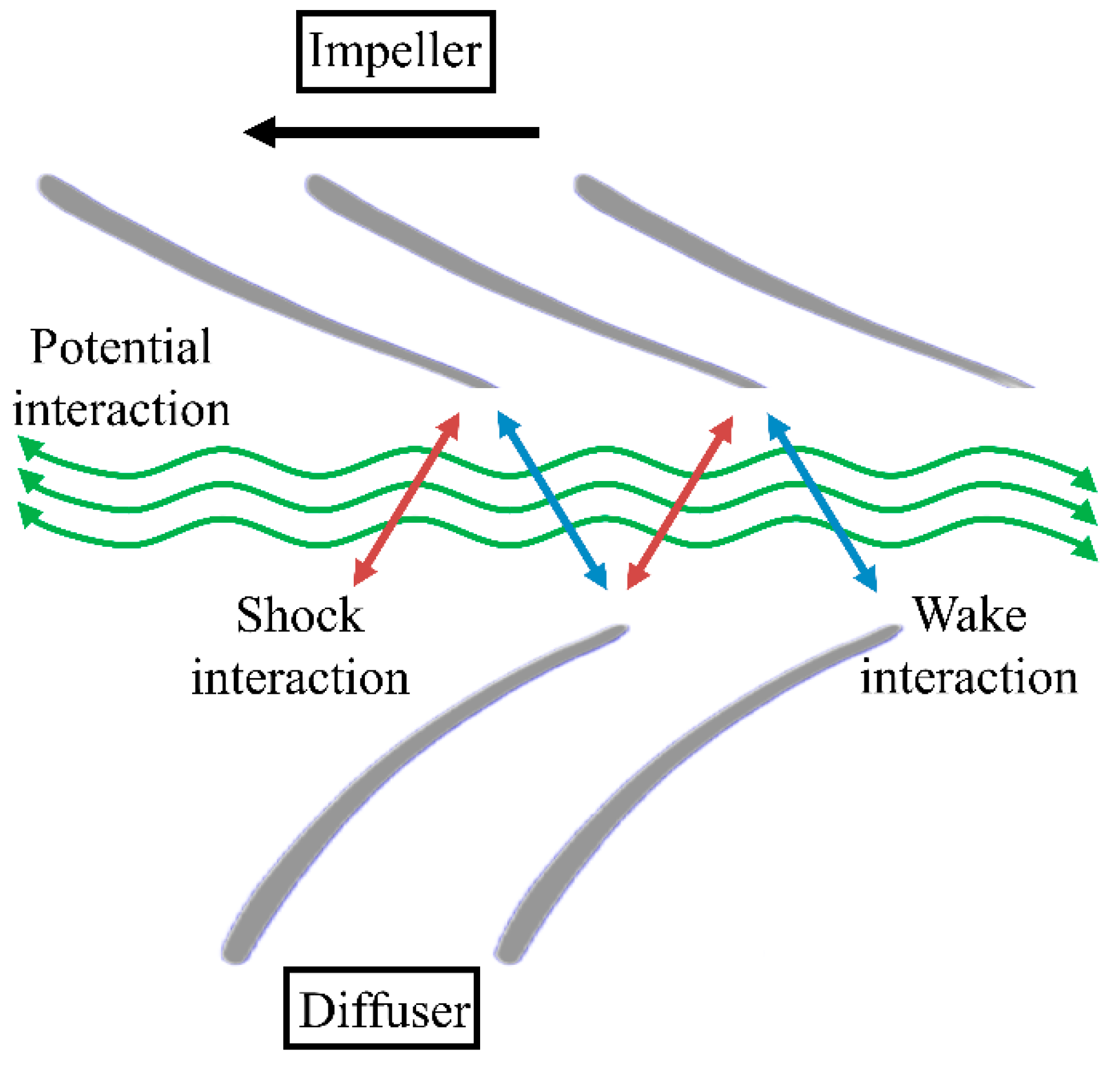
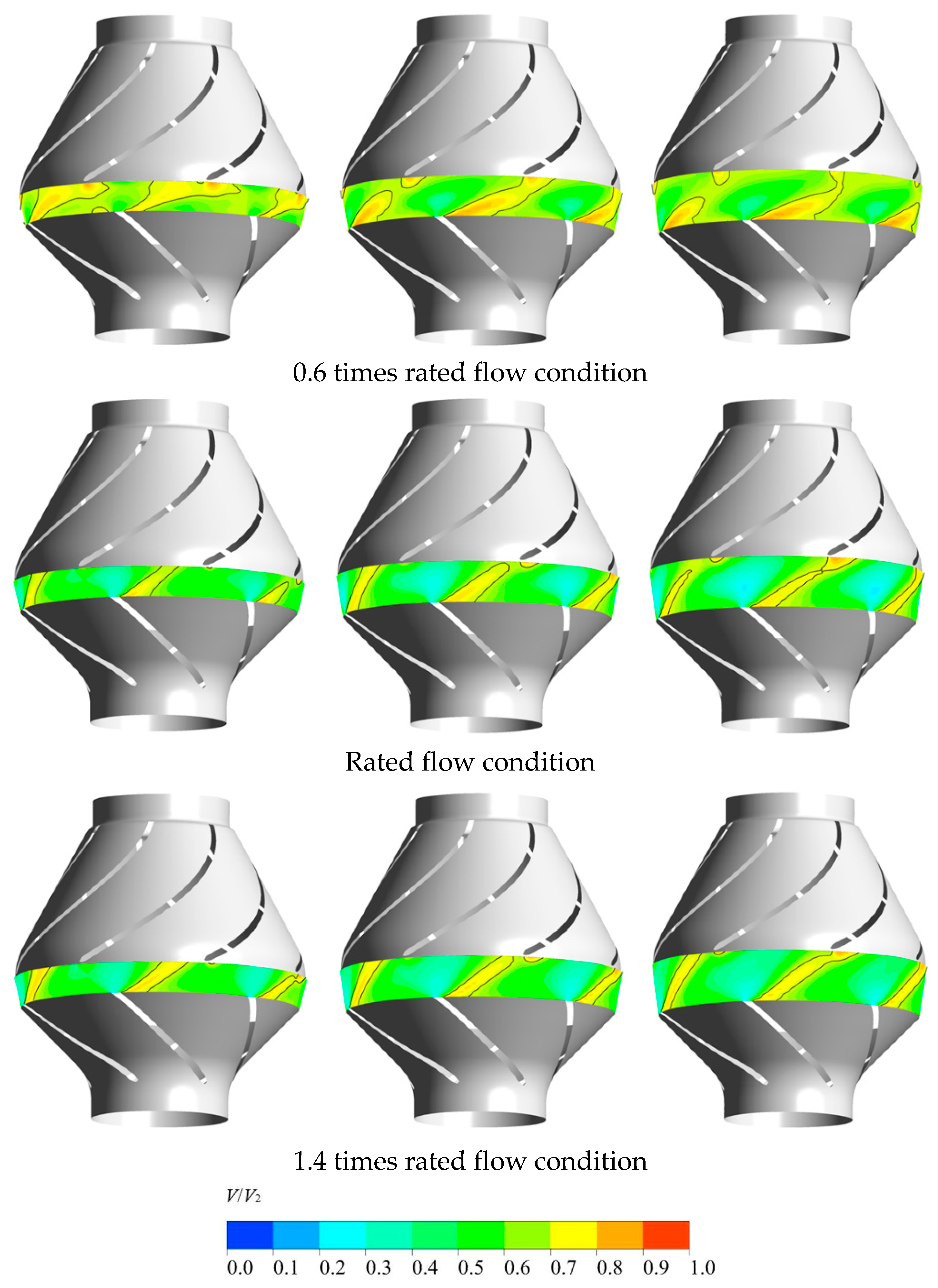
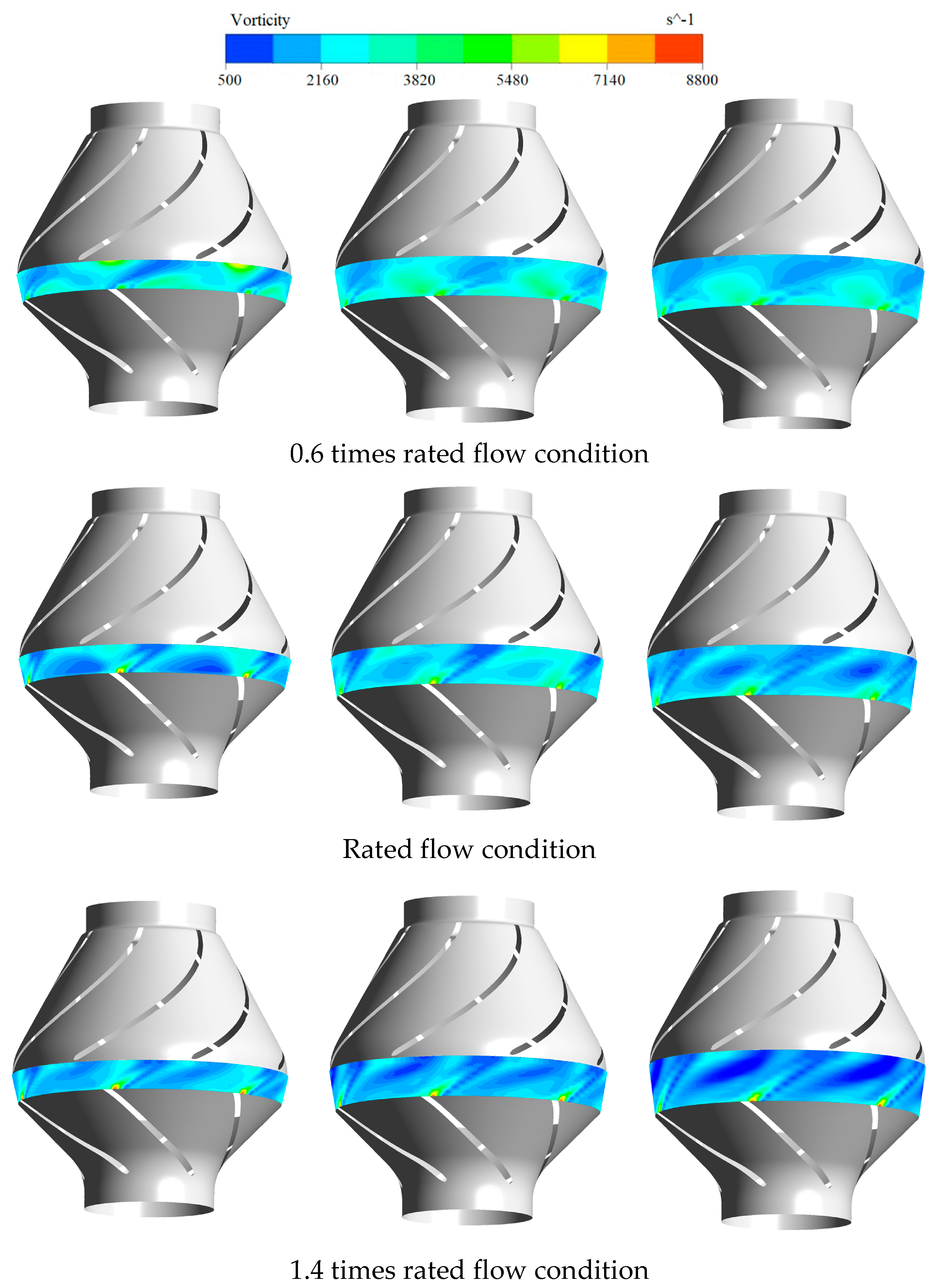
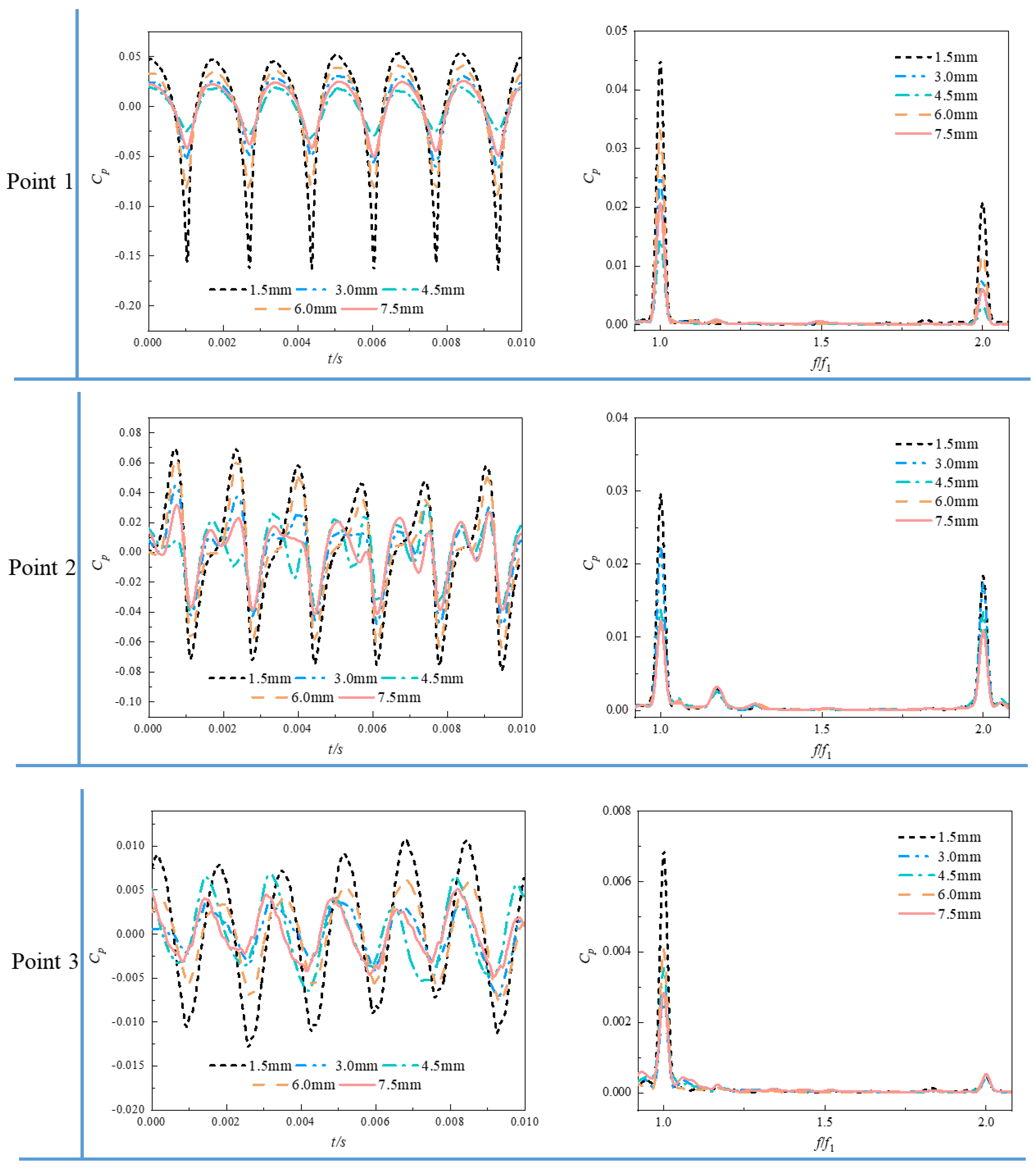
The jet velocity at the impeller outlet decays rapidly in the axial direction, so the impact strength of the jet on the diffuser blades decreases significantly with the increase in the rotor–stator distance. At the same time, the strength of the impeller outlet wake also decreases continuously during the propagation downstream. However, the wake interaction caused by low flow conditions is much stronger, which is consistent with the engineering practice of the pump system in the low flow conditions prone to vibration and noise. Therefore, avoiding the partial working condition operation of the pump device and appropriately enhancing the rotor–stator distance can significantly reduce the shock interaction and wake interaction intensity in the pump, which is conducive to the safe and stable operation of the pump device.
(4)
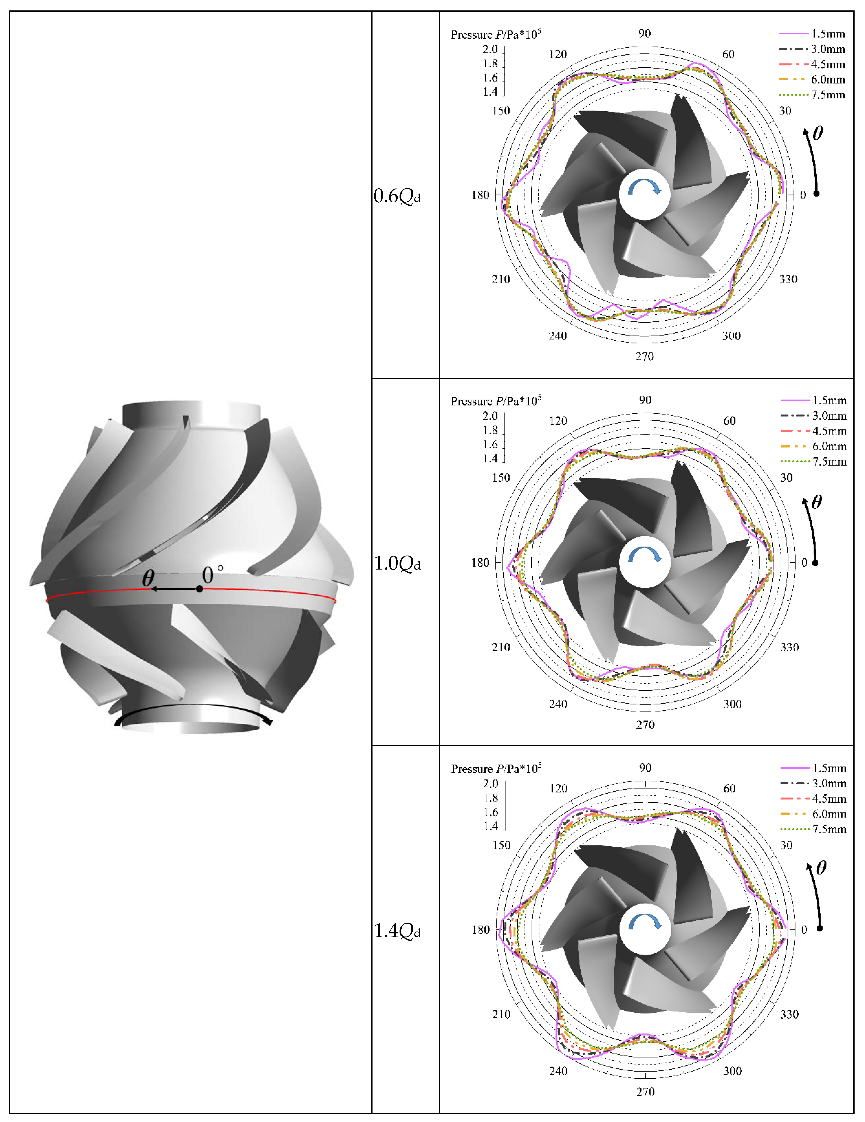
When the rotor–stator distance is 1.5 mm, the amplitude of pressure changes in the circumferential direction of the rotor–stator interaction zone is significantly greater than the amplitude of pressure change under other rotor–stator distances. When the rotor–stator distance is raised, the number of pressure change cycles is consistent with the number of impeller blades, and the amplitude of pressure change in the circumferential direction is significantly reduced. Therefore, the rotor–stator distance elevation can reduce the intensity of potential interaction in the pump. In engineering practice, too-small rotor–stator distances should be avoided to prevent the induction of high-frequency resonance in the pump system.
(5)
Based on the present study, we believe that increasing the rotor–stator distance can reduce the rotor–stator interaction intensity in the pump, weaken the internal pressure pulsation phenomenon, and thus, improve the operational stability of the pump system while keeping the pump system performance basically unchanged. The results of this study can be extended to all centrifugal pumps using diffusers in the form of vanes as the pressure chamber, which has strong practical application and theoretical value.
(6)
However, the work conducted so far in this paper is still insufficient for revealing the detailed mechanism of rotor–stator interference in mixed-flow centrifugal pumps. For example, the local energy loss due to unsteady interference flow caused by different rotor–stator distances is not yet clear. At the same time, the coupling relationship between the rotor–stator interference of the pump chamber and the flow characteristics of the medium has not been studied. Therefore, the above deficiencies will be the target of future research to explore the energy and flow characteristics of the pump device under different rotor–stator interference conditions, and continue to improve the theory related to rotor–stator interference of pumps.

Author Contributions

Conceptualization, F.H. and Y.Y.; methodology, F.H. and X.C.; software, Y.Y.; formal analysis, F.H.; writing—original draft preparation, F.H. and X.C.; writing—review and editing, Y.Y. and C.W.; supervision, C.W. All authors have read and agreed to the published version of the manuscript.

Funding

This work was supported by the Youth Fund Project of Natural Science Foundation of Jiangsu Province (Grand No. BK20220587).

Institutional Review Board Statement

Not applicable.

Informed Consent Statement

Not applicable.

Acknowledgments

Not applicable.

Conflicts of Interest

The authors declare no conflict of interest.

Symbols

Qflow rate
Qddesigned flow rate
Hhead
nrotating speed
φchamber loss ratio
Ziblade number of impeller
Zdvane number of diffuser
εmaximum grid control size
μtturbulence viscosity
kturbulent kinetic energy
ωturbulent frequency
Ppressure
Pkbinfluence of the buoyancy forces in turbulent kinetic energy
Pωbinfluence of the buoyancy forces in turbulent frequency
Pkproduction rate of turbulence

Abbreviations

CFDcomputational fluid dynamics
FFTfast Fourier transform
BPFblade passing frequency

References

  1. Kim, J.H.; Ahn, H.J.; Kim, K.Y. High-efficiency design of a mixed-flow centrifugal pump. Sci. China Ser. E Technol. Sci. 2010, 53, 24–27. [Google Scholar] [CrossRef]
  2. Muggli, F.A.; Holbein, P.; Dupont, P. CFD calculation of a mixed flow pump characteristic from shutoff to maximum flow. J. Fluids Eng. 2002, 124, 798–802. [Google Scholar] [CrossRef]
  3. Li, W.; Li, E.; Ji, L.; Zhou, L. Mechanism and propagation characteristics of rotating stall in a mixed-flow centrifugal pump. Renew. Energy 2020, 153, 74–92. [Google Scholar] [CrossRef]
  4. Al-Obaidi, A.R. Detection of cavitation phenomenon within a centrifugal pump based on vibration analysis technique in both time and frequency domains. Exp. Tech. 2020, 44, 329–347. [Google Scholar] [CrossRef]
  5. Wang, C.L.; Jia, F.; Wu, Z.W.; Liu, D. Pressure fluctuation of unsteady flow in high specific speed mixed-flow centrifugal pump. J. Drain. Irrig. Mach. Eng. 2013, 31, 103–108. [Google Scholar]
  6. Miyabe, M.; Maeda, H.; Umeki, I.; Jittani, Y. Unstable head-flow characteristic generation mechanism of a low specific speed mixed flow pump. J. Therm. Sci. 2006, 15, 115–120. [Google Scholar] [CrossRef]
  7. Wang, K.; Liu, H.; Zhou, X.; Wang, W. Experimental research on pressure fluctuation and vibration in a mixed flow pump. J. Mech. Sci. Technol. 2016, 30, 179–184. [Google Scholar] [CrossRef]
  8. Al-Obaidi, A.R.; Mishra, R. Experimental investigation of the effect of air injection on performance and detection of cavitation in the centrifugal pump based on vibration technique. Arab. J. Sci. Eng. 2020, 45, 5657–5671. [Google Scholar] [CrossRef]
  9. Al-Obaidi, A.R. Experimental comparative investigations to evaluate cavitation conditions within a centrifugal pump based on vibration and acoustic analyses techniques. Arch. Acoust. 2020, 45, 541–556. [Google Scholar]
  10. Al-Obaidi, A.R. Experimental investigation of the effect of suction valve opening on the performance and detection of cavitation in the centrifugal pump based on acoustic analysis technique. Arch. Acoust. 2019, 44, 59–69. [Google Scholar]
  11. Miyabe, M.; Furukawa, A.; Maeda, H.; Umeki, I.; Jittani, Y. A behavior of the diffuser rotating stall in a low specific speed mixed-flow centrifugal pump. Int. J. Fluid Mach. Syst. 2009, 2, 31–39. [Google Scholar] [CrossRef]
  12. Liu, M.; Tan, L.; Liu, Y.; Xu, Y.; Cao, S. Large eddy simulation of cavitation vortex interaction and pressure fluctuation around hydrofoil ALE 15. Ocean Eng. 2018, 163, 264–274. [Google Scholar] [CrossRef]
  13. Wang, C.; He, X.; Shi, W.; Wang, X.; Wang, X.; Qiu, N. Numerical study on pressure fluctuation of a multistage centrifugal pump based on whole flow field. AIP Adv. 2019, 9, 035118. [Google Scholar] [CrossRef]
  14. Miyabe, M.; Furukawa, A.; Maeda, H.; Umeki, I. Investigation of internal flow and characteristic instability of a mixed flow pump. In Proceedings of the Fluids Engineering Division Summer Meeting, Vail, CO, USA, 2–6 August 2009; Volume 43727, pp. 315–321. [Google Scholar]
  15. Al-Obaidi, A.R. Investigation of effect of pump rotational speed on performance and detection of cavitation within a centrifugal pump using vibration analysis. Heliyon 2019, 5, e01910. [Google Scholar] [CrossRef] [PubMed]
  16. Van Esch, B.; Cheng, L. Unstable operation of a mixed-flow centrifugal pump and the influence of tip clearance. In Proceedings of the ASME-JSME-KSME Joint Fluids Engineering Conference, Shizuoka, Japan, 24–29 July 2011; Volume 44403, pp. 79–87. [Google Scholar]
  17. Funakoshi, H.; Tsukamoto, H.; Miyazaki, K.; Miyagawa, K. Experimental study on unstable characteristics of mixed-flow centrifugal pump at low flow-rates. In Proceedings of the ASME/JSME 2003 4th Joint Fluids Summer Engineering Conference, Honolulu, HI, USA, 6–10 July 2003; Volume 36975, pp. 609–614. [Google Scholar]
  18. Nagahara, T. Application of PIV for the flow field measurement in a mixed-flow centrifugal pump. In IOP Conference Series. Earth and Environmental Science; IOP Publishing: Bristol, UK, 2012; p. 15. [Google Scholar]
  19. Dring, R.; Joslyn, H.; Hardin, L.; Wagner, J.H. Turbine rotor-stator interaction. ASME J. Eng. Gas. Turbines Power 1982, 104, 729–742. [Google Scholar] [CrossRef]
  20. Joslyn, D.; Dring, R. Three-dimensional flow in an axial turbine: Part 1—Aerodynamic mechanisms. ASME J. Turbomach. 1992, 114, 61–70. [Google Scholar] [CrossRef]
  21. Iino, T.; Kasai, K. An analysis of unsteady flow induced by interaction between a centrifugal impeller and a vaned diffuser. Trans. Jpn. Soc. Mech. Eng. 1985, 51, 154–159. [Google Scholar]
  22. Al-Obaidi, A.R. Numerical investigation of flow field behaviour and pressure fluctuations within an axial flow pump under transient flow pattern based on CFD analysis method. In Journal of Physics: Conference Series; IOP Publishing: Bristol, UK, 2019; Volume 1279, p. 012069. [Google Scholar]
  23. Shi, F.; Tsukamoto, H. Numerical study of pressure fluctuations caused by impeller-diffuser interaction in a diffuser pump stage. ASME J. Fluids Eng. 2001, 123, 466–474. [Google Scholar] [CrossRef]
  24. Al-Obaidi, A.R.; Mohammed, A.A. Numerical Investigations of Transient Flow Characteristic in Axial Flow Pump and Pressure Fluctuation Analysis Based on the CFD Technique. J. Eng. Sci. Technol. Rev. 2019, 12, 70–79. [Google Scholar] [CrossRef]
  25. Zhang, M.; Tsukamoto, H. Unsteady hydrodynamic forces due to rotor-stator interaction on a diffuser pump with identical number of vanes on the impeller and diffuser. ASME J. Fluids Eng. 2005, 127, 743–751. [Google Scholar] [CrossRef]
  26. Al-Obaidi, A.R. Investigation of the influence of various numbers of impeller blades on internal flow field analysis and the pressure pulsation of an axial pump based on transient flow behavior. Heat Transf. 2020, 49, 2000–2024. [Google Scholar] [CrossRef]
  27. Barrio, R.; Parrondo, J.; Blanco, E. Numerical analysis of the unsteady flow in the near-tongue region in a volute-type centrifugal pump for different operating points. Comput. Fluids 2010, 39, 859–870. [Google Scholar] [CrossRef]
  28. Yang, Y.; Zhou, L.; Shi, W.; He, Z.; Han, Y.; Xiao, Y. Interstage difference of pressure pulsation in a three-stage electrical submersible pump. J. Pet. Sci. Eng. 2021, 196, 107653. [Google Scholar] [CrossRef]
  29. Yang, Y.; Zhou, L.; Han, Y.; Hang, J.; Lv, W.; Shi, W.; He, Z.; Pan, B. Pressure pulsation investigation in an electrical submersible pump based on Morlet continuous wavelet transform. Proc. Inst. Mech. Eng. Part C J. Mech. Eng. Sci. 2021, 235, 6069–6079. [Google Scholar] [CrossRef]
  30. Karassik, I.J.; Messina, J.P.; Cooper, P.; Heald, C.C. Pump Handbook; McGraw-Hill Education: New York, NY, USA, 2008. [Google Scholar]
  31. Menter, F.R.; Kuntz, M.; Langtry, R. Ten years of industrial experience with the SST turbulence model. Turbul. Heat Mass Transf. 2003, 4, 625–632. [Google Scholar]
  32. Versteeg, H.K.; Malalasekera, W. An Introduction to Computational Fluid Dynamics: The Finite Volume Method; Pearson Education: London, UK, 2007. [Google Scholar]
  33. Bradshaw, P. An Introduction to Turbulence and Its Measurement: Thermodynamics and Fluid Mechanics Series; Elsevier: Amsterdam, The Netherlands, 2013. [Google Scholar]
  34. Dhakal, T.P.; Walters, D.K. A three-equation variant of the SST k-ω model sensitized to rotation and curvature effects. J. Fluids Eng. 2011, 133, 111201. [Google Scholar] [CrossRef]
  35. Zhang, D.; Wang, H.; Liu, J.; Wang, C.; Ge, J.; Zhu, Y.; Chen, X.; Hu, B. Flow characteristics of oblique submerged impinging jet at various impinging heights. J. Mar. Sci. Eng. 2022, 10, 399. [Google Scholar] [CrossRef]
  36. Hu, B.; Wang, H.; Liu, J.; Zhu, Y.; Wang, C.; Ge, J.; Zhang, Y. A numerical study of a submerged water jet impinging on a stationary wall. J. Mar. Sci. Eng. 2022, 10, 228. [Google Scholar] [CrossRef]
  37. Li, W.; Yang, Z.; Shi, W.; Li, E.; Ji, L. Research progress of non-uniform inflow of water jet pump. J. Drain. Irrig. Mach. Eng. 2022, 40, 757–765. [Google Scholar]
Figure 1. Three-dimensional model of mixed-flow centrifugal pump.
Jmse 10 01114 g001
Figure 2. Grid details of the impeller and diffuser.
Jmse 10 01114 g002
Figure 3. Grid independence analysis.
Jmse 10 01114 g003
Figure 4. Computational domain model and boundary conditions.
Jmse 10 01114 g004
Figure 5. Test bench system: 1. mixed-flow centrifugal pump, 1-1. diffuser, 1-2. impeller; 2. shaft coupling; 3. torque meter; 4. motor; 5. torque and RPM digital display; 6. electronic pressure gauge; 7. electromagnetic flowmeter; 8. electric valve; 9. computer; 10. test control system; 11. water pool.
Jmse 10 01114 g005
Figure 6. Comparison of experimental and numerical results: (a) head; (b) efficiency.
Jmse 10 01114 g006
Figure 7. Comparison of performance with different rotor–stator distances.
Jmse 10 01114 g007
Figure 8. Schematic of rotor–stator interaction.
Jmse 10 01114 g008
Figure 9. Velocity distribution at mid-span position within the chamber: rotor–stator distance = 1.5 mm; rotor–stator distance = 4.5 mm; rotor–stator distance = 7.5 mm.
Jmse 10 01114 g009
Figure 10. Vorticity distribution at mid-span position within the chamber: rotor–stator distance = 1.5 mm; rotor–stator distance = 4.5 mm; rotor–stator distance = 7.5 mm.
Jmse 10 01114 g010
Figure 11. Pressure distribution on the mid-span midline within the chamber.
Jmse 10 01114 g011
Figure 12. Pressure pulsation characteristics within the chamber under rated flow condition.
Jmse 10 01114 g012
Publisher’s Note: MDPI stays neutral with regard to jurisdictional claims in published maps and institutional affiliations.

