Optimization of Guide Vane Centrifugal Pumps Based on Response Surface Methodology and Study of Internal Flow Characteristics
Abstract
:1. Introduction
2. Physical Model and Simulation Method
2.1. Structure and Basic Parameters
2.2. Numerical Simulation Configuration
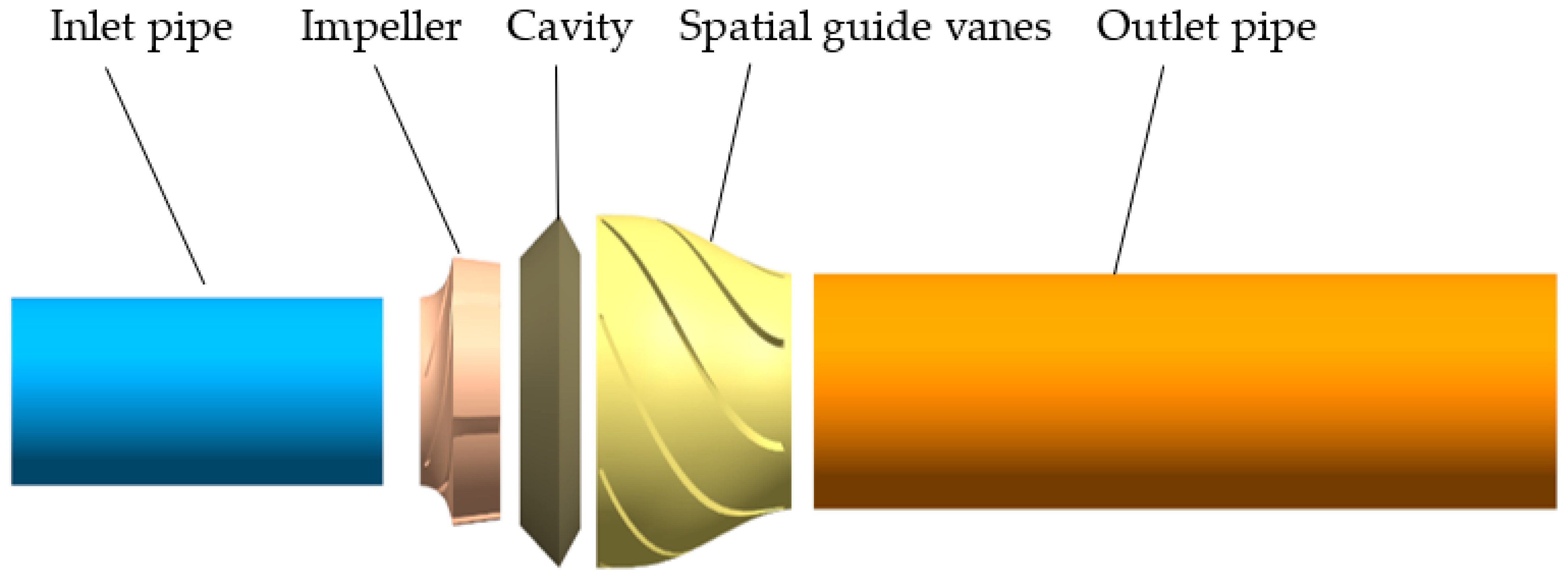
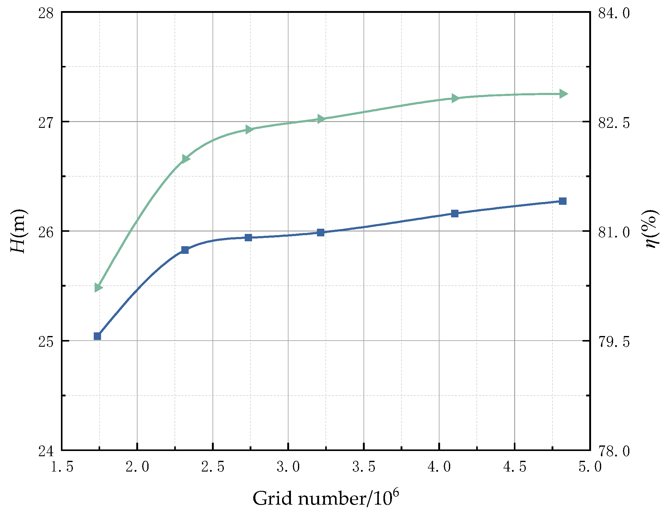
2.3. Simulation Domain and Mesh
3. Experimental Validation
3.1. Experimental Equipment
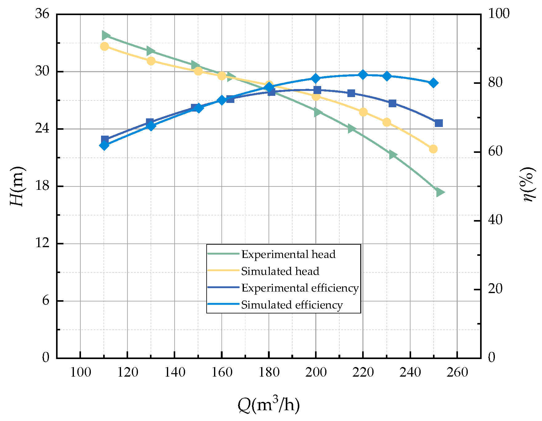
3.2. External Characteristic Test Results
4. Response Surface Optimization Analysis
4.1. Mathematical Model
4.2. Response Surface Experimental Design and Results
4.3. Model Fitting and Response Surface Analysis
4.4. Analysis of Factor Significance
4.5. Analysis of Optimization Results
5. Internal Flow Characteristics of the Guide Vane Centrifugal Pump
5.1. Pressure Distribution and Streamlines
5.2. Internal Pressure Pulsation in the Pump
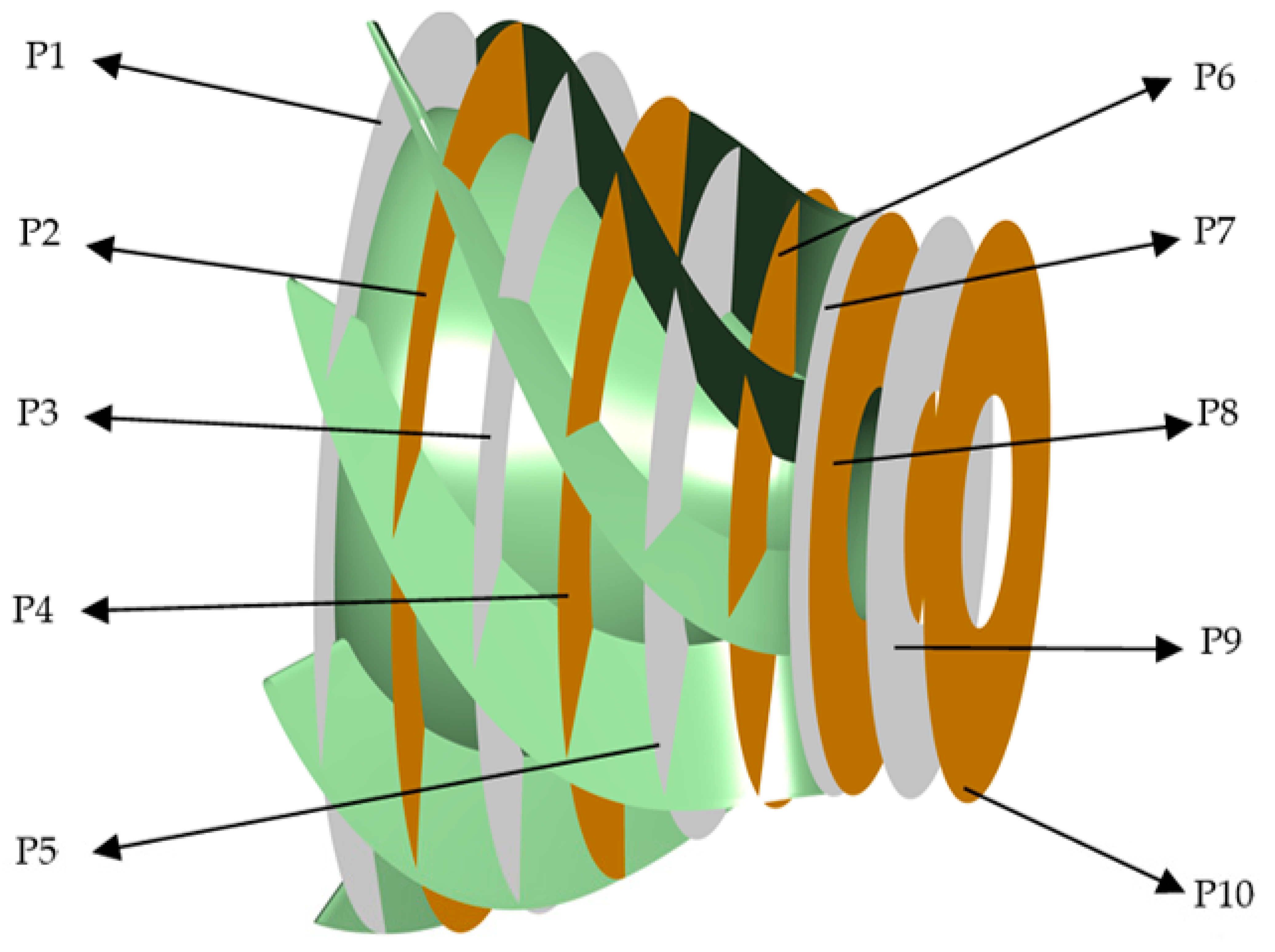
5.2.1. Pressure Pulsation Monitoring Point Configuration
5.2.2. Time-Domain Analysis of Pressure Pulsation
5.2.3. Pressure Pulsation Frequency Domain Analysis
5.3. Entropy Generation Analysis
5.3.1. Entropy Generation Theory
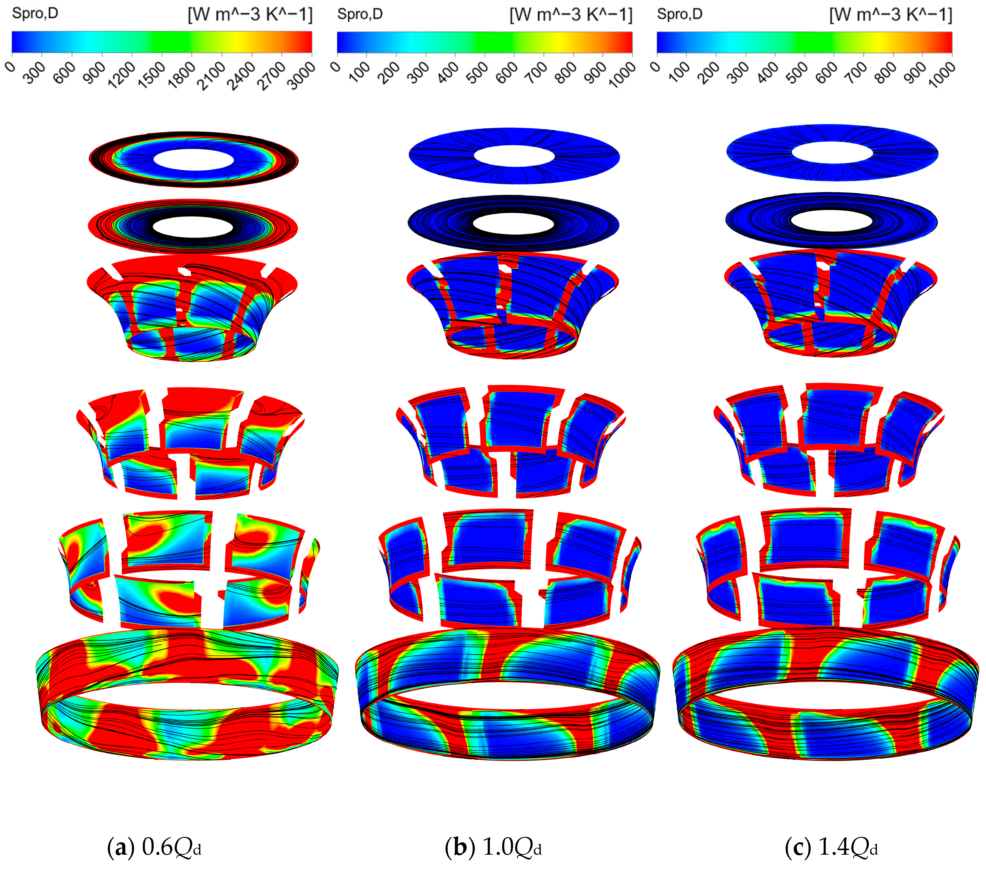
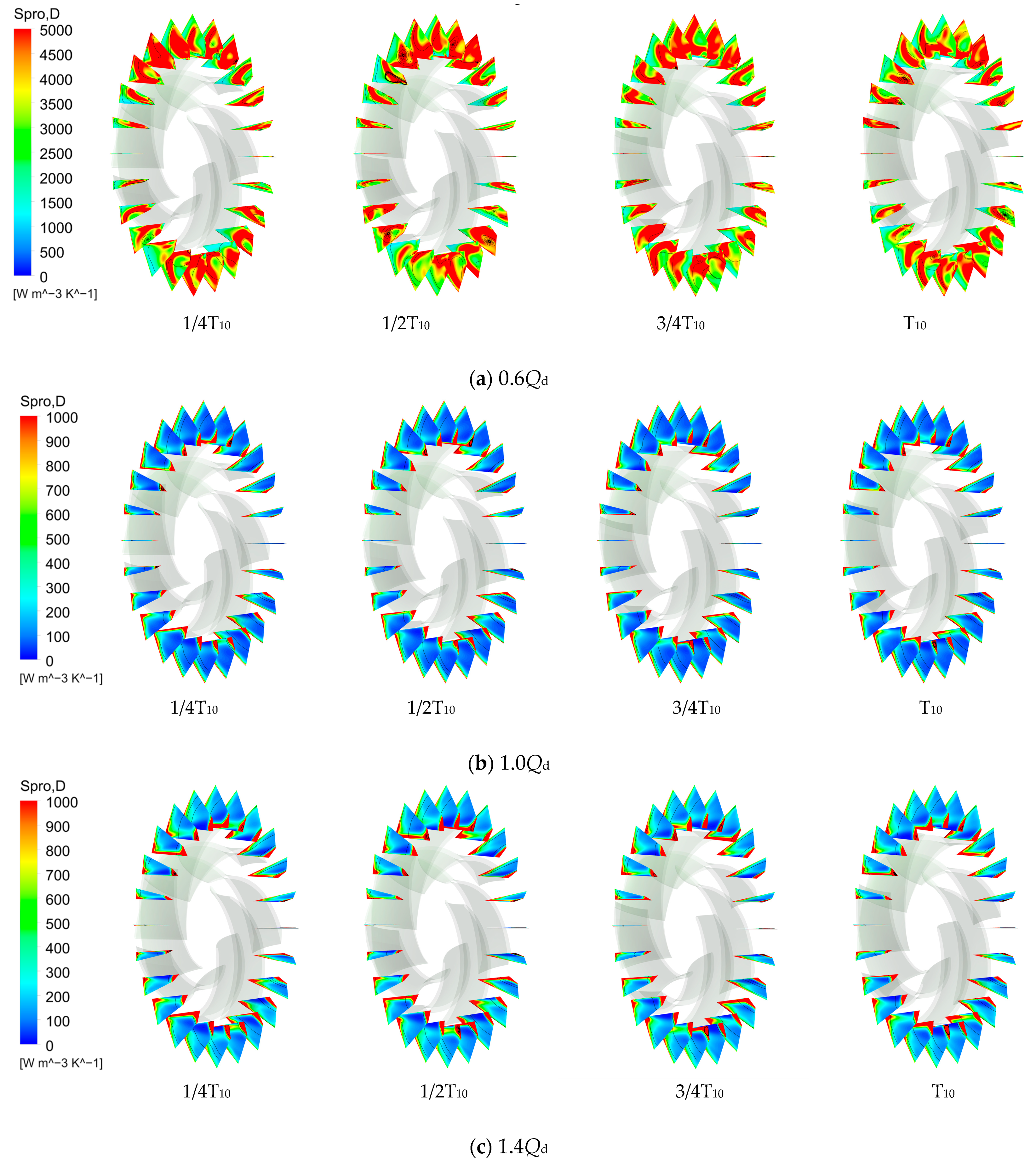
5.3.2. Analysis of Flow and Entropy Generation within the Impeller
5.3.3. Internal Flow and Entropy Generation Analysis within the Cavity
5.3.4. Analysis of Internal Flow and Entropy Generation in Guide Vane
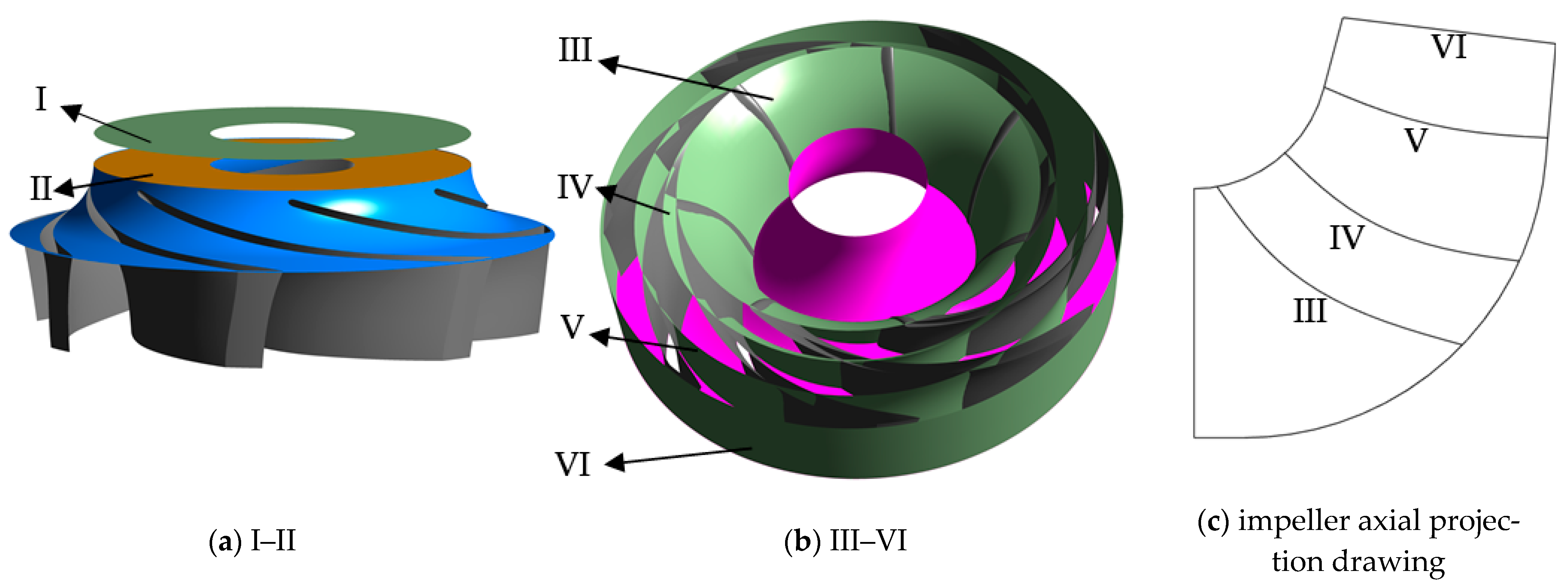
5.3.5. Analysis of Entropy Generation in Flow Components
6. Conclusions
- (1)
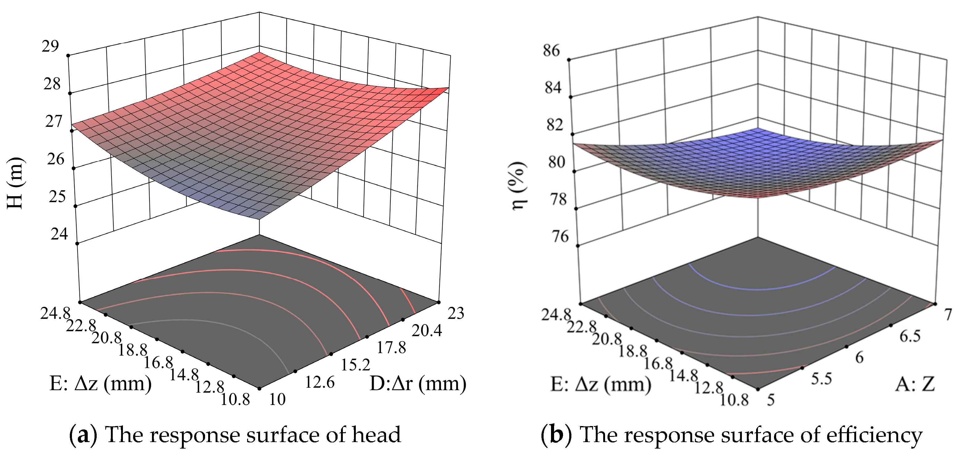
- The guide vane centrifugal pump was selected as the research subject, and the number of blades, blade wrap angle, blade outlet angle, and axial and radial distances between the guide vane and impeller were considered as design variables. The pump head and efficiency were treated as response variables. Based on the Box–Behnken design method and CFX numerical simulation results, the function equation between design variables and response variables was obtained. Additionally, the influence of each factor on the response variables was analyzed. It was observed that all five single-factor variables had a significant impact on the head and efficiency. There are interactions among the factors, however; compared to single factor and single-factor quadratic, two-factor interaction terms are less significant.
- (2)
- Based on the RSM, a quadratic polynomial equation was established, and it was found that the optimal combination of guide vane centrifugal structural parameters is Z = 7, β2 = 23.8°, φ1 = 100.7°, ∆r = 22.814 mm, and ∆z = 13.838 mm. The simulated values of the original model and the optimized model are in close agreement with the predicted values from the RSM. Additionally, the optimized model exhibits an increase of 2.5845 m in head and a 2.88% improvement in efficiency compared to the original model. This indicates that the RSM is capable of accurately reflecting the complex nonlinear relationships between the structural parameters of the guide vane centrifugal pump and the optimization objectives. It provides an intuitive and effective optimization approach for the design of guide vane centrifugal pumps.
- (3)
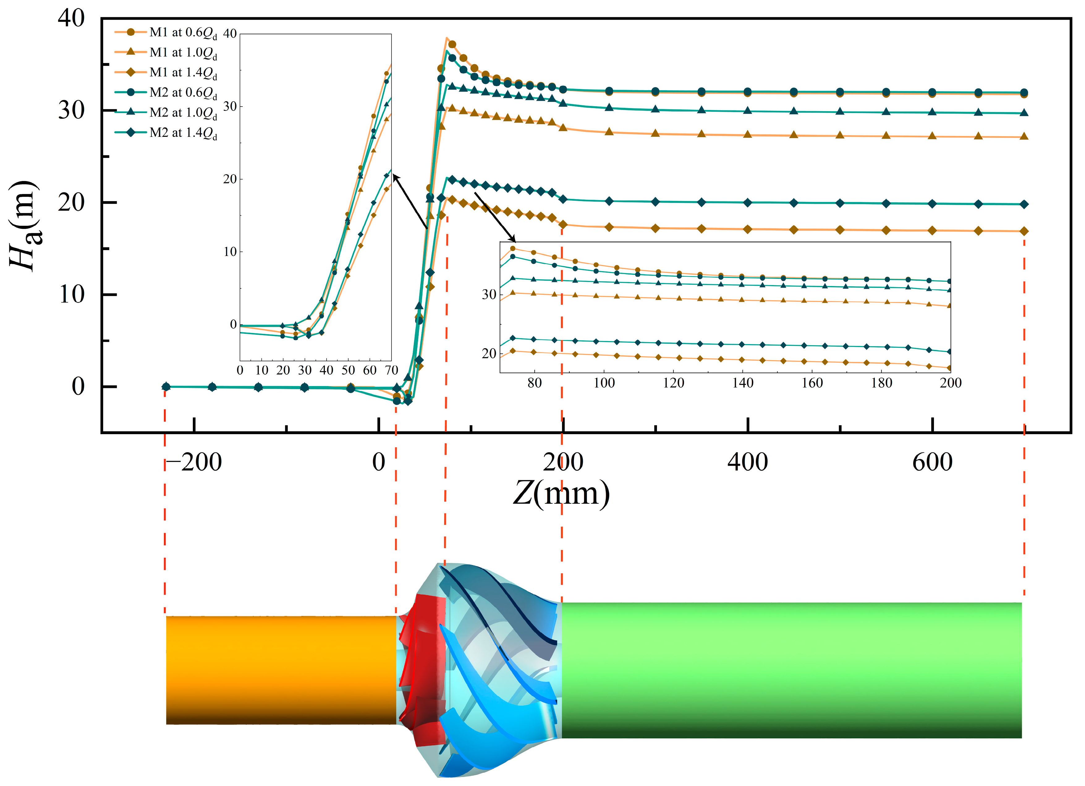
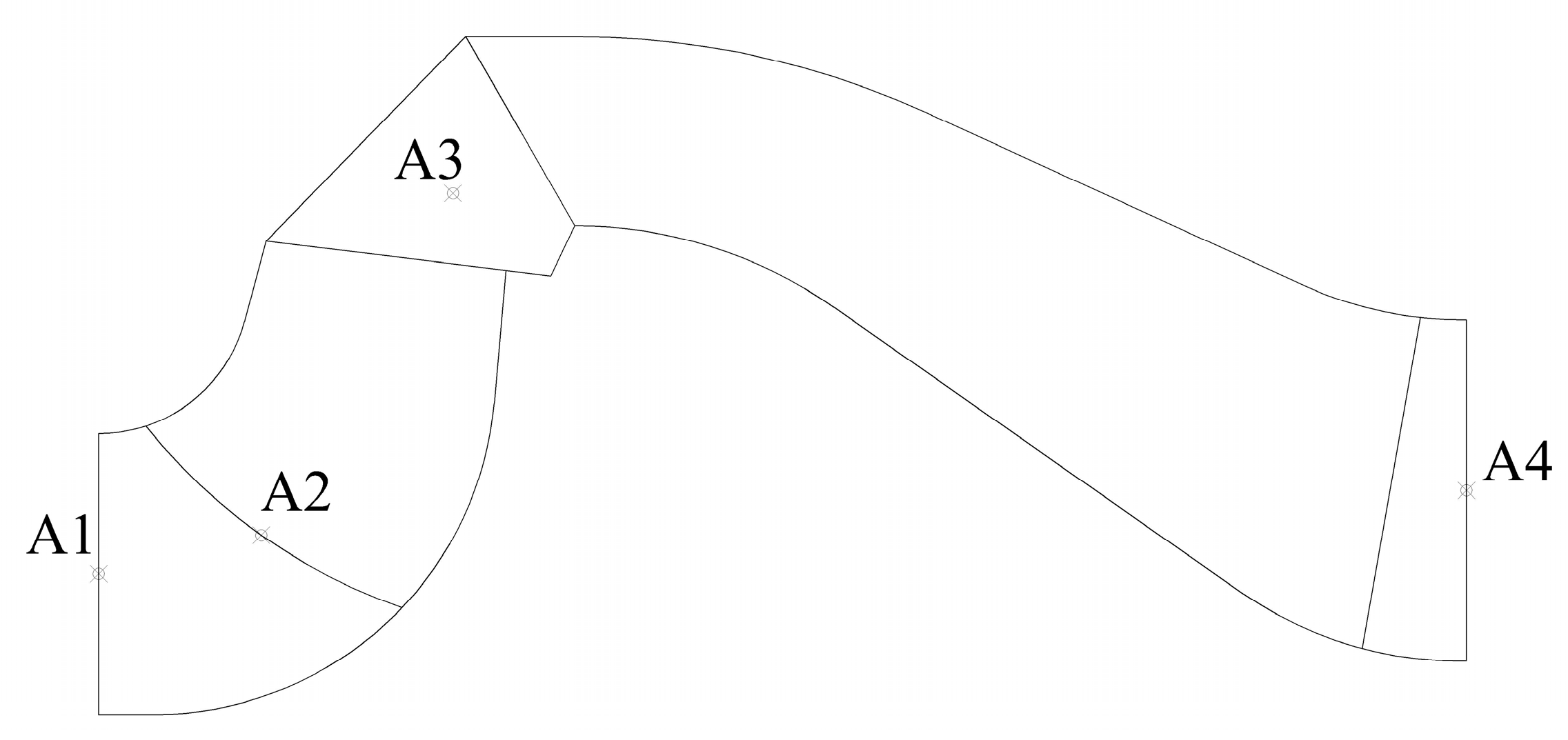
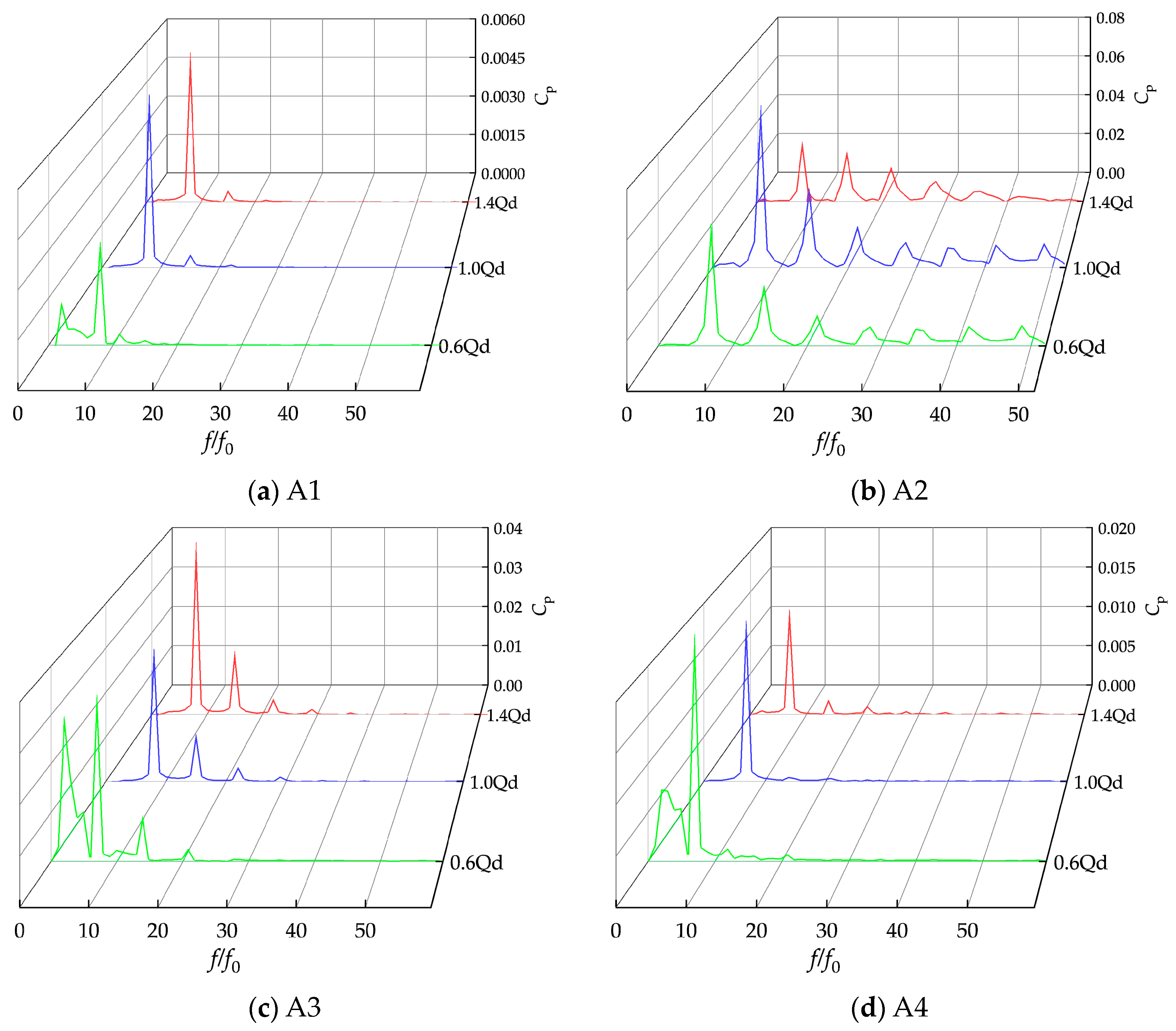
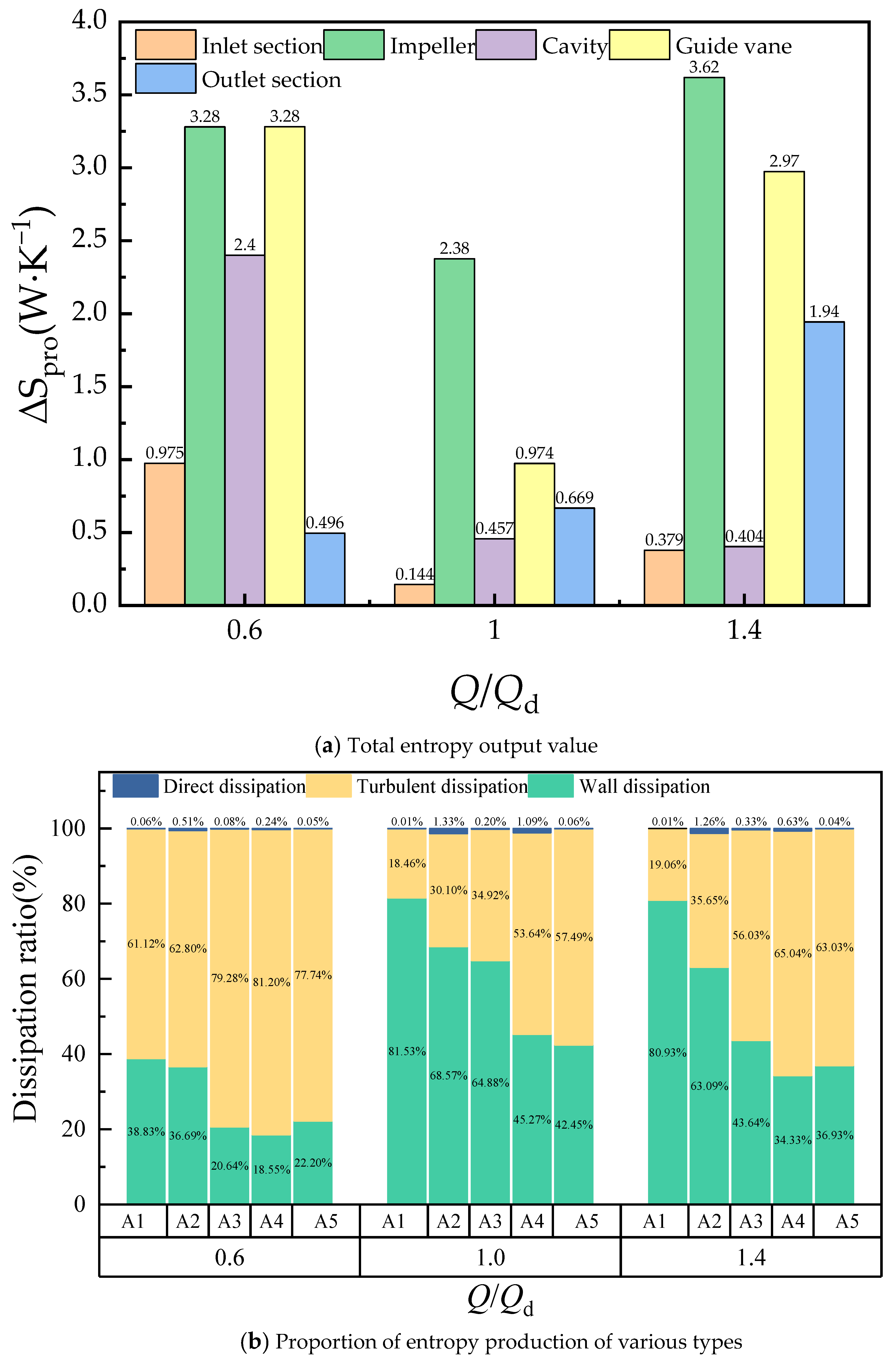
- Analyzing the transient flow characteristics of the optimized model: At rated flow rates, the fluid flow within the pump remains stable. At large flow rates, flow separation is prone to occur at the leading and trailing edges of the blades. At small flow rates, the fluid flow within the pump becomes more turbulent. The pressure fluctuations within the impeller are primarily caused by the interaction between the blades and the fluid. For the cavity and guide vane, pressure fluctuations predominantly result from the rotor–stator interference. These pressure fluctuations exhibit strong periodicity, with their dominant frequencies situated around the blade frequency. At small flow rates, the turbulence generated by the unstable flow inside the pump also becomes one of the main causes of pressure fluctuations. At large flow rates, fluid separation occurs at the leading and trailing edges of the blades, resulting in variations in pressure pulsation amplitude. In the centrifugal pump with guide vanes, the turbulent and wall dissipations contribute higher values compared with the direct dissipation. At the rated flow rates, the entropy generation is concentrated in the impeller. At large flow rates, the increase in fluid velocity leads to an augmentation in wall friction dissipation and intensifies the flow separation, resulting in an escalation of turbulent dissipation at the leading and trailing edges of the blades. At small flow rates, the turbulence generated by the unstable fluid flow becomes the primary source of turbulent dissipation. At this point, the entropy production value of the guide vane centrifugal pump is the highest.
Author Contributions
Funding
Institutional Review Board Statement
Informed Consent Statement
Data Availability Statement
Conflicts of Interest
Abbreviations
| Qd | Design flow rate, m3/h |
| Hd | Design head, m |
| n | Design speed, r/min |
| ns | Specific speed |
| H | Head, m |
| η | Efficiency, % |
| Dj | Impeller inlet diameter, mm |
| D2 | Impeller outlet diameter, mm |
| b2 | Impeller outlet width, mm |
| Dh | Impeller hub diameter, mm |
| β1 | Impeller blade inlet angle, ° |
| β2 | Impeller blade outlet angle, ° |
| φ1 | Impeller blade wrap angle, ° |
| b3 | Guide vane inlet width, mm |
| φ2 | Guide vane wrap angle, ° |
| α3 | Guide vane inlet setting angle, ° |
| α4 | Guide vane outlet setting angle, ° |
| L | Guide vane axial length, mm |
| ∆z | Axial distance between impeller and guide vane, mm |
| ∆r | Radial distance between impeller and guide vane, mm |
| Z | Number of impeller blades |
| S2 | Variance |
| R² | Coefficient of determination |
| Adjusted coefficient of determination | |
| Predictive coefficient of determination | |
| Ha | Head coefficient, m |
| Pinlet | Average pressure at the inlet surface, Pa |
| Pave | Average pressure at any cross section of the guide vane centrifugal pump, Pa. |
| Cp | Nondimensional pressure fluctuation coefficient |
| p | Static pressure at the monitoring point, Pa. |
| Time-averaged pressure at the monitoring point during the computation period, Pa. | |
| ρ | Fluid density, kg/m³ |
| u2 | Circumferential velocity at the impeller outlet, m/s |
| f0 | Impeller rotational frequency |
| Direct dissipation entropy generation rate, kg·m−1·s−3·K−1 | |
| Turbulent dissipation entropy production rate, kg· m−1·s−3·K−1 | |
| Wall dissipation entropy generation rate, kg·s−3·K−1 | |
| Local total entropy generation rate, kg·m−1·s−3·K−1 | |
| Total entropy production, W·K−1 | |
| μ | Dynamic viscosity of the fluid, kg·m−1·s−1 |
| u, v, w | Components of velocity in the Cartesian coordinate system’s x, y, and z directions, respectively, m/s |
| T | Temperature, K |
| ω | Turbulent eddy frequency, s−1 |
| k | Turbulent kinetic energy, m2/s2 |
| Wall shear stress, Pa | |
| Velocity near the wall, m/s | |
| Acronyms | |
| CFD | Computational fluid dynamics |
| DOE | Design of experiment |
| RSM | Response surface method |
| SSM | Surrogate model method |
References
- Shi, W.; Zhou, L.; Lu, W.; Xu, L.; Li, W. Numerical Simulation and Experimental Study of Different Stages Deep-Well Centrifugal Pump. J. Comput. Theor. Nanosci. 2013, 10, 2897–2901. [Google Scholar] [CrossRef]
- Zhou, L.; Shi, W.; Lu, W.; Hu, B.; Wu, S. Numerical Investigations and Performance Experiments of a Deep-Well Centrifugal Pump With Different Diffusers. J. Fluids Eng. 2012, 134, 071102. [Google Scholar] [CrossRef]
- Xuran, G.; Puyu, C.; Yang, W.; Rui, Z.; Yefu, W. Linear control design and internal flow analysis of diffuser trailing edge based on CFD. J. Drain. Irrig. Mach. Eng. 2021, 39, 1210–1217. [Google Scholar]
- Zailun, L.; Sanzhen, W.; Jingmin, Z.; Jinxuan, W. Optimal design of geometric parameters of diffuser inlet under optimal working conditions. J. Drain. Irrig. Mach. Eng. 2021, 39, 973–980. [Google Scholar]
- Kim, S.; Kim, Y.-I.; Kim, J.-H.; Choi, Y.-S. Design optimization for mixed-flow pump impeller by improved suction performance and efficiency with variables of specific speeds. J. Mech. Sci. Technol. 2020, 34, 2377–2389. [Google Scholar] [CrossRef]
- Heo, M.-W.; Kim, K.-Y.; Kim, J.-H.; Choi, Y.S. High-efficiency design of a mixed-flow pump using a surrogate model. J. Mech. Sci. Technol. 2016, 30, 541–547. [Google Scholar] [CrossRef]
- Safikhani, H.; Khalkhali, A.; Farajpoor, M. Pareto based multi-objective optimization of centrifugal pumps using CFD, neural networks and genetic algorithms. Eng. Appl. Comput. Fluid Mech. 2011, 5, 37–48. [Google Scholar] [CrossRef]
- Alawadhi, K.; Alzuwayer, B.; Mohammad, T.A.; Buhemdi, M.H. Design and Optimization of a Centrifugal Pump for Slurry Transport Using the Response Surface Method. Machines 2021, 9, 60. [Google Scholar] [CrossRef]
- Wang, W.J.; Yuan, S.Q.; Pei, J.; Zhang, J.F. Optimization of the diffuser in a centrifugal pump by combining response surface method with multi-island genetic algorithm. Proc. Inst. Mech. Eng. Part E J. Process Mech. Eng. 2016, 231, 191–201. [Google Scholar] [CrossRef]
- Kim, J.-H.; Lee, H.-C.; Kim, J.-H.; Yoon, J.-Y.; Choi, Y.-S. Design techniques to improve the performance of a centrifugal pump using CFD. J. Mech. Sci. Technol. 2015, 29, 215–225. [Google Scholar] [CrossRef]
- Nataraj, M.; Singh, R.R. Analyzing pump impeller for performance evaluation using RSM and CFD. Desalination Water Treat. 2014, 52, 6822–6831. [Google Scholar] [CrossRef]
- Thakkar, S.; Vala, H.; Patel, V.K.; Patel, R. Performance improvement of the sanitary centrifugal pump through an integrated approach based on response surface methodology, multi-objective optimization and CFD. J. Braz. Soc. Mech. Sci. Eng. 2021, 43, 24. [Google Scholar] [CrossRef]
- Wu, C.; Yang, J.; Yang, S.; Wu, P.; Huang, B.; Wu, D. A Review of Fluid-Induced Excitations in Centrifugal Pumps. Mathematics 2023, 11, 1026. [Google Scholar] [CrossRef]
- Posa, A.; Lippolis, A. Effect of working conditions and diffuser setting angle on pressure fluctuations within a centrifugal pump. Int. J. Heat Fluid Flow 2019, 75, 44–60. [Google Scholar] [CrossRef]
- Shibata, A.; Hiramatsu, H.; Komaki, S.; Miyagawa, K.; Maeda, M.; Kamei, S.; Hazama, R.; Sano, T.; Iino, M. Study of flow instability in off design operation of a multistage centrifugal pump. J. Mech. Sci. Technol. 2016, 30, 493–498. [Google Scholar] [CrossRef]
- Qi, H.; Li, W.; Ji, L.; Liu, M.; Song, R.; Pan, Y.; Yang, Y. Performance optimization of centrifugal pump based on particle swarm optimization and entropy generation theory. Front. Energy Res. 2023, 10, 1094717. [Google Scholar] [CrossRef]
- Osman, M.K.; Wang, W.; Yuan, J.; Zhao, J.; Wang, Y.; Liu, J. Flow loss analysis of a two-stage axially split centrifugal pump with double inlet under different channel designs. Proc. Inst. Mech. Eng. Part C J. Mech. Eng. Sci. 2019, 233, 5316–5328. [Google Scholar] [CrossRef]
- Huang, P.; Appiah, D.; Chen, K.; Zhang, F.; Cao, P.; Hong, Q. Energy dissipation mechanism of a centrifugal pump with entropy generation theory. Aip Adv. 2021, 11, 045208. [Google Scholar] [CrossRef]
- Böhle, M.; Fleder, A.; Mohr, M. Study of the losses in fluid machinery with the help of entropy. In Proceedings of the 16th International Symposium on Transport Phenomena and Dynamics of Rotating Machinery, Honolulu, HI, USA, 10–15 April 2016. [Google Scholar]
- Melzer, S.; Pesch, A.; Schepeler, S.; Kalkkuhl, T.; Skoda, R. Three-Dimensional Simulation of Highly Unsteady and Isothermal Flow in Centrifugal Pumps for the Local Loss Analysis Including a Wall Function for Entropy Production. J. Fluids Eng. 2020, 142, 111209. [Google Scholar] [CrossRef]
- Yang, B.; Li, B.; Chen, H.; Liu, Z. Entropy production analysis for the clocking effect between inducer and impeller in a high-speed centrifugal pump. Proc. Inst. Mech. Eng. Part C J. Mech. Eng. Sci. 2019, 233, 5302–5315. [Google Scholar] [CrossRef]
- Ning, Z.; Kun, Z.F.; Kai, L.X.; Xian, J.J. Distribution and evolution characteristics of complex flow field in a low specific speed centrifugal pump. Fluid Mach. 2023, 51, 27–32. [Google Scholar]
- Box, G.E.P.; Wilson, K.B. On the Experimental Attainment of Optimum Conditions. In Breakthroughs in Statistics: Methodology and Distribution; Kotz, S., Johnson, N.L., Eds.; Springer: New York, NY, USA, 1992; pp. 270–310. [Google Scholar] [CrossRef]
- Siddiqi, A.; Shabbir, M.S.; Khalid, F. A short comment on the use of R_adj^2 in social science. Rev. San Gregor. 2019, 1, 25–31. [Google Scholar] [CrossRef]
- Walsh, E.J.; Mc Eligot, D.M.; Brandt, L.; Schlatter, P. Entropy generation in a boundary layer transitioning under the influence of freestream turbulence. J. Fluids Eng. 2011, 133, 061203. [Google Scholar] [CrossRef]
- Zhou, L.; Hang, J.; Bai, L.; Krzemianowski, Z.; El-Emam, M.A.; Yasser, E.; Agarwal, R. Application of entropy production theory for energy losses and other investigation in pumps and turbines: A review. Appl. Energy 2022, 318, 119211. [Google Scholar] [CrossRef]

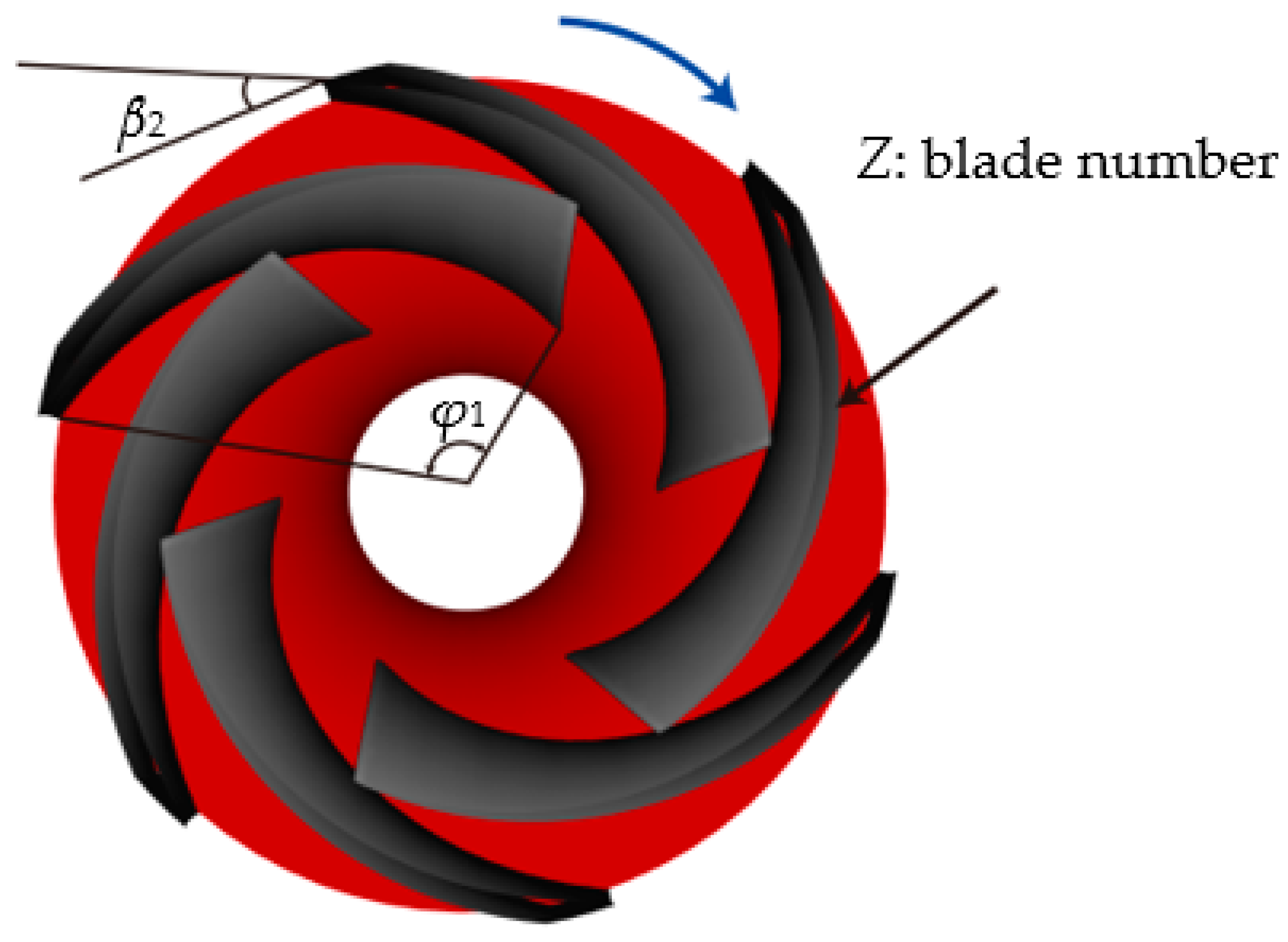







| Impeller | Guide Vane | ||||
|---|---|---|---|---|---|
| Inlet diameter | Dj (mm) | 120 | Inlet width | b3 (mm) | 28.83 |
| Outlet diameter | D2 (mm) | 167 | Guide vane wrap angle | φ2 (°) | 105 |
| Outlet width | b2 (mm) | 32 | Inlet setting angle | α3 (°) | 16.5 |
| Hub diameter | Dh (mm) | 46 | Outlet setting angle | α4 (°) | 90 |
| Blade inlet angle | β1 (°) | 22.3 | Axial length | L (mm) | 136.6 |
| Blade outlet angle | β2 (°) | 25 | Axial distance from the impeller | ∆z (mm) | 17.783 |
| Blade wrap angle | φ1 (°) | 105 | Radial distance from the impeller | ∆r (mm) | 16.5 |
| Factor | Unit | Coding and Levels | ||
|---|---|---|---|---|
| −1 | 0 | 1 | ||
| A | / | 5 | 6 | 7 |
| B | ° | 100 | 105 | 110 |
| C | ° | 22 | 25 | 28 |
| D | mm | 10 | 16.5 | 23 |
| E | mm | 10.783 | 17.783 | 24.783 |
| NO. | Z | φ1/ ° | β2/° | ∆z/mm | ∆r /mm | H/mm | η/% |
|---|---|---|---|---|---|---|---|
| 1 | 5 | 100 | 25 | 16.5 | 17.783 | 26.0428 | 81.58 |
| 2 | 7 | 105 | 28 | 16.5 | 17.783 | 28.5062 | 79.23 |
| 3 | 6 | 105 | 25 | 10 | 24.783 | 27.2011 | 78.15 |
| 4 | 6 | 105 | 25 | 23 | 24.783 | 27.8336 | 82.59 |
| 5 | 7 | 105 | 25 | 23 | 17.783 | 28.6453 | 82.2 |
| 6 | 6 | 100 | 25 | 16.5 | 10.783 | 28.2165 | 82.51 |
| 7 | 6 | 105 | 22 | 23 | 17.783 | 27.6343 | 84.1 |
| 8 | 6 | 105 | 22 | 16.5 | 24.783 | 26.9736 | 81.22 |
| 9 | 6 | 105 | 25 | 10 | 10.783 | 26.2491 | 78.03 |
| 10 | 6 | 105 | 25 | 16.5 | 17.783 | 26.8446 | 78.65 |
| 11 | 6 | 105 | 25 | 16.5 | 17.783 | 27.1076 | 80.55 |
| 12 | 7 | 110 | 25 | 16.5 | 17.783 | 27.2184 | 80.79 |
| 13 | 6 | 110 | 25 | 23 | 17.783 | 27.3596 | 84.44 |
| 14 | 6 | 105 | 25 | 16.5 | 17.783 | 26.7649 | 78.42 |
| 15 | 5 | 105 | 25 | 23 | 17.783 | 25.5676 | 83.45 |
| 16 | 7 | 100 | 25 | 16.5 | 17.783 | 28.7661 | 79.72 |
| 17 | 6 | 100 | 25 | 10 | 17.783 | 27.1373 | 78.42 |
| 18 | 5 | 105 | 25 | 10 | 17.783 | 24.9897 | 78.85 |
| 19 | 5 | 105 | 28 | 16.5 | 17.783 | 25.8279 | 81.15 |
| 20 | 6 | 100 | 25 | 16.5 | 24.783 | 28.0107 | 80.38 |
| 21 | 7 | 105 | 25 | 10 | 17.783 | 27.602 | 78.35 |
| 22 | 5 | 105 | 25 | 16.5 | 10.783 | 25.4507 | 82.36 |
| 23 | 6 | 105 | 25 | 16.5 | 17.783 | 26.9445 | 81.16 |
| 24 | 6 | 110 | 28 | 16.5 | 17.783 | 26.911 | 80.55 |
| 25 | 6 | 105 | 25 | 16.5 | 17.783 | 27.1163 | 81.12 |
| 26 | 6 | 105 | 28 | 10 | 17.783 | 27.2237 | 77.57 |
| 27 | 6 | 110 | 22 | 16.5 | 17.783 | 26.4126 | 83.4 |
| 28 | 6 | 110 | 25 | 16.5 | 10.783 | 26.8401 | 82.38 |
| 29 | 6 | 105 | 28 | 16.5 | 10.783 | 27.9743 | 81.38 |
| 30 | 6 | 110 | 25 | 16.5 | 24.783 | 26.9129 | 80.93 |
| 31 | 6 | 105 | 25 | 23 | 10.783 | 27.9071 | 83.42 |
| 32 | 6 | 105 | 28 | 23 | 17.783 | 28.3229 | 82.82 |
| 33 | 5 | 105 | 25 | 16.5 | 24.783 | 25.7726 | 81.28 |
| 34 | 6 | 105 | 28 | 16.5 | 24.783 | 28.1058 | 79.91 |
| 35 | 5 | 110 | 25 | 16.5 | 17.783 | 24.6338 | 82.29 |
| 36 | 6 | 100 | 25 | 23 | 17.783 | 28.5292 | 83.33 |
| 37 | 6 | 100 | 22 | 16.5 | 17.783 | 27.15 | 81.59 |
| 38 | 7 | 105 | 25 | 16.5 | 24.783 | 28.6561 | 79.87 |
| 39 | 6 | 105 | 22 | 16.5 | 10.783 | 27.3353 | 83.24 |
| 40 | 6 | 110 | 25 | 10 | 17.783 | 26.0842 | 78.64 |
| 41 | 7 | 105 | 22 | 16.5 | 17.783 | 27.6087 | 81.1 |
| 42 | 5 | 105 | 22 | 16.5 | 17.783 | 25.0074 | 83.15 |
| 43 | 6 | 105 | 22 | 10 | 17.783 | 26.122 | 79.13 |
| 44 | 7 | 105 | 25 | 16.5 | 10.783 | 28.0735 | 82.75 |
| 45 | 6 | 105 | 25 | 16.5 | 17.783 | 27.1399 | 81.01 |
| 46 | 6 | 100 | 28 | 16.5 | 17.783 | 28.2545 | 80.13 |
| X1 | 26.986 | X8 | −0.0346 | X15 | 0.069 | Y1 | 80.152 | Y8 | 0.09 | Y15 | 0.17 |
| X2 | 1.361 | X9 | 0.116 | X16 | −0.256 | Y2 | −0.631 | Y9 | −0.188 | Y16 | −0.238 |
| X3 | 0.43 | X10 | 0.065 | X17 | −0.401 | Y3 | 0.887 | Y10 | −0.45 | Y17 | 0.468 |
| X4 | −0.608 | X11 | −0.151 | X18 | 0.182 | Y4 | 0.36 | Y11 | −0.347 | Y18 | 0.597 |
| X5 | 0.574 | X12 | −0.103 | X19 | 0.107 | Y5 | 2.451 | Y12 | 0.07 | Y19 | 0.714 |
| X6 | 0.088 | X13 | 0.123 | X20 | 0.102 | Y6 | −0.734 | Y13 | 0.137 | Y20 | 0.082 |
| X7 | 0.019 | X14 | −0.029 | X21 | 0.361 | Y7 | 0.0325 | Y14 | 0.222 | Y21 | 0.658 |
| Response Variable | Sum of Squares | Degree of Freedom | Mean Square | p-Value | |||
|---|---|---|---|---|---|---|---|
| Head | 48.47 | 20 | 2.42 | <0.0001 | 0.9810 | 0.9658 | 0.9306 |
| Efficiency | 136.21 | 20 | 6.81 | <0.0001 | 0.9066 | 0.8318 | 0.7644 |
| Single Factor | Z | β2 | φ1 | ∆r | ∆z |
| p-value | <0.0001 | <0.0001 | <0.0001 | <0.0001 | 0.0788 |
| Two-Factor Interaction | Zβ2 | Zφ1 | Z∆r | Z∆z | β2φ1 |
| p-value | 0.8440 | 0.7233 | 0.2408 | 0.5071 | 0.1302 |
| Two-Factor Interaction | β2∆r | β2∆z | φ1∆r | φ1∆z | ∆r∆z |
| p-value | 0.2964 | 0.2146 | 0.7661 | 0.4786 | 0.0138 |
| Single-Factor Quadratic | Z2 | β22 | φ12 | ∆r2 | ∆z2 |
| p-value | <0.0001 | 0.0102 | 0.1124 | 0.1325 | <0.0001 |
| Single Factor | Z | β2 | φ1 | ∆r | ∆z |
| p-value | 0.0024 | <0.0001 | 0.0661 | <0.0001 | 0.0006 |
| Two-Factor Interaction | Zβ2 | Zφ1 | Z∆r | Z∆z | β2φ1 |
| p-value | 0.9316 | 0.8121 | 0.6211 | 0.2410 | 0.3625 |
| Two-Factor Interaction | β2∆r | β2∆z | φ1∆r | φ1∆z | ∆r∆z |
| p-value | 0.8533 | 0.7167 | 0.5579 | 0.6539 | 0.5319 |
| Single-Factor Quadratic | Z2 | β22 | φ12 | ∆r2 | ∆z2 |
| p-value | 0.0770 | 0.0267 | 0.0093 | 0.7489 | 0.0156 |
| Model | Z | β2 | φ1 | ∆r | ∆z | H (m) | η (%) | ||
|---|---|---|---|---|---|---|---|---|---|
| Predicted Values | Computed Values | Predicted Values | Computed Values | ||||||
| Optimized model | 7 | 23.8 | 100.7 | 22.814 | 13.838 | 29.443 | 29.6921 | 83.664 | 83.43 |
| Original model | 6 | 25 | 105 | 16.5 | 17.783 | 26.986 | 27.1076 | 80.152 | 80.55 |
Disclaimer/Publisher’s Note: The statements, opinions and data contained in all publications are solely those of the individual author(s) and contributor(s) and not of MDPI and/or the editor(s). MDPI and/or the editor(s) disclaim responsibility for any injury to people or property resulting from any ideas, methods, instructions or products referred to in the content. |
© 2023 by the authors. Licensee MDPI, Basel, Switzerland. This article is an open access article distributed under the terms and conditions of the Creative Commons Attribution (CC BY) license (https://creativecommons.org/licenses/by/4.0/).
Share and Cite
Cao, W.; Wang, H.; Yang, X.; Leng, X. Optimization of Guide Vane Centrifugal Pumps Based on Response Surface Methodology and Study of Internal Flow Characteristics. J. Mar. Sci. Eng. 2023, 11, 1917. https://doi.org/10.3390/jmse11101917
Cao W, Wang H, Yang X, Leng X. Optimization of Guide Vane Centrifugal Pumps Based on Response Surface Methodology and Study of Internal Flow Characteristics. Journal of Marine Science and Engineering. 2023; 11(10):1917. https://doi.org/10.3390/jmse11101917
Chicago/Turabian StyleCao, Weidong, He Wang, Xinyu Yang, and Xinyi Leng. 2023. "Optimization of Guide Vane Centrifugal Pumps Based on Response Surface Methodology and Study of Internal Flow Characteristics" Journal of Marine Science and Engineering 11, no. 10: 1917. https://doi.org/10.3390/jmse11101917
APA StyleCao, W., Wang, H., Yang, X., & Leng, X. (2023). Optimization of Guide Vane Centrifugal Pumps Based on Response Surface Methodology and Study of Internal Flow Characteristics. Journal of Marine Science and Engineering, 11(10), 1917. https://doi.org/10.3390/jmse11101917


