
Experimental Challenges and Modelling Approaches of Floating Wind Turbines


Abstract
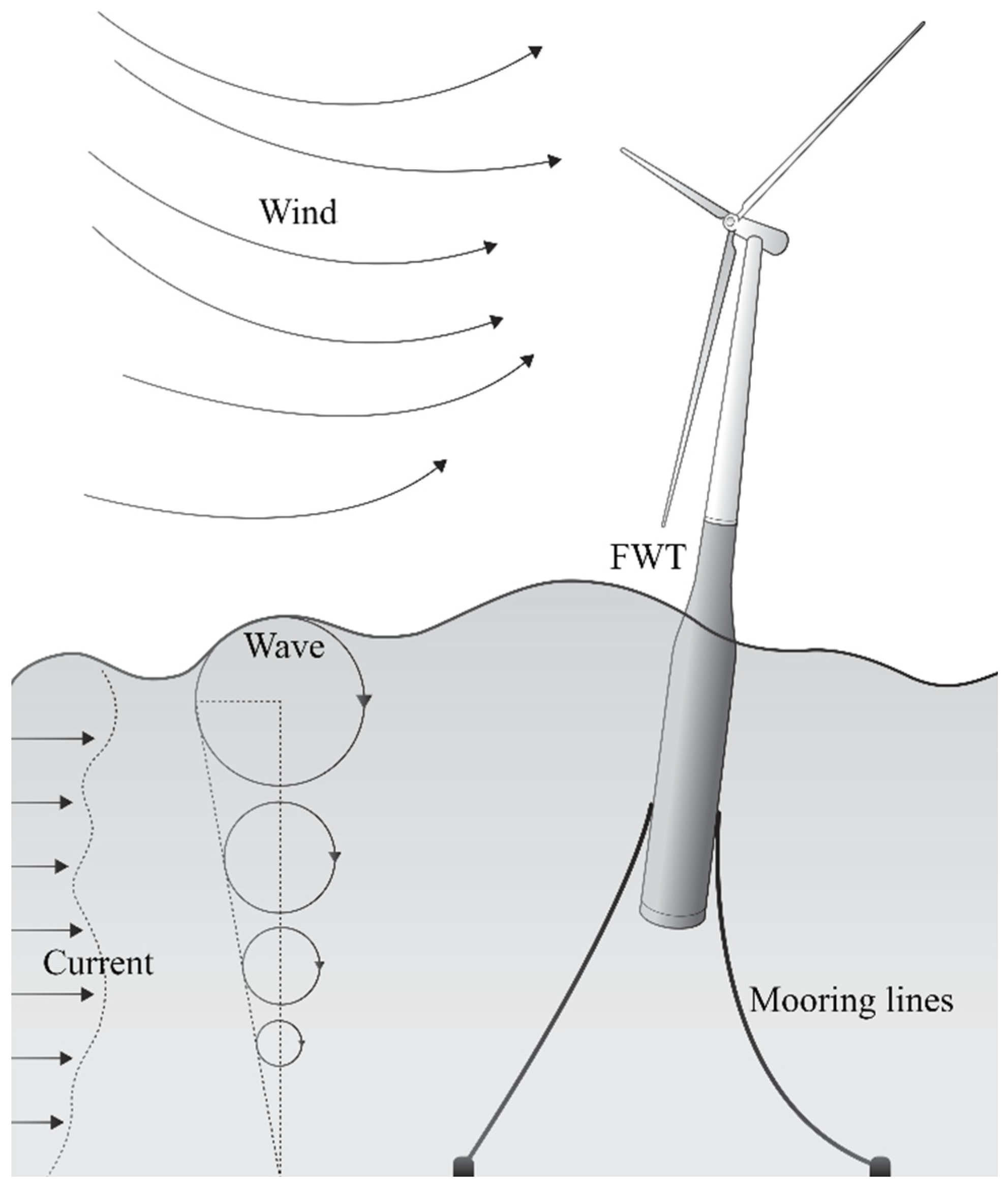
:1. Introduction
2. Froude and Reynolds Similitude
3. Significance of Aerodynamic Phenomena
3.1. Aerodynamic Loads
3.2. Inertial Loads
3.3. Loads Frequency Bandwidth
- The wave frequency (WF) range exciting the platform motions.
- The 1P and NP rotor frequencies range corresponding to the frequency of one full rotation of the rotor and the frequency at which one blade among N blades passes in front of the tower. NP would be referred to as the 3P frequency for a three-blade WT.
- The first fore–aft and side–side tower bending mode (Twr 1st).
- The high frequency (HF) range, including the blade modes (flapwise and edgewise).
4. Early-Stage Methods
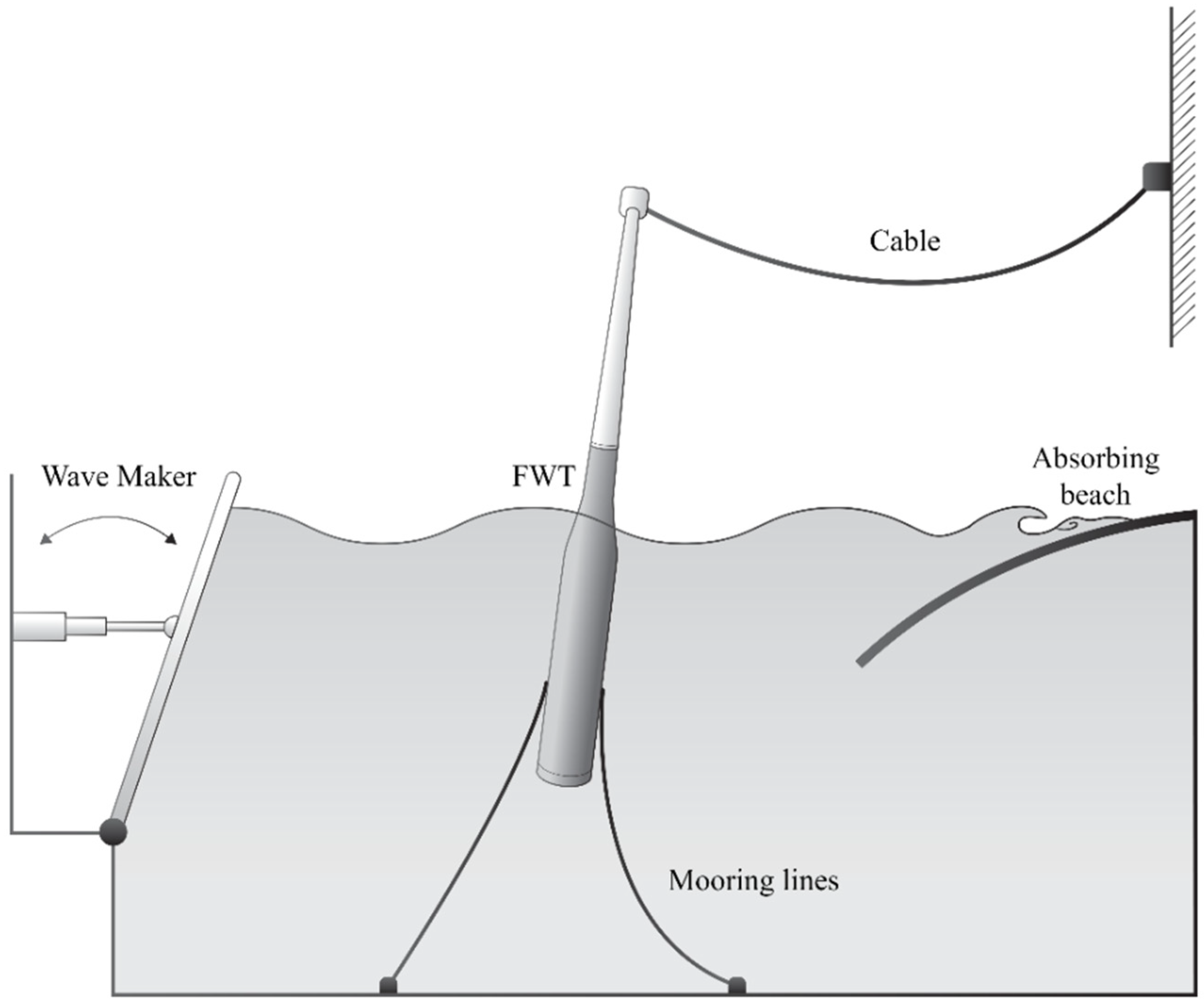
4.1. Static Cables
4.2. Porous Disc
5. Physical Rotor
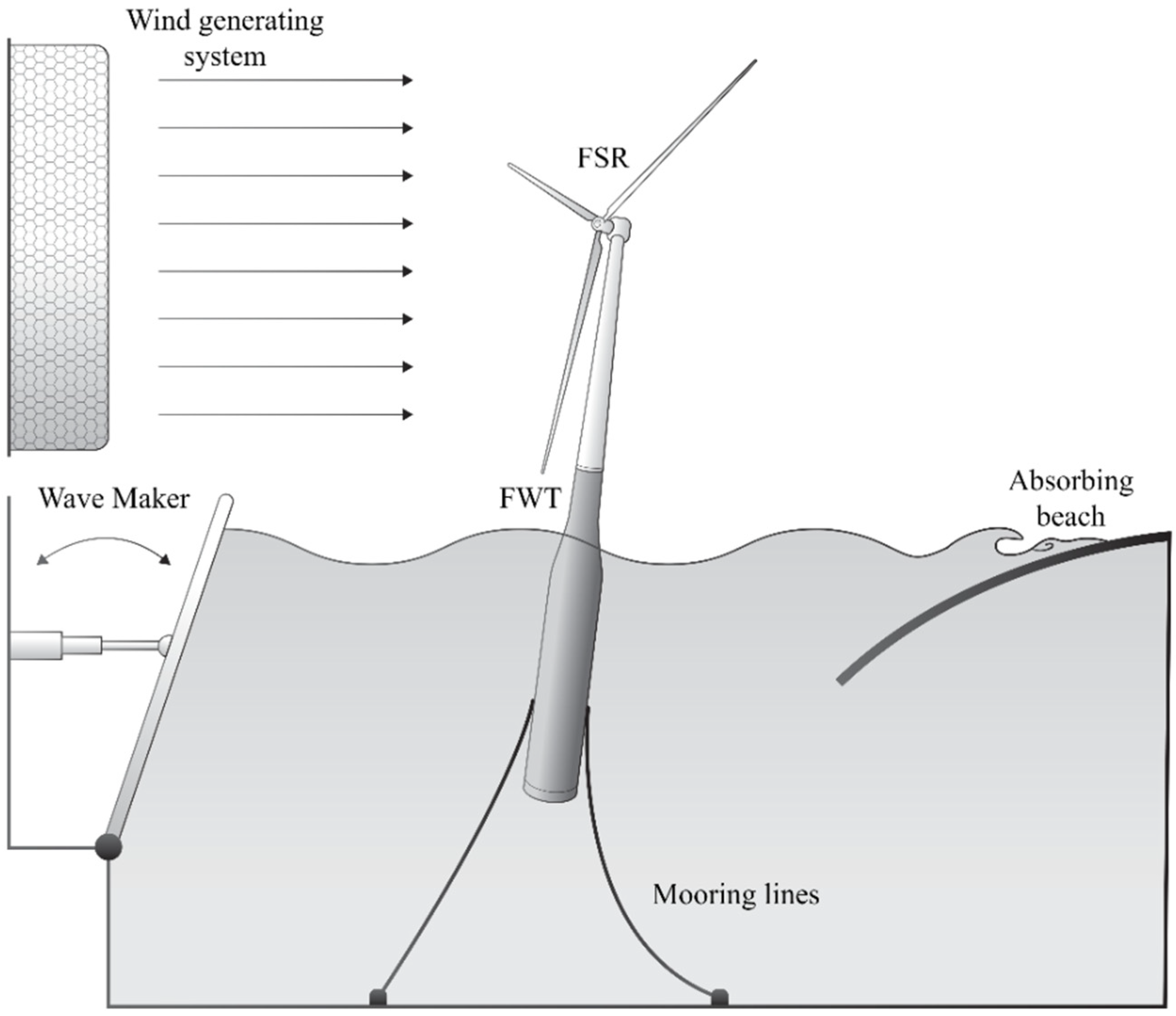
5.1. Froude-Scaled Rotors
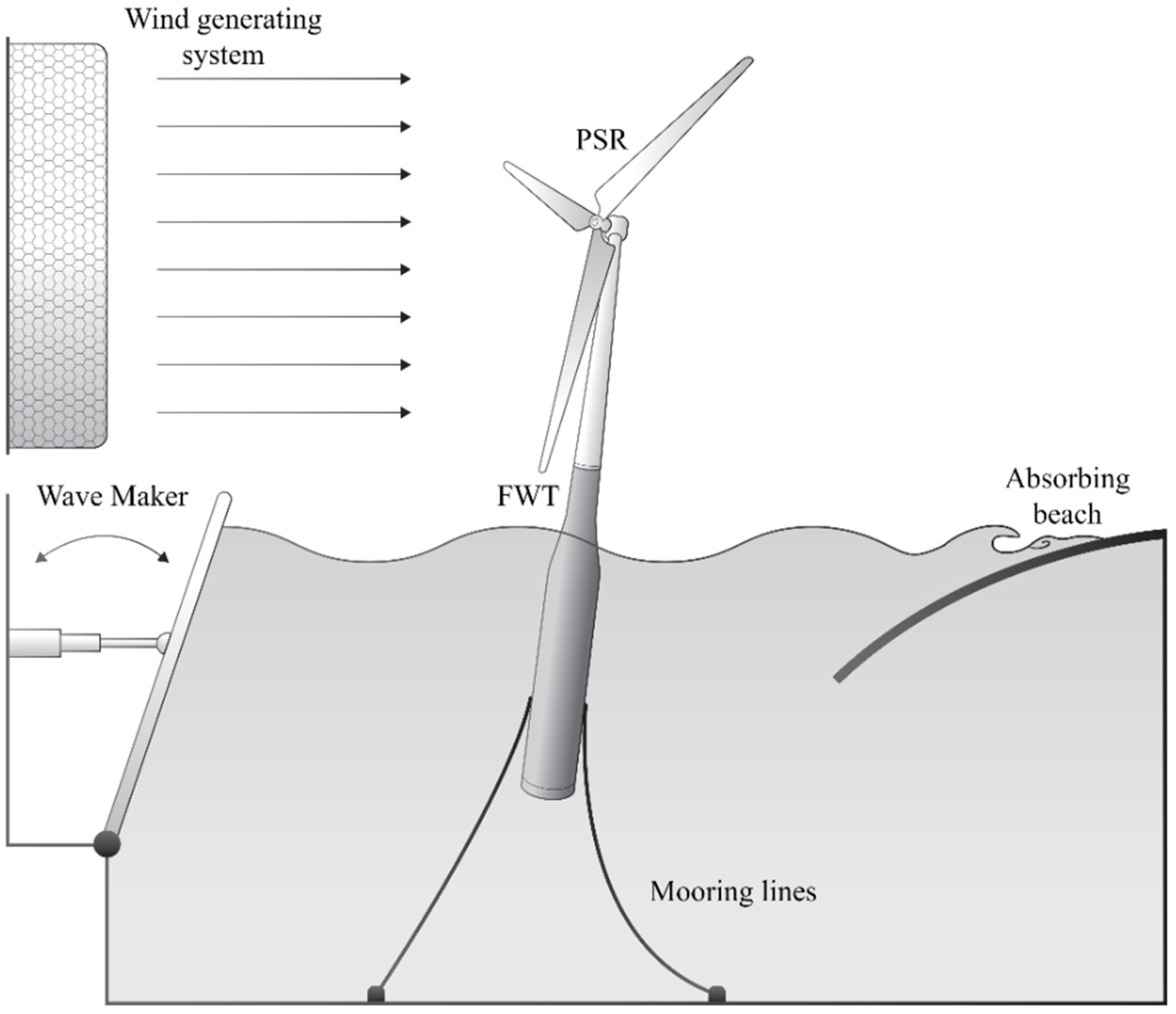
5.2. Performance-Scaled Rotor
6. Hybrid Testing
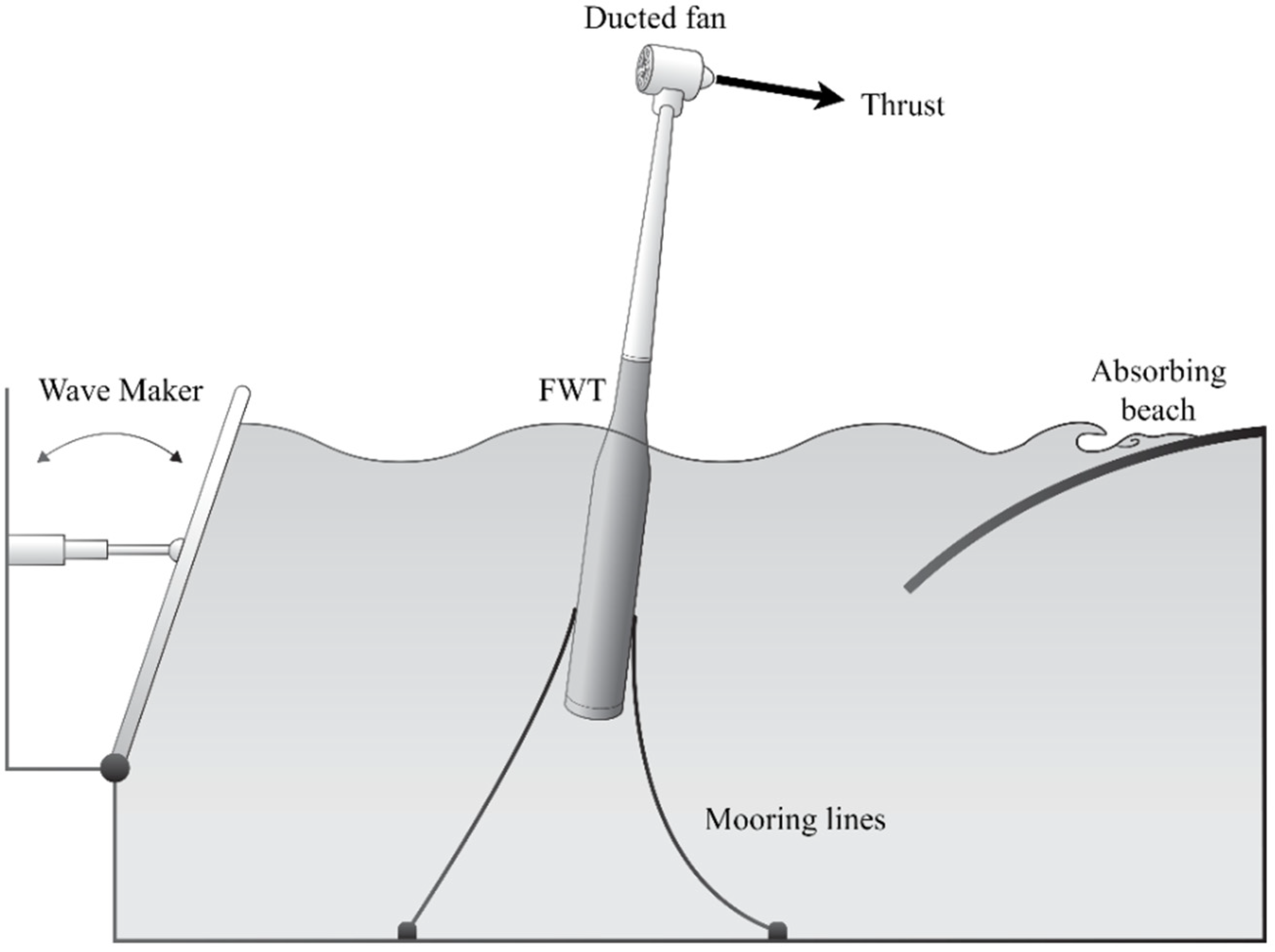
6.1. Propeller Actuators
6.2. Cable Winch Actuators
6.3. Wind Tunnel Tests
7. Methods Comparison and Applicability
7.1. Hybrid vs. Physical Rotor Testing
7.2. Actuators’ Suitability in Hybrid Testing
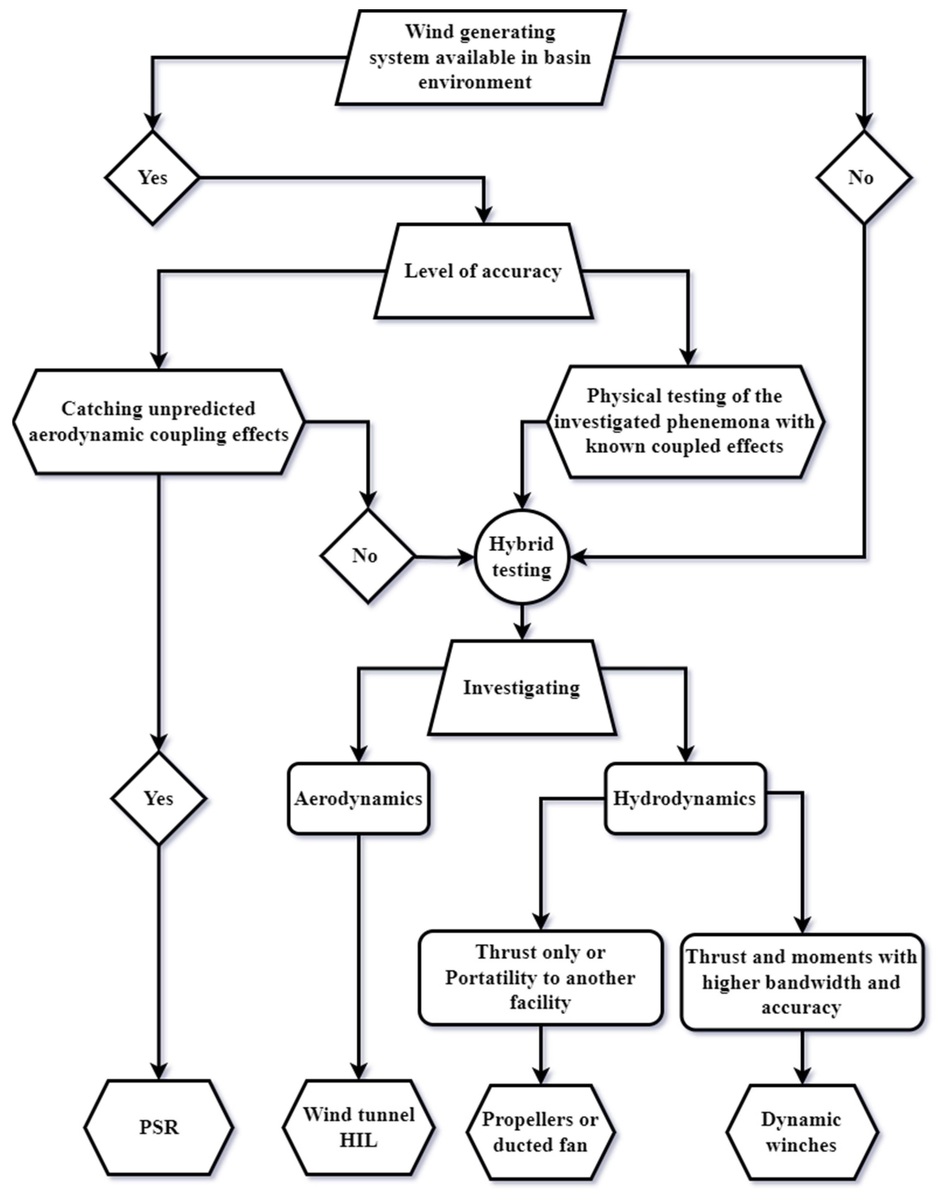
7.3. Method Selection Roadmap
8. Conclusions
Author Contributions
Funding
Institutional Review Board Statement
Informed Consent Statement
Data Availability Statement
Conflicts of Interest
References
- Díaz, H.; Guedes Soares, C. Review of the Current Status, Technology and Future Trends of Offshore Wind Farms. Ocean. Eng. 2020, 209, 107381. [Google Scholar] [CrossRef]
- Díaz, H.; Serna, J.; Nieto, J.; Guedes Soares, C. Market Needs, Opportunities and Barriers for the Floating Wind Industry. J. Mar. Sci. Eng. 2022, 10, 934. [Google Scholar] [CrossRef]
- Wind Europe. Wind Energy in Europe—Statistics and the Outlook for 2021–2025; WindEurope: Brussels, Belgium, 2021; p. 36. [Google Scholar]
- Bagbanci, H.; Karmakar, D.; Guedes Soares, C. Review of Offshore Floating Wind Turbines Concepts. In Maritime Engineering and Technology; Guedes Soares, C., Garbatov, Y., Sutulo, S., Santos, T.A., Eds.; Taylor & Francis Group: London, UK, 2012; pp. 553–562. [Google Scholar] [CrossRef]
- Uzunoglu, E.; Guedes Soares, C. Hydrodynamic Design of a Free-Float Capable Tension Leg Platform for a 10 MW Wind Turbine. Ocean. Eng. 2020, 197, 106888. [Google Scholar] [CrossRef]
- Damiani, R.; Dykes, K.; Scott, G. A Comparison Study of Offshore Wind Support Structures with Monopiles and Jackets for U.S. Waters. J. Phys. Conf. Ser. 2016, 753, 092003. [Google Scholar] [CrossRef]
- Castro-Santos, L.; Silva, D.; Bento, A.R.; Salvação, N.; Guedes Soares, C. Economic Feasibility of Floating Offshore Wind Farms in Portugal. Ocean. Eng. 2020, 207, 107393. [Google Scholar] [CrossRef]
- Castro-Santos, L.; Bento, A.R.; Silva, D.; Salvação, N.; Guedes Soares, C. Economic Feasibility of Floating Offshore Wind Farms in the North of Spain. J. Mar. Sci. Eng. 2020, 8, 58. [Google Scholar] [CrossRef]
- Uzunoglu, E.; Karmakar, D.; Guedes Soares, C. Floating Offshore Wind Platforms. In Floating Offshore Wind Farms; Castro-Santos, L., Diaz-Casas, V., Eds.; Green Energy and Technology; Springer International Publishing: Cham, Switzerland, 2016; pp. 53–76. [Google Scholar] [CrossRef]
- Collu, M.; Borg, M. Design of Floating Offshore Wind Turbines. In Offshore Wind Farms; Elsevier: Amsterdam, The Netherlands, 2016; pp. 359–385. ISBN 978-0-08-100779-2. [Google Scholar]
- Skaare, B.; Nielsen, F.G.; Hanson, T.D.; Yttervik, R.; Havmøller, O.; Rekdal, A. Analysis of Measurements and Simulations from the Hywind Demo Floating Wind Turbine. Wind Energy 2015, 18, 1105–1122. [Google Scholar] [CrossRef]
- Roddier, D.; Cermelli, C.; Aubault, A.; Weinstein, A. WindFloat: A Floating Foundation for Offshore Wind Turbines. J. Renew. Sustain. Energy 2010, 2, 033104. [Google Scholar] [CrossRef]
- Reynaud, M.; Le Bouhris, E.; Soulard, T.; Yves, P. Rapport de Suivi Environnemental de L’éolienne Flottante FLOATGEN, Site D’essais SEM-REV; Zenodo: Genève, Switzerland, 2021. [Google Scholar] [CrossRef]
- Galván, J.; Sánchez-Lara, M.J.; Mendikoa, I.; Pérez-Morán, G.; Nava, V.; Rodríguez-Arias, R. NAUTILUS-DTU10 MW Floating Offshore Wind Turbine at Gulf of Maine: Public Numerical Models of an Actively Ballasted Semisubmersible. J. Phys. Conf. Ser. 2018, 1102, 012015. [Google Scholar] [CrossRef]
- Pegalajar-Jurado, A.; Bredmose, H.; Borg, M.; Straume, J.G.; Landbø, T.; Andersen, H.S.; Yu, W.; Müller, K.; Lemmer, F. State-of-the-Art Model for the LIFES50+ OO-Star Wind Floater Semi 10 MW Floating Wind Turbine. J. Phys. Conf. Ser. 2018, 1104, 012024. [Google Scholar] [CrossRef]
- Borisade, F.; Koch, C.; Lemmer, F.; Cheng, P.W.; Campagnolo, F.; Matha, D. Validation of INNWIND.EU Scaled Model Tests of a Semisubmersible Floating Wind Turbine. Int. J. Offshore Polar Eng. 2018, 28, 54–64. [Google Scholar] [CrossRef]
- Hmedi, M.; Uzunoglu, E.; Medina-Manuel, A.; Mas-Soler, J.; Vittori, F.; Pires, O.; Azcona, J.; Souto-Iglesias, A.; Guedes Soares, C. Experimental Analysis of CENTEC-TLP Self-Stable Platform with a 10 MW Turbine. J. Mar. Sci. Eng. 2022, 10, 1910. [Google Scholar] [CrossRef]
- Sanchez, R. Technology Readiness Assessment Guide; United States Department of Energy: Washington, DC, USA, 2011; p. 73. [Google Scholar]
- ITTC. Recommended Procedures and Guidelines: Model Tests for Offshore Wind Turbines; Recommended Procedures and Guidelines 7.5-02-07-03.8. In Proceedings of the International Towing Tank Conference, Zürich, Switzerland, 13–18 June 2021; p. 19. [Google Scholar]
- Uzunoglu, E.; Guedes Soares, C. Parametric Modelling of Marine Structures for Hydrodynamic Calculations. Ocean. Eng. 2018, 160, 181–196. [Google Scholar] [CrossRef]
- Uzunoglu, E.; Guedes Soares, C. A System for the Hydrodynamic Design of Tension Leg Platforms of Floating Wind Turbines. Ocean. Eng. 2019, 171, 78–92. [Google Scholar] [CrossRef]
- Jonkman, J. The New Modularization Framework for the FAST Wind Turbine CAE Tool. In Proceedings of the 51st AIAA Aerospace Sciences Meeting Including the New Horizons Forum and Aerospace Exposition, Grapevine (Dallas/Ft. Worth Region), TX, USA, 7–10 January 2013; American Institute of Aeronautics and Astronautics: Grapevine (Dallas/Ft. Worth Region), TX, USA, 2013. [Google Scholar] [CrossRef]
- Perez-Becker, S.; Saverin, J.; Behrens de Luna, R.; Papi, F.; Combreau, C.; Ducasse, M.-L.; Marten, D.; Bianchini, A. Deliverable 2.2—Validation Report of QBlade-Ocean; Zenodo: Genève, Switzerland, 2022. [Google Scholar] [CrossRef]
- Chen, P.; Chen, J.; Hu, Z. Review of Experimental-Numerical Methodologies and Challenges for Floating Offshore Wind Turbines. J. Mar. Sci. Appl. 2020, 19, 339–361. [Google Scholar] [CrossRef]
- Sarpkaya, T. Wave Forces on Offshore Structures; Cambridge University Press: Cambridge, UK; New York, NY, USA, 2010; ISBN 978-0-521-89625-2. [Google Scholar]
- Chakrabarti, S.K. Physical Modelling of Offshore Structures. In Handbook of Offshore Engineering; Elsevier: Amsterdam, The Netherlands, 2005; pp. 1001–1054. ISBN 978-0-08-044381-2. [Google Scholar]
- Faltinsen, O.M. Sea Loads on Ships and Offshore Structures; Cambridge ocean technology series; Cambridge University Press: Cambridge, UK, 1999; ISBN 978-0-521-45870-2. [Google Scholar]
- Müller, K.; Sandner, F.; Bredmose, H.; Azcona, J.; Manjock, A.; Pereira, R. Improved Tank Test Procedures for Scaled Floating Offshore Wind Turbines. In Proceedings of the International Wind Engineering Conference, IWEC 2014, Hannover, Germany, 3–5 September 2014. [Google Scholar] [CrossRef]
- Pao, L.Y.; Johnson, K.E. Control of Wind Turbines. IEEE Control Syst. 2011, 31, 44–62. [Google Scholar] [CrossRef]
- Jonkman, J. Influence of Control on the Pitch Damping of a Floating Wind Turbine. In Proceedings of the 46th AIAA Aerospace Sciences Meeting and Exhibit, Reno, NV, USA, 7–10 January 2008; American Institute of Aeronautics and Astronautics: Reno, NV, USA, 2008. [Google Scholar] [CrossRef]
- Nielsen, F.G.; Hanson, T.D.; Skaare, B. Integrated Dynamic Analysis of Floating Offshore Wind Turbines. In Proceedings of the 25th International Conference on Offshore Mechanics and Arctic Engineering, Hamburg, Germany, 4–9 June 2006; ASMEDC: Hamburg, Germany, 2006; pp. 671–679. [Google Scholar] [CrossRef]
- Larsen, T.J.; Hanson, T.D. A Method to Avoid Negative Damped Low Frequent Tower Vibrations for a Floating, Pitch Controlled Wind Turbine. J. Phys. Conf. Ser. 2007, 75, 012073. [Google Scholar] [CrossRef]
- Skaare, B.; Hanson, T.D.; Nielsen, F.G.; Yttervik, R.; Hansen, A.M.; Thomsen, K.; Larsen, T.J. Integrated Dynamic Analysis of Floating Offshore Wind Turbines. In Proceedings of the European Wind Energy Conference and Exhibition, Milan, Italy, 7–10 May 2007. [Google Scholar]
- Namik, H.; Stol, K. A Review of Floating Wind Turbine Controllers. In Handbook of Wind Power Systems; Pardalos, P.M., Rebennack, S., Pereira, M.V.F., Iliadis, N.A., Pappu, V., Eds.; Energy Systems; Springer: Berlin/Heidelberg, Germany, 2013; pp. 415–441. ISBN 978-3-642-41080-2. [Google Scholar]
- Yu, W.; Lemmer, F.; Bredmose, H.; Borg, M.; Pegalajar-Jurado, A.; Mikkelsen, R.F.; Larsen, T.S.; Fjelstrup, T.; Lomholt, A.K.; Boehm, L.; et al. The Triple Spar Campaign: Implementation and Test of a Blade Pitch Controller on a Scaled Floating Wind Turbine Model. Energy Procedia 2017, 137, 323–338. [Google Scholar] [CrossRef]
- Zhu, H.; Sueyoshi, M. Experimental Study and Attitude Control of a Floating Type Shrouded Wind Turbine. Sustain. Energy Technol. Assess. 2022, 50, 101811. [Google Scholar] [CrossRef]
- Hu, R.; Le, C.; Gao, Z.; Ding, H.; Zhang, P. Implementation and Evaluation of Control Strategies Based on an Open Controller for a 10 MW Floating Wind Turbine. Renew. Energy 2021, 179, 1751–1766. [Google Scholar] [CrossRef]
- Utsunomiya, T.; Sato, T.; Matsukuma, H.; Yago, K. Experimental Validation for Motion of a SPAR-Type Floating Offshore Wind Turbine Using 1/22.5 Scale Model. In Proceedings of the ASME 2009 28th International Conference on Ocean, Offshore and Arctic Engineering, Honolulu, HI, USA, 31 May–5 June 2009; ASMEDC: Honolulu, HI, USA, 2009; pp. 951–959. [Google Scholar] [CrossRef]
- Cermelli, C.; Roddier, D.; Aubault, A. WindFloat: A Floating Foundation for Offshore Wind Turbines—Part II: Hydrodynamics Analysis. In Proceedings of the ASME 2009 28th International Conference on Ocean, Offshore and Arctic Engineering, Honolulu, HI, USA, 31 May–5 June 2009; ASMEDC: Honolulu, HI, USA, 2009; pp. 135–143. [Google Scholar] [CrossRef]
- Cermelli, C.; Aubault, A.; Roddier, D.; McCoy, T. Qualification of a Semi-Submersible Floating Foundation for Multi-Megawatt Wind Turbines. In Proceedings of the Offshore Technology Conference, Houston, TX, USA, 3–6 May 2010. OTC-20674-MS. [Google Scholar] [CrossRef]
- Wan, L.; Gao, Z.; Moan, T. Experimental and Numerical Study of Hydrodynamic Responses of a Combined Wind and Wave Energy Converter Concept in Survival Modes. Coast. Eng. 2015, 104, 151–169. [Google Scholar] [CrossRef]
- Robertson, A.N.; Jonkman, J.M.; Goupee, A.J.; Coulling, A.J.; Prowell, I.; Browning, J.; Masciola, M.D.; Molta, P. Summary of Conclusions and Recommendations Drawn from the DeepCwind Scaled Floating Offshore Wind System Test Campaign. In Proceedings of the ASME 2013 32nd International Conference on Ocean, Offshore and Arctic Engineering, Nantes, France, 9–14 June 2013; American Society of Mechanical Engineers: Nantes, France, 2013. V008T09A053. [Google Scholar] [CrossRef]
- Michailides, C.; Gao, Z.; Moan, T. Experimental and Numerical Study of the Response of the Offshore Combined Wind/Wave Energy Concept SFC in Extreme Environmental Conditions. Mar. Struct. 2016, 50, 35–54. [Google Scholar] [CrossRef]
- Goupee, A.J.; Koo, B.J.; Kimball, R.W.; Lambrakos, K.F.; Dagher, H.J. Experimental Comparison of Three Floating Wind Turbine Concepts. J. Offshore Mech. Arct. Eng. 2014, 136, 020906. [Google Scholar] [CrossRef]
- Pegalajar-Jurado, A.; Hansen, A.M.; Laugesen, R.; Mikkelsen, R.F.; Borg, M.; Kim, T.; Heilskov, N.F.; Bredmose, H. Experimental and Numerical Study of a 10MW TLP Wind Turbine in Waves and Wind. J. Phys. Conf. Ser. 2016, 753, 092007. [Google Scholar] [CrossRef]
- de Ridder, E.-J.; Otto, W.; Zondervan, G.-J.; Huijs, F.; Vaz, G. Development of a Scaled-Down Floating Wind Turbine for Offshore Basin Testing. In Proceedings of the ASME 2014 33rd International Conference on Ocean, Offshore and Arctic Engineering, San Francisco, CA, USA, 8–13 June 2014; American Society of Mechanical Engineers: San Francisco, CA, USA, 2014. V09AT09A027. [Google Scholar] [CrossRef]
- Duan, F.; Hu, Z.; Niedzwecki, J.M. Model Test Investigation of a Spar Floating Wind Turbine. Mar. Struct. 2016, 49, 76–96. [Google Scholar] [CrossRef]
- Du, W.; Zhao, Y.; He, Y.; Liu, Y. Design, Analysis and Test of a Model Turbine Blade for a Wave Basin Test of Floating Wind Turbines. Renew. Energy 2016, 97, 414–421. [Google Scholar] [CrossRef]
- Duan, F.; Hu, Z.; Liu, G.; Wang, J. Experimental Comparisons of Dynamic Properties of Floating Wind Turbine Systems Based on Two Different Rotor Concepts. Appl. Ocean. Res. 2016, 58, 266–280. [Google Scholar] [CrossRef]
- Fowler, M.J.; Kimball, R.W.; Thomas, D.A.; Goupee, A.J. Design and Testing of Scale Model Wind Turbines for Use in Wind/Wave Basin Model Tests of Floating Offshore Wind Turbines. In Proceedings of the ASME 2013 32nd International Conference on Ocean, Offshore and Arctic Engineering, Nantes, France, 9–14 June 2013; American Society of Mechanical Engineers: Nantes, France, 2013. V008T09A00. [Google Scholar] [CrossRef]
- Wen, B.; Tian, X.; Dong, X.; Li, Z.; Peng, Z.; Zhang, W.; Wei, K. Design Approaches of Performance-Scaled Rotor for Wave Basin Model Tests of Floating Wind Turbines. Renew. Energy 2020, 148, 573–584. [Google Scholar] [CrossRef]
- Gueydon, S.; Lindeboom, R.; Van Kampen, W.; De Ridder, E.-J. Comparison of Two Wind Turbine Loading Emulation Techniques Based on Tests of a TLP-FOWT in Combined Wind, Waves and Current. In Proceedings of the ASME 2018 1st International Offshore Wind Technical Conference, San Francisco, CA, USA, 4–7 November 2018; American Society of Mechanical Engineers: San Francisco, CA, USA, 2018. V001T01A012. [Google Scholar] [CrossRef]
- Arnal, V.; Bonnefoy, F.; Gilloteaux, J.-C.; Aubrun, S. Hybrid Model Testing of Floating Wind Turbines: Test Bench for System Identification and Performance Assessment. In Proceedings of the ASME 2019 38th International Conference on Ocean, Offshore and Arctic Engineering, Glasgow, UK, 9–14 June 2019; American Society of Mechanical Engineers: Glasgow, UK, 2019. [Google Scholar] [CrossRef]
- Azcona, J.; Bouchotrouch, F.; González, M.; Garciandía, J.; Munduate, X.; Kelberlau, F.; Nygaard, T.A. Aerodynamic Thrust Modelling in Wave Tank Tests of Offshore Floating Wind Turbines Using a Ducted Fan. J. Phys. Conf. Ser. 2014, 524, 012089. [Google Scholar] [CrossRef]
- Sauder, T.; Chabaud, V.; Thys, M.; Bachynski, E.E.; Sæther, L.O. Real-Time Hybrid Model Testing of a Braceless Semi-Submersible Wind Turbine: Part I—The Hybrid Approach. In Proceedings of the ASME 2016 35th International Conference on Ocean, Offshore and Arctic Engineering, Busan, Republic of Korea, 19–24 June 2016; American Society of Mechanical Engineers: Busan, Republic of Korea, 2016. V006T09A039. [Google Scholar] [CrossRef]
- Bachynski, E.E.; Thys, M.; Sauder, T.; Chabaud, V.; Sæther, L.O. Real-Time Hybrid Model Testing of a Braceless Semi-Submersible Wind Turbine: Part II—Experimental Results. In Proceedings of the ASME 2016 35th International Conference on Ocean, Offshore and Arctic Engineering, Busan, Republic of Korea, 19–24 June 2016; American Society of Mechanical Engineers: Busan, Republic of Korea, 2016. V006T09A040. [Google Scholar] [CrossRef]
- Berthelsen, P.A.; Bachynski, E.E.; Karimirad, M.; Thys, M. Real-Time Hybrid Model Tests of a Braceless Semi-Submersible Wind Turbine: Part III—Calibration of a Numerical Model. In Proceedings of the ASME 2016 35th International Conference on Ocean, Offshore and Arctic Engineering, Busan, Republic of Korea, 19–24 June 2016; American Society of Mechanical Engineers: Busan, Republic of Korea, 2016. V006T09A047. [Google Scholar] [CrossRef]
- Chabaud, V.; Eliassen, L.; Thys, M.; Sauder, T. Multiple-Degree-of-Freedom Actuation of Rotor Loads in Model Testing of Floating Wind Turbines Using Cable-Driven Parallel Robots. J. Phys. Conf. Ser. 2018, 1104, 012021. [Google Scholar] [CrossRef]
- Otter, A.; Murphy, J.; Desmond, C.J. Emulating Aerodynamic Forces and Moments for Hybrid Testing of Floating Wind Turbine Models. J. Phys. Conf. Ser. 2020, 1618, 032022. [Google Scholar] [CrossRef]
- Urbán, A.M.; Guanche, R. Wind Turbine Aerodynamics Scale-Modeling for Floating Offshore Wind Platform Testing. J. Wind. Eng. Ind. Aerodyn. 2019, 186, 49–57. [Google Scholar] [CrossRef]
- Vittori, F.; Bouchotrouch, F.; Lemmer, F.; Azcona, J. Hybrid Scaled Testing of a 5 MW Floating Wind Turbine Using the SiL Method Compared with Numerical Models. In Proceedings of the ASME 2018 37th International Conference on Ocean, Offshore and Arctic Engineering, Madrid, Spain, 17–22 June 2018; American Society of Mechanical Engineers: Madrid, Spain, 2018. V010T09A082. [Google Scholar] [CrossRef]
- Vittori, F.; Pires, O.; Azcona, J.; Uzunoglu, E.; Guedes Soares, C.; Zamora Rodríguez, R.; Souto-Iglesias, A. Hybrid Scaled Testing of a 10 MW TLP Floating Wind Turbine Using the SiL Method to Integrate the Rotor Thrust and Moments. In Developments in Renewable Energies Offshore; Guedes Soares, C., Ed.; Taylor & Francis Group: London, UK, 2020; pp. 417–423. [Google Scholar] [CrossRef]
- Bayati, I.; Belloli, M.; Facchinetti, A.; Giappino, S. Wind Tunnel Tests on Floating Offshore Wind Turbines: A Proposal for Hardware-in-the-Loop Approach to Validate Numerical Codes. Wind. Eng. 2013, 37, 557–568. [Google Scholar] [CrossRef]
- Bayati, I.; Belloli, M.; Ferrari, D.; Fossati, F.; Giberti, H. Design of a 6-DoF Robotic Platform for Wind Tunnel Tests of Floating Wind Turbines. Energy Procedia 2014, 53, 313–323. [Google Scholar] [CrossRef]
- Bayati, I.; Belloli, M.; Bernini, L.; Fiore, E.; Giberti, H.; Zasso, A. On the Functional Design of the DTU10 MW Wind Turbine Scale Model of LIFES50+ Project. J. Phys. Conf. Ser. 2016, 753, 052018. [Google Scholar] [CrossRef]
- Bredmose, H.; Larsen, S.; Matha, D.; Rettenmeier, A.; Marino, E.; Saettran, L. Collation of Offshore Wind Wave Dynamics: Marine Renewables Infrastructure Network for Emerging Energy Technologies D2.4; DTU: Lyngby, Denmark, 2012. [Google Scholar]
- Hall, M.; Moreno, J.; Thiagarajan, K. Performance Specifications for Real-Time Hybrid Testing of 1:50-Scale Floating Wind Turbine Models. In Proceedings of the ASME 2014 33rd International Conference on Ocean, Offshore and Arctic Engineering, San Francisco, CA, USA, 8–13 June 2014; American Society of Mechanical Engineers: San Francisco, CA, USA, 2014. V09BT09A047. [Google Scholar] [CrossRef]
- Coulling, A.J.; Goupee, A.J.; Robertson, A.N.; Jonkman, J.M.; Dagher, H.J. Validation of a FAST Semi-Submersible Floating Wind Turbine Numerical Model with DeepCwind Test Data. J. Renew. Sustain. Energy 2013, 5, 023116. [Google Scholar] [CrossRef]
- Blusseau, P.; Patel, M.H. Gyroscopic Effects on a Large Vertical Axis Wind Turbine Mounted on a Floating Structure. Renew. Energy 2012, 46, 31–42. [Google Scholar] [CrossRef]
- Bachynski, E.E.; Chabaud, V.; Sauder, T. Real-Time Hybrid Model Testing of Floating Wind Turbines: Sensitivity to Limited Actuation. Energy Procedia 2015, 80, 2–12. [Google Scholar] [CrossRef]
- Goupee, A.J.; Kimball, R.W.; Dagher, H.J. Experimental Observations of Active Blade Pitch and Generator Control Influence on Floating Wind Turbine Response. Renew. Energy 2017, 104, 9–19. [Google Scholar] [CrossRef]
- Namik, H.; Stol, K. Individual Blade Pitch Control of Floating Offshore Wind Turbines. Wind Energy 2010, 13, 74–85. [Google Scholar] [CrossRef]
- Manwell, J.F.; McGowan, J.G.; Rogers, A.L. Wind Energy Explained: Theory, Design and Application, 2nd ed.; Wiley: Chichester, UK, 2009; ISBN 978-0-470-01500-1. [Google Scholar]
- Bahramiasl, S.; Abbaspour, M.; Karimirad, M. Experimental Study on Gyroscopic Effect of Rotating Rotor and Wind Heading Angle on Floating Wind Turbine Responses. Int. J. Environ. Sci. Technol. 2018, 15, 2531–2544. [Google Scholar] [CrossRef]
- Høeg, C.E.; Zhang, Z. The Influence of Gyroscopic Effects on Dynamic Responses of Floating Offshore Wind Turbines in Idling and Operational Conditions. Ocean. Eng. 2021, 227, 108712. [Google Scholar] [CrossRef]
- Arnal, V. Experimental Modelling of a Floating Wind Turbine Using a “Software-in-the-Loop” Approach. Ph.D. Thesis, Ecole Central Nantes, Nantes, France, 2020. [Google Scholar]
- Tomasicchio, G.R.; D’Alessandro, F.; Avossa, A.M.; Riefolo, L.; Musci, E.; Ricciardelli, F.; Vicinanza, D. Experimental Modelling of the Dynamic Behaviour of a Spar Buoy Wind Turbine. Renew. Energy 2018, 127, 412–432. [Google Scholar] [CrossRef]
- Wan, L.; Gao, Z.; Moan, T.; Lugni, C. Experimental and Numerical Comparisons of Hydrodynamic Responses for a Combined Wind and Wave Energy Converter Concept under Operational Conditions. Renew. Energy 2016, 93, 87–100. [Google Scholar] [CrossRef]
- Wan, L.; Greco, M.; Lugni, C.; Gao, Z.; Moan, T. A Combined Wind and Wave Energy-Converter Concept in Survival Mode: Numerical and Experimental Study in Regular Waves with a Focus on Water Entry and Exit. Appl. Ocean. Res. 2017, 63, 200–216. [Google Scholar] [CrossRef]
- Mortensen, S.M.; Laugesen, K.; Jensen, J.K.; Jessen, K.; Soltani, M. Experimental Verification of the Hydro-Elastic Model of a Scaled Floating Offshore Wind Turbine. In Proceedings of the 2018 IEEE Conference on Control Technology and Applications (CCTA), Copenhagen, Denmark, 21–24 August 2018; IEEE: Copenhagen, Denmark, 2018; pp. 1623–1630. [Google Scholar] [CrossRef]
- Ahn, H.-J.; Shin, H. Model Test and Numerical Simulation of OC3 Spar Type Floating Offshore Wind Turbine. Int. J. Nav. Archit. Ocean. Eng. 2019, 11, 1–10. [Google Scholar] [CrossRef]
- Wen, B.; Jiang, Z.; Li, Z.; Peng, Z.; Dong, X.; Tian, X. On the Aerodynamic Loading Effect of a Model Spar-Type Floating Wind Turbine: An Experimental Study. Renew. Energy 2022, 184, 306–319. [Google Scholar] [CrossRef]
- Martin, H.R.; Kimball, R.W.; Viselli, A.M.; Goupee, A.J. Methodology for Wind/Wave Basin Testing of Floating Offshore Wind Turbines. J. Offshore Mech. Arct. Eng. 2014, 136, 020905. [Google Scholar] [CrossRef]
- Tracy, C.H. Parametric Design of Floating Wind Turbines. Ph.D. Thesis, Massachusetts Institute of Technology, Cambridge, MA, USA, 2007. [Google Scholar]
- Jonkman, J. Definition of the Floating System for Phase IV of OC3; NREL: Golden, CO, USA, 2010; NREL/TP-500-47535, 979456. [Google Scholar]
- Robertson, A.; Jonkman, J.; Masciola, M.; Song, H.; Goupee, A.; Coulling, A.; Luan, C. Definition of the Semisubmersible Floating System for Phase II of OC4; NREL: Golden, CO, USA, 2014; NREL/TP-5000-60601, 1155123. [Google Scholar]
- Jonkman, J.; Prowell, I.; Robertson, A.; Goupee, A.J.; Stewart, G.M. Numerical Prediction of Experimentally Observed Behavior of a Scale-Model of an Offshore Wind Turbine Supported by a Tension-Leg Platform. In Proceedings of the Offshore Technology Conference, Houston, TX, USA, 6–9 May 2013; OTC: Houston, TX, USA, 2013. OTC-24233-MS. [Google Scholar] [CrossRef]
- Browning, J.R.; Jonkman, J.; Robertson, A.; Goupee, A.J. Calibration and Validation of a Spar-Type Floating Offshore Wind Turbine Model Using the FAST Dynamic Simulation Tool. J. Phys. Conf. Ser. 2014, 555, 012015. [Google Scholar] [CrossRef]
- Li, L.; Gao, Y.; Hu, Z.; Yuan, Z.; Day, S.; Li, H. Model Test Research of a Semisubmersible Floating Wind Turbine with an Improved Deficient Thrust Force Correction Approach. Renew. Energy 2018, 119, 95–105. [Google Scholar] [CrossRef]
- Lemmer, F.; Amann, F.; Matha, D.; Armendaríz, J.; Munduate, X.; Bottasso, C.; Campagnolo, F.; Montinari, P.; Manjock, A.; Pereira, R.; et al. Model Building and Scaled Testing of 5 MW and 10 MW Semi-Submersible Floating Wind Turbines. In Proceedings of the 12th Deep Sea Offshore Wind R&D Conference, EERA Deep Wind’2015, Trondheim, Norway, 4–6 February 2015. [Google Scholar]
- Helder, J.; Pietersma, M. UMaine-DeepCwind/OC4 Semi Floating Wind Turbine Repeat Tests; Maritime Research Institute Netherlands: Wageningen, The Netherlands, 2013. [Google Scholar]
- Zhao, Y.; She, X.; He, Y.; Yang, J.; Peng, T.; Kou, Y. Experimental Study on New Multi-Column Tension-Leg-Type Floating Wind Turbine. China Ocean Eng. 2018, 32, 123–131. [Google Scholar] [CrossRef]
- Bak, C.; Zahle, F.; Bitsche, R.; Kim, T.; Yde, A.; Henriksen, L.C.; Hansen, M.H.; Blasques, J.P.A.A.; Gaunaa, M.; Natarajan, A. The DTU 10-MW Reference Wind Turbine; DTU: Lyngby, Denmark, 2013. [Google Scholar]
- Bredmose, H.; Lemmer, F.; Borg, M.; Pegalajar-Jurado, A.; Mikkelsen, R.F.; Larsen, T.S.; Fjelstrup, T.; Yu, W.; Lomholt, A.K.; Boehm, L.; et al. The Triple Spar Campaign: Model Tests of a 10 MW Floating Wind Turbine with Waves, Wind and Pitch Control. Energy Procedia 2017, 137, 58–76. [Google Scholar] [CrossRef]
- Bredmose, H.; Robert, M.; Anders Mandrup, H.; Robert, L.; Nicolai, H.; Bjarne, J.; Jens, K. Experimental Study of the DTU 10 MW Wind Turbine on a TLP Floater in Waves and Wind; EWEA: Brussels, Belgium, 2015. [Google Scholar]
- Azcona, J.; Lemmer, F.; Matha, D.; Amann, F.; Bottasso, C.L.; Montinari, P.; Chassapoyannis, P.; Diakakis, K.; Voutsinas, S.; Pereira, R.; et al. D4.2.4: Results of Wave Tank Tests; Deliverable reports on INNWIND.EU; DTU: Delhi, India, 2016; p. 114. [Google Scholar]
- Ahn, H.; Shin, H. Experimental and Numerical Analysis of a 10 MW Floating Offshore Wind Turbine in Regular Waves. Energies 2020, 13, 2608. [Google Scholar] [CrossRef]
- Madsen, F.J.; Nielsen, T.R.L.; Kim, T.; Bredmose, H.; Pegalajar-Jurado, A.; Mikkelsen, R.F.; Lomholt, A.K.; Borg, M.; Mirzaei, M.; Shin, P. Experimental Analysis of the Scaled DTU10MW TLP Floating Wind Turbine with Different Control Strategies. Renew. Energy 2020, 155, 330–346. [Google Scholar] [CrossRef]
- Connolly, A.; Guyot, M.; Le Boulluec, M.; Héry, L.; O’Connor, A. Fully Coupled Aero-Hydro-Structural Simulation of New Floating Wind Turbine Concept. In Proceedings of the ASME 2018 1st International Offshore Wind Technical Conference, San Francisco, CA, USA, 4–7 November 2018; American Society of Mechanical Engineers: San Francisco, CA, USA, 2018; p. V001T01A027. [Google Scholar] [CrossRef]
- Shroff, S.; Makris, A.; Roukis, G.; Croce, A.; Karakalas, A.; Machairas, T.; Saravanos, D.; Chrysochoidis, N.; Theodosiou, T.; Berring, P.; et al. D2.24: Manufactured and Laboratory Tested Scaled Blades and Parts of the Blade; Deliverable reports on INNWIND.EU; DTU: Delhi, India, 2012; p. 150. [Google Scholar]
- Otter, A.; Murphy, J.; Pakrashi, V.; Robertson, A.; Desmond, C. A Review of Modelling Techniques for Floating Offshore Wind Turbines. Wind Energy 2021, 25, 831–857. [Google Scholar] [CrossRef]
- Carrion, J.E.; Spencer, B.F., Jr. Model-Based Strategies for Real-Time Hybrid Testing; Newmark Structural Engineering Laboratory Report Series 006; Newmark Structural Engineering Laboratory, University of Illinois at Urbana-Champaign: Champaign, IL, USA, 2007; ISSN 1940-9826. [Google Scholar]
- Chabaud, V.; Steen, S.; Skjetne, R. Real-Time Hybrid Testing for Marine Structures: Challenges and Strategies. In Proceedings of the ASME 2013 32nd International Conference on Ocean, Offshore and Arctic Engineering, Nantes, France, 9–14 June 2013; American Society of Mechanical Engineers: Nantes, France, 2013. [Google Scholar] [CrossRef]
- Stewart, G.; Muskulus, M. Aerodynamic Simulation of the MARINTEK Braceless Semisubmersible Wave Tank Tests. J. Phys. Conf. Ser. 2016, 749, 012012. [Google Scholar] [CrossRef]
- Xu, S.; Ji, C.; Guedes Soares, C. Experimental Study on Taut and Hybrid Moorings Damping and Their Relation with System Dynamics. Ocean. Eng. 2018, 154, 322–340. [Google Scholar] [CrossRef]
- Ji, C.; Xu, S. Verification of a Hybrid Model Test Method for a Deep Water Floating System with Large Truncation Factor. Ocean. Eng. 2014, 92, 245–254. [Google Scholar] [CrossRef]
- Stansberg, C.T.; Øritsland, O.; Kleiven, G. VERIDEEP: Reliable Methods for Laboratory Verification of Mooring and Stationkeeping in Deep Water. In Proceedings of the Offshore Technology Conference, Houston, TX, USA, 1–4 May 2000; OTC: Houston, TX, USA, 2000. OTC-12087-MS. [Google Scholar] [CrossRef]
- Stansberg, C.T.; Yttervik, R.; Oritsland, O.; Kleiven, G. Hydrodynamic Model Test Verification of a Floating Platform System in 3000m Water Depth. In Proceedings of the International Conference on Offshore Mechanics and Arctic Engineering, OMAE2000-OFT4145, New Orleans, LA, USA, 14–17 February 2000; Volume 2, pp. 325–334. [Google Scholar]
- Ormberg, H.; Stansberg, C.T.; Yttervik, R.; Kleiven, G. Integrated Vessel Motion and Mooring Analysis Applied in Hybrid Model Testing. In Proceedings of the Ninth International Offshore and Polar Engineering Conference, Brest, France, 30 May–4 June 1999. ISOPE-I-99-051. [Google Scholar]
- Jonkman, J.; Buhl, M.L., Jr. FAST User’s Guide; National Renewable Energy Laboratory (NREL): Golden, CO, USA, 2005; p. 143. [Google Scholar]
- Azcona, J.; Bouchotrouch, F.; Vittori, F. Low-frequency Dynamics of a Floating Wind Turbine in Wave Tank–Scaled Experiments with SiL Hybrid Method. Wind Energy 2019, 22, 1402–1413. [Google Scholar] [CrossRef]
- Desmond, C.; Hinrichs, J.-C.; Murphy, J. Uncertainty in the Physical Testing of Floating Wind Energy Platforms’ Accuracy versus Precision. Energies 2019, 12, 435. [Google Scholar] [CrossRef]
- Wright, C.; O’Sullivan, K.; Murphy, J.; Pakrashi, V. Experimental Comparison of Dynamic Responses of a Tension Moored Floating Wind Turbine Platform with and without Spring Dampers. J. Phys. Conf. Ser. 2015, 628, 012056. [Google Scholar] [CrossRef]
- Andersen, M.T. Floating Foundations for Offshore Wind Turbines. Ph.D. Thesis, Aalborg Universitetsforlag, Aalborg, Denmark, 2016. [Google Scholar]
- Matoug, C.; Augier, B.; Paillard, B.; Maurice, G.; Sicot, C.; Barre, S. An Hybrid Approach for the Comparison of VAWT and HAWT Performances for Floating Offshore Wind Turbines. J. Phys. Conf. Ser. 2020, 1618, 032026. [Google Scholar] [CrossRef]
- Achard, J.-L.; Maurice, G.; Balarac, G.; Barre, S. Floating Vertical Axis Wind Turbine—OWLWIND Project. In Proceedings of the 2017 International Conference on ENERGY and ENVIRONMENT (CIEM), Bucharest, Romania, 19–20 October 2017; IEEE: Bucharest, Romania, 2017; pp. 216–220. [Google Scholar] [CrossRef]
- Zamora-Rodriguez, R.; Gomez-Alonso, P.; Amate-Lopez, J.; De-Diego-Martin, V.; Dinoi, P.; Simos, A.N.; Souto-Iglesias, A. Model Scale Analysis of a TLP Floating Offshore Wind Turbine. In Proceedings of the ASME 2014 33rd International Conference on Ocean, Offshore and Arctic Engineering, San Francisco, CA, USA, 8–13 June 2014; American Society of Mechanical Engineers: San Francisco, CA, USA, 2014. V09BT09A016. [Google Scholar] [CrossRef]
- Oguz, E.; Clelland, D.; Day, A.H.; Incecik, A.; López, J.A.; Sánchez, G.; Almeria, G.G. Experimental and Numerical Analysis of a TLP Floating Offshore Wind Turbine. Ocean. Eng. 2018, 147, 591–605. [Google Scholar] [CrossRef]
- Leroy, V.; Delacroix, S.; Merrien, A.; Bachynski-Polić, E.E.; Gilloteaux, J.-C. Experimental Investigation of the Hydro-Elastic Response of a Spar-Type Floating Offshore Wind Turbine. Ocean. Eng. 2022, 255, 111430. [Google Scholar] [CrossRef]
- Pires, O.; Azcona, J.; Vittori, F.; Bayati, I.; Gueydon, S.; Fontanella, A.; Liu, Y.; de Ridder, E.J.; Belloli, M.; van Wingerden, J.W. Inclusion of Rotor Moments in Scaled Wave Tank Test of a Floating Wind Turbine Using SiL Hybrid Method. J. Phys. Conf. Ser. 2020, 1618, 032048. [Google Scholar] [CrossRef]
- Hmedi, M.; Uzunoglu, E.; Guedes Soares, C.; Medina-Manuel, A.; Mas-Soler, J.; Abad-Gibert, V.; Souto-Iglesias, A.; Vittori, F.; Pires, O.; Azcona, J. Experimental Analysis of a Free-Float Capable Tension Leg Platform with a 10 MW Turbine. In Trends in Renewable Energies Offshore; Guedes Soares, C., Ed.; Taylor & Francis Group: London, UK, 2022; pp. 549–557. [Google Scholar] [CrossRef]
- Vittori, F.; Azcona, J.; Eguinoa, I.; Pires, O.; Rodríguez, A.; Morató, Á.; Garrido, C.; Desmond, C. Model Tests of a 10 MW Semi-Submersible Floating Wind Turbine under Waves and Wind Using Hybrid Method to Integrate the Rotor Thrust and Moments. Wind Energy Sci. 2022, 7, 2149–2161. [Google Scholar] [CrossRef]
- Armesto, J.A.; Jurado, A.; Guanche, R.; Couñago, B.; Urbano, J.; Serna, J. TELWIND: Numerical Analysis of a Floating Wind Turbine Supported by a Two Bodies Platform. In Proceedings of the ASME 2018 37th International Conference on Ocean, Offshore and Arctic Engineering, Madrid, Spain, 17–22 June 2018; American Society of Mechanical Engineers: Madrid, Spain, 2018. V010T09A073. [Google Scholar] [CrossRef]
- Otter, A.; Flannery, B.; Murphy, J.; Desmond, C. Current Simulation with Software in the Loop for Floating Offshore Wind Turbines. J. Phys. Conf. Ser. 2022, 2265, 042028. [Google Scholar] [CrossRef]
- Kanner, S.; Yeung, R.W.; Koukina, E. Hybrid Testing of Model-Scale Floating Wind Turbines Using Autonomous Actuation and Control. In Proceedings of the OCEANS 2016 MTS/IEEE Monterey, Monterey, CA, USA, 19–23 September 2016; IEEE: Monterey, CA, USA, 2016; pp. 1–6. [Google Scholar] [CrossRef]
- Thys, M.; Chabaud, V.; Sauder, T.; Eliassen, L.; Sæther, L.; Magnussen, Ø. Real-Time Hybrid Model Testing of a Semi-Submersible 10 MW Floating Wind Turbine and Advances in the Test Method. In Proceedings of the ASME 2018 1st International Offshore Wind Technical Conference, San Francisco, CA, USA, 4–7 November 2018; American Society of Mechanical Engineers: San Francisco, CA, USA, 2018. V001T01A013. [Google Scholar] [CrossRef]
- Antonutti, R.; Poirier, J.-C.; Gueydon, S. Coupled Testing of Floating Wind Turbines in Waves and Wind Using Winches and Software-in-the-Loop. In Proceedings of the Offshore Technology Conference, Houston, TX, USA, 4–7 May 2020; OTC: Houston, TX, USA, 2020. D021S019R001. [Google Scholar] [CrossRef]
- Hall, M.; Goupee, A.J. Validation of a Hybrid Modeling Approach to Floating Wind Turbine Basin Testing: Validation of a Hybrid Modeling Approach to Floating Wind Turbine Basin Testing. Wind Energy 2018, 21, 391–408. [Google Scholar] [CrossRef]
- Ambrosini, S.; Bayati, I.; Facchinetti, A.; Belloli, M. Methodological and Technical Aspects of a Two-Degrees-of-Freedom Hardware-In-the-Loop Setup for Wind Tunnel Tests of Floating Systems. J. Dyn. Syst. Meas. Control 2020, 142, 061002. [Google Scholar] [CrossRef]
- Bayati, I.; Belloli, M.; Facchinetti, A. Wind Tunnel 2-DoF Hybrid/HIL Tests on the OC5 Floating Offshore Wind Turbine. In Proceedings of the ASME 2017 36th International Conference on Ocean, Offshore and Arctic Engineering, Trondheim, Norway, 25–30 June 2017; American Society of Mechanical Engineers: Trondheim, Norway, 2017. V010T09A076. [Google Scholar] [CrossRef]
- Bayati, I.; Belloli, M.; Bernini, L.; Zasso, A. Wind Tunnel Wake Measurements of Floating Offshore Wind Turbines. Energy Procedia 2017, 137, 214–222. [Google Scholar] [CrossRef]
- Bayati, I.; Facchinetti, A.; Fontanella, A.; Giberti, H.; Belloli, M. A Wind Tunnel/HIL Setup for Integrated Tests of Floating Offshore Wind Turbines. J. Phys. Conf. Ser. 2018, 1037, 052025. [Google Scholar] [CrossRef]
- Belloli, M.; Bayati, I.; Facchinetti, A.; Fontanella, A.; Giberti, H.; La Mura, F.; Taruffi, F.; Zasso, A. A Hybrid Methodology for Wind Tunnel Testing of Floating Offshore Wind Turbines. Ocean. Eng. 2020, 210, 107592. [Google Scholar] [CrossRef]
- Fontanella, A.; Bayati, I.; Mikkelsen, R.; Belloli, M.; Zasso, A. UNAFLOW: A Holistic Wind Tunnel Experiment about the Aerodynamic Response of Floating Wind Turbines under Imposed Surge Motion. Wind. Energy Sci. 2021, 6, 1169–1190. [Google Scholar] [CrossRef]
- Fontanella, A.; Facchinetti, A.; Di Carlo, S.; Belloli, M. Wind Tunnel Investigation of the Aerodynamic Response of Two 15 MW Floating Wind Turbines. Wind. Energy Sci. 2022, 7, 1711–1729. [Google Scholar] [CrossRef]
- Bergua, R.; Robertson, A.; Jonkman, J.; Branlard, E.; Fontanella, A.; Belloli, M.; Schito, P.; Zasso, A.; Persico, G.; Sanvito, A.; et al. OC6 Project Phase III: Validation of the Aerodynamic Loading on a Wind Turbine Rotor Undergoing Large Motion Caused by a Floating Support Structure. Wind. Energy Sci. 2023, 8, 465–485. [Google Scholar] [CrossRef]
- Schliffke, B.; Aubrun, S.; Conan, B. Wind Tunnel Study of a “Floating” Wind Turbine’s Wake in an Atmospheric Boundary Layer with Imposed Characteristic Surge Motion. J. Phys. Conf. Ser. 2020, 1618, 062015. [Google Scholar] [CrossRef]
- Rockel, S.; Camp, E.; Schmidt, J.; Peinke, J.; Cal, R.; Hölling, M. Experimental Study on Influence of Pitch Motion on the Wake of a Floating Wind Turbine Model. Energies 2014, 7, 1954–1985. [Google Scholar] [CrossRef]
- Rockel, S.; Peinke, J.; Hölling, M.; Cal, R.B. Wake to Wake Interaction of Floating Wind Turbine Models in Free Pitch Motion: An Eddy Viscosity and Mixing Length Approach. Renew. Energy 2016, 85, 666–676. [Google Scholar] [CrossRef]
- Hmedi, M.; Uzunoglu, E.; Guedes Soares, C. Review of Hybrid Model Testing Approaches for Floating Wind Turbines. In Trends in Maritime Technology and Engineering; Guedes Soares, C., Santos, T.A., Eds.; Taylor & Francis Group: London, UK, 2022; Volume 2, pp. 421–428. [Google Scholar] [CrossRef]


| Parameter | Units | Factor |
|---|---|---|
| Length | m | |
| Time | s | |
| Volume | m3 | |
| Force | N | |
| Moment | N·m | |
| Power | W | |
| Inertia | kg·m2 | |
| Angle | Rad | 1 |
| LF | WF | 1P | 3P and Twr 1st | HF | |
|---|---|---|---|---|---|
| Low limit (Hz) | 0.005 | 0.04 | 0.12 | 0.4 | 0.8 |
| High limit (Hz) | 0.05 | 0.25 | 0.2 | 0.8 | 2 |
| Method | Porous Disc | FSR | PSR | Hybrid | |
|---|---|---|---|---|---|
| Criteri | |||||
| Aerodynamic loads | Limited | Limited | Effective | Effective | |
| Blade pitch controller | Infeasible | Infeasible | Limited | Highly apt | |
| Development cost | Medium | High | High | High | |
| Operation cost | Medium | High | High | Low | |
| Versatility | Flexible | Restrictive | Restrictive | Flexible | |
| Scalability | Moderate | Limited | Limited | High | |
Disclaimer/Publisher’s Note: The statements, opinions and data contained in all publications are solely those of the individual author(s) and contributor(s) and not of MDPI and/or the editor(s). MDPI and/or the editor(s) disclaim responsibility for any injury to people or property resulting from any ideas, methods, instructions or products referred to in the content. |
© 2023 by the authors. Licensee MDPI, Basel, Switzerland. This article is an open access article distributed under the terms and conditions of the Creative Commons Attribution (CC BY) license (https://creativecommons.org/licenses/by/4.0/).
Share and Cite
Hmedi, M.; Uzunoglu, E.; Zeng, C.; Gaspar, J.F.; Guedes Soares, C. Experimental Challenges and Modelling Approaches of Floating Wind Turbines. J. Mar. Sci. Eng. 2023, 11, 2048. https://doi.org/10.3390/jmse11112048
Hmedi M, Uzunoglu E, Zeng C, Gaspar JF, Guedes Soares C. Experimental Challenges and Modelling Approaches of Floating Wind Turbines. Journal of Marine Science and Engineering. 2023; 11(11):2048. https://doi.org/10.3390/jmse11112048
Chicago/Turabian StyleHmedi, Mohamad, Emre Uzunoglu, Chen Zeng, J. F. Gaspar, and C. Guedes Soares. 2023. "Experimental Challenges and Modelling Approaches of Floating Wind Turbines" Journal of Marine Science and Engineering 11, no. 11: 2048. https://doi.org/10.3390/jmse11112048
APA StyleHmedi, M., Uzunoglu, E., Zeng, C., Gaspar, J. F., & Guedes Soares, C. (2023). Experimental Challenges and Modelling Approaches of Floating Wind Turbines. Journal of Marine Science and Engineering, 11(11), 2048. https://doi.org/10.3390/jmse11112048