Article

Fatigue Load Minimization for a Position-Controlled Floating Offshore Wind Turbine

Department of Mechanical Engineering, University of British Columbia, 6250 Applied Science Lane, Vancouver, BC V6T1Z4, Canada
*
Author to whom correspondence should be addressed.
J. Mar. Sci. Eng. 2023, 11(12), 2274; https://doi.org/10.3390/jmse11122274
Submission received: 31 October 2023 / Revised: 22 November 2023 / Accepted: 24 November 2023 / Published: 30 November 2023
(This article belongs to the Section Marine Energy)

Abstract

:
Floating offshore wind farm control via real-time turbine repositioning has a potential in significantly enhancing the wind farm efficiency. Although the wind farm power capture increase by moving platforms with aerodynamic force has been verified in a recent study, the investigation and mitigation of the fatigue damage caused by such aerodynamic force manipulated for turbine repositioning is still necessary. To respond to these needs, this paper presents fatigue load controller design for a semisubmersible floating offshore wind turbine, particularly when the turbine position is controlled by the nacelle yaw angle. At various turbine positions determined by nacelle yaw angles and average wind speeds, the designed controller manipulates three blade pitch angles individually and minimizes the fatigue load at the tower base. As the individual blade pitch controller, the linear quadratic regulator is optimized through surrogate optimization by simulating the turbine disturbed by various turbulent wind and irregular wave profiles, and then by searching for a minimum fatigue from these simulations. Fatigue load analysis with the optimized controller leads to the main contribution of this paper, that is, to demonstrate that turbine repositioning can be achieved while allowing for the inclusion of a fatigue reducing controller. In fact, when operating the FOWT with the position controller and fatigue load controller, the fatigue damage at the tower base is reduced by about 40% for different nacelle yaw angles. This result supports the feasibility of position-controlled wind turbines to optimize the wind farm efficiency, thereby drastically reducing the offshore wind energy cost.

1. Introduction

Floating offshore wind turbines (FOWTs) has been emerging in both research and development for the last several decades. This is because unlike fixed-foundation wind turbines, FOWTs can be placed far offshore, which provides advantages such as stronger and steadier wind, limited or no noise and visual pollution to human beings, and increased space availability. FOWTs are considered a key piece of technology to achieve future clean energy targets around the world.
Despite these positive aspects of FOWTs, the current high offshore energy cost is impeding the uptake of FOWTs. Forming a wind farm by installing multiple turbines close to each other will help reduce the wind energy cost due to scale and cost distribution per turbine. However, wind farms are subject to a phenomenon known as the “wake effect”, which reduces the efficiency of the wind farm [1]. This is caused by the upwind turbines extracting energy from the wind, which causes downwind turbines to operate less efficiently. This reduction in efficiency ultimately increases the cost of electricity, which makes wind turbines less attractive as a means to generate electricity. Therefore, effort should be made to reduce the impacts of the wake effect.
There have been many ways proposed to reduce the wake interactions between wind turbines. One general method is to reduce the overlap of the wind turbine rotors when looking at the turbines in the downwind direction. Several methods have been proposed to achieve this reduction in overlap. The wake overlap reduction method, which is unique to turbines with floating platforms, is to dynamically reposition the FOWTs within the wind farm, either with actuators to generate the force to move the platform such as winches [2] and thrusters [3,4], or with utilization of aerodynamic force [5]. Given a turbine with a sufficient movable range and knowledge of the mean wind direction, turbines can be relocated relative to one another to reduce the wake overlap between upwind and downwind turbines.
So far, numerous investigations have been performed related to analyzing the fatigue loading on FOWTs. The work in Ref. [6] analyzed fatigue on a FOWT at various locations using a wide range of environmental conditions. Their results provided recommendations for how to select environmental conditions and necessary simulation length (recommended 1-h), as well as fatigue results specific to the FOWT in question. Work studying nacelle yaw offset for fixed-base onshore wind turbines was conducted in Ref. [7], which provided an assessment of the factors which may drive the fatigue loading in these circumstances. Various aspects of the effects of modeling choices were studied in Ref. [8]; of note, the authors claim it is possible to decouple wind and wave loading to find the fatigue damage based on stress superposition, thus decreasing simulation requirements. To corroborate this, it was found in Ref. [9] that direct addition of tower-base fatigue damage from decoupled simulations did not accurately predict the fatigue loading. From the same work, it was also found that 1-h simulations should be used. In contrast, a suggestion was made in Ref. [10] that simulations need not be longer than 10 min, but care must be taken during the cycle counting portion of the fatigue analysis. The effects of the wind and wave loading were studied by Ref. [11] who found that wave loading dominated tower-base fatigue while wind loading dominated mooring line fatigue. Finally, the work performed in Ref. [12] showed the increase in fatigue damage when operating a wind turbine with a fixed base versus a floating base.
A variety of controllers have also been designed for wind turbines in order to reduce the fatigue loading on the various structural elements. In Ref. [13], a controller was designed that varies the generator speed set-point in an effort to reduce fore-aft oscillations. The addition of multiple, decoupled control loops was studied in Ref. [14] with the aim to use both platform pitch and tower-top velocity as feedback signals in separate control loops to minimize fatigue at the tower base. Model Predictive Control (MPC) was implemented in Refs. [15,16,17], which reduced fatigue loads on the FOWT and floating offshore wind farm, respectively, by online minimization of the MPC cost function. The performance of a standard FOWT controller and an optimal controller (LQR) were compared in Ref. [18] showing that LQR provides improved performance, but struggles to reduce the impacts of wave loading. Through a number of different works, Namik and Stol [19,20,21] designed a number of different controllers for a variety of FOWT platform types. Their results showed the effectiveness of more advanced controllers and the various challenges that different platform types posed to the control design problem. Finally, a method of tuning individual blade pitch controllers using a Bayesian optimization process was proposed in Ref. [22]. A different approach to fatigue reduction using machine learning control was presented in Ref. [23]. Recently, a FOWT control strategy combining a resonant controller and an individual blade pitch controller was developed to alleviate the blade root flapping moment [24]. It should be noted that none of these controllers are applied to position controlled FOWTs, which are the major focus of the work presented in this paper.
Finally, beyond fatigue control, a number of position controllers have been proposed. A linear quadratic integrator was presented, which used pitch-to-stall blade pitching to control the x-y position of a FOWT [25]. This was then further refined in Ref. [26] using a more advanced control with an aim to regulate position and reduce platform motions. Pitch-to-feather blade pitching was then investigated in Refs. [27,28] as a method to use more standard wind turbine operation to achieve position control. These works implemented more simple proportional-integral [27] and proportional-derivative [28] control while using elongated mooring lines to improve the movable range of the FOWT. The concept of increased mooring line length was proposed in Ref. [5]. This study found the necessary movable range, as well as optimization techniques to choose FOWT positions.
Despite a number of studies on fatigue load controller design for floating offshore wind turbines mentioned above, one of the outstanding questions that has not been addressed in current literature is whether fatigue reducing controllers can still be effectively applied to a position controlled FOWT. The main objective of this paper is to demonstrate that the turbine repositioning can be achieved while allowing for the inclusion of a fatigue reducing controller. For the demonstration, the LQR-based individual blade pitch controller is optimized over various environmental conditions while the position controller regulates the turbine location. The LQR tuning parameters (i.e., weighting matrices Q and R) are optimized through wind turbine dynamic simulations, fatigue calculations, and surrogate optimization. The simulation study using a baseline 5 MW semisubmersible turbine shows that the fatigue damage at the tower base is maintained at the same level as that without repositioning, over different operating conditions such as average wind speeds and nacelle yaw angles. To the best of the authors’ knowledge, this is the first paper that analyzes the fatigue load in turbine repositioning wind farm control strategy.
The paper is organized as follows. In Section 2, the fatigue reduction problem with FOWT repositioning is stated for a baseline semisubmersible FOWT. Section 3 presents the fatigue reduction controller design procedure. Finally, in Section 4, simulations results are shown for a chosen FOWT and fatigue location.
For the readability, we collect all notations used in this paper in Table 1.

2. Fatigue Reduction Problem in FOWT Repositioning

In this section, we will formulate the fatigue reduction problem of a floating offshore wind turbine (FOWT) with the repositioning capability. To this end, we will first briefly review the baseline FOWT (Section 2.1) and its general control objectives (Section 2.2). To achieve these objectives, we will introduce a control system structure with several feedback loops (Section 2.3). Finally, we will state the fatigue reduction controller design problem (Section 2.4).
Throughout the paper, we assume that the platform position is controlled only in the sway direction. This assumption is due to the assumption that multiple wind turbines in a wind farm are aligned in the surge direction with the wind blowing in the surge direction, and wake overlap reduction can be achieved mainly by the sway direction repositioning.

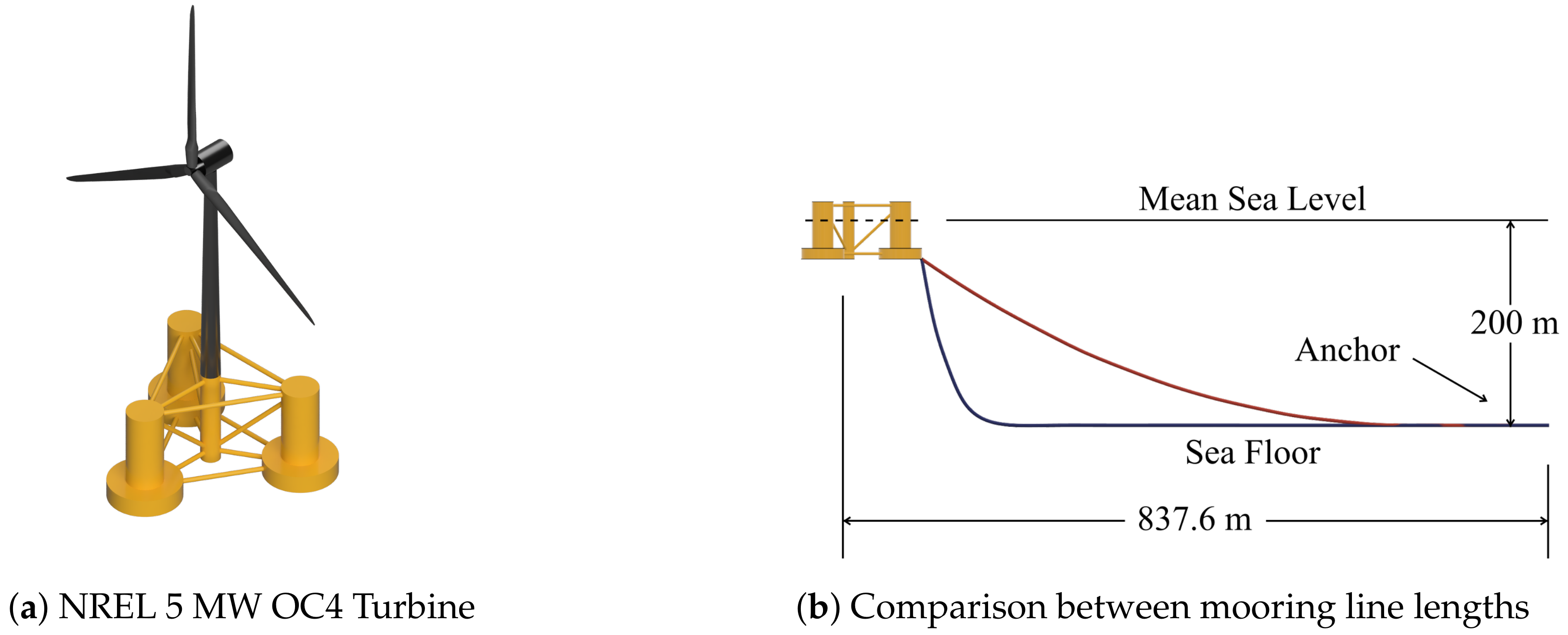
2.1. NREL 5 MW Baseline FOWT

The baseline FOWT to be considered in this paper is illustrated in Figure 1. It is referred to as NREL 5 MW OC4 wind turbine (WT) [29,30]; it was developed by National Renewable Energy Laboratory (NREL) in the US, its rated power is 5 MW, its rated wind speed is 11.4 [m/s] but it can operate between 3 and 25 [m/s], and its platform is a semisubmersible one, as shown in Figure 1a. NREL 5 MW OC4 WT has the manipulable variables for control purpose, namely, nacelle yaw angle γ [rad], three blade pitch angles β : = β 1 , β 2 , β 3 T where β i [rad], i = 1 , 2 , 3 , is the angle for i-th blade, and generator torque τ g [Nm].
This baseline turbine has been widely used for research and development [8,12,31], and a computational tool, called OpenFAST [32], is available for simulating dynamic behaviors of this turbine. For the present work, all the mechanical and electrical properties of the NREL 5 MW OC4 WT are unmodified, except the mooring line length. The length has been extended from 835 [m] (red curve in Figure 1b) to 925 [m] (blue curve in Figure 1b) to enable the large range of platform motion.

2.2. Control Objectives for NREL 5 MW OC4 WT

For the NREL 5 MW OC4 WT, we would like to accomplish the following control objectives simultaneously.
(O1)
Power maximization for below rated wind speed and power regulation for above rated wind speed;
(O2)
Fatigue load minimization;
(O3)
Platform repositioning.
Here, the objectives (O1) and (O2) are standard in all wind turbine control. In fact, there have been many works which develop controllers to attain (O1) and (O2) simultaneously. The objective (O3) is added here to mitigate the wake effect and to optimize the efficiency of a wind farm by dynamically modifying the farm layout.
The floating platform with long mooring lines gives an opportunity to utilize the lateral motion of the platform for wake mitigation within a wind farm. However, by adding the objective (O3), it is not clear that fatigue levels achieved by the controllers without repositioning objective can be maintained at various platform locations. Although there have been some work on position control of FOWTs [2,25,26], so far, no work has considered the addition of fatigue control to a position controlled FOWT.

2.3. Control System Structure

To achieve the control objectives (O1)–(O3), the control system structure depicted in Figure 2 is proposed in this paper.
As shown in the figure, the NREL 5 MW OC4 WT is connected to three sub-controllers, that is, NREL baseline controller for (O1), position controller for (O3), and then fatigue controller for (O2). Next, each controller block will be explained in order. Note that our contribution in this paper is the fatigue controller block, and the other two blocks will be presented below for review purposes only.

2.3.1. NREL Baseline Controller Block

For the control objective (O1), we adopt the baseline controller developed by NREL. This controller uses the generator speed ω g [rad/s] to command the generator torque τ g and the collective blade pitch angle β 0 [rad], in order to maximize the power for low wind speed cases and to regulate the power for high wind speed cases. the NREL baseline controller assumes that the nacelle yaw angle γ is set to face directly into the wind. As such, there is no yaw controller implemented. See Ref. [29] for the details of the baseline controller.

2.3.2. Position Controller Block

The position control block in Figure 2 determines the nacelle yaw angle γ based on the platform position y [m], to reposition the floating platform in the sway direction by manipulating the direction of the aerodynamic thrust force applied on the rotor plane. The controller is fully described in Ref. [28]. It is a proportional-derivative controller whose primary goal is station-keeping of the wind turbine at a desired location, rather than trajectory-tracking from one position to another. Figure 3 shows a top-down view of the FOWT in the x-y plane. For offshore structures, the x and y directions are often referred to as the surge and sway directions, respectively. The figure shows that the FOWT moved some arbitrary distance from its neutral position ( 0 , 0 ) . Specific to this work, we show the position error signal e : = y r e f y which is the difference between the reference sway position y r e f and the current sway position y. Finally, the wind is shown as blowing in the positive surge direction, and this is assumed to be the only wind direction in this paper.
In order to avoid unduly increasing the fatigue load while station-keeping at repositioned locations, we limit the operating range of the nacelle yaw angle γ to the range of ± 20 ° .

2.4. Fatigue Reduction Controller Design Problem

Now, we consider NREL 5 MW OC4 WT combined with NREL baseline controller and position controller, i.e., the dashed-rectangle part in Figure 2, as an augmented system to be controlled. This augmented system has the input vector δ β R 3 , which consists of the three blade pitch angle deviations from the NREL baseline command β 0 . As the sensor outputs of the augmented system, we assume the signals ( y , ω g , ψ i ) are measurable, where y [m] denotes the platform sway position relative to the platform location when there is no wind (see the ( 0 , 0 ) -location in Figure 3), ω g [rad/s] is the generator speed, and ψ i [rad] is the azimuth angle of a specific blade (say the first blade i = 1 ). In addition, we assume the following variables to be available for fatigue feedback control:
x : = [ ( θ p , θ r ) , ( θ ˙ p , θ ˙ r ) , ( d T T , F A , d T T , S S ) , ( d ˙ T T , F A , d ˙ T T , S S ) ] T .
Here, θ p [rad] and θ r [rad] are respectively platform pitch and roll angles, d T T , F A and d T T , S S are the tower-top fore-aft and side-to-side displacements, respectively. See the variables in the simulation tool OpenFAST corresponding to these sensor outputs in Table 1.
For the augmented system, the problem considered in this paper is to design a controller (Fatigue Control block in Figure 2) such that the fatigue loads are reduced at the tower base of the turbine, over operating (i.e., between cut-in and cut-out) wind speeds and at platform positions which correspond to the nacelle yaw angles within ± 20 ° .
Remark 1. 
In this paper, we focus on fatigue loads only at the tower base, for simplicity of discussions. However, we can deal with fatigue loads at other FOWT components analogously, as well as simultaneously with a multi-objective cost function having weighting factors.

3. Fatigue Reduction Controller Design

In this section, we will propose the controller structure for fatigue reduction (Section 3.2) and explain the design of the LQR controller embedded in the controller structure (Section 3.1.3), to solve the design problem in Section 2.4.
Our proposed controller, to be embedded into ‘Fatigue Control’ block in Figure 2, is depicted in the block diagram in Figure 4. Signals and blocks in the block diagram will be explained below. The controller design procedure consists of the following steps.
  • Selection of an operating point;
  • Linearization around the selected operating point;
  • LQR design based on the linearized model.

3.1. Design Steps

3.1.1. Selection of An Operating Point

In this paper, we select three operating points, each of which represents an operating point for below-rated wind speed region (Region 2), transition wind speed region (Region 2.5), and above-rated wind speed region (Region 3). These three points, denoted by v 2 , v 2.5 , and v 3 , are determined by specifying the wind speed and then obtaining the linear model states x in (1).
The software OpenFAST, v2.6.0 which was the latest version when the work in this paper was conducted, developed at the National Renewable Energy laboratory at Golden, CO, US, has the capability of finding the operating point when the operating wind speed is specified. We denote the state x corresponding to the wind speeds v 2 , v 2.5 and v 3 as x 0 , 2 , x 0 , 2.5 and x 0 , 3 , respectively.
Remark 2. 
For the linearization, we fixed the wind turbine at the neutral position with zero nacelle yaw. This is because of the limitation of the linearization using the mooring line model called MAP++ in OpenFAST v2.6.0, which was the most recent version available when this analysis was performed.

3.1.2. Linearization Around the Operating Point

The linearization module in OpenFAST is used to find the linearized model of the WT at each of the three operating points according to wind speed. The linearization module allows for the control variable (generator torque, blade pitch, or nacelle yaw) to be trimmed. In this case, the linearization is performed with a constant rotor speed. Therefore, the trim solution is used only to help the simulation forces converge (i.e., trimming the blade pitch does not change the rotor speed but does change the rotor thrust). The trim solution uses either generator torque or blade pitch depending on which region the model represents. The linearization is performed at many different rotor azimuth positions, which gives the periodic state-space model
δ x ˙ = A ( ψ ) j δ x + B ( ψ ) j δ β , j = 2 , 2.5 , 3 .
We then use MBC3 [33] to convert to a steady-state state-space model by averaging and converting rotating states to non-rotating. In this case, only the B-matrix has rotating states. The final result of the MBC3 process is a constant coefficient model of the form
δ x ˙ = A j δ x + B j δ β N R , j = 2 , 2.5 , 3 .

3.1.3. LQR Design

For providing the blade pitch command δ β in (2), the linear quadratic regulator (LQR) is employed. This is because LQR is suitable to solve the multi-objective (in the sense of minimizing eight states and three inputs) control problem for the multivariable system under consideration.
The LQR controller in the form of
δ β = K δ x N R
is designed using the operating point and steady-state model presented above, and it is tuned by fixing the R-matrix and adjusting only the Q-matrix. The Q-matrix is tuned using an optimization method from Matlab (surrogateopt) that repeatedly adjusts the Q-matrix and tests the controller using turbulent OpenFAST simulations with all states enabled. The optimization searches for a solution which minimizes the fatigue for the given OpenFAST simulations. It searches for a solution using a surrogate model of the actual process. It globally optimizes within user-specified boundaries and is able to handle computationally expensive objective functions and discontinuities.
Due to the nonlinearity of the WT system with respect to the wind speed, we will generate three controllers, namely, a controller for low (below-rated) wind speed K 2 , a controller for high (above-rated) wind speed K 3 , and a controller for middle (around-rated) wind speed K 2.5 . The three controllers are then combined as a gain-scheduling controller and validated in Section 4.

3.2. Fatigue Reduction Controller Structure

The proposed structure of the fatigue reducing controller is shown in Figure 4. The controller is a periodic gain-scheduled controller that is periodic with respect to the rotor azimuth angle ψ and has the generator torque τ g as a gain-scheduling parameter. The matrix T c is the multi-blade coordinate (MBC) transformation matrix [33] given by
T c ( ψ ) : = 1 cos ( ψ ) sin ( ψ ) 1 cos ( ψ + 120 ) sin ( ψ + 120 ) 1 cos ( ψ + 240 ) sin ( ψ + 240 ) .
The MBC transformation matrix is useful for reducing the periodically time-varying control problem into a time-invariant one.
The input to the controller is the plant state vector x . Using the operating point x 0 , the state deviation vector is defined as
δ x : = x x 0

3.3. Design Process Overview

Since the controller design procedure is the same for K 2 , K 2.5 , and K 3 , our explanation will be for a general wind speed region, and the controller to be designed is denoted by K. The design is conducted by solving a short-term fatigue minimization problem:
K = arg min K J ( K )
where the cost function is given by
J ( K ) : = i I D F S T , i ( K ) .
Here, F S T , i is short-term fatigue calculated for i-th environmental profile { ( v i D , w i D ) } , and I D denotes the index set for environmental profiles corresponding to the design environmental conditions { ( v i D , w i D ) } i I D . Each F S T , i ( K ) is based on the calculated LQR gain matrix for that simulation. Therefore, the cost function represents a simple minimization problem where, for a fixed set of simulations, the optimization will search for an LQR gain matrix that results in a minimum fatigue.
The flowchart for the design of K is displayed in Figure 5. The optimization variables are the positive semi-definite matrix Q R 8 × 8 and the positive definite matrix R R 3 × 3 for the quadratic cost function
0 ( δ x T Q δ x + δ β T R δ β ) d t .
First, we give the initial optimization variables, denoted by ( Q 0 , R 0 ) . This, in combination with the linearized model in Section 3.1.2, will lead to the initial linear quadratic regulator gain K 0 . This controller gain is used for simulations with various wind and wave profiles { ( v i D , w i D ) } i I in the medium-fidelity wind turbine simulator OpenFAST [32]. The simulation results are input to the fatigue load calculation software MLife [34], and the objective function in (7) is evaluated. Based on the evaluated objective function, the surrogate optimization algorithm, implemented by the Matlab command surrogateopt.m, will update the weighting matrices ( Q , R ) . The rationale for adopting the surrogate optimization is that it can deal with the optimization of computationally expensive objective functions. The objective function being evaluated here requires running multiple simulations per optimization iteration, leading to long evaluation times. The algorithm will be terminated when either the fatigue is not reduced compared to that in the previous iteration, or the pre-specified maximum number of iterations is reached.
For the optimized controller, denoted by K O P T , the controller analysis is conducted. This analysis step is necessary because the design uses only a small subset of the environmental conditions due to the computational expense to run simulations. In the controller analysis, the fatigue loads are calculated for a comprehensive set of environmental conditions ( v i A , w i A ) i I A , where I A denotes the index set for environmental profiles for the controller analysis.

4. Simulation Results

Up to this point, the control problem and design process have been formulated in a general sense, without taking the specific location of the fatigue to be minimized into account. For demonstration purposes, in this section, we choose the tower base as the location of interest for fatigue minimization. Furthermore, we put no constraints on the fatigue at other locations of the FOWT.
In this section, we will first provide results for the controller design in Section 4.1 based on a subset of possible environmental conditions. Then, we will analyze the designed controller using a larger set of possible environmental conditions in Section 4.2.

4.1. Fatigue Load Controller Design

Due to the computational burden in optimization for controller design which involve one OpenFAST simulation for each environmental condition, the wind and wave conditions used for the design are limited to a small number of ones, as listed in Table 2.
After running the optimization in Figure 5, we obtained the optimal Q with a fixed R = I 3 as
Q O P T = diag ( q i ) , i = 2 , 2.5 , 3 ,
Here, the search region of the matrix Q was limited to the set of diagonal matrices for computational efficiency. The corresponding controller gain matrices are given in Appendix A.

4.2. Fatigue Load Controller Analysis

After the controller design, we analyzed it with a comprehensive set of environmental conditions and a set of sway reference positions y r e f , which are listed in Table 3 and Table 4, respectively.

4.2.1. Environmental Condition Selection

The exact distribution of conditions in Table 3 is chosen based on the FOWT design, and based on a set of metocean data curated by NREL based on real world measurements [35]. The wind speeds are selected to be between 3 and 25 [m/s], which are the cut-in and cut-out wind speeds of the NREL FOWT. The exact wind speeds (4 m/s, 6 m/s etc.) are chosen to match the data layout in Ref. [35]. This reference provides conditional probability distributions for wind speed, wave height, and peak spectral periods, which are used to select the most probable wind and wave conditions. The goal of setting up the simulations this way is to obtain generally realistic environmental conditions, rather than to match a specific set of operating conditions.
The turbulent wind profiles are generated using TurbSim [36], which is software created and distributed by NREL. TurbSim has a number of different settings to adjust, the most important of which are shown in Table 5. The turbulent wave profiles are generated within OpenFAST. The JONSWAP spectrum is used where both the wave height and peak spectral period are varied. Each simulation also uses a unique random seed (different for wind and waves) as part of the turbulence generation, and thus no exact wind profile is used more than once.

4.2.2. Sway Reference Position Selection

Table 4 shows the sway position that the FOWT is commanded to for each wind speed and direction. There are three possible directions of motion including movement in the negative sway direction, zero movement in the sway direction and movement in the positive sway direction. These correspond to the three columns in Table 4 labeled Negative, Zero, and Positive, respectively. It was found in Ref. [5] that, for the NREL FOWT used in this work, the turbine should move 60 [m] (one rotor radius) to reduce the impact of the wake effect of the upstream turbine. Therefore, when commanding nonzero motion, it is ideal that the FOWT is commanded to move this distance. However, at the lowest and highest wind speeds, the rotor cannot generate sufficient thrust to move the full 60 [m]. Therefore, the FOWT is commanded to move as far as possible while obeying the actuator saturation limit of γ = 20 ° .

4.2.3. Fatigue analysis results

Fatigue of the FOWT is compared between the case with position control only (in Figure 6a) and the case with both position and fatigue control (in Figure 6b). In the figure, the following naming conventions used in OpenFAST and given in Table 6, except TwrBaseCombo, are employed.
All plots in Figure 6 are normalized with respect to the fatigue performance of the baseline controller, which corresponds to the 0% fatigue level. Thus, particularly Figure 6b shows the comparison between the baseline controller and the proposed controller. As can be observed in these figures, the fatigue of the tower base was reduced thanks to the optimization, at the expense of increased blade root fatigue. This is consistent with the observation that Namik and Stol made in Ref. [19]. Fatigue load minimization for multiple components would be a future research work.
Fatigue is attributed to three features characterizing the structural oscillations, that is, the mean of each load cycle, the range of each load cycle and the number of cycles. It turned out that the designed controller primarily reduced the range of each load cycle, which led to the reduced fatigue. This reduced range can be seen in Figure 7, which shows the standard deviation of the bending load about the tower base in the x and y directions. We can see that for each wind speed and movement direction the standard deviation was reduced, indicating that the load oscillations became smaller.

5. Conclusions

The main contribution of this paper has been that the turbine repositioning for a semisubmersible floating offshore wind turbine can be achieved while allowing for the inclusion of a fatigue reducing controller. The benefit of such simultaneous repositioning and fatigue reduction is to maximize the effectiveness of the floating offshore wind turbine, thereby minimizing the offshore wind energy cost. To demonstrate this contribution, the LQR-based individual blade pitch controller was optimized robustly over various environmental conditions while the position controller regulated the turbine location. The LQR tuning parameters were optimized through wind turbine dynamic simulations, fatigue calculations, and surrogate optimization. The simulation study using a baseline 5 MW semisubmersible turbine showed that the fatigue damage at the tower base was reduced by about 40% with the addition of the fatigue controller over different operating conditions such as average wind speeds and nacelle yaw angles.
Future research topics for repositioned FOWT fatigue minimization include balancing fatigues at blade roots and tower base, fatigue optimization of multiple turbines in a wind farm, fatigue analysis and controller design for movement (i.e. while dynamically repositioning), and design of controllers gain-scheduled with respect to the nacelle yaw angle.

Author Contributions

Conceptualization, B.S. and R.N.; methodology, B.S.; validation, B.S.; formal analysis, B.S.; data curation, B.S.; writing—original draft preparation, B.S.; writing—review and editing, B.S. and R.N.; visualization, B.S.; supervision, R.N.; project administration, R.N.; funding acquisition, R.N. All authors have read and agreed to the published version of the manuscript.

Funding

This research was funded by the Discovery Grant Program of the Natural Sciences and Engineering Research Council of Canada (NSERC). (Grant No. RGPIN-2017-03753).

Institutional Review Board Statement

Not applicable.

Informed Consent Statement

Not applicable.

Data Availability Statement

Readers interested in the work can email the corresponding author to request data sharing.

Acknowledgments

The authors would like to thank Jason Jonkman and the team at the National Renewable Energy Laboratory for their assistance in the use of OpenFAST and MLife.

Conflicts of Interest

The authors declare no conflict of interest.

Abbreviations

The following abbreviations are used in this manuscript:
FOWTFloating Offshore Wind Turbine
LQRLinear Quadratic Regulator
MBCMulti-Blade Coordinate
NRELNational Renewable Energy Laboratory
WTWind Turbine

Appendix A. Controller Parameters

The designed LQR controller parameters are given below.
K 2 , OPT = 0.063 0.047 0.015 0.029 0.759 0.342 0.313 0.010 0.077 0.027 0.006 0.025 0.723 0.294 0.175 0.023 0.012 0.018 0.005 0.002 0.284 0.075 0.047 0.418
K 2.5 , OPT = 0.025 0.098 0.019 0.030 1.907 2.636 0.092 0.008 0.119 0.024 0.007 0.025 2.842 0.233 0.053 0.031 0.085 0.004 0.008 0.023 2.511 0.027 0.024 0.217
K 3 , OPT = 0.067 0.162 0.037 0.010 0.531 3.673 0.177 0.006 0.058 0.007 0.013 0.007 2.112 0.360 0.094 0.000 0.017 0.001 0.004 0.005 0.742 0.036 0.019 0.074

References

  1. Boersma, S.; Doekemeijer, B.; Gebraad, P.; Fleming, P.; Annoni, J.; Scholbrock, A.; Frederik, J.; van Wingerden, J.W. A tutorial on control-oriented modeling and control of wind farms. In Proceedings of the 2017 American Control Conference (ACC), Seattle, WA, USA, 24–26 May2017; pp. 1–18. [Google Scholar]
  2. Rodrigues, S.; Teixeira Pinto, R.; Soleimanzadeh, M.; Bosman, P.A.; Bauer, P. Wake losses optimization of offshore wind farms with moveable floating wind turbines. Energy Convers. Manag. 2015, 89, 933–941. [Google Scholar] [CrossRef]
  3. Xu, S.; Murai, M.; Wang, X.; Takahashi, K. A novel conceptual design of a dynamically positioned floating wind turbine. Ocean Eng. 2021, 221, 108528. [Google Scholar] [CrossRef]
  4. Yamamoto, I.; Maeda, K.; Asanuma, T. Research On 3-D Dynamic Positioning System For Offshore Platform. In Proceedings of the International Ocean and Polar Engineering Conference, Rhodos, Greece, 17–22 June 2012. [Google Scholar]
  5. Kheirabadi, A.C.; Nagamune, R. Real-time relocation of floating offshore wind turbine platforms for wind farm efficiency maximization: An assessment of feasibility and steady-state potential. Ocean. Eng. 2020, 208, 107445. [Google Scholar] [CrossRef]
  6. Kvittem, M.I.; Moan, T. Time domain analysis procedures for fatigue assessment of a semi-submersible wind turbine. Mar. Struct. 2015, 40, 38–59. [Google Scholar] [CrossRef]
  7. Damiani, R.; Dana, S.; Annoni, J.; Fleming, P.; Roadman, J.; van Dam, J.; Dykes, K. Assessment of wind turbine component loads under yaw-offset conditions. Wind. Energy Sci. 2018, 3, 173–189. [Google Scholar] [CrossRef]
  8. Wang, K.; Chunyan, J.; Xue, H.; Tang, W. Fatigue damage characteristics of a semisubmersible-type floating offshore wind turbine at tower base. J. Renew. Sustain. Energy 2016, 8, 5. [Google Scholar] [CrossRef]
  9. Li, H.; Hu, Z.; Wang, J.; Meng, X. Short-term fatigue analysis for tower base of a spar-type wind turbine under stochastic wind-wave loads. Int. J. Nav. Archit. Ocean Eng. 2018, 10, 9–20. [Google Scholar] [CrossRef]
  10. Stewart, G.; Lackner, M.; Haid, L.; Matha, D.; Jonkman, J.; Robertson, A. Assessing Fatigue and Ultimate Load Uncertainty in Floating Offshore Wind Turbines Due to Varying Simulation Length; Technical Report NREL/CP-5000-58518; National Renewable Energy Laboratory: Boulder, CO, USA, 2013.
  11. Li, L.; Yuan, Z.M.; Ji, C.; Gao, Y. Ultimate structural and fatigue damage loads of a spar-type floating wind turbine. Ships Offshore Struct. 2019, 14, 582–588. [Google Scholar] [CrossRef]
  12. Al Shuwaykh, A.; Sharman, K.T. Analysis of platform motions effect on the fatigue loads and aerodynamic unsteadiness in floating offshore wind turbines. Phys. Conf. Ser. 2020, 1452, 012030. [Google Scholar] [CrossRef]
  13. Lackner, M.A. An investigation of variable power collective pitch control for load mitigation of floating offshore wind turbines. Wind Energy 2013, 16, 435–444. [Google Scholar] [CrossRef]
  14. Fleming, P.A.; Peiffer, A.; Schlipf, D. Wind Turbine Controller to Mitigate Structural Loads on a Floating Wind Turbine Platform. J. Offshore Mech. Arct. Eng. 2019, 141, 061901. [Google Scholar] [CrossRef]
  15. Chaaban, R.; Fritzen, C. Reducing blade fatigue and damping platform motions of floating wind turbines using model predictive control. In Proceedings of the International Conference on Structural Dynamics, Porto, Portugal, 30 June–2 July 2014. [Google Scholar]
  16. Loew, S.; Obradovic, D.; Bottasso, C.L. Model predictive control of wind turbine fatigue via online rainflow-counting on stress history and prediction. Phys. Conf. Ser. 2020, 1618, 022041. [Google Scholar] [CrossRef]
  17. González, H.D.P.; Domínguez-García, J.L. Non-centralized hierarchical model predictive control strategy of floating offshore wind farms for fatigue load reduction. Renew. Energy 2022, 187, 248–256. [Google Scholar] [CrossRef]
  18. Lemmer, F.; Schlipf, D.; Cheng, P.W. Control design methods for floating wind turbines for optimal disturbance rejection. Phys. Conf. Ser. 2016, 753, 092006. [Google Scholar] [CrossRef]
  19. Namik, H.; Stol, K. Individual blade pitch control of floating offshore wind turbines. Wind Energy 2010, 13, 74–85. [Google Scholar] [CrossRef]
  20. Namik, H.; Stol, K. Performance analysis of individual blade pitch control of offshore wind turbines on two floating platforms. Mechatronics 2011, 21, 691–703. [Google Scholar] [CrossRef]
  21. Namik, H.; Stol, K. Individual Blade Pitch Control of a Spar-Buoy Floating Wind Turbine. IEEE Trans. Control Syst. Technol. 2014, 22, 214–223. [Google Scholar] [CrossRef]
  22. Mulders, S.; Pamososuryo, A.; van Wingerden, J. Efficient tuning of Individual Pitch Control: A Bayesian Optimization Machine Learning approach. Phys. Conf. Ser. 2020, 1618, 022039. [Google Scholar] [CrossRef]
  23. Kane, M.B. Machine learning control for floating offshore wind turbine individual blade pitch control. In Proceedings of the 2020 American Control Conference (ACC), Denver, CO, USA, 1–3 July 2020; pp. 237–241. [Google Scholar]
  24. Pustina, L.; Serafini, J.; Pasquali, C.; Solero, L.; Lidozzi, A.; Gennaretti, M. A novel resonant controller for sea-induced rotor blade vibratory loads reduction on floating offshore wind turbines. Renew. Sustain. Energy Rev. 2023, 173, 113073. [Google Scholar] [CrossRef]
  25. Han, C.; Nagamune, R. Platform position control of floating wind turbines using aerodynamic force. Renew. Energy 2019, 151, 896–907. [Google Scholar] [CrossRef]
  26. Escobar Aquino, E.E.; Nagamune, R. H-Infinity position transfer and regulation for floating offshore wind turbines. In Control Theory and Technology; Springer: Berlin/Heidelberg, Germany, 2020. [Google Scholar]
  27. Gao, Y.; Padmanabhan, A.; Chen, O.; Kheirabadi, A.C.; Nagamune, R. A Baseline Repositioning Controller for a Floating Offshore Wind Farm. In Proceedings of the 2022 American Control Conference (ACC), Atlanta, GA, USA, 8–10 June 2022. [Google Scholar]
  28. Saunders, B.; Nagamune, R. Impacts of Mooring Line Lengthening on Position Controller Design for a Floating Offshore Wind Turbine. In Proceedings of the 2022 IEEE International Symposium on Advanced Control of Industrial Processes (AdCONIP), Vancouver, BC, Canada, 7–9 August 2022. [Google Scholar]
  29. Jonkman, J.; Butterfield, S.; Musial, W.; Scott, G. Definition of a 5-MW Reference Wind Turbine for Offshore System Development; Technical Report NREL/TP-500-41958; National Renewable Energy Laboratory: Golden, CO, USA, 2009.
  30. Robertson, A.; Jonkman, J.; Masciola, M.; Song, H.; Goupee, A.; Coulling, A.; Luan, C. Definition of the Semisubmersible Floating System for Phase II of OC4; Technical Report NREL/TP-5000-60601; National Renewable Energy Laboratory: Golden, CO, USA, 2014.
  31. Ward, D.; Collu, M.; Sumner, J. Reducing Tower Fatigue through Blade Back Twist and Active Pitch-to-Stall Control Strategy for a Semi-Submersible Floating Offshore Wind Turbine. Energies 2019, 12, 1897. [Google Scholar] [CrossRef]
  32. NREL. OpenFAST. 2021. Available online: https://github.com/OpenFAST (accessed on 11 May 2021).
  33. Bir, G. User’s Guide to MBC3: Multi-Blade Coordinate Transformation Code for 3-Bladed Wind Turbines; Technical Report; National Renewable Energy Laboratory: Golden, CO, USA, 2010.
  34. Haymann, G. MLife Theory Manual for Version 1.00; Technical Report; National Renewable Energy Laboratory: Golden, CO, USA, 2012.
  35. Stewart, G.M.; Robertson, A.; Jonkman, J.; Lackner, M.A. The creation of a comprehensive metocean data set for offshore wind turbine simulations. Wind Energy 2015, 19, 1151–1159. [Google Scholar] [CrossRef]
  36. Jonkman, B.J. TurbSim User’s Guide: Version 1.50; Technical Report; National Renewable Energy Laboratory: Golden, CO, USA, 2009.
Figure 1. NREL 5 MW OC4 wind turbine.
Jmse 11 02274 g001
Figure 2. Overall block diagram.
Jmse 11 02274 g002
Figure 3. Example of error signal for position control.
Jmse 11 02274 g003
Figure 4. Block diagram of a proposed fatigue controller.
Jmse 11 02274 g004
Figure 5. Flow Chart of Design Process.
Jmse 11 02274 g005
Figure 6. Fatigue damage level compared to the fatigue level (0%) of the NREL baseline controller in percentage.
Jmse 11 02274 g006
Figure 7. Comparison of average standard deviation of tower-base bending moment.
Jmse 11 02274 g007
Table 1. Notations.
Table 1. Notations.
NotationOpenFAST VariableMeaning
yPtfmSwaySway position [m]
ω g GenSpeedGenerator speed [RPM]
ψ i Azimuthi-th blade’s azimuth ( i = 1 , 2 , 3 ) [rad]
θ p DOF_PPlatform pitch angle [rad]
θ r DOF_RPlatform roll angle [rad]
d T T , F A DOF_TFA1Tower-top fore-aft displacement [m]
d T T , S S DOF_TSS1Tower-top side-to-side displacement [m]
Table 2. Simulations run for each fatigue controller optimization.
RegionWind Speed for Linearization [m/s]Wind Speed [m/s]Wave Height [m]Wave Period [s]
Below Rated841.256
61.256
81.256
101.756
Transition12101.756
122.257
142.256
Above Rated18162.258
183.259
203.7510
224.258
Table 3. Selected combinations of environmental conditions.
Wind Speed [m/s]Wave Height [m]Wave Period [s]Wind Speed [m/s]Wave Height [m]Wave Period [s]
40.75[6, 7, 8, 9, 10]182.25[6, 7]
1.25[6, 7, 8, 9, 10] 2.75[6, 7, 8]
60.75[5, 6, 7, 8, 9, 10] 3.25[7, 8, 9]
1.25[6, 7, 8, 9, 10] 3.75[8, 9, 10]
80.75[5, 6, 7, 8, 9]202.75[6, 7, 8]
1.25[6, 7, 8, 9] 3.25[7, 8, 9]
101.25[5, 6, 7, 8] 3.75[8, 9, 10]
1.75[6, 7, 8, 9] 4.25[8, 9, 10, 11]
121.25[5, 6, 7, 8]222.75[5, 6, 7]
1.75[6, 7, 8] 3.25[7, 8, 9]
2.25[7, 8, 9, 10] 3.75[7, 8, 9]
141.75[5, 6, 7, 8] 4.25[8, 9, 10]
2.25[6, 7, 8, 9] 4.75[9, 10, 11]
161.75[5, 6, 7]242.751
2.25[6, 7, 8] 3.255
2.75[7, 8, 9] 3.75[6, 7]
4.25[7, 8]
Table 4. Commanded positions at each wind speed.
Wind Speed [m/s]Commanded Position [m]
NegativeZeroPositive
4−20020
6−40040
8−60060
10−60060
12−60060
14−60060
16−60060
18−60060
20−55055
22−50050
24−40040
Table 5. TurbSim wind profile parameters.
TurbSim NameParameter Choice
TurbModelIECKAI
IECstandard3
IECturbcB
IEC_WindTypeNTM
ProfileTypePL
PLExpdefault
Z0default
Table 6. Description of the fatigue labels.
NameMeaning
RootMEdgEdgewise bending fatigue at the blade root
RootMFlpFlapwise bending fatigue at the blade root
RotTorqTorsional fatigue on the rotor shaft
LSSGagMyaBending fatigue on the rotor shaft
TwrBsMxtBending fatigue about the tower base x-axis
TwrBsMytBending fatigue about the tower base y-axis
TwrBaseComboSum of bending fatigue about the tower base axes
Disclaimer/Publisher’s Note: The statements, opinions and data contained in all publications are solely those of the individual author(s) and contributor(s) and not of MDPI and/or the editor(s). MDPI and/or the editor(s) disclaim responsibility for any injury to people or property resulting from any ideas, methods, instructions or products referred to in the content.

