Article

Parameter Optimization and Performance Research: Radial Inflow Turbine in Ocean Thermal Energy Conversion

1
School of Mechanical Engineering, Key Laboratory of High-Efficiency and Clean Mechanical Manufacture of Ministry of Education, National Demonstration Center for Experimental Mechanical Engineering Education, Shandong University, Jinan 250061, China
2
Institute of Marine Science and Technology, Shandong University, Qingdao 266237, China
*
Authors to whom correspondence should be addressed.
J. Mar. Sci. Eng. 2023, 11(12), 2293; https://doi.org/10.3390/jmse11122293
Submission received: 31 October 2023 / Revised: 21 November 2023 / Accepted: 1 December 2023 / Published: 3 December 2023
(This article belongs to the Section Ocean Engineering)

Abstract

:
Combining one-dimensional parameter optimization and three-dimensional modeling optimization, a 30 kW radial inflow turbine for ocean thermal energy conversion was designed. In this paper, the effects of blade tip clearance, blade number, twist angle, and wheel–diameter ratio on the radial inflow turbine were analyzed. The results show that the model prediction method based on 3D numerical simulation data can effectively complete secondary optimization of the radial turbine rotor. The prediction model can be used to directly obtain the optimal modeling parameter of the rotor. The tip clearance, blade number, twist angle, wheel–diameter ratio, and shaft efficiency were found to be 0.273 mm, 16, 43.378°, 0.241, and 88.467%, respectively. The optimized shaft efficiency of the turbine was found to be 2.239% higher than the one-dimensional design result, which is of great significance in reducing the system’s power generation costs and promoting the application of this approach in engineering power generation using ocean thermal energy.

1. Introduction

Ocean thermal energy conversion (OTEC) is the main method of using ocean thermal energy to generate electricity. The principle of this approach’s function lies in using the warm water on the surface of the ocean to heat low-boiling-point working mediums to gasify them; alternatively, the pressure is reduced, allowing the sea water to vaporize, driving a turbine and producing electricity. At the same time, the cold sea water extracted from the seabed is used to condense the steam into liquid again so that a circulation system is formed [1].
The radial inflow turbine is a power component that is widely used in the field of OTEC. It has many advantages, such as compact structure, a large single-stage enthalpy drop, a high rotational speed, strong adaptability to variable working conditions with variable guide stator vanes, and a high operating efficiency under small-flow conditions [2,3,4,5]. At present, research achievements made by domestic and foreign scholars on OTEC system radial inflow turbines are gradually increasing. These researchers have been focusing on the aerodynamic design, working medium selection, parameter optimization algorithm, profile design method, loss model, and performance prediction of variable working conditions. For example, Nithesh et al. [6] designed a 2 kW OTEC turbine with an R134a working medium. The three-dimensional flow field of this turbine was numerically simulated using CFX and differences in the flow characteristics of small-sized turbines with different blade thicknesses, blade tip clearances, and blade edge shapes were given. Yue et al. [7] designed a toluene medium radial inflow turbine for a medium–high-temperature solar-power-generation system based on the organic Rankine cycle (ORC). In addition, CFD simulations of the turbine were carried out. The simulation results showed that there were some shock losses at the stator outlet. Li et al. [8] systematically introduced a one-dimensional aerodynamic design method based on the screening method, which can select the initial parameters of a radial inflow turbine, design the turbine’s scheme, and improve the turbine’s performance. Moreover, the value range of the design parameters was given by comprehensively considering the turbine flow characteristics and engineering experience. According to the actual physical properties of five organic working mediums and a screening method, Li Yan et al. [9] wrote a program for the design and performance prediction of radial inflow turbines under varying working conditions. The optimum design of radial turbine with an R123 working medium and an expansion ratio of 8 was carried out. The optimum design method and variable operating condition prediction method of a non-standard radial turbine with a large expansion ratio were discussed. Chen et al. [10] studied the stator blade installation angle of a 100 kW ammonia working medium radial inflow turbine. Through CFD calculation, it was concluded that the turbine’s efficiency increased initially and then decreased when the installation angle was changed from 30° to 60°; the turbine efficiency was high. Ge et al. [11] used a genetic algorithm to design the parameters of a 7.5 kW ammonia working medium radial inflow turbine. Through flow field simulation between the adjustable stator blades, it was concluded that the turbine performance was optimal when the stator blades were installed at 37°. Ding et al. [12] designed a 3 kW ocean thermal energy radial inflow turbine and conducted some research on its variable working condition performance and the optimization of the radial clearance between the rotor and the stator. The problem of the velocity of the working medium along the circumference having an uneven distribution at the stator outlet was effectively solved.
In terms of loss calculation, Persky et al. [13] developed a loss model matching method for analyzing CO2 and the performance of an R143a working medium turbine. They proposed a loss model with higher accuracy through the preferred physical model and the data were derived directly from their experiment. The maximum error between the model prediction result and the numerical simulation result was less than 2%. This method can realize the performance evaluation of turbines under off-design conditions. Fiaschi et al. [14] designed a radial inflow turbine for an ORC system; they compared the effects of six different working mediums on the turbine’s performance. The researchers showed that the R134a working medium could achieve the highest efficiency of 0.85 and the loss distribution that was observed using different working mediums was consistent. Otherwise, the secondary flow loss caused by the high curvature of the rotor accounted for the main part of the performance loss. Wang et al. [15] analyzed the vortex structure near the upper and lower walls in the stator and in the flow channel; they pointed out that the secondary flow in the stator mainly exists at the backpressure surface behind the flow channel. The axial and radial distribution of the total pressure loss coefficient was also given. Han et al. [16] studied the loss changes of a radial inflow turbine with a 150 °C heat source and an R245fa working medium. This researcher showed that, when the heat source temperature decreased, the friction loss increased, but the stator loss and rotor loss remained basically unchanged. Zhang et al. [17] used a dimensionless quantity to describe the tip clearance size and analyzed the internal flow law of the tip clearance and the influence of the tip clearance on the radial inflow turbine. Nithesh et al. [18] studied the effect of the number of rotor blades on a turbine’s performance through different schemes; the paper showed that the number of blades affected the turbine’s performance through affecting the effective flow area and the recirculation area.
In terms of performance optimization under variable operating conditions, Kumar et al. [19] used a sensitivity assessment method to analyze the geometric parameters affecting turbine performance based on different loss models. On this basis, an artificial neural network model was established to predict the maximum efficiency range of the turbine. Bahadormanesh et al. [20] introduced the stress and vibration constraints and proposed an optimal turbine speed calculation method based on the firefly algorithm. Zhai et al. [21] adopted a constrained genetic algorithm (GA) to optimize the radial inflow turbine. Based on four working mediums—pentane, R245fa, R365mfc, and R123—the influence of heat source outlet temperature on the design parameters of the radial inflow turbine and the performance of the ORC system was studied. Kiyarash et al. [22] proposed a new method combining mean line modeling and DIRECT optimization for small radial inflow turbines. This method can obtain dynamic efficiency based on turbine losses and then quickly screen turbine size parameters under different working conditions.
Although there has been substantial research on OTEC radial inflow turbines, most researchers focus on the optimization of initial parameters and loss coefficient and less on the modeling parameters influence of performance. Therefore, based on the one-dimensional design scheme, CFX simulation, and the support vector regression method, the present study carried out a secondary optimization of the rotor modeling parameters of the radial inflow turbine. In addition, this research compared the two schemes before and after optimization and described the influence of modeling parameters on turbine performance.

2. Materials and Methods

2.1. Turbine Aerodynamic Design

2.1.1. Circulation System Parameters Selection

The inlet and outlet working conditions of the radial turbine were determined through the circulation system. The annual average temperature of the surface water in the South China Sea is in the range of 24.6~30.1 °C and the temperature of the cold sea water below 800 m is generally stable at about 4 °C. The inlet and outlet temperature difference of seawater in the heat exchanger is 2~4 °C. In order to maintain the power consumption of the warm sea pump and the cold sea pump at a low level, the terminal temperature difference of medium and large OTEC evaporator is generally 2 °C [23]. The pipe friction loss from the evaporator to the turbine and the fluctuation of the turbine inlet condition were ignored. According to the evaluation of the five different working substances in presented in [24], the net power generated using R134a in the highest performance cycle is higher than that generated using n-pentane and other working substances. In addition, R134a has the characteristics of low critical pressure, low critical temperature, low flammability, low toxicity, and low impact on the environment [25]. It was selected as the circulating working medium and its physical parameters were obtained through invoking NIST REFPROP V9.1, the international authoritative database of working mediums and their physical properties. We chose organic Rankine cycle as the system circulation mode, and the circulation system diagram is shown in Figure 1. The system thermal parameters were determined using cyclic calculation. The calculation model we used is the model mentioned in [26] and the results are shown in Table 1.

2.1.2. Parameters Optimization and Design Results

According to the system parameters presented in Table 1, the one-dimensional design model of the radial inflow turbine was established using a screening method and the isentropic efficiency of the radial inflow turbine was calculated using the loss model [27]. In the above process, the flow losses of the working medium in the volute were ignored. Otherwise, we used the ISIGHT 2020 software to carry out optimal Latin hypercube sampling of seven initial parameters. The sampling results were input into the one-dimensional design program written by MATLAB 2020b. With the goal of attaining an isentropic efficiency greater than 85%, the thermodynamic parameters optimization results of the radial inflow turbine were obtained through iteration. On this basis, a data regression prediction method was used to optimize the modeling parameters of the radial inflow turbine rotor. The process is shown in Figure 2.
Multiple one-dimensional design schemes of the radial inflow turbine were obtained through iterative calculations [28]. After checking, the schemes which were found to now meet the structural strength requirements, or ones in which the outlet relative speed was less than inlet relative speed, were eliminated. The one-dimensional design scheme with the highest isentropic efficiency of the remaining schemes was selected as the initial scheme of modeling optimization. The parameters of the initial scheme are shown in Table 2.

2.2. Numerical Simulation of Radial Turbines

Although the one-dimensional design of the radial inflow turbine can obtain the optimal parameters of the rotor, the calculation of its isentropic efficiency is based on the loss model. The calculation results cannot fully reflect the viscous and unsteady characteristics of the flow of organic working fluid in the radial inflow turbine. Therefore, based on the three-dimensional numerical simulation results, 40 groups of training samples were established in this research and the regression prediction method was used to optimize the turbine rotor parameters, so as to further improve the performance of the initial scheme.

2.2.1. Three-Dimensional Modeling

Based on the one-dimensional design results in Table 2, in this study, we designed the volute using the equal circulation method; we selected the TC-2P subsonic radial blade type for the blade. The three-dimensional modeling of the volute and stator was completed using SolidWorks. The rotor modeling was completed with reference to Ansys-Bladegen [29]. The three-dimensional model of the initial scheme is shown in Figure 3.
The rotor is the core moving part of a radial inflow turbine, and its efficiency is much lower than those of the volute and the guide vane. Optimizing the design of the rotor is the focus of the radial inflow turbine optimization design. This paper first used Isight to perform Latin hypercube sampling on seven shape parameters of the rotor: wheel–diameter ratio D ¯ 2 , blade number Z 2 , blade twist angle θ , radial clearance 1 , blade tip clearance 2 , blade outlet thickness T 2 , and blade outlet fillet radius r [30]. The sampling range of the seven parameters was set according to [8], as shown in Table 3. The definition of D ¯ 2 is shown in Equation (1), and the schematic diagram of other parameters is shown in Figure 4.
D ¯ 2 = D 2 2 + D 2 2 2 D 1
The wheel–diameter ratio D ¯ 2 is the ratio of the rotor outlet average diameter to the rotor inlet diameter, which reflects the relative size of the rotor inlet and outlet diameters. The authors of [21] pointed out that the wheel–diameter ratio has an important influence on the flow channel shape and the blockage coefficient of the inlet and outlet. The blade number Z 2 and blade twist angle θ have an impact on the off-design performance of the radial inflow turbine. While radial clearance 1 and blade tip clearance 2 are too large, they will both cause internal leakage loss to increase. When 1 is too small, it will cause uneven mixing of the working fluid when it flows out of the stator, resulting in secondary flow loss [31]. When 2 is set by equal clearance, if it is too small, it will cause the blade to contact with the rotor shell during the transient process of rotation and heat transfer, resulting in large friction loss. The blade outlet thickness T 2 and blade outlet fillet radius r mainly affect the turbine shaft efficiency by affecting the wake and residual velocity of the airflow.

2.2.2. Numerical Simulation Settings

We used the professional rotating machinery simulation software Ansys-CFX 2020 R2 to perform a three-dimensional viscous flow steady-state simulation of the radial inflow turbine. For robustness, we used a first-order upwind scheme to discretize the Reynolds-averaged Navier–Stokes (RANS) equations. The k - ε model was selected as turbulence modeling for its scalable wall function, fine stability, and fast convergence, which has been widely used in the fields of aviation and turbomachinery [32,33]. Details of the governing equations used in this study can be found in the ANSYS CFX-Solver Theory Guide [34]. The boundary conditions were set according to Table 1: inlet total pressure—0.64 MPa; inlet total temperature—297.15 K; outlet static pressure—0.393 MPa; mass flow rate—3.82 kg/s. The connection between the volute and the stator was static, and the options Frame Change/Mixing and Pitch Change were set to Stage and Automatic, respectively; the connection between the stator and the rotor was dynamic and was defined as a frozen rotor model [35]. In addition, all walls were set as no-slip boundaries, the wall roughness was set as Ra3.2, and the numerical calculation convergence residual was set as 10−6. Timescale control option was set to auto timescale, the length scale option was set to conservative, and the timescale factor was set to the value of one.

2.2.3. Mesh Generation

The volute was meshed with tetrahedral elements using Ansys-ICEM 2020 R2, and the grid was partly refined at the tongue. The stator model was imported into Ansys-Turbogrid using a configuration file to generate a single-channel structured grid, and then a full-channel grid was generated using Ansys-ICEM. The initial scheme and the other 40 rotor models were directly parameterized using Ansys-Bladegen and then imported into Turbogrid and ICEM to generate single-channel and full-channel structured grids [18]. The value of y+ associated with the near-wall element size specification was set to 30. The single-channel grids of the stator and rotor of the initial scheme are shown in Figure 5.
In order to ensure sufficient accuracy of the numerical simulation results, this paper used the same grid-generation method for all schemes, and used ICEM to check the grid quality. Total grid number of the first scheme of the 40 schemes was set to 10.5 million based on the grid quality, and then grid independence verification was performed on this basis. The verification result of Scheme 1 is shown in Figure 6, and the verification process of other schemes was similar to it. The results showed that, after the grid number of 9 million, increasing the grid number had little effect on the results, indicating that the grid number set could meet the accuracy and independence requirements. The grid numbers of the volute and stator set were 700,229 and 4,309,184, respectively, and the rotor grid number range was 4,553,272~5,658,086.

2.3. Optimized Method of Radial Turbines—Data Regression Prediction Based on Support Vector Machine

Support vector regression (SVR) is one of the most commonly used machine learning regression methods; it has a rigorous statistical theory foundation and has high robustness in dealing with complex problems such as small samples, nonlinear regression, and multiple features; additionally, it has excellent generalization ability [36]. When dealing with high-dimensional problems, SVR can be used to effectively reduce the computational consumption by choosing a suitable kernel function. Compared with other methods such as neural network regression and random forest regression, SVR has the advantages of easy implementation, computational complexity independent of the input space dimension, and high prediction accuracy. It has been successfully applied in many fields.
In order to achieve stable prediction of radial turbine efficiency using different modeling parameters, this study used the above numerical simulation data to establish a training sample library; further, we obtained an SVR model through training. The SVR model adopts radial basis function as the kernel function [37], and the mathematical model is as follows:
The sample set is x 1 , y 1 , x 2 , y 2 , , x 40 , y 40 . The independent variable is x i R 7 and it contains 7 rotor modeling parameters. y i R and it is the dependent variable of the sample set. The data x 1 , x 2 , , x 40 can be mapped to a higher dimensional space through a nonlinear mapping method and the regression function can be defined as follows:
f x = ω T Φ x + b
In addition, ω , Φ x , b are the weight vector, the mapping transformation to a high dimensional space, and the offset. The above problem can be transformed into a quadratic programming problem through introducing Lagrange multipliers. The objective function and constraints of this problem are constructed as Equations (3) and (4) [38].
m i n 1 2 ω 2 + c i = 1 m ξ i , ξ i *
s . t . f x i y i ε + ξ i y i f x i ε + ξ i * ξ i , ξ i * 0 , i = 1,2 , , m
In the equations above, c , ε are penalty factor, insensitive loss coefficient and ξ i , ξ i * are the relaxation factors. Through introducing Lagrange multipliers α i and α i * , the objective function can be reduced as Equation (5).
f x = i = 1 m α i , α i * K x i , x + b
K x i , x is RBF kernel function, calculated by Equation (6).
K x i , x j = exp x i x j 2 2 σ 2

3. Results

3.1. Numerical Simulation Results

Figure 7 shows the simulation results of the 3D streamline distribution and pressure distribution of the radial inflow turbine initial scheme.
As shown in Figure 7a, the working fluid flow in the turbine is stable, and the streamlines are evenly distributed in each channel. There is no large-scale swirling vortex or flow disturbance. The working fluid flows into the stator evenly with a certain circumferential angle, and gradually accelerates in the stator channel, reaching the maximum value at the outlet. The average outlet velocity is about 104.4 m/s, and the velocity is not completely evenly distributed along the circumferential direction, which is caused by the small radial clearance, but there is no transonic flow phenomenon at the stator outlet. The working fluid flows into the rotor with a relative flow angle close to 90°, and gradually decelerates until it flows out of the outlet, producing small shock loss and residual velocity loss. As shown in Figure 7b, the pressure inside the turbine decreases gradually along the flow direction, and the pressure gradient is basically consistent with the flow direction. The working fluid pressure drops in the stator, and the flow velocity increases. In the rotor, it further expands to drive the rotor to rotate and do work.
Considering various internal losses of radial inflow turbines, shaft power P T and shaft efficiency η P were used as the criteria to evaluate the power performance of radial inflow turbines when optimizing rotor modeling. P T and η P were calculated by the following two equations.
P T = T r n 9549  
η P = P T m h s = P T m ( i 0 i 2 s )
In addition, T r , n , m , h s , and i are the torque, speed, mass flow, isentropic enthalpy, and enthalpy value, respectively. T r , n , h s , and i are obtained through the CFD results. The units of T r , n , and P T are N·m, r/min, and kW, respectively.
Based on CFD-Post 2020 R2 software, simulation results of 40 schemes were obtained through the batch post-processing method. The simulation results of the shaft power are distributed between 31.5 kW and 35.0 kW, and the degree of dispersion is not high.

3.2. Model Training and Optimization Results

Through the SVR model, we can establish a nonlinear mapping relationship between the seven rotor shape parameters and the radial inflow turbine shaft efficiency and we can obtain the shaft efficiency prediction results. Different from the one-dimensional model, this model is a non-parametric model based entirely on the numerical simulation results; it does not need to give the specific calculation process from the rotor shape parameters to the shaft efficiency results. Ten sets of radial inflow turbine rotor shape parameters were arbitrarily given, and the actual values of shaft efficiency were obtained through the same modeling and simulation process; these were used as a test set to verify the accuracy of the SVR model. The comparison of the shaft efficiency prediction results for the training set and the test set is shown in Figure 8.
As can be seen from the figure, there is some error between the predicted value and the simulation result. The test set error is slightly larger than the training set error, but it is also below 0.5%, which indicates that 40 training samples can meet the prediction accuracy requirements.
In order to find the rotor shape parameters that can maximize the radial inflow turbine shaft efficiency, we performed a full-factor sampling in the value range of the rotor shape parameters using the MATLAB program; next, we input all the parameter combinations into the above SVR model, and then used a genetic algorithm to screen the prediction results. The optimal rotor shape scheme under the rated condition was obtained, and the optimization results are shown in Table 4.

3.3. Influence of Modeling Parameters on Turbine Performance

To avoid the possibility that the optimal shape parameters obtained are “isolated” points in the parameter space, it is necessary to analyze the influence trend of the adjacent shape parameters on the performance. The sensitivity of the input parameters to the shaft efficiency in the regression prediction model was calculated using the experimental design module in the Isight 2020 software, and the results are shown in Figure 9. As can be seen from the figure, the first four parameters have the greatest impact on the shaft efficiency.
The blade tip clearance 2 , blade number Z 2 , wheel–diameter ratio D ¯ 2 , and twist angle θ were taken as variables, and the other parameters were kept consistent with those in Table 4. The distribution maps of the shaft efficiency with the wheel–diameter ratio and the twist angle at different blade numbers and blade tip clearances were drawn, as shown in Figure 10, Figure 11 and Figure 12. These figures show that, for different rotor blade numbers and blade tip clearances, the surface shape of shaft efficiency distribution is similar, and there will always be a maximum value of shaft efficiency, which is not an isolated parameter point. Near this value, the shaft efficiency changes continuously with the wheel–diameter ratio and twist angle.
Figure 10 shows the change in the radial inflow turbine shaft efficiency with the twist angle and the wheel–diameter ratio when the blade tip clearance is 0.273 mm and the blade number is 16. As can be seen from the figure, at the upper and lower limits of the allowable range of the wheel–diameter ratio and the twist angle, the shaft efficiency decreases to a certain extent; when both the wheel–diameter ratio and the twist angle tend to the upper limit of the allowable range, the radial inflow turbine shaft efficiency will drop rapidly. This should be avoided as much as possible in the design process. As can be seen from Figure 11, when the blade number is 16, the peak value of shaft efficiency corresponds to a twist angle range of 42°~46° and a wheel–diameter ratio range of 0.385~0.420. When the blade tip clearance value is less than 0.273 mm, the change in the shaft efficiency with a clearance value is very small. When the blade tip clearance value is greater than 0.273 mm, the influence of blade tip clearance on shaft efficiency increases, and the peak value of shaft efficiency gradually moves to a smaller wheel–diameter ratio and a larger twist angle area. Considering the actual processing difficulty and off-design operating conditions, a blade tip clearance greater than 0.273 mm is preferred. Figure 12 shows the influence of different blade numbers (14~19) on radial inflow turbine performance when rotor blade tip clearance is 0.273 mm. It can be seen that, as the number of blades increases, the shaft efficiency first increases and then decreases, and when there are 16 blades, it can achieve optimal performance. In addition, the blade number has a relatively independent effect on radial inflow turbine shaft efficiency. When the blade number changes, the wheel–diameter ratio corresponding to the peak value of the shaft efficiency hardly changes, and the corresponding twist angle change range is less than 2°.

4. Discussion

4.1. Comparative Analysis of Optimization Scheme Performance

Figure 13a,b show the streamline distribution and static entropy distribution at 50% blade height of the rotor before optimization. It can be seen that the suction surface of the rotor obtained from the one-dimensional design always has recirculation vortices of different sizes, which cause the flow in the rotor passage to be uneven, and subject the blades to unsteady cyclic loads, reducing the efficiency and strength of the turbine. The suction surface vortices are mainly caused by the mismatch between the operating speed, blade geometry parameters, and rotor shape parameters.
Figure 13c,d show the flow field and static entropy contour of the optimized rotor model. From the streamline plot, it can be seen that the recirculation vortices on the suction surface of the blade almost disappear, and the overall streamline distribution is more uniform. In the entropy contour plot, the entropy increase amplitude in the passage is significantly reduced, and the entropy increase from the stator inlet to the rotor outlet is reduced by 0.28 J/(kg·K). This indicates that using the regression prediction method to optimize the rotor shape with the highest shaft efficiency as the objective can effectively avoid the vortex structure on the suction surface of the blade, achieve the adaptation of shape parameters and speed, and reduce losses.

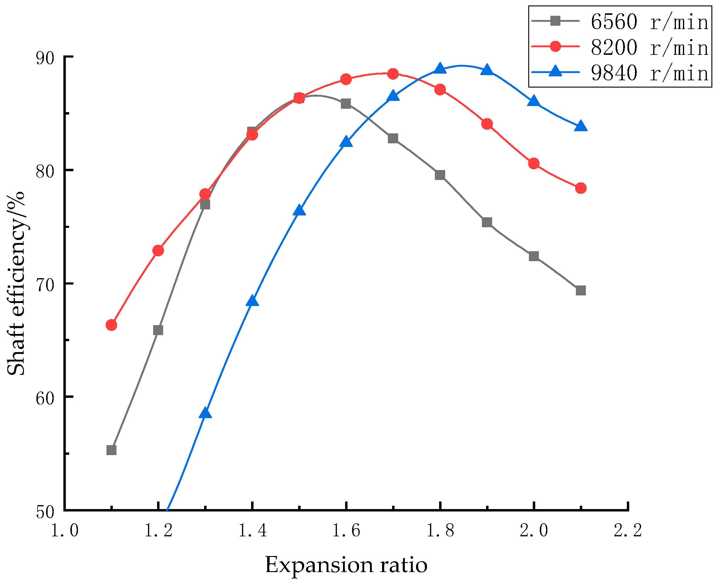
4.2. Performance Analysis of Variable Working Conditions

In actual sea conditions, the seawater temperature at the ocean surface will change in accordance with factors such as light intensity and season, which will cause the inlet condition of the radial inflow turbine to be inconsistent with the design condition. Therefore, it is necessary to analyze the performance of the radial inflow turbine under variable conditions. This paper simulates the shaft efficiency distribution of the optimized radial inflow turbine under different inlet conditions and speeds using CFX 2020 R2 software. The curves, fitted according to the simulation results under multiple conditions, are shown in Figure 14; here, the boundary condition assumes that the static pressure at the turbine outlet is constant. The numerical simulation speeds include three groups of values: design speed and design speed plus or minus 20%. The inlet conditions are all saturated conditions corresponding to each expansion ratio. It can be concluded from Figure 14 that the shaft efficiency of the radial inflow turbine increases first and then decreases with the increase in the expansion ratio. For different speeds, the corresponding expansion ratios that reach the peak shaft efficiency are not the same; the higher the speed, the larger the expansion ratio. When the operating speed is 80% of the design speed, 100% of the design speed, and 120% of the design speed, the turbine efficiency reaches its peak at expansion ratios of 1.53, 1.70, and 1.85, respectively, which are 86.337%, 88.509%, and 88.736%, respectively. The optimized radial inflow turbine operates at design speed, and the shaft efficiency changes a little with the expansion ratio. Although its performance is weaker than that of the high-speed operation mode at a large expansion ratio, its performance degradation at low and high temperatures is not large, and its overall performance is excellent.

5. Conclusions

Based on the one-dimensional design of a 30 kW ocean thermal energy radial inflow turbine, this paper used a three-dimensional numerical simulation method to study the effects of different rotor shape parameters on the working fluid flow and performance at the rated condition, and used the machine learning method to optimize the rotor shape parameters. The main conclusions are as follows:
(1)
A 30 kW ocean thermal energy radial inflow turbine was designed, and a one-dimensional design optimization was performed using Isight 2020 and Matlab 2020b, obtaining the optimal scheme based on seven initial thermodynamic parameters, with a shaft efficiency of 86.228%. Based on the numerical simulation carried out using the CFX 2020 R2 software, this paper obtained radial inflow turbine models with different rotor shapes using parameterization and batch processing methods and analyzed their performance parameters.
(2)
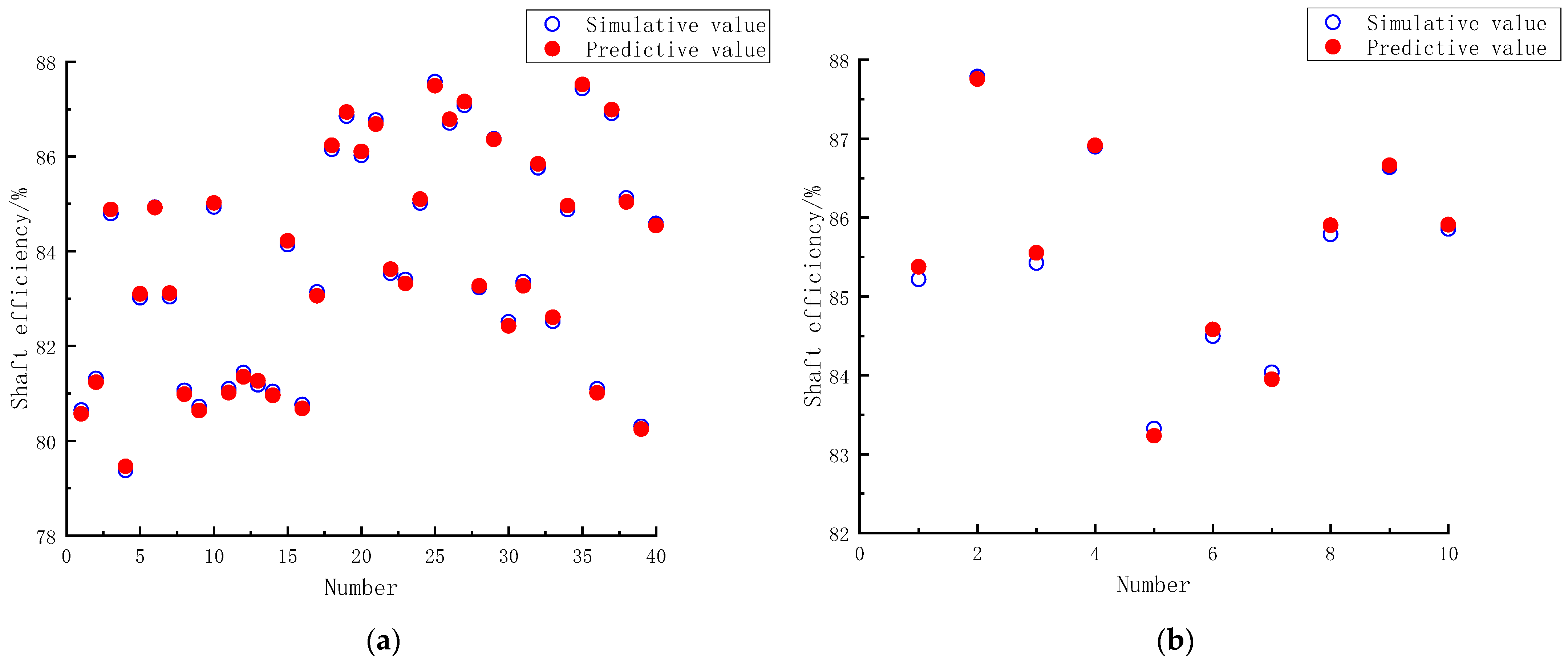
Based on the one-dimensional optimal scheme, the rotor shape parameters were further optimized based on the support vector regression method, achieving the best adaptation of the rotor shape parameters, stator geometry parameters, and design condition. The regression prediction method used does not require a prior model and can directly obtain the nonlinear mapping relationship between the shape parameters and the shaft efficiency. The optimized rotor results are as follows: diameter ratio—0.421; blade number—16; twist angle—43.378°; radial clearance—2.553 mm; blade tip clearance—0.273 mm; blade thickness—1.582 mm; outlet blade fillet radius—3.152 mm.
(3)
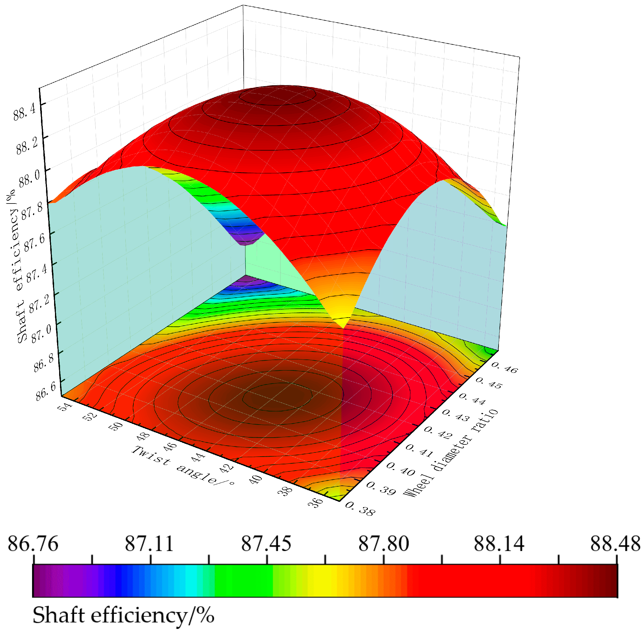
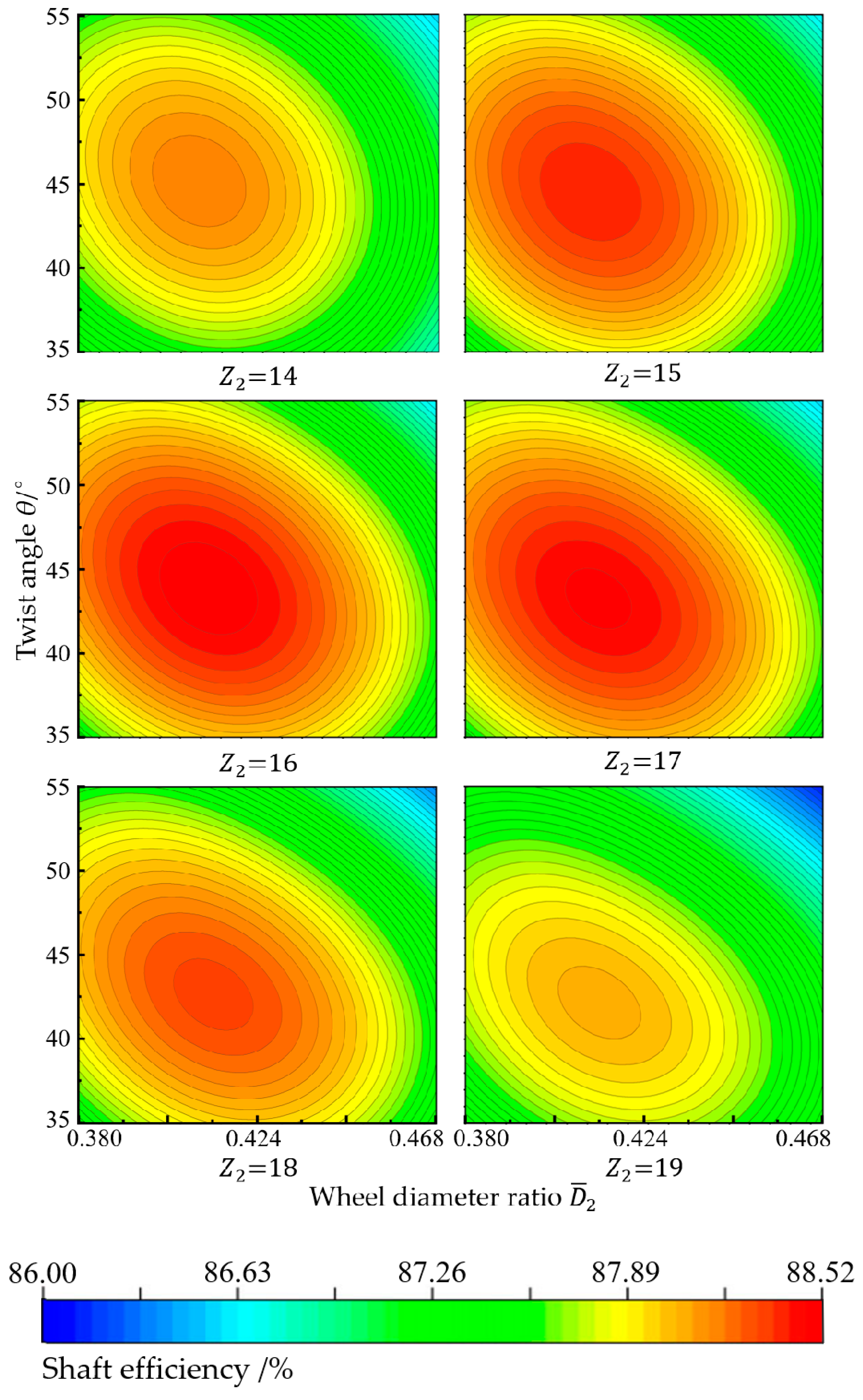
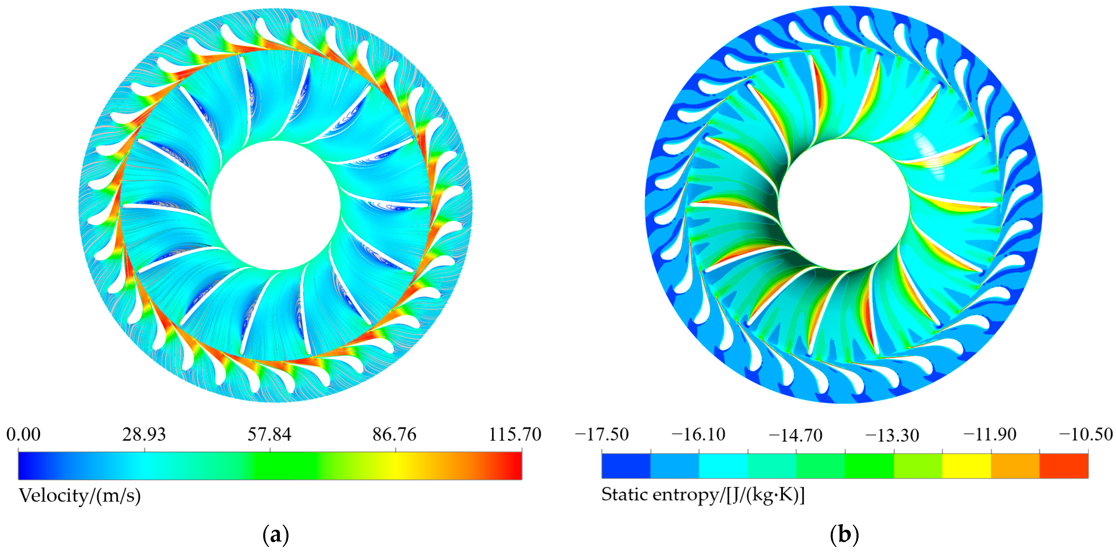
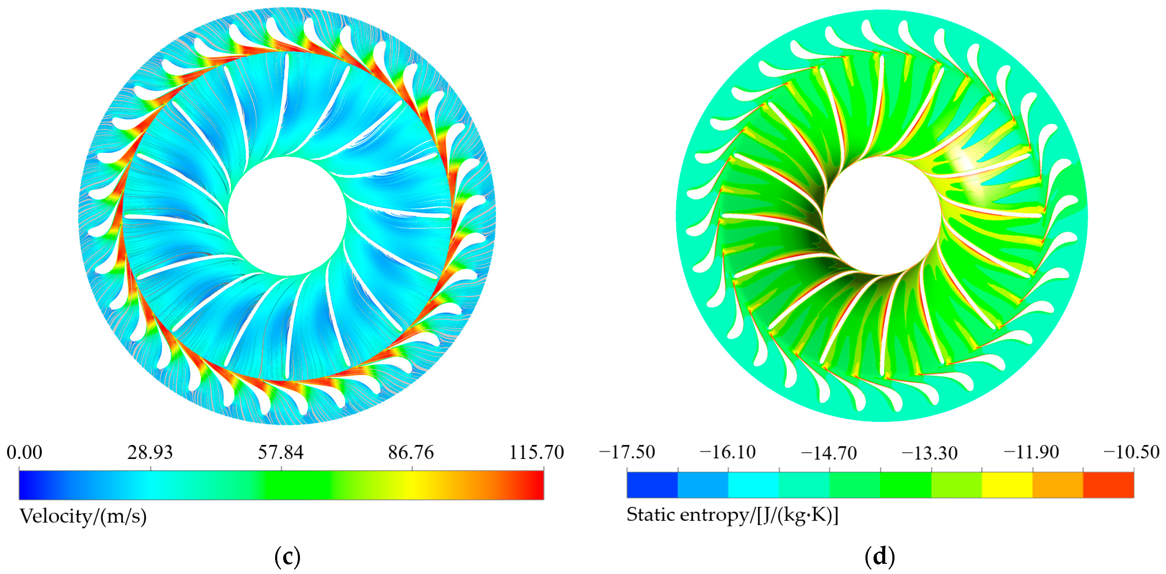
The radial inflow turbine scheme obtained through using the model prediction method can effectively avoid the recirculation vortices on the suction surface of the moving rotor. The maximum shaft efficiency of the optimized scheme is 88.467%, which is 2.239% higher than that of the one-dimensional design optimal scheme, effectively improving the flow uniformity of the turbine and increasing its service life. This paper studied the influence of shape parameters on the shaft efficiency of the radial inflow turbine, revealing the coupling relationship between blade tip clearance, blade number, diameter ratio, and twist angle. Among them, the blade tip clearance of the rotor is the key factor that determines the output shaft efficiency of the turbine. For different diameter ratio and twist angle schemes, there is a maximum value of shaft efficiency, and this point will change with the change in blade tip clearance and blade number. In further research, the blade angle of the stator also needs to be adjusted by the prediction method, so as to make the optimization scheme more accurate.

Author Contributions

Conceptualization, software, methodology, data curation, writing—original draft preparation and validation, Y.W.; conceptualization, supervision, and funding acquisition, Y.L.; writing—review and editing, Y.C. and G.X.; project administration, T.Z. All authors contributed to the design of the study. All authors discussed, read, edited, and approved the article. All authors have read and agreed to the published version of the manuscript.

Funding

This research was funded by the Marine Carbon Sink and Biogeochemical Process Research Center, National Natural Science Foundation of China, Project number: 42188102 and Southern Marine Science and Engineering Guangdong Laboratory (Zhanjiang), Project Number: ZJW-2019-05.

Institutional Review Board Statement

Not applicable.

Informed Consent Statement

Not applicable.

Data Availability Statement

Data are contained within the article.

Conflicts of Interest

The authors declare no conflict of interest.

References

  1. Chen, F.Y.; Liu, W.M.; Peng, J.P. Development and prospect of ocean thermal energy generation technology. Green Technol. 2012, 11, 246–248. [Google Scholar]
  2. Brede, A.L.H.; Roberto, A.; Petter, N. Equation-oriented methods for design optimization and performance analysis of radial inflow turbines. Energy 2021, 237, 121596. [Google Scholar]
  3. Wu, T.; Shao, L.; Wei, X.; Ma, X.; Zhang, G. Design and structure optimization of small-scale radial inflow turbine for organic Rankine cycle system. Energy Convers. Manag. 2019, 199, 111940. [Google Scholar] [CrossRef]
  4. Espinosa Sarmiento, A.L.; Ramirez Camacho, R.G.; De Oliveira, W.; Velásquez, E.I.G.; Murthi, M.; Gautier, N.J.D. Design and off-design performance improvement of a radial-inflow turbine for ORC applications using metamodels and genetic algorithm optimization. Appl. Therm. Eng. 2021, 183, 116197. [Google Scholar] [CrossRef]
  5. Meroni, A.; Robertson, M.; Martinez-Botas, R.; Haglind, F. A methodology for the preliminary design and performance prediction of high-pressure ratio radial-inflow turbines. Energy 2018, 164, 1062–1078. [Google Scholar] [CrossRef]
  6. Nithesh, K.G.; Chatterjee, D. Numerical prediction of the performance of radial turbine designed for ocean thermal energy conversion system. Appl. Energy 2016, 167, 1–16. [Google Scholar] [CrossRef]
  7. Yue, S.; Zhang, A.; Zhang, Y.; Zhu, Z.; Huang, S. Aerodynamic design study of radial-inflow turbine used in middle-high temperature solar organic Rankine cycle system. J. Mech. Eng. 2015, 51, 155–160. [Google Scholar] [CrossRef]
  8. Li, Y.S.; Lu, G.L. Radial-Inflow Turbine and Centrifugal Compressor; China Machine Press: Beijing, China, 1987. [Google Scholar]
  9. Li, Y.; Li, H.B.; Gu, C.W. Aerodynamic design and performance prediction of organic working medium radial-inflow turbine under varying operating conditions. J. Eng. Thermophys. 2013, 34, 63–66. [Google Scholar]
  10. Chen, Y.; Liu, Y.J.; Liu, W.M.; Ge, Y.; Xue, Y.; Zhang, L. Optimal design of radial inflow turbine for ocean thermal energy conversion based on the installation angle of nozzle blade. Renew. Energy 2022, 184, 857–870. [Google Scholar] [CrossRef]
  11. Ge, Y.Z.; Peng, J.P.; Chen, F.Y.; Liu, L.; Liu, W. Design and performance effect of ocean thermal turbine. Sci. Technol. Rev. 2021, 39, 96–101. [Google Scholar]
  12. Ding, C.; Liu, X.D.; Zhang, C.B.; Chen, Y.P. Performance research of small ocean thermal energy radial-inflow turbine. Acta Energiae Solaris Sin. 2023, 44, 1–7. [Google Scholar]
  13. Persky, R.; Sauret, E. Loss models for on and off-design performance of radial inflow turbomachinery. Appl. Therm. Eng. 2019, 150, 1066–1077. [Google Scholar] [CrossRef]
  14. Fiaschi, D.; Manfrida, G.; Maraschiello, F. Thermo-fluid dynamics preliminary design of turboexpanders for ORC cycles. Appl. Energy 2012, 97, 601–608. [Google Scholar] [CrossRef]
  15. Wang, Z.; Yin, L.; Liu, L.; Jiao, Q.; Qu, H. Analysis on Structure and Loss of Secondary Flow in Stator Cascades of an ORC Radial Inflow Turbine. J. Chin. Soc. Power Eng. 2017, 37, 801–807. [Google Scholar]
  16. Han, Z.H.; Zhao, R.C.; Fan, W. Performance prediction and system performance analysis of organic working medium radial-inflow turbine. Acta Energiae Solaris Sin. 2019, 40, 3409–3416. [Google Scholar]
  17. Zhang, C.B.; Wu, Z.; Wang, J.D.; Ding, C.; Gao, T.; Chen, Y. Thermodynamic performance of a radial-inflow turbine for ocean thermal energy conversion using ammonia. Renew. Energy 2023, 202, 907–920. [Google Scholar] [CrossRef]
  18. Nithesh, K.G.; Chatterjee, D.; Oh, C.; Lee, Y.-H. Design and performance analysis of radial-inflow turboexpander for OTEC application. Renew. Energy 2016, 85, 834–843. [Google Scholar] [CrossRef]
  19. Kumar, M.; Panda, D.; Behera, S.K.; Sahoo, S.K. Experimental investigation and performance prediction of a cryogenic turbo-expander using artificial intelligence techniques. Appl. Therm. Eng. 2019, 162, 114273. [Google Scholar] [CrossRef]
  20. Bahadormanesh, S.; Rahat, S.; Yarali, M. Constrained multi-objective optimization of radial expanders in organic Rankine cycles by firefly algorithm. Energy Convers. Manag. 2017, 148, 1179–1193. [Google Scholar] [CrossRef]
  21. Zhai, L.J.; Xu, G.Q.; Wen, J.; Quan, Y.; Fu, J.; Wu, H.; Li, T. An improved modeling for low-grade organic Rankine cycle coupled with optimization design of radial-inflow turbine. Energy Convers. Manag. 2017, 153, 60–70. [Google Scholar] [CrossRef]
  22. Rahbar, K.; Mahmoud, S.; Al-Dadah, R.K.; Moazami, N. Modelling and optimization of organic Rankine cycle based on a small-scale radial inflow turbine. Energy Convers. Manag. 2015, 91, 186–198. [Google Scholar] [CrossRef]
  23. Chen, F.Y. Research on Thermal Performance and Comprehensive Utilization of Marine Thermoelectric Power Plant. Ph.D. Thesis, Harbin Engineering University, Harbin, China, 2016. [Google Scholar]
  24. Sauret, E.; Rowlands, A.S. Candidate radial-inflow turbines and high-density working fluids for geothermal power systems. Energy 2011, 36, 4460–4467. [Google Scholar] [CrossRef]
  25. Hung, T.C.; Wang, S.K.; Kuo, C.H.; Pei, B.S.; Tsai, K.F. A study of organic working fluids on system efficiency of an ORC using low-grade energy sources. Energy 2010, 35, 1403–1411. [Google Scholar] [CrossRef]
  26. Yang, X.; Liu, Y.; Chen, Y.; Zhang, L. Optimization Design of the Organic Rankine Cycle for an Ocean Thermal Energy Conversion System. Energies 2022, 15, 6683. [Google Scholar] [CrossRef]
  27. Da Silva, E.R.; Kyprianidis, K.G.; Camacho, R.G.R.; Säterskog, M.; Angulo, T.M.A. Preliminary design, optimization and CFD analysis of an organic Rankine cycle radial turbine rotor. Appl. Therm. Eng. 2021, 195, 117103. [Google Scholar] [CrossRef]
  28. Chen, Y.; Liu, Y.; Zhang, L.; Yang, X. Three-Dimensional Performance Analysis of a Radial-Inflow Turbine for Ocean Thermal Energy Conversion System. J. Mar. Sci. Eng. 2021, 9, 287. [Google Scholar] [CrossRef]
  29. Alawadhi, K.; Alhouli, Y.; Ashour, A.; Alfalah, A. Design and Optimization of a Radial Turbine to Be Used in a Rankine Cycle Operating with an OTEC System. J. Mar. Sci. Eng. 2020, 8, 855. [Google Scholar] [CrossRef]
  30. Liu, Y.J.; Xue, Y.F.; Chen, Y.; Liu, W.; Ge, Y.; Zhang, L. Identification of nonparametric thermodynamic model and optimization of ocean thermal energy conversion radial inflow turbine. Appl. Energy 2022, 321, 119348. [Google Scholar] [CrossRef]
  31. Yue, S. Aerodynamic Design and Strength Analysis of 200 kW Organic Working Medium Centripetal Turbine. Master’s Thesis, Huazhong University of Science and Technology, Wuhan, China, 2015. [Google Scholar]
  32. Costa, P.A.R.; Barbosa, H.H.R.; Moura, F.O.C.; da Silva, M.E.V.; Bueno, A.V. k-ω SST (shear stress transport) turbulence model calibration: A case study on a small scale horizontal axis wind turbine. Energy 2014, 65, 412–418. [Google Scholar]
  33. Louda, P.; Svacek, P.; Fort, J.; Fürst, J.; Halama, J.; Kozel, K. Numerical simulation of turbine cascade flow with blade-fluid heat exchange. Appl. Math. Comput. 2013, 219, 7206–7214. [Google Scholar] [CrossRef]
  34. ANSYS, Inc. ANSYS CFX-Solver Theory Guide; ANSYS, Inc.: Canonsburg, PA, USA, 2016; pp. 79–91. [Google Scholar]
  35. Do-Yeop, K.; You-Taek, K. Preliminary design and performance analysis of a radial inflow turbine for ocean thermal energy conversion. Renew. Energy 2017, 106, 255–263. [Google Scholar]
  36. Yan, C.; Shen, X.L.; Guo, F.S.; Zhao, S.; Zhang, L. A novel model modification method for support vector regression based on radial basis functions. Struct. Multidiscip. Optim. 2019, 60, 983–997. [Google Scholar] [CrossRef]
  37. Yu, Z.T.; Wang, C.J.; Rong, F.H.; Liang, W. Optimal coupling design for organic Rankine cycle and radial turbine rotor using CFD modeling, machine learning and genetic algorithm. Energy Convers. Manag. 2023, 275, 116493. [Google Scholar] [CrossRef]
  38. Smola, A.J.; Schölkopf, B. A tutorial on support vector regression. Stat. Comput. 2004, 14, 199–222. [Google Scholar] [CrossRef]
Figure 1. Organic Rankine cycle of OTEC.
Jmse 11 02293 g001
Figure 2. Design methodology flowchart of radial inflow turbine.
Jmse 11 02293 g002
Figure 3. Three-dimensional model of initial scheme.
Jmse 11 02293 g003
Figure 4. Impeller modeling parameters schematic diagram. (a) Rotor blade twist angle θ at axial view; (b) radial clearance 1 and tip clearance 2 at meridian view; (c) rotor outlet blade thickness T 2 and rotor outlet blade fillet radius r at 50% leaf height cross section.
Jmse 11 02293 g004
Figure 5. Single-channel meshing: (a) stator; (b) rotor.
Jmse 11 02293 g005
Figure 6. Verification of grid independence for numerical simulation of radial turbines.
Jmse 11 02293 g006
Figure 7. Flow field of initial design scheme: (a) 3D streamline diagram; (b) pressure contour map of 50% blade height.
Jmse 11 02293 g007
Figure 8. The comparison of shaft efficiency simulative value and predictive value: (a) training set comparative result; (b) test set comparative result.
Jmse 11 02293 g008
Figure 9. Input parameters effect on shaft efficiency.
Jmse 11 02293 g009
Figure 10. The shaft efficiency distribution with variable wheel–diameter ratio and twist angle ( 2 = 0.273 mm, Z 2 = 16).
Jmse 11 02293 g010
Figure 11. The shaft efficiency distribution with variable wheel–diameter ratio and twist angle ( 2 = 0.15, 0.2, 0.273, 0.35, 0.4, 0.45 mm, Z 2 = 16).
Jmse 11 02293 g011
Figure 12. The shaft efficiency distribution with variable wheel–diameter ratio and twist angle ( 2 = 0.273 mm, Z 2 = 14, 15, 16, 17, 18, 19).
Jmse 11 02293 g012
Figure 13. Comparison of flow field at 50% blade height surface before and after modeling parameters optimization. (a) The streamlined distribution before optimization; (b) the static entropy distribution before optimization; (c) the streamlined distribution after optimization; (d) the static entropy distribution after optimization.
Jmse 11 02293 g013aJmse 11 02293 g013b
Figure 14. Shaft efficiency distribution of radial inflow turbine at different speed and expansion ratio condition.
Jmse 11 02293 g014
Table 1. Design parameters.
Thermal ParametersResults
Inlet total pressure P 0 /MPa0.64
Inlet total temperature T 0 /K297.15
Outlet static pressure P 2 /MPa0.393
Mass flow rate m /(kg/s)3.684
Isentropic efficiency η s /%≥85
Rotational speed N / (r/min)≤15,000
Generated power P /kW30
Table 2. Initial scheme design results.
ParameterDesign Value
Reaction degree Ω 0.479
Wheel–diameter ratio D ¯ 2 0.443
Speed ratio u ¯ 1 0.65
Stator speed coefficient φ 0.96
Rotor speed coefficient ψ 0.85
Rotor inlet absolute airflow angle α 1 16.0
Rotor outlet relative airflow angle β 2 37.2
Rotor inlet relative airflow angle β 1 85.19
Rotor inlet circumferential speed u 1 /(m/s)93.17
Rotor inlet absolute speed c 1 /(m/s)99.32
Rotor inlet relative speed ω 1 /(m/s)27.47
Rotor outlet absolute airflow angle α 2 86.58
Rotor outlet circumferential speed u 2 /(m/s)37.27
Rotor outlet absolute speed c 2 /(m/s)29.46
Rotor outlet relative speed ω 2 /(m/s)48.86
Rotor blade twist angle θ 45.35
Height of stator inlet l N /mm8.601
Rotor inlet diameter D 1 /mm217
Rotor outlet outer diameter D 2 /mm110.83
Rotor outlet inner diameter D 2 /mm52.78
Radial clearance 1 /mm2.52
Blade tip clearance 2 /mm0.43
Rotor outlet blade thickness T 2 /mm2.35
Rotor outlet blade fillet radius r /mm4.54
Isentropic expansion efficiency η s /%88.169
Shaft efficiency η T /%86.228
Rotor speed N /(r/min)8200
Number of stator blades Z 1 32
Number of rotor blades Z 2 14
Diameter of stator outlet D N /mm219
Rotor axial length B r 65.1
Table 3. Sampling range of modeling parameters.
ParametersValue
D ¯ 2 0.38~0.468
Z 2 12~20
θ 35°~55°
1 2~3 mm
2 0.15~1.5 mm
T 2 1~3 mm
r 0.1~5 mm
Table 4. Optimal modeling parameters.
ParametersValues
D ¯ 2 0.421
Z 2 16
θ 43.378
1 2.553
2 0.273
T 2 1.582
r 3.152
Disclaimer/Publisher’s Note: The statements, opinions and data contained in all publications are solely those of the individual author(s) and contributor(s) and not of MDPI and/or the editor(s). MDPI and/or the editor(s) disclaim responsibility for any injury to people or property resulting from any ideas, methods, instructions or products referred to in the content.

