Review

Transient Performance of Gas-Engine-Based Power System on Ships: An Overview of Modeling, Optimization, and Applications

by
Shen Wu
1,2,3,
Tie Li
1,2,*,
Run Chen
1,2,
Shuai Huang
1,2,
Fuguo Xu
3 and
Bin Wang
1
1
State Key Laboratory of Ocean Engineering, Shanghai Jiao Tong University, Shanghai 200240, China
2
Institute of Power Plants and Automation, Shanghai Jiao Tong University, Shanghai 200240, China
3
Center for Power Source Research for Next-Generation Mobility, Chiba University, Chiba 263-8522, Japan
*
Author to whom correspondence should be addressed.
J. Mar. Sci. Eng. 2023, 11(12), 2321; https://doi.org/10.3390/jmse11122321
Submission received: 20 November 2023 / Revised: 3 December 2023 / Accepted: 5 December 2023 / Published: 7 December 2023
(This article belongs to the Section Ocean Engineering)

Abstract

:
Liquefied natural gas (LNG) is widely regarded as the midterm solution toward zero-carbon transportation at sea. However, further applications of gas engines are challenging due to their weak dynamic load performance. Therefore, the comprehension of and improvements in the dynamic performance of gas-engine-based power systems are necessary and urgent. A detailed review of research on mechanisms, modeling, and optimization is indispensable to summarize current studies and solutions. Developments in engine air-path systems and power system load control have been summarized and compared. Mechanism studies and modeling methods for engine dynamic performance were investigated and concluded considering the trade-off between precision and simulation cost. Beyond existing studies, this review provides insights into the challenges and potential pathways for future applications in decarbonization and energy diversification. For further utilization of clean fuels, like ammonia and hydrogen, the need for advanced air–fuel ratio control becomes apparent. These measures should be grounded in a deep understanding of current gas engines and the combustion characteristics of new fuels. Additionally, the inherent low inertia feature of electric power systems, and consequently the weak dynamic performance when adopting renewable energies, must be considered and studied to ensure system reliability and safety during transient conditions.

1. Introduction

Environmental impacts of ship power system emissions have attracted increasing attention in recent years, leading to the proposition of regulations to limit emissions at sea. The International Maritime Organization (IMO) has issued stringent legislation for combustion engines [1,2]. Several emission control areas (ECA) have been designed near the coasts to mitigate the influence of onboard emissions on the land [3,4]. At the same time, China has presented the ambition to achieve carbon neutrality by 2050 [5]. Consequently, emissions reduction from ships is urged and driven by the above legislation, leading to the proposal of various measures in hydrodynamics, machinery, logistics, and digitization [6,7]. Based on the conventional marine power system structure, the optimal design of mechanical propulsion can improve energy efficiency by up to 15%, which increases to 20% when optimizing ship hull resistance [8,9]. Notably, the implementation of alternative fuels shows the most significant potential, such as biogas, hydrogen, ammonia, and other synthetic fuels [10,11]. These clean fuels have been investigated in laboratory engines to reduce CO2, SO2, and NOx emissions due to their carbon-free characteristic. When using these fuels in ship power systems, an important issue that should be paid attention to is the impact of their energy density on ship operation and costs. The aforementioned alternative fuels all require a larger volume of storage tanks than diesel oil, resulting in the reduction in cargo capacity. Boris et al. [12] confirmed the existence of a trade-off between the alternative fuel attainment rate and the associated costs, proving the suitability of clean fuels on ships. However, the application of ammonia in engines is limited by its low flame propagation speed, and hydrogen in engines leads to extreme combustion and then an abnormal knocking, demonstrating the need to element the heat release rate by advanced control and design. The above issues challenge the application of pure carbon-free fuels in marine engines and require more investigation.
Considering technical feasibility and the existing fundamental infrastructure, at present, LNG has become the most valuable option for reducing engine emissions and represents a mid-term step toward carbon-free solutions [13,14]. Initially, natural gas was employed in combustion engines by consuming the vaporized liquid cargo in LNG carriers. Research has shown that natural-gas-fueled ships can reduce the Energy Efficiency Design Index (EEDI) and the Carbon Intensity Indicator (CII) by up to 20% [15,16,17]. Moreover, the use of natural gas also provides potential paths to decarbonization. Owing to these, natural gas has been advocated and used in the reciprocating combustion engines in recent newbuilding ships, mostly in inland-river vessels and coastal-running cruise ships [16]. For instance, China has issued a proposal to promote natural gas implementation on ships in the Yangtze River, mainly focusing on the modification of existing ships with diesel engines, totaling around 200,000 vessels [18]. As one of the largest natural gas suppliers, Norway has introduced natural gas fuel to several ships including ferryboats, tugboats, and marine engineering ships. At the same time, as mentioned in [19], the number of current large ocean-going ships using natural gas has reached 411, while an additional 526 natural gas ships are still on order. Most of them are crude oil tankers, with several being container ships. The use of other clean fuels like ethane, methanol, and biodiesel on ships is far less common than natural gas and is mainly found on large container ships.
With the growing demand for green transportation at sea, energy transition has been proposed and various new energies have been investigated for their decarbonization potential. Alongside the development of clean combustion engines, progress has been made in other kinds of energy sources on ships. The ways to use clean energies in the shipping industry extend beyond combustion engines; the feasibility of using renewable energies on ships has also been studied. As the assistant power generation sources, wind [20], photovoltaic [21,22], and wave [23] have appeared in several electric ships and demonstrated their capability to reduce emissions on ships. Berge Bulk [24] equipped the four largest WindWing systems on the cargo ship ‘Berge Olympus’ and expects to reduce CO2 emission by up to 19.5 tons every day. Dutch researchers experimented with applying photovoltaics (PV) on inland ships and found that 7.18% of the energy demand on container ships can be supplied by solar panels [25]. As mentioned in [26], the feasibility of renewable energies varies across different regions due to the local environmental and hydrological conditions. Therefore, the implementation of waves, wind, and solar energies is limited by the ship running regions, indicating the necessity for a specific design for marine power systems.
At the same time, more applications have been reported for energy storage systems (ESS) on ships over recent years, particularly involving batteries in hybrid power systems. When combined with the combustion engines, ESS contributes to power shifting and optimized engine working points to improve system fuel efficiency in most scenarios [27,28,29]. Because of the low energy density of batteries, their primary application has been in small-capacity scenarios [30,31,32]. Batteries serve the purpose of providing auxiliary power during ship acceleration and emerging operations on large vessels or to supply all the power on small all-electric-type ships [33,34]. To date, the number of ships running using batteries has reached 600, with more than 200 ships on order [35]. Among these, the largest battery capacity on ships is 5.76 MW, which was installed on the newly built container ship N997 as the main power [36]. As one of the cleanest ways, the fuel cell has been developed because of its zero-emission advantage and has served as the auxiliary power with a small capacity [37,38].
Given the current energy density and capacity, these clean energies still lack the ability to provide large amounts of power, which limits their feasibility to small-scale power applications [39]. According to [40,41], available renewable energies typically entail a larger initial investment, and their specific power costs remain non-negligible, influencing the overall life cycle economy.
Consequently, due to the flexible working scenarios and trade-offs among various performance indicators in marine power systems, relying solely on a single kind of energy on ships makes it hard to meet the requirements of energy efficiency and endurance at the same time in real sea conditions. Therefore, a multi-energy design is essential to enhance ship energy efficiency [42]. The hybrid power concept specializes in distribution and collaborative management of multiple energy sources, offering a standard interface for connecting various energy sources through electric power grids.
Considering the significant potential for emissions reduction, natural gas engines can be employed with clean fuel on ships, primarily serving as auxiliary engines. When combined with the energy compatibility advantage of the hybrid power concept, a low-carbon power system with energy diversification can be established, forming the basis for the zero-carbon framework. In addition to long-term energy efficiency, the system transient performance on ships is of great importance for ensuring running reliability and safety, particularly during acceleration and deceleration operations [43,44]. Despite that the equivalent fuel consumption and emissions can be reduced by these alternative energies, it is worth noting that, prior to implementing these systems, the system transient performance might be compromised compared to the conventional diesel engine power system [45,46]. Their further applications can still be limited by this weak dynamic load performance in actual sea scenarios.
During the voyage, the ship power system is controlled to provide enough power to meet demands all the time. During stable conditions, combustion engines are able to work at a steady point, and the whole power system is controlled to achieve optimal energy efficiency easily with the assistance of ESS and renewable energies. However, when ships sail in harsh sea areas or in conditions that require maneuvering or additional working operations, ship hull resistance and power demand greatly increase, leading to rapid power fluctuations. In such cases, combustion engines must generate power along with the ESS to ensure redundancy and reliability in a short time.
The system dynamic performance depends on the main parts of marine power systems. In typical hybrid power applications, the system load response is dominated by gas engines and grids. In actual engines, their transient loading/unloading ability is represented by the available load step at a specific load range, and gas-fueled engines exhibit a non-negligible gap in transient load response compared to diesel engines, which can be attributed to boosting delays and slow flame propagation [47]. Simultaneously, with the advent of electrification and hybridization, numerous electric components and associated control systems have been introduced, bringing nonlinear effects to power grids. Another possible factor is the low system inertia resulting from the integration of renewable energies that are characterized by a working randomness [48,49]. Renewable energies primarily depend on and show a strong reliance on weather conditions. Consequently, the utilization of gas engines and renewable energies may weaken the system dynamic performance even as they reduce the system emissions.
Present solutions mainly focus on the load smoothing of gas engines through ESS and advanced control of the air path system of engines [50,51]. By combining these approaches, the gas–electric power system, which comprises gas engines and ESS, is studied and regarded as a feasible solution [52]. However, considering the nonlinear interplay among the mechanical control parts, a single approach will be insufficient for power systems with complex structures and multi-time-scale components in the future. This underscores the necessity for the collaborative design and optimization of combustion engines and renewable energies to enhance the system load response characteristic in marine applications. As a result, to mitigate the influence of low inertia on the power system performance, it is imperative to investigate the coupling and interaction mechanism between gas engine load response, power grid control disturbance, and the time-varying propulsion power using modeling and experimental methods. Moreover, similar to natural gas and its supply in gas-fueled engines, because of the diverse ignition and combustion features of ammonia, hydrogen, and other clean gas fuels, specific control and design methods are essential, relying on the comprehensive understanding of their unique detailed mechanisms.
This paper provides a comprehensive review and summary of the research, solutions, and challenges related to the transient performance of gas-engine-based power systems on ships. It delves into system modeling, optimization methods, and application scenarios. In the context of carbon neutrality and energy diversification, the combination of gas engines and ESS emerges as the most feasible option to improve the system load response. However, the coupling mechanism between the gas engine’s physical–chemical dynamic behavior and the system-level electrical dynamic of various time scales requires further investigation and research. Further development of transient system models is essential to accommodate the use of zero-carbon fuels with diverse combustion characteristics. Additionally, there is a need to streamline and simplify these models for real-time (RT) and digital twin (DT) applications.

2. Transient Performance of Current Gas Engine Power System on Ships

For power systems on ships, it is essential to provide stable and abundant power for propulsion. The detailed influence of loads on power quality is of great importance; it plays a major role in ship reliability and safety, especially in the transient loads in real sea conditions. During the operation of ships, transient power demand comprises three main sections, propulsion power, working power, and daily life power, which vary with the voyage states and sea conditions. Propulsion power is determined by the ship’s overall hull parameters and loading states, primarily dominated by the resistance force of wind and waves. It typically exhibits periodic fluctuations under normal conditions [52,53]. However, in harsh water, the ship’s propulsion power becomes irregular, necessitating a rapid response of power systems. When the ship departs from ports and maneuvers in inland waters and shallow areas, the propulsion power increases due to greater resistance and safety considerations. Ship working power demand is prevalent on special merchant ships, including heavy-crane ships, icebreaker ships, and multifunctional ships with working deck machines. During the working states transition of these deck machines, their start-up and shutdown loads impact the power grids, leading to substantial transient power demand fluctuations for gas engines. The daily life power is essential for illumination, navigation, necessary equipment, and other systems to support crew living. Typically, this power remains relatively stable throughout the voyage, except for on passenger ships. In summary, considering the power demands mentioned above, the total power demand on ships displays significant and irregular fluctuations as it responds to varying environmental and voyage conditions. However, due to mechanical and control delays, it has been confirmed that the response performance of gas engines is gradual during the load variation. It is adequate for normal operation but shows a noticeable effect on the ship maneuvering in transient operations. Along with the transient reliability of gas engines and power systems, emissions from engines also are affected by real sea conditions. Load fluctuations on gas engines cause a time-varying deviation of the air–fuel ratios from the lean-burn conditions, which in turn leads to significant NOx emissions.
An example can be found in Figure 1: the gap in the load response ability of Wartsila 31DF dual-fuel engines under gas and diesel modes can be observed in both propeller and generation operations, indicating the weaker transient performance of gas-fueled engines under actual sea conditions.

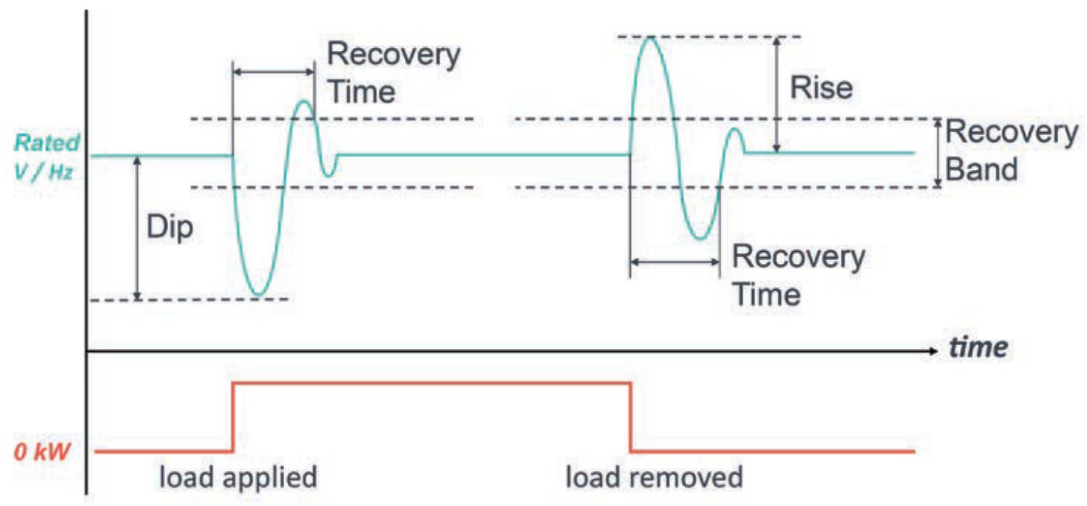
2.1. Industrial Requirements for the Transient Performance of Marine Gas Engines

In order to ensure the reliability and safety of power system operation, specific limitations on the dynamic performance have been outlined. The transient performance of the marine power system is often described as the system’s ability to follow the instantaneous increase or decrease loads caused by environmental conditions. Taking into account two types of applications of onboard gas engines, as shown in Figure 2, transient performance is characterized by the dynamic behaviors of engine speed in the directly driven application and grid frequency and voltage in the generation application [45,53]. When the gas engine serves as the primary mover to drive the propeller directly, power is transmitted through the shafts and gearboxes. The main engine must follow the transient load demands. In systems coupled with a fixed-pitch propeller, the gas engine is controlled to operate through its rated propeller curve. Therefore, the engine speed is dominated by the propeller speed and is adjusted by speed governors. In this case, engine power shows the cubic relation of the speed. Following the typical load operation limits ranging from 25 to 110%, the engine speed is permitted to work within 103% of the rated speed [54]. The transient speed change rate cannot exceed 10% at any time while keeping the recovery time within 5 s [55]. The above limits are obtained from the requirements for the general guidance developed for diesel engines due to the lack of particular descriptions for gas engines. For the gas engines to work as the prime movers in gensets, they are used to drive synchronous generators to produce electric power to grids, and the grid frequency is determined by the engine speed [56]. In real ships, most gensets work in parallel at a constant speed to maintain a steady frequency to drive the frequency converters and propulsion motors. The loads from the propeller can be isolated softly by the power grids, reducing the direct influence on the engine states. Thus, the influences of converters controlling behavior and grid response are necessarily considered, and their fast response can provide more benefits. At the same time, the implementation of condition-dependent renewable energies leads to an increasing demand for the system’s fast response and precise control.
Detailed requirements for the dynamic performance of gas engines in genset applications and their classifications can be found in ISO 8528 [58]. Taking a loading operation as an example, when a sudden load is applied to the genset, there is a sudden increased demand for current from the exiting gensets, resulting in a drop both in voltage and frequency. Then, gas engines are required to recover the voltage and frequency to the rated values as quickly as possible. Similar behavior can be observed in the case of removing loads from the gensets. Due to this, the variation in both voltage and frequency, described as dip/rise, and the time required to recover them within the specific region, as described by the recovery time, are defined to qualitatively represent the above processes, as shown in Figure 3.
In consideration of various requirements for engine transition performance across different applications, four classes from G1 to G4 have been defined to categorize the levels of engine performance. These classes delineate the distinct requirements for frequency droops and recovery speeds, as presented in [58]. Additionally, load acceptance provides the operation limits for sudden load changes, which should be factored into engine control and power management. Reference [55] gives standard requirements for engine transient speed variation. It defines that this variation should not exceed 5% at steady state and should not exceed 10% during the transient states for electric propulsion ships. All of the above requirements bring additional challenges to the gas engine that have to be addressed by advanced technologies.

2.2. Dynamic Performance for Various Types of Gas Engines

Currently, gas-fueled engines are categorized into several types based on their fuel supply methods, each representing distinct fuel–air mixing and combustion processes [60], as shown in Figure 4. These differences in both physical and thermodynamic characteristics lead to diverse load response capabilities for gas engines. Generally, when the gas engine works in a loading condition, the engine speed controller gives the command to feed more gas fuel to increase engine power. However, precise control of the fuel amount can be challenging. During this transient action, sufficient air is not able to be supplied due to the delay in turbocharger speed, resulting in an extremely lean air–fuel ratio and the risk of knocking. A similar behavior can be observed during the engine unloading operation, leading to an extremely rich air–fuel ratio and the risk of misfire [61,62].
The direct injection type is mainly used in high-pressure gas–diesel dual-fuel engines (HPDF) and low-pressure gas–diesel dual-fuel engines (LPDF). In the case of HPDF engines, they work in the DIESEL cycle combustion, which is the same as conventional diesel engines. Their high-pressure fuel injection can be directly and quickly controlled, eradicating the risk of knocking and resulting in a transient performance equivalent to that of diesel engines [63,64]. On the other hand, LPDF gas engines operate in the OTTO cycle combustion and exhibit weaker transient performance than HPDF engines. However, according to the engine start-up and shutdown strategies, the fuel-switching operation must be performed during running, resulting in the risks of attenuating the engine’s transient performance [65].
Port injection type is a method of premixed fuel supply where gas fuel is injected into the intake manifolds using single or multiple injectors. These lean-burn spark ignition (LBSI) engines provide a nearly well premixed mixture of fuel and air and work in the OTTO cycle combustion. The fuel gas varies with the fluctuations of engine load, while the air amount remains the same, leading to the temporarily extreme air–fuel ratios. The knock and misfire limits determine a smaller working range than diesel engines, representing a weaker load acceptance ability. Figure 5 shows the similar transient performance of diesel and port injection gas engines at low loads but a weaker response of port injection gas engines at high loads.
The mixture-charged type is another method of using a premixed fuel supply to achieve LBSI combustion. Fuel and air are thoroughly mixed upstream, and a throttle controls the gas engine power. The time required to establish a stable pressure difference before and after the throttle indicates the transient performance of this kind of engine. A trade-off between efficiency and engine transient performance is evident, particularly given the high boost pressure in this kind of engine.
In addition to the influence of fuel supply type on the engine’s transient performance, another possible factor is the gas quality fluctuation. As mentioned in [66,67], considering the knock limit of gas engines, the implementation of gas fuel with higher resistance to knocking combustion is able to extend the working region and improve the engine’s transient performance.
In general, direct and port injection gas engines have better transient performance than mixture-charged gas engines. High-pressure direct injection dual fuel engines exhibit the best transient performance with a similar part load response to diesel engines, as summarized in Table 1. However, with the development of gas engine efficiency, achieving a better load response becomes more challenging for modern gas engines, especially the engines with high brake mean effective pressure (BMEP), high Miller timing, and increased air-boosting pressure due to limitations imposed by knocking.

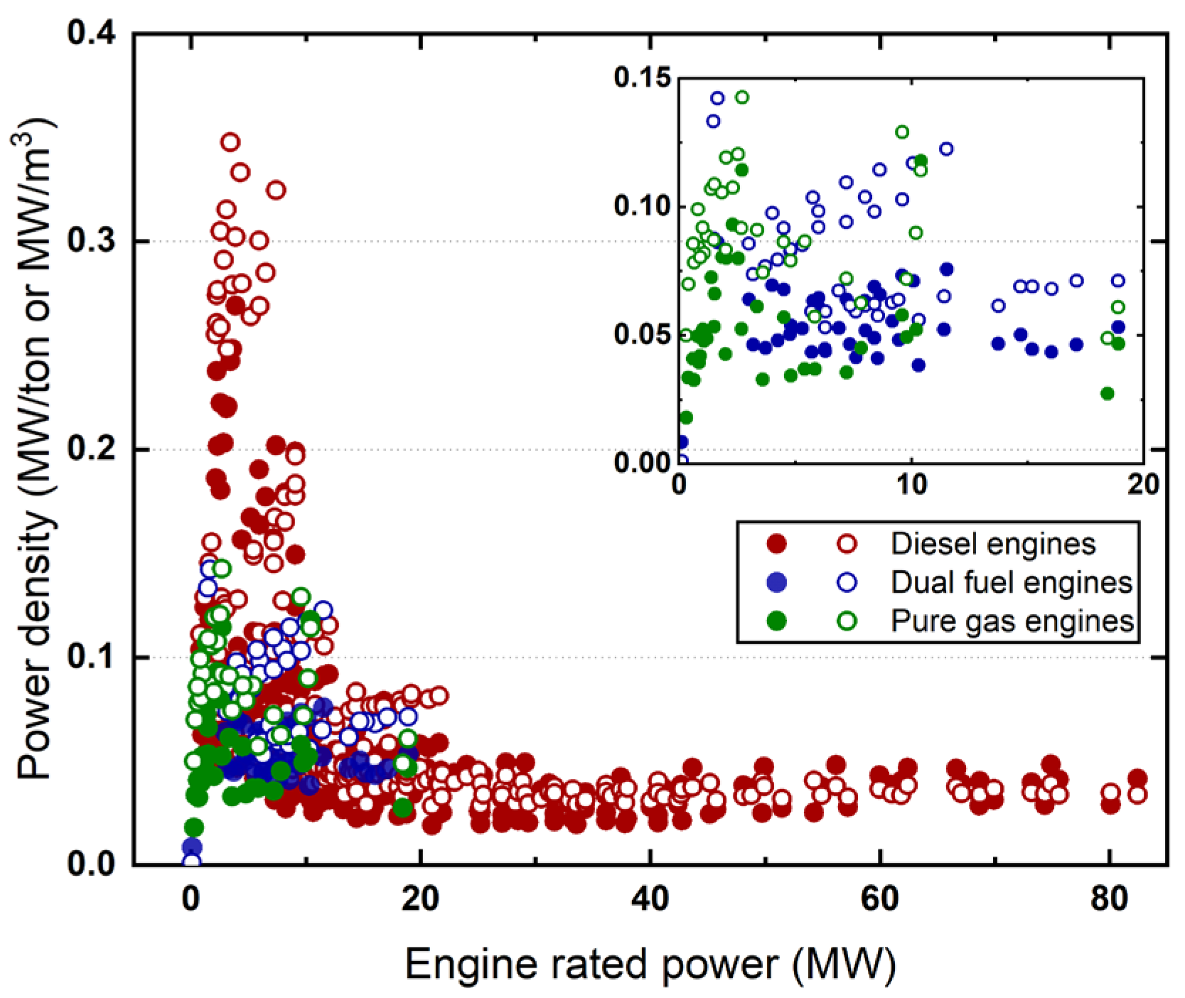
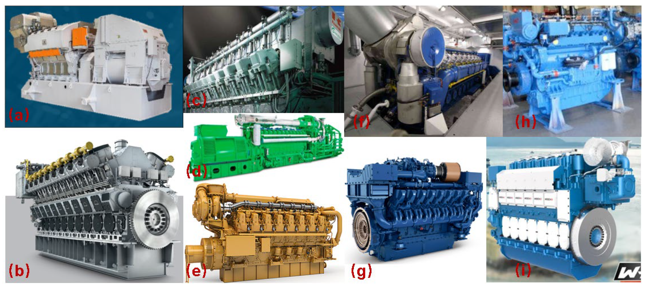
2.3. Available Gas Engines in Marine Applications

When applying gas engines on ships, the most important motivation is their potential to achieve decarbonization, which is a critical factor in dominating the feasibility of future transportation. Gas engines have been introduced to marine applications, encompassing both pure gas LBSI engines and dual-fuel engines. Considering the use of diesel as the pilot fuel in dual-fuel engines, a greater potential for decarbonization can be obtained from the LBSI pure gas engines in theory. However, apart from the carbon reduction achieved by using clean fuels, it is essential to consider the equivalent carbon emission caused by the methane slip in LBSI and LPDF engines. As a result, HPDF engines have demonstrated relatively better carbon reduction performance compared to other engine types, as compared in [53,69], and all the gas engines still exhibit lower emissions than diesel engines. Consequently, gas engines have been adopted in shipping fleets in recent years. Among them, combined with the considerations of fuel flexibility and load response, LPDF engines are the most widely used on LNG ships, with a market share of 78.1%. The least used are the LBSI engines, with a market share of 1.7%, as illustrated in Figure 6.
Another factor limiting the implementation of gas engines is the power density. From the investigation as shown in Figure 7, commercial gas engines show lower values in both engine rated power and the power density in mass and volume. Compared to diesel engines with maximum power densities of 0.35 MW/m3 and 0.27 MW/ton, LBSI pure gas engines and dual-fuel engines have the significant lower maximum power densities of 0.145 MW/m3 and 0.12 MW/ton. Regarding the engine’s rated power, the maximum four-stroke gas engine reaches the power of 19 MW obtained from the Wartsila 50SG [71], and the maximum two-stroke dual-fuel gas (LPDF-type) engine power reaches 63 MW from a WinGD X92DF-2.0 engine [72]. In comparison, the diesel engine power can reach more than 80 MW. Reference [53] has summarized the rated power regions of existing gas engines:
  • LBSI engine, medium–high speed (0.5–8 MW);
  • LPDF engine, four-stroke medium speed (1–18 MW);
  • LPDF engine, two-stroke low speed (5–63 MW);
  • HPDF engine, two-stroke low speed (>2.5 MW).
Figure 7. Power density information of current gas engine commercial products (the solid dots indicate the power density in mass (MW/ton), and the hollow dots indicate the power density in volume (MW/m3). The subfigure shows the power density of DF&LBSI engines within 0–20 MW. Data are obtained from MAN, Wartsila, MTU, CAT, and JENBACHER [73,74,75,76,77].
Jmse 11 02321 g007
Figure 8 provides detailed information about pure gas LBSI engines for ships. The commercial pure gas engines mainly include the Wartsila 31/34/50SG, MAN 51/60 35/44G, Kawasaki KG series, and JENBACHER INNIO J Type mainly used for generation applications and the Bergen B/C series, MTU IRONMEN, HECHAI CHG620L6MPI [78], WEICHAI WP series [79] for ship propulsion. Except for these engines, Hanshin [80] issued the low-speed LPDF gas engines, G25 and G30; they can be coupled to a propeller without the gearbox, and their maximum rated power reaches nearly 1.5 MW. It is worth noting that most pure gas engines with large-rated power function as the prime movers in power generation, while other pure gas engines with smaller rated power are used to drive the propeller directly. Since gas-engine response ability is influenced by the engine size [59], larger LBSI gas engines always show weaker transient performance than small engines, requiring a working scenario with fewer load fluctuations in generation mode. The data collected above demonstrate that the implementation of pure gas engines is limited by their low power density and weak load response, indicating the necessity to enhance the transient performance of gas engines by using optimal design and control methods through modeling and experimental studies.

3. Advanced Methods to Enhance Transient Performance

Along the pathway to green shipping transportation, challenges to improve the feasibility of gas engines on ships during steady and transient conditions must be addressed and requirements for the gas engine’s long-term emissions and short-term load response have to be met by innovative research. The majority of current studies focus on thermal efficiency and methane slip problems in steady states [81]. In sea conditions, time-varying loads have to be considered due to the fact that a decrease in the energy efficiency has been obtained at the part loads of gas engines [82], and the increase in emissions has been observed when gas engines work at wave load conditions [83,84]. To further reduce the emissions from gas engines, especially the methane slip, several methods have been proposed and examined [85,86,87]. However, these modifications may also affect the engine’s transient behaviors, indicating the necessity for collaborative design with the aims of both reducing methane slip and improving transient performance, as conducted in [87]. Considering some possible ways resulting in the methane slip, the improvements in the valve system, crevice combustion chamber volume, air–fuel mixture, low-load control, and fuel injection strategy have been considered by HD Hyundai Heavy [88], INNIO Jenbacher [89], and MAN [90]. Another series of studies are extending the working regions limited by knocking and misfiring in lean-burn engines, which are beneficial to enhance the transient performance. Jan et al. [91] investigated the influence of total and local air–fuel ratios in the pre-chamber on the engine misfire boundary to address this issue when using high-inert-content flare gases as fuel. Other solutions for speeding up the burning rate and enhancing ignition behavior by pre-chamber jets also work for avoiding misfires [92].
Regarding enhancing the transient performance of gas engines, several related limits should be paid attention to, including engine inertia, combustion limits, turbocharger delay, and control strategies [93]. Fewer studies have been conducted on the gas engine transient behaviors compared to steady states. Enhanced transient performance of gas engines is necessary to overcome the issues of load and gas quality fluctuations caused by real conditions and future e-fuels for isolated generation. Research methodologies and insights are borrowed from earlier studies for diesel engines due to their shared phenomena. In contrast to the detailed normal combustion and flame behaviors in mechanism research, greater attention should be devoted to understanding abnormal phenomena in gas exchange, combustion, and power transfer processes. This includes investigating aspects such as load recovery and combustion boundaries. Even though diesel engines have better transient performance than gas engines, there remains a gap in the engine load dynamic under real sea conditions, and related studies are valuable to give a reference to further studies on gas engines. In theory, engine transient performance could be improved by a lower compressed ratio, lower loads, and a changed air–fuel ratio, but it imposes adverse effects on energy efficiency and emissions [94]. Therefore, considering the reasons for the weak load response of combustion engines, associated studies have been carried out focusing on the air path system and load control methods to improve the engine’s dynamic response in both propulsion and generation modes.

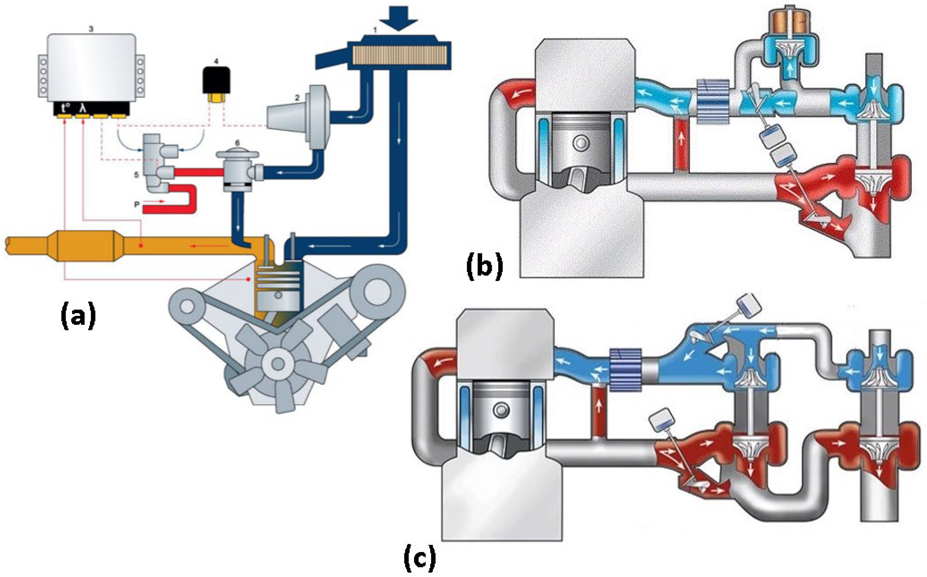
3.1. Air Path System Development

The objective of optimizing the air path system in engines is to provide adequate air rapidly by employing suitable air supply methods to follow the transient load points during the voyage. This approach stands for a general pathway to enhance the control accuracy of the air–fuel ratio and to improve the load response of the combustion engine itself, making it applicable to both diesel and gas engines for fixed and variable speed applications. However, as studied in [95], the real sea conditions with high-frequency fluctuations cannot be followed when using only an air throttle in gas engines due to its angle delay. Consequently, more measures have been investigated and discussed to increase the air supply ability in engines, especially for the turbocharger system, and their control strategies [94].
From the perspective of the turbocharger structure, the goal of these studies is to increase boost pressure and air mass flow during the running. Before developing advanced turbochargers to increase air-boosting ability, it should be noted that the reason leading to the time delay is the rotational inertia of the turbine and compressor, as discussed in [96,97]. The mass of the turbocharger determines the rotational inertia and the ability to prevent speed variation during varying loads and reduce the transient performance of engines. Consequently, lightweight turbochargers have been presented to reduce the response time to reach the required speed to feed sufficient air and to achieve smoother air pressure, as described in [97]. Another pathway is to enlarge the air-boosting pressure to match the mass flow. In this way, available measures include the assistant air supply equipment, two-stage turbocharger, variable geometry turbocharger (VGT), electric turbocharger, and valve control management (VCM). Among these, the assistant air supply equipment and electric turbocharger are the direct supply methods, and air can be provided with the active control signals as the additional devices to replenish the MAP of exiting turbochargers, providing flexibility on the working mass flow. In contrast, the two-stage turbocharger is driven in the same way as a conventional turbocharger, and its speed and mass flow are dominated by the energy exhaust gas thermostats. A special option is the VGT, which allows the flexible adjustment of the air mass flow by controlling the flow area. This enables precise control of the air–fuel ratio to avoid knocking and misfiring during the transient operations and exhibits the wide acceptance of various fuel gas compositions and qualities [98].
As mentioned before, modern gas engines require high-pressure boosting with the increase in the engine power density. Advanced turbochargers have been designed and examined due to the limitation of conventional single-stage turbochargers with a maximum pressure ratio of less than 7 [99]. The two-stage design of the engine turbocharger allows a higher pressure ratio and a larger air mass flow, as reported in [100]. ABB has proposed a two-stage turbocharger for large four-stroke gas engines to meet the requirements of extreme Miller cycle and high-boosting in the new lean-burn applications when the air mass flow can be enlarged by up to 1.3 times. The pressure ratio of the turbocharger can be increased significantly by up to 12 with a high efficiency of over 80%, as shown in Figure 9. Similar results have been observed in [101,102] to confirm the applicability of using a two-stage turbocharger to enhance the gas engine’s transient performance by providing sufficient airflow. Considering that the turbine speed and airflow are driven by the engine exhaust gas, it is hard to adjust the transient states of turbochargers. Therefore, an easier way is to supply the air with the electric turbocharger (ETC). The air mass can be adjusted untrammeled freely by the signals. Such electric turbochargers can be equipped to replace the conventional turbocharger or to couple with it as the assignment way. Most of them service with the conventional turbocharger as the ‘hybrid boosting’ concept, as discussed in [103]. Their effects on the faster load response and improved transient performance have been demonstrated in [104,105,106,107]. An electric turbocharger-based energy management strategy also has been designed in [108] for achieving optimal air system control and has obtained better tracking to the setpoints.
Another way to improve air mass flow is secondary air injection (SAI). As the most straightforward and simplified method to improve the engine’s transient performance, air directly injected into the intake manifolds is adopted in several applications. Additional high-pressure air can be provided during the engine scavenging operations, especially at the low load when the turbocharger has difficulty delivering the required mass flows. Garrett [109] has tested and compared the influence of direct air injection and electric turbochargers on an engine’s transient response and obtained similar results for these methods, resulting in a faster response than the baseline turbocharger. Norbert et al. [110] compared the transient performances of a gas engine boosted by a pressure-wave supercharger and a conventional single-stage turbocharger. The response time is 2.5 times faster when using the pressure-wave supercharger due to its high boosting ability under low engine speed. A faster response of the air injection method has also been confirmed in [111,112]. Their results show that the exhaust gas recirculation (EGR) increases the engine response time, and high-pressure gas assistance provides the fastest response compared with other methods, demonstrating the feasibility of this method.
Figure 9. A two-stage turbocharger MAP from ABB [113].
Jmse 11 02321 g009
To prevent the knocking and misfire limits during the varying-load operation of gas engines, controlling the transient air–fuel ratio is essential to these combustion limits and the engine’s transient performance. VGT and VCM technologies provide the ability to control the air intake mass accurately through the engine loads, as shown in Figure 10. VGT technology makes the nozzle vanes adjustable to optimize the flow area and, therefore, the mass flow at every engine load point so that the air mass and air–fuel ratio can be well matched to engine loads and ambient conditions to avoid misfire and knocking, as proven in [114,115]. With the advanced control method, VGT shows a more considerable potential to control the engine working states. Leng et al. [116] proposed a universal sliding-mode controller for the transient control problem during the fuel switching of dual-fuel engines with the VGT-EGR and throttle. They obtained smoother air pressure and, consequently, a better transient performance. Advanced control management on valves allows flexible air mass flow by the varying the timing under various engine loads. This method contributes to the better tracing of the transient loads and provides larger power redundancy at low speeds. As reported by ABB [117], VCM enables engine power to be changed by 50% within fractions of a second, which could reduce the need for controllable-pitch propellers with a faster engine response. Simulation work has been carried out for using the ABB VCM on a premixed gas engine with a Miller cycle, and the result shows higher load acceptance compared to the conventional throttle control [118]. Meanwhile, Jan et al. [119] applied the above ABB VCM system on a multiple-cylinder gas engine to increase the maximum engine load step by up to 15–20%, and the engine ramping time from idle to full load was reduced by up to 50%. However, the implementation of the high-pressure air assistant and electric turbocharger consumed additional energy, leading to a reduction in fuel efficiency, as mentioned in [120]. As a result, they designed the integrated system to drive the electric turbocharger by the shaft generator in the conventional turbocharger and obtained a reduction in fuel consumption by up to 2–3%. For further studies on the precise control of the air–fuel ratio, collaborative control of the multiple air-path systems is necessary for faster and more robustness adjustments under various conditions, as discussed in [121,122]. Advanced controls such as the model-based method and data-based method are required to be coupled with the developing turbochargers [123,124,125].

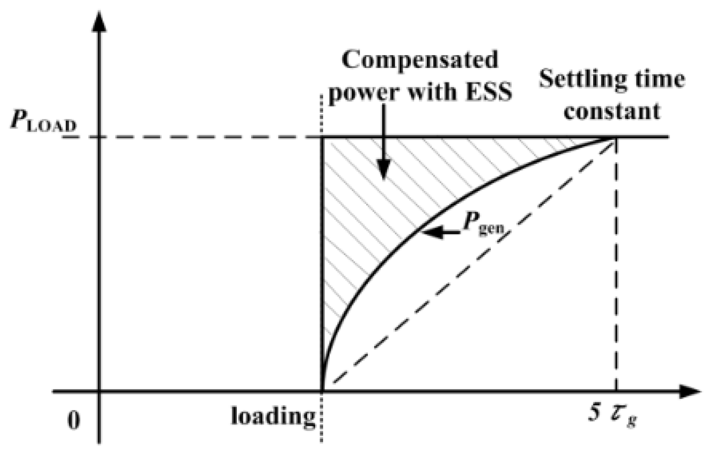
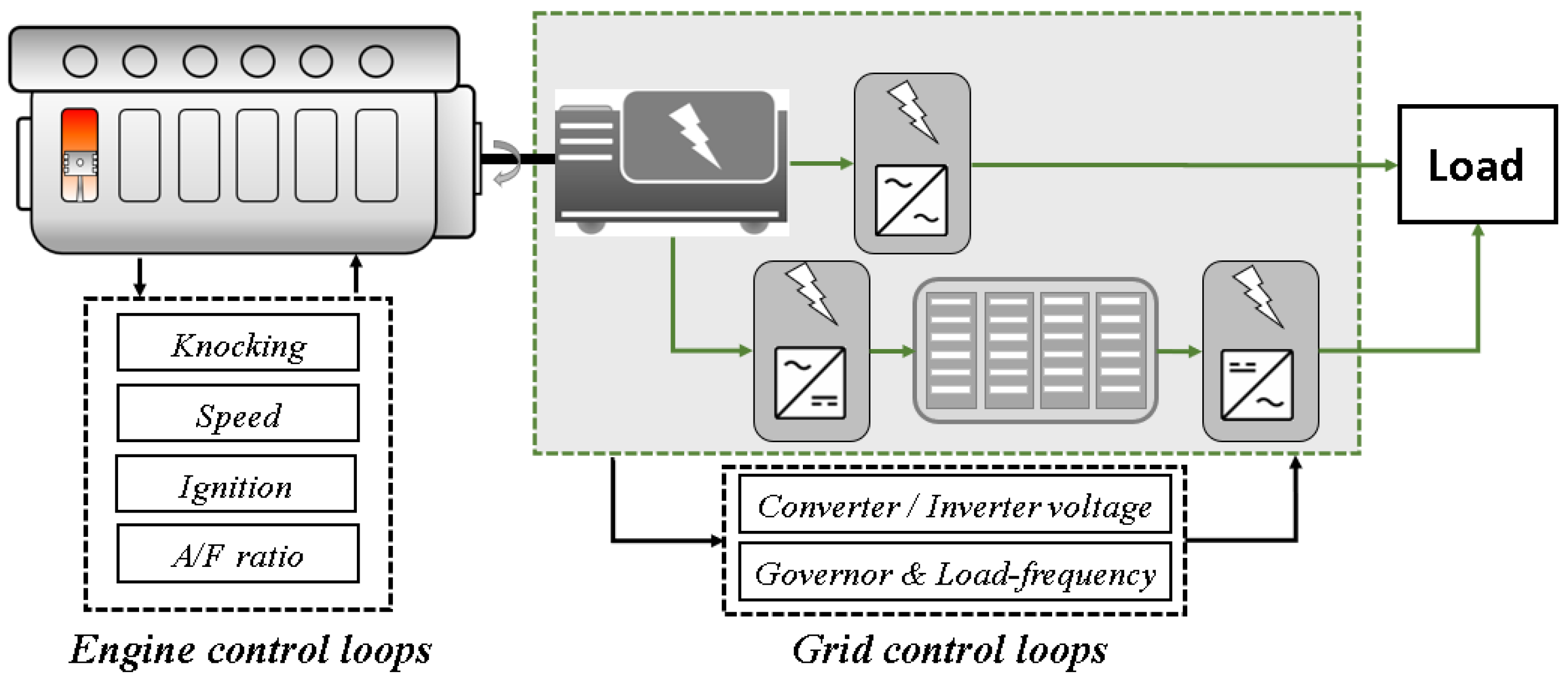
3.2. Power Management and Grid Control Development

The above developments on turbochargers and their control methods were conducted to provide the appropriate air mass following varying engine loads and fuel mass during transient operations. These studies set the engine load as the reference and target to be reached by controlling the air path. Better performance can be achieved when gas engines work at relatively steady states. Consequently, a feasible way is to control the engine load variation within a specific range during transient fluctuations to improve engine running stability and, therefore, the power system’s transient performance. Following this objective, engine loads have been optimized through advanced system power management and grid control methods.
For the gas engines to drive propellers in marine power systems, their load response determines the system transient performance due to the fixed speed ratio of the propeller to engines. Engine loads have been shared by implementing the hybrid concept and ESS to provide additional power during the voyage, as shown in Figure 11. The hybrid power system was employed for the initial purpose of energy efficiency of power systems equipped with diesel engines [129]. However, with the growing trend to introduce gas engines into the power system, their disadvantages in the load response have appeared and are of great importance. Meanwhile, ESS can be used to share the part load of gas engines to enable the relatively smooth transition of load, referred to as the gas–electric architecture. Thus, hybrid power, characterized by load splitting, benefits the improvement of the transient performance of the gas engine’s power systems. The implementation of the hybrid power system to assist ship propulsion and enlarge system reliability through load peak shafting has been confirmed in many studies based on the diesel engines and gas turbines on ships [130,131,132]. In contrast, less research has been conducted on marine gas–electric power systems. Moreover, they mainly focused on the steady states as discussed in [52,133]. Despite the main scope of reducing fuel consumption, a gas engine load trace with more minor fluctuations has been obtained by using a hybrid power design, as reported in [27]. Sun et al. [134] investigated the system’s transient behavior during the modes switching of a real gas engine, and the experiment result shows a shorter power system response time, demonstrating that dynamic compensation can be achieved by the hybrid concept. Xu et al. [135] established the marine gas–electric hybrid power system to optimize the system load response during the acceleration and modes switching by simulation study. The motor can be used for power compensation in engine low-load areas to improve the dynamic performance of the power system.
The above studies demonstrated that the transient performance of gas engine power systems can be enhanced by splitting power fluctuations when configuring the hybrid power concepts and ESS. This method is suitable for both marine power systems equipped with gas engines that work for propulsion and generation. On this basis, advanced system energy management methods provide a larger potential for further developments and are required to trade off the transient performance and the system energy efficiency.
When the gas engines are equipped to drive propellers, the power system’s transient performance is eventually reflected in the engine combustion limits. Differing from that, when the gas engines serve as the prime movers in gensets, the power system’s transient performance dominates the power grid frequency and voltage stability during the transient operations in waves, which has been tested in [137]. In this mode, power splitting of ESS combined with an advanced energy management strategy (EMS) is also an effective solution for keeping the grids steady, as discussed in [138,139,140,141]. Between the power sources of gensets and the power consumption of the propulsion system, electric energy is converted and transferred by related components, which influence the power response of the whole grid. The control of such equipment is also essential to the power system transient performance and has been studied from the views of system inertia and direct control methods [142]. The transient stability of power grids can be influenced by the system inertia that represents the system’s resistance to prevent frequency variation. As a feasible solution, the virtual synchronous generator (VSG) technology has been developed to enlarge the system’s total inertia by introducing simulated rotating mass. By applying this control approach to the permanent magnet synchronous generators, smoother transition under the loading and unloading conditions can be observed in both islanding and grid operations [143]. However, it should be highlighted that the implementation of this control method necessitates detailed grid models, particularly the converter control models on both the generator side and load side [144].
In summary, two options aimed at enhancing the transient performance of marine power systems driven by gas engines have been presented and examined, mainly utilizing simulation methods in previous studies. These measures can be understood from both the gas engine level and the system level. It can be found that the improvements in gas engine air path systems and load controlling both benefit the power system’s transient performance, as shown in Table 2, and show larger potential when combined with the coordinated and advanced control strategies.

3.3. Study Gaps

After the aforementioned technical summary and literature review in Table 2, it can be seen that the presented studies to enhance the marine power system transient performance can be classified into two kinds of pathways. At the early stage, due to the broader applications of diesel engines, more studies have been conducted on developing their air path systems and related control methods. Considering the similar delay phenomenon, the same methods on the turbochargers have been applied on gas engines in recent years. Another pathway is the loading splitting by the ESS and grid control methods on the system management level. However, this approach is still relatively rare, and related research is not as common as the developments on the air path systems.
On the other hand, regarding the research method, these studies are mainly conducted by simulation method instead of experiments, especially the research on large-power marine engines and system-level developments. This indicates the difficulty of conducting the real engine, even the real ship experiments, which are limited by the physical sizes of existing test benches. At present, regular loading and unloading ramps are used to test the transient performance of power systems rather than real sea conditions. Unified test procedures are scarce due to the versatile and intricate scenarios at sea. Except for the pilot commercial engines from manufacturers, such gas engine test benches are still lacking, especially the large-bore gas engine. Single-cylinder engines have been developed for simplification and can be used for steady-state studies in laboratories [150,151,152]. They are primarily charged by the supercharger or compressors directly, rather than utilizing a real turbocharger due to the exhaust gas pulsation. Therefore, limited by the experimental conditions, most of the current transient studies are finished based on the simulation models that are still expected to dominate the later developments in the future.
The fidelity and precision of simulation models are of great importance for reproducing and investigating the transient performance of marine power systems. Accurate sub-models and controls for gas engines, power shafts, and propeller–hull dynamics in direct drive mode and the sub-models and controls for gas engines, generators, and power grid and propeller–hull dynamics are needed to align the simulation results with the experimental ones, and this often comes with high credibility but also high complexity. In balancing simulation precision and costs, considering the specific topic, current studies often involve significant simplification in one or more parts of the engine thermodynamics, the power grid electromagnetic transient, and the fluid dynamics of propeller–hull interaction mechanisms. This may lead to a distortion of the transient dynamics and their mechanistic details. Despite this, the combination of several simplified models still shows limited performance in achieving high simulation speed.
One challenging aspect of establishing full-scale models by combining the above detailed dynamics is the multi-time-scale interactions between the coupled physical–chemical behaviors. Concerning the factors affecting the system’s transient performance, sub-models, and their control systems for gas engines, power transitions and propulsion systems exhibit significant differences in time scales, impacting their response behaviors. Referring to the studies from [153], it is evident that at least three stages of time scales exist in general marine power systems: mechanical time scales related to the engine speed, shaft and propeller speeds at the 1 s level, a DC and control system time scale related to the ESS at the 0.1 s level, and an AC and control system time scale related to the generators and grids at the 0.1 s level, as shown in Figure 12. The coupling and influence of multiple time scales result in the complex transient performance of power systems, necessitating further in-depth investigations. Therefore, appropriate simplifications have to be conducted facing various control, optimization, and some energy management applications. For future applications of alternative gas fuels like hydrogen and ammonia, such considerations and studies were found to be budding.

4. Transient Modeling for Marine Power System

In terms of enhancing the transient performance of gas engine power systems on ships, modeling methods with high accuracy for various objectives are indispensable before performing the system-level simulations. Transient studies that focus on system load response mainly rely on physical-based simulation models. To comprehend the overall transient response behaviors, it is essential to consider all the key components that impact the system response. A typical gas-engine-based marine power system comprises a gas engine system, propeller, shaft system, power grid, and ESS (only for generation mode), as shown in Figure 12. Gas engine models are developed employing cylinder thermodynamics modeling; transmission ratios and rotational dynamics organize shaft system models; propeller models are established using the simplified hull resistance and thrust power modeling. Among them, power grid and ESS models are constructed based on the energy balance and electric dynamic modeling. In line with the specific objectives, most studies used selected components of the models mentioned above to construct complete system models.

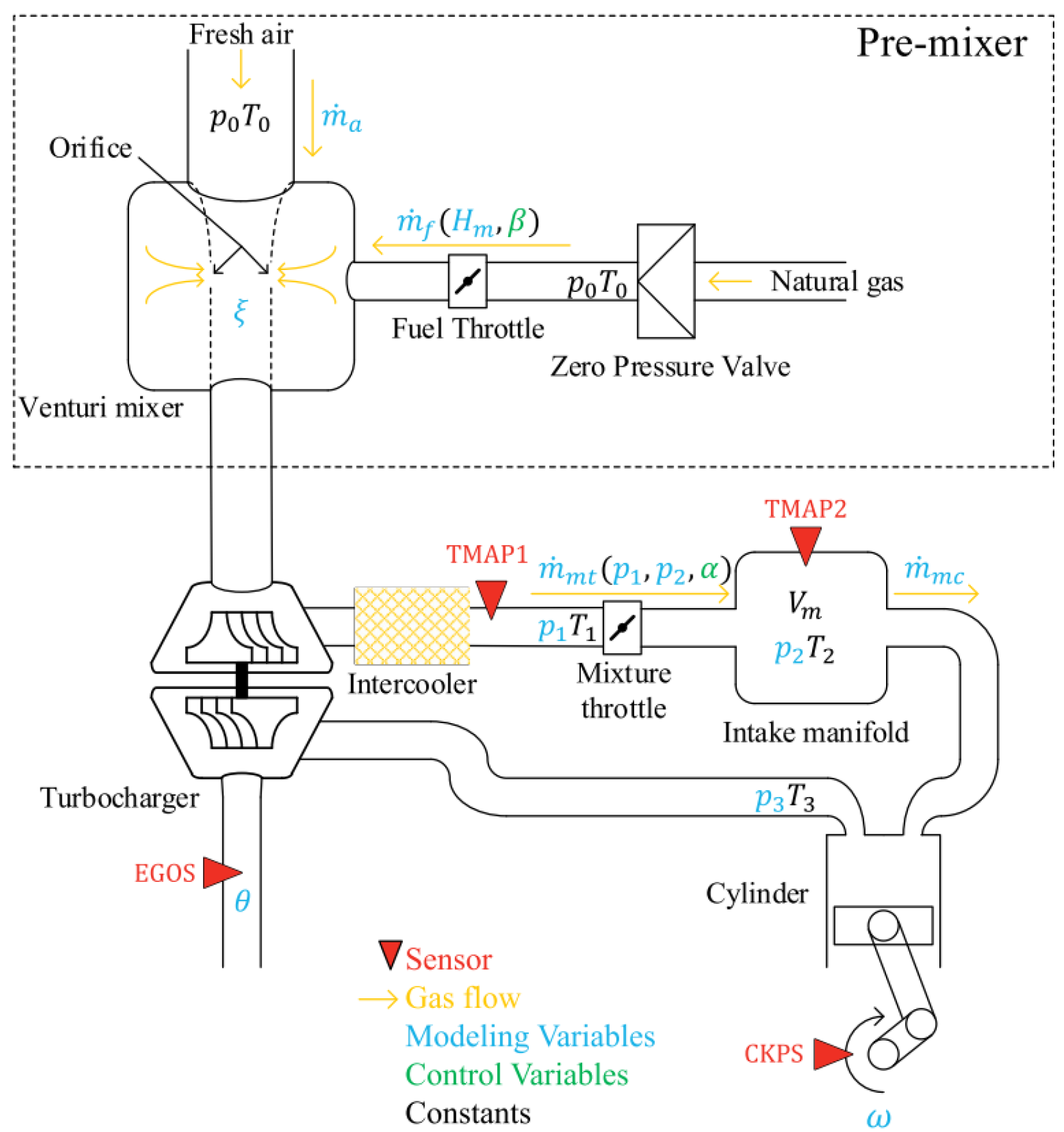
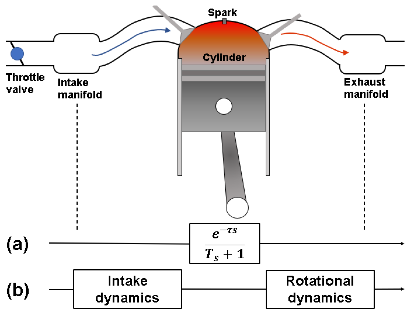
4.1. Gas Engine System

In a typical gas engine system consisting of intake, compression, combustion, and exhaust processes, torque and power are generated by the heat released from fuel combustion, and then, the thermal energy drives the movement of the piston. The speeds of the crankshaft and the engine are influenced by the forces acting on the piston and dominated by the mass of fuel gas and air in the cylinder. This mixture can be controlled during the engine running by adjusting the valve or injection timings. The description above emphasizes that the engine dynamics are governed by both the physical principles in terms of the gas–air flow, mixture, combustion chemistry, and mechanical dynamics of the piston, rod, and shaft, as described by Newton’s law and the first law of thermodynamics.
In detail, by tracking the flow path of the gas and the energy transmission, as shown in Figure 13, the entire process of the gas engine operation can be understood as the foundation for modeling. Taking a premixed gas engine as an example, the fresh air is boosted into the intake manifold by the turbocharger. It is adjusted by the throttle valve to maintain a predefined air–fuel ratio. Inside the intake manifold, the fuel gas is controlled to be injected through single or multiple injectors and mixed with fresh air. The mixture is further controlled by the intake valves to charge the cylinder and is then ignited by a spark or pre-chamber jet to initiate the combustion process. The combustion-induced heat release increases the cylinder pressure that is converted to the force on the piston head and drives the connection rod and crankshaft of the engine. After this, the combustion products are exhausted under the control of the exhaust valves, and some of this gas is used to drive the turbine fan of the turbocharger, while the rest is recycled in EGR and wastegate or discharged to the aftertreatment equipment. This process represents a general design for modern gas engines. In specific types, additional devices may be introduced to achieve better control of the compressor surge and air–fuel ratio. Following this procedure, models for simulating the gas engine’s transient performance can be established by assembling sub-models of the above major components in the system, as summarized in Table 3.
Before starting the modeling of gas engines, it is crucial to define the modeling level to match the study objectives and resources. The most detailed modeling approach is the three-dimensional (3D) computer fluid dynamics (CFD) simulation; it is dedicated to the local and detailed phenomena of turbulence, flame, and chemical kinetics and is not suitable for the transient performance due to the time costs. In contrast, the most simplified zero-dimensional (0D) method shows the fastest performance. However, it lacks the description ability for the complex dynamic behaviors of flow and chemical reactions in the cylinder; therefore, there are insufficient details to show the transient performance of combustion engines. Currently, for capturing the transient behaviors of the gas engines, one-dimensional (1D) modeling has been considered a feasible tool to reproduce the time-series engine variations. It has been widely applied in engine design, control, and optimization studies [115,155]. Based on the control volume method, the time-varying thermo-states of the gas mixture before ignition can be described by the ideal gas law, while the energy transfer during combustion can be represented by the mass conservation and first law of thermodynamics. Because of the complexity arising from the coupling of gas flow and combustion, the precise mathematical description is challenging to solve, leading to the need to simplify the flow and combustion states by some assumptions. When modeling the gas engine transient behaviors through the 1D simulation method, in addition to the combustion and rotation movements, the air supply dynamic is critical for the instantaneous fluctuations of the engine torque and speed. For major parts of the gas engine system, individual sub-models can be defined as follows.

4.1.1. Inlet and Exhaust Modeling

When modeling the intake and exhaust behaviors of the engines, the intake and exhaust manifolds are regarded as the control volume, and the thermodynamic states of the air can be modeled during the engine scavenging and exhausting operations. The pressure, density, and temperature dynamics of gas are described by the ideal gas law and mass conservation equation and can be given as follows:
P i m = T i m R i m V i m W t h r W c y l
P b m = T b m R b m V b m W c o m p W t h r W b y p
P e m = T e m R e m V e m W c y l W t u r b W w g
where P and W denote the pressure and gas mass flow rate, respectively. T, R, and V denote the temperature, mass-specific gas constant, and volume, respectively. The subscripts im, bm, em, thr, cyl, comp, byp, turb, and wg stand for intake manifold, compressor outlet manifold, exhaust manifold, throttle, cylinder, compressor, bypass, turbine, and wastegate, respectively.
According to the air paths between the air sources and the cylinder intake valve, as well as the airflow through the cylinder exhaust valve to the aftertreatment ports, the interfaces indicated by the above equations should be adjusted to match the real engine architectures. Specifically, the gas states before and after the throttle, bypass, wastegate, turbocharger inlet, and outlet also should be modeled by the specific equation, as given in [122].

4.1.2. Valve Flow Modeling

In real engines, many valves are assembled on the gas flow roads. They can be simplified as nozzles, and their effects on the gas mass flow can be expressed using the steady-states Bernoulli equation as the following formula [156]. The discharge coefficients depend on the flow area shape and need to be estimated and calibrated by the experimental data. The upstream and downstream pressures, as well as the gas temperature, can be provided by the related ideal gas law equation as mentioned above.
W = C D A P i n R T i n φ P o u t P i n
φ P o u t P i n = 2 γ γ 1 P o u t P i n 2 γ P o u t P i n γ + 1 γ P o u t P i n 2 γ + 1 γ + 1 γ 2 γ γ 1 γ + 1 γ 1 P o u t P i n < 2 γ + 1 γ + 1 γ
where CD and A denote the discharge coefficient and area of the nozzle, respectively. γ stands for the specific heat ratio.

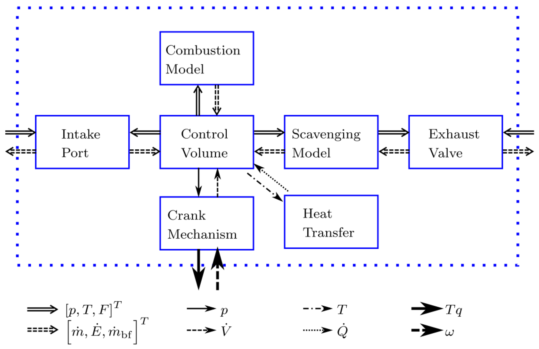
4.1.3. Engine Cylinder Modeling

The cylinder is the most important part of the engine modeling, which consists of mixture intake and heat release dynamics, as well as the heat loss variation, as shown in Figure 14.
Following the floating air mass flow, the instantaneous air–fuel ratio in the cylinder and the later combustion can be influenced. The mass flow of the fuel and gas mixture supplied to the cylinder from the intake manifold can be modeled using the speed density flow function. The volumetric efficiency and cylinder displacement volume are fixed for the specific engine, the intake pressure is provided from the above function, and the engine speed is provided at a constant value or can be obtained from the last time step.
The combustion process within the cylinder can be characterized by the burn rate, indicating the composition fraction of the burned and unburned gases along with the crank angle. Several combustion models have been developed for defining the burn rate during the engine running, including the Wiebe function-based nonpredictive models, which rely on the predefined baseline and on the predictive, as well as the semi-predictive models, by introducing the turbulence flame speed, mixing, and real physical considerations in single or two zones to predict the burn rate of the combustion process; more details can be found in [158]. At the same time, heat transfer during combustion also needs to be considered and is expressed mainly by the Woschni model as the function of the temperature difference and areas [54]. Despite the limitation of the predictability of the Wiebe model, it can be seen that it is widely applied in studies by ignoring the fluctuations in the burn rates during the varying transient conditions [159,160]. Heat release can be determined, and then, the cylinder pressure dynamic can be deduced based on the energy conservation law. For rapid control purposes, the combustion rate and heat release rate are often approximated by fitting experimental results, along with the air–fuel ratio, using simplified functions, as studied in [122,161].

4.1.4. Crankshaft Dynamic

The cylinder pressure during the cycle is transferred to the force acting on the piston and then the engine rotation. The force can be estimated by the piston diameter and the pressures in the combustion chamber and crankcase. The rotational motion of the crankshaft is driven through the connection rod with the cylinder displacement. Therefore, the crankshaft rotation is deduced by the balance of the load torque and generated torque, considering its inertia moment.

4.1.5. Turbocharger

As mentioned before, one of the main factors that dominate the gas engine’s transient performance is the gas exchange process. This is because the instantaneous air mass determines the air–fuel ratio of the mixture supplied to the cylinder. Accurate modeling of this process is critical for the whole gas engine model. As the source of the intake gas, the turbocharger dynamic should be modeled accurately to represent its time delay and real mass flow during the transients.
Predicative turbocharger models have been developed for the accurate simulation of efficiency [162], but the common method in transient scenarios is the implementation of the turbine and compressor MAPs to provide the pressure ratio, mass flow, and efficiency, as shown in Figure 15. As the discrete description, the look-up table is widely used while the polynomial function of the pressure ratio across the speed has also been applied as a continuous method, as used in [122]. It can be seen from the MAPs that the turbocharger speed determines the air mass flow, and its time delay dominates the engine response ability. Similar to the crankshaft rotation dynamic, the turbocharger speed dynamic can also be modeled based on Newton’s second law by introducing the inertia, whose effect on the engine load response has been proven in [96,97]. A summary of the physical-based modeling of the engine components is listed in Table 3.
Table 3. Physical-based modeling of the engine components [163].
ComponentsSub-ComponentsProcessSub-Model
CylinderControl volumeThermodynamic states0D single zone
Heat transferConvection and diffusion (Woschni)
Scavenge portMass flowIsentropic compressible fluid flow with discharge coefficient
Exhaust valveValve liftLook-up table
Mass flowIsentropic compressible fluid flow with discharge coefficient
CombustionHeat release rateWiebe or predictive model
ScavengingScavengingEmpirical model for exhaust gas composition
Crankshaft Energy transformationKinematics
TurbochargerCompressorMass flow, efficiencyLook-up table
CompressionIsentropic compression with efficiency
TurbineMass flow, efficiencyLook-up table
CompressionIsentropic compression with efficiency
ShaftSpeedShaft rotates kinematics
Scavenge air cooler Mass flowIsentropic compressible fluid with discharge coefficient flow
Heat transferEffectiveness-NTU method
Scavenge air & exhaust gas receiverControl volumeThermodynamic state0D single zone
Heat transferNo heat transfer
Wastegate Mass flowIsentropic compressible fluid with discharge coefficient flow
After enumerating the modeling methods of gas engine thermodynamics, the control methods of the engine speed and air–fuel ratio are given to maintain reliable engine working. For the commercial premixed pure gas engines, their speed and air–fuel ratio are controlled by the throttle valve or gas injection valve (port injection type), wastegate, and bypass for turbocharger by tracking the designed maps, as shown in Figure 16. Generally, the gas engine working states are controlled at the fixed speed mode for generation and propulsion applications. The control methods are executed by the proportional integral derivative (PID) controller, benefiting from its fast response, as implemented in [143,164,165]. For further development of the control speed and reduction in oscillation, advanced control methods on the engine speed and air–fuel ratio have been presented. Gong et al. [154] designed a hybrid model predictive control strategy for improving the control performance of the gas engine transients. This strategy was used for a hybrid model containing a first-order model for air–fuel ratio control and a second-order nonlinear model for speed control. Huo et al. [166] obtained better performance on speed control for an LPDF gas engine in the dual-fuel mode by using a model-based predictive control (MPC) method. They pointed out the limited tuning response of the PID control in some special conditions. However, they also demonstrated the faster nature of PID control than other methods. Otherwise, advanced control methods based on state estimation and feedback enable stability, self-convergence, and high accuracy [167]. It can also be seen from these studies that the gas engines have been reduced for the simulation speed consideration, and physical-based thermodynamics models were replaced by the simplified control-oriented models described by liner or nonlinear functions. The reason has been pointed out by [161]: physics-based models have the features of complicated mathematical representation with high dimension and strong nonlinearity, uncertainty, and probability. However, the development and validation of the advanced control strategies require steady models with sufficient fidelity to capture the control variables of the gas engine’s running, control, and optimization. Established models are required to maintain acceptable variations during the control robustness tests. Therefore, appropriate reductions in the physical-based gas engine models are needed to trade off the requirements on the model fidelity and simulation speeds according to related research purposes. The same considerations have also been taken for the following models of other parts in marine power systems, so the description and discussion of the model reduction will be provided in the subsequent chapter.

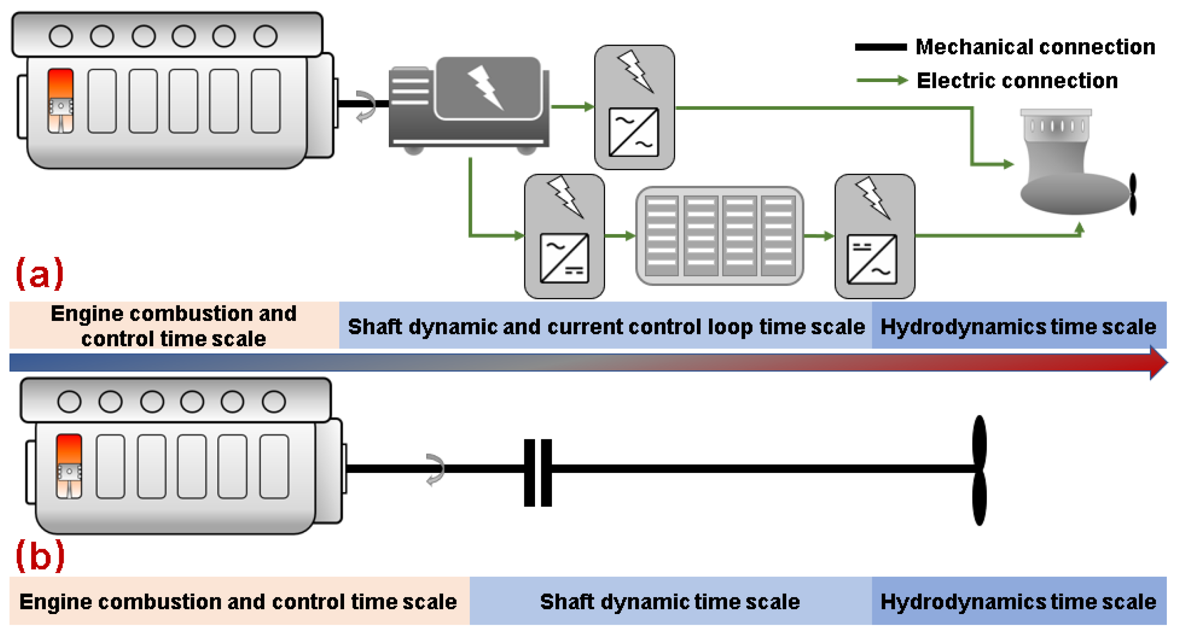
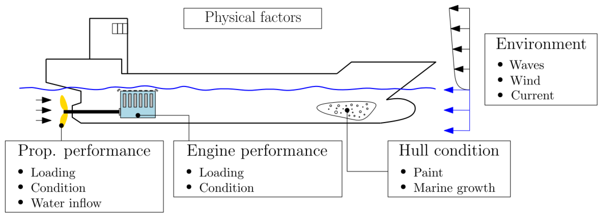
4.2. Propulsion Power and Hull Resistance

Marine power systems work in time-varying sea environments, which pose a requirement for their engine transient characteristics [169]. Essentially, the load acting on the ship propellers determines the propulsion power demands for the power system, which is the collaborative result of the wind and wave resistances, as well as the operation commands, as shown in Figure 17. When ships sail in real sea conditions, especially in harsh water, power system loads will exhibit significant variations, challenging the engine transient performance. To investigate the impact of the actual operating environment on the performance of the power system, modeling the ship environment and the hull–propeller interaction is critical for producing the real load conditions for power grids and gas engines. Simone et al. [170] compared the influence of the engine–propeller model accuracy on the engine speed and torque estimations, demonstrating the necessity of considering the propeller–engine dynamic in waves.
Considering the ship resistance induced by wind and water, the hydrodynamic estimation method should be introduced. Establishing such models needs the understanding of the torque transmission through the propeller to the engine shafts; before that, the load torque on the propeller is generated by the water flow and wind resistance. The wind resistance on the hull can be estimated by means of the wind area of the ship structure above the water, as proposed by Blendermann [172] and Fujiwara [173], by calculating the longitudinal and lateral wind forces and yaw and heel moments for ships. Detailed procedures can be found in [174,175]. For water resistance, full-scale hydrodynamic models have been developed but lack the rapid applicability for the power-system-level simulation. Therefore, several fitted models obtained from the model tests are suitable for computing the added resistance on ships in regular and irregular waves. In regular waves, the added resistance can be calculated by the DTU in-house method [176], while the ITTC [177] method can estimate the added resistance in irregular waves. Many other methods based on the towing tank tests have been proposed, providing related correction coefficients for various types of ships in STA1, STA2 [178], NTUA-SDL2 [179], and SNNM [180], as reported in [181]. Such simple models only require the ship’s overall parameters and voyage speeds, providing fast calculations for the design and simple estimations. At the same time, due to the lack of a unified test procedure and standard, the environmental conditions can be referenced from databases measured from real data in previous years, such as ECMWF ERA5 [182] and JONSWAP [183], or the designed wave spectra by the wavelength, amplitude, and direction, as conducted in [44,184]. After the estimation of the weather resistances on the hull, the propeller torque demand can be obtained by Newton’s second law. For another, the propeller torque and thrust can be estimated by the non-dimensional coefficients KT and KQ, as well as by the propulsion factors for specific types of propeller as the function of speed [185,186]. This method is always adopted in the control-oriented power system and the collaborative analysis coupling with combustion engines [187] due to its balance of the simulation speed and transients-capturing ability [188,189,190], which can be expressed as below:
F T = K T ρ S W n 2 D 4
M p r o p = K Q ρ S W n 2 D 5
where FT and Mprop stand for the thrust force and torque from the propeller, respectively. KT and KQ represent the coefficients of thrust and torque, respectively. ρSW stands for the sea water density; n and D represent the propeller speed and diameter, respectively.
For gas engines directly coupled with the propeller, their speed is determined by the propeller through a fixed ratio. In this case, the fluctuations in the environmental conditions lead to variations of engine torque and speed simultaneously. In another application, when gas engines work as the prime movers for generation, their speed can be decoupled from the propeller, showing better natural anti-interference to the transient sea conditions.
The previously mentioned methods introduce the detailed modeling of the wind and wave loads on the propeller. Despite the models being simplified for variable interfaces, their detailed requirements on the ship parameters and sea conditions still impede their fast implementation in transient applications. As a result, a more straightforward approach has been adopted through the fitting formula according to the real power traces from the sea trails, as presented in [191]. This method allows the estimating of the propulsion power as the function of ship speed but only works for ships with the same types. At the same time, in some studies, the above procedures have been replaced by setting a fixed sea margin of 5–15% [181], but it is challenging to reproduce the transient effects of sea conditions.
P t = P r e f D t D r e f 2 / 3 V t V r e f n η w η f
where P, D, and V denote the ship propulsion power, draught, and speed, respectively. Subscripts ref and t represent the referred design and target ships, respectively. ηw and ηf stand for the coefficients of hull resistance and water conditions, respectively.

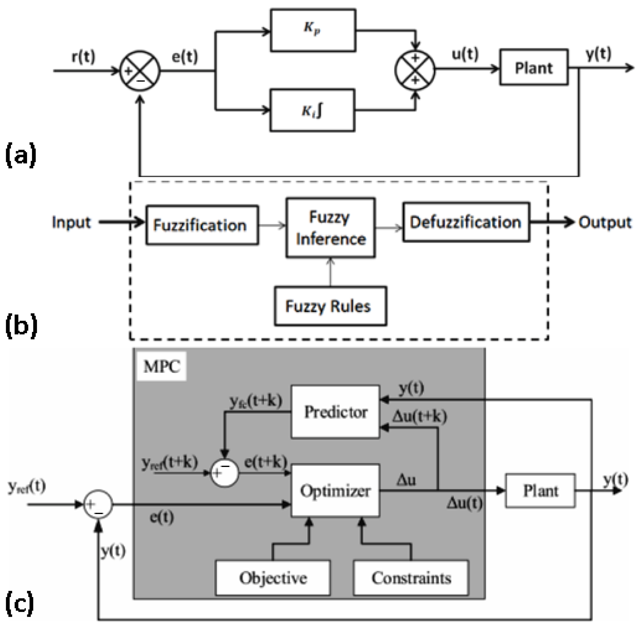
4.3. Power Grid Control and System Energy Management

With the growing trends of ship electrification and power system hybridization, onboard power grids and ESS are playing more crucial roles in the system’s transient response. Implementation of electric equipment introduces additional load delays to the power system, especially in the scenario that the ship is driven by electric motors in the pods while the gas engines work as prime movers. In addition to the improvement of the gas engine itself, which plays a significant role in power transmission from the gas engine to the propeller, the improvement of the control methods of the power grids benefits the load control of the gas engines. It offers a feasible way to enhance the system’s transient performance. Considering the model complexity during simulation, inverters and converters receive more attention, and their control methods are investigated to manage the system transient behaviors [192]. As a result, the typical framework of the gas engine generation system includes the gas engine as the prime mover, generators driven by gas engines, inverters, converters, and loads. In a hybrid power system, ESS is included in the framework in parallel, as shown in Figure 18. From a control perspective, to ensure the functions of the power system, the gas engine’s air–fuel ratio and ignition can be controlled to maintain the engine speed and prevent abnormal knocking phenomena. The power grid frequency is regulated by controlling the system current and voltage using inverters and converters during operation. When ESS is adopted in the power grid, a DC link containing the related AC–DC–AC converter must be configured.
In general, for an AC bus marine power grid, the AC–DC–AC conversion is typically accomplished using a diode rectifier. However, in this setup, only the load side of the rectifier can be controlled, while the generator side rectifier remains uncontrollable. This may lead to torque fluctuations during the transient operations [193]. Consequently, a new kind of rectifier that allows control on both sides has been proposed by replacing the diode with the insulated gate bipolar transistors (IGBTs) to reduce the current and voltage variations, as well as the grid frequency, as shown in Figure 19. Building upon this development, advanced control methods have been introduced to increase the system inertia by the load side rectifier VSG control and the generator side voltage control. In VSG control, a typical swing equation of the synchronous generator is simulated by the virtual swing equation, providing the virtual inertia of the generator to the power grids, and the system inertia and the transient performance have been enhanced [144]. It is worth noting that in such applications, similar to the engine control method mentioned above, traditional PI controllers and transfer function time delays of the regulators are implemented. Similar modeling and control methods have also been applied in [164,194].
When applying ESS to the power grids, the benefits of engine load control can be obtained, and the flexibility of energy management can be increased. As mentioned earlier, due to the power splitting of the ESS, the power demand on the gas engine can be smoothed, resulting in a better engine load point with a higher response. Consequently, the power system’s transient performance can be enhanced. Related simulation results and evidence are described in Section 3.2. For transient performance prediction, ESS models that can capture the dynamic current and voltage are required to be coupled with the power grid parts. Unlike the electrochemical models in many studies that represent the chemical–thermal processes of the ESS during the simulation [195], a more detailed description of the ESS state of charge (SOC) that consists of the real system current and voltage can be expressed using the Rint model function [196,197]:
E E S S = V E S S I E S S R S
S O C t = S O C 0 0 t I E S S d t C E S S
where E, V, I, and R stand for the battery energy capacity, voltage, current, and resistance, respectively. C represents the discharge coefficient of the battery.
In addition to the gas engine control and grid frequency control, the system EMS for making the multiple power sources such as gas engines and ESS collaborate during various voyage scenarios also garners significant attention. As summarized in [198], alongside EMS studies that concentrated on emission and fuel consumption reduction, much research focused on the power grid stability, which also means the grid’s transient response. Similar to previous studies, in gas–electric power systems, the primary objectives of EMS include reducing gas engine speed and grid frequency variations, as well as minimizing system emissions and fuel consumption. EMS determines the power distribution between gas engines and ESS and provides loading and unloading ramps for the engines. To manage the start-up and shutdown states and control the power outputs of the gas engines and ESS, EMS needs to be optimized to provide appropriate commands in real time. Before this, the selection and sizing of gas engine power and ESS capacity should be considered because their load response characteristics are impacted by physical sizes. The ESS response is limited by the discharge rate, which is the ratio of the maximum transient power to the total energy capacity. The gas engine response is limited by mechanical inertia, as discussed before. Typically, larger gas engines exhibit slower load response.
Consequently, addressing these issues of the current marine power grids and sizing of the ESS and the EMS are the main topics associated with the system load response. De Siqueira et al. [199] conducted an ESS capacity-optimization study to reduce power fluctuations. For fast application, traditional rule-based EMS shows the natural advantage of the simulation speed and was widely used for real engineering development and the verification of the model accuracy [192,195]. However, the rule-based EMS is insufficient for controlling the complex power system with nonlinear and random variations.
Consequently, advanced-control EMS combined with the collaborative control of multiple power sources is necessary to improve the system stability further. Pan et al. [196] established a coordination EMS based on power differences for power grids. It can be seen that the transient performance of the DC bus voltage can be improved. Hu et al. [200] proposed a real-time MPC-based EMS for all-electric ships by introducing the battery and ultra-capacitor ESS. The test results show that the bus voltage variation can be reduced by up to 38%. For further control of the power distribution, based on PID control, the fuzzy control [201] and MPC control methods have been developed for reducing the power variations, as shown in Figure 20. The data-based deep learning methods provide a larger potential to overcome this problem for further studies [199].
While many advanced studies of EMS have been conducted for the purpose of reducing fluctuations, most of the research has been focused on renewable energies and electric grids. They lack comprehensive details on the transient behaviors of gas engines. On the other hand, the gas–electric power system involves intricate couplings of hydrodynamics, electromagnetics, chemistry, and mechanics, making it challenging to achieve fast control and feedback during transients. This underscores the need for collaborative design and the optimization of model fidelity and control strategy rapidity further to enhance the transient performance of the gas–electric power system.

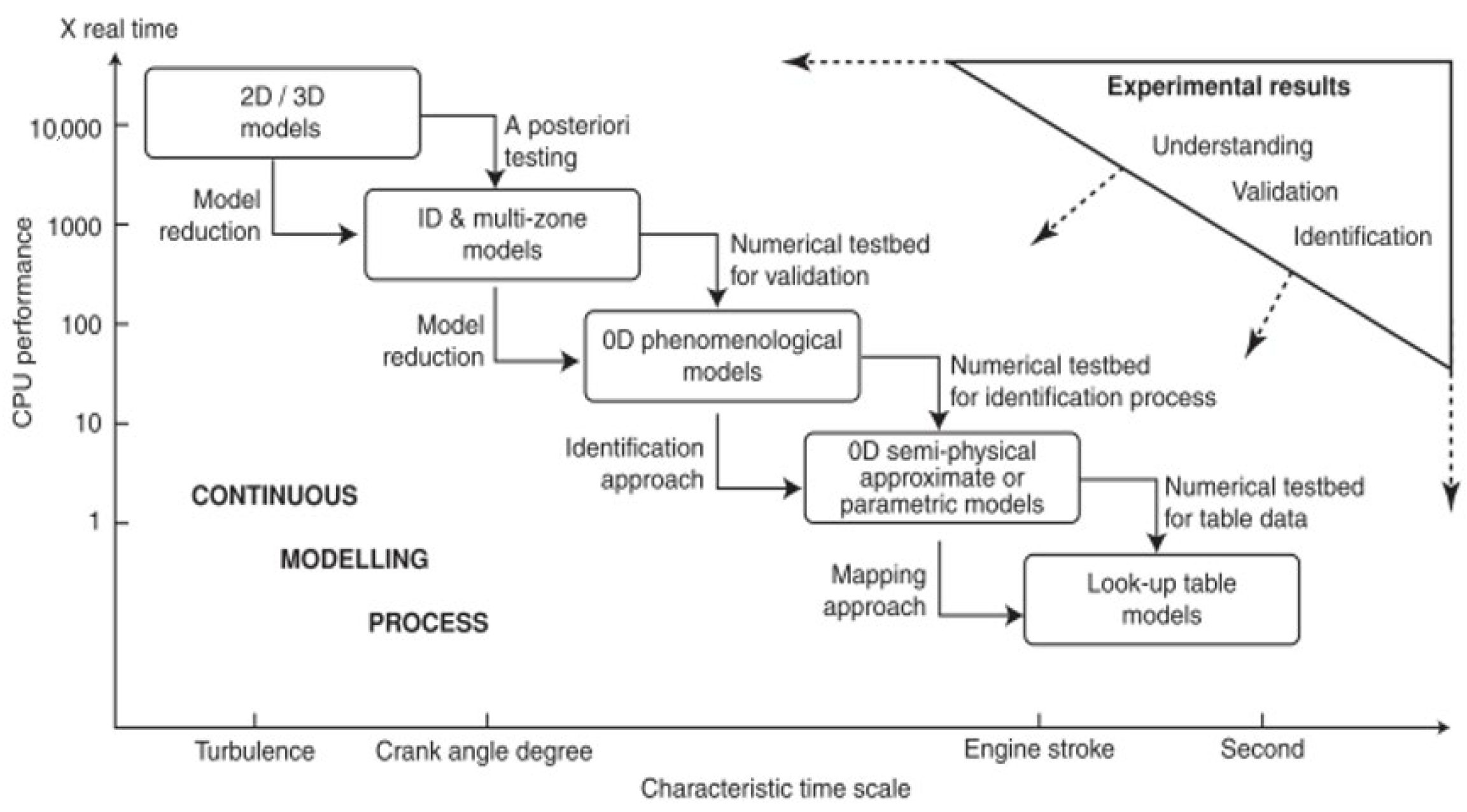
4.4. Model Fidelity and Transient Study-Oriented Reduction

To address the transient performance of gas–electric hybrid power systems on ships, primary and physics-based models have been developed for thermodynamics in the cylinder, electromagnetics in power grids, and hydrodynamics in propeller–hull interaction. These models provide insights into the dynamic behaviors during ship transient operations individually. However, there is a lack of full-scale models that cover all these sections simultaneously, primarily due to model complexity. It is worth noting that simulation time costs have become a non-negligible factor during modeling and validation. Therefore, when considering model speed and simulation precision, it is crucial to choose an appropriate level and fidelity based on the specific study scope.
As the most essential component of the power system, modeling gas engine transients is critical for system performance. Over the past few decades, many kinds of models with different time scales and simulation fidelities have been implemented for various purposes, as shown in Figure 21. The previously mentioned methods in the above chapter modeled the detailed thermodynamics in the cylinder to obtain the transient engine speed under varying loads. However, despite substantially simplifying the combustion and flow processes, calculation speed remains a limiting factor for advanced control and optimization applications.
As a result, control-oriented combustion engine models have been proposed by simplifying existing physics-based engine models. The most simplified model is the look-up table type; it is widely used in the actual engine fast control and studies at the early stage [203,204]. Outputs are determined by the inputs directly by static mapping, but they lack the ability to describe the engine system accurately. A better option is the transfer function, described as a simple first-order time delay function, representing the mechanical delay features of values, fuel injection systems, and combustion processes, as shown in Figure 22a. This model has been widely used in system-level simulation to develop and validate the optimal control algorithms, as used in [164,205,206]. These models provide fast computation speeds, but they also have disadvantages due to the curve-shape-based calibration and the lack of detailed fluctuations of the engine states.
With high thermodynamics fidelity in the cylinder, a detailed 1D thermodynamics modeling method is typically used in the transient simulation to predict the combustion process and overall engine performance, such as torque and speed outputs in varying loads. At present, this method enjoys the widest acceptance in transient situation studies. This method has been implemented in GT-Power and, then, was integrated into various loading scenarios to investigate the engine performance and test the control strategies [65,95,166,207,208,209,210,211,212]. One-dimensional simulation has also been developed on another platform; Marco et al. [115] established the dual-fuel gas engine model for comparing the influence of the turbocharger on engine power management based on the Matlab/Simulink environment. However, this kind of model still makes it hard to accomplish real-time running, limiting the design of corresponding controllers.
Owing to the need for further development on model speed toward real-time and the hardware-in-the-loop (HIL) simulation [156], as well as the control purposes, mean value models have been developed from the detailed 1D models and have been adopted in related studies to represent the gas engine transient behaviors, as shown in Figure 22b. This method allows modeling an engine cylinder using a simplified MAP-based profile. The cylinder airflow and distribution of fuel energy can be estimated by the MAPs, resulting in fast simulation compared to models with detailed components, since the scavenging and combustion behaviors are not predicted, as shown in Figure 23. It can be seen that the main differences between the detailed 1D model and the mean value model are the reduced description of the cylinder dynamics in MAP and the unified gas path sub-model in a simplified form. This kind of model has found widespread application in scenarios that require fast speed, even the real-time simulation for transient control, by ignoring the detailed heat release behavior in the cylinder [213,214,215]. Similar to the 1D detailed model, GT-Power provides the mean value function to achieve fast calculation to show the dynamic phenomenon of the power system covering combustion engines [124,213,216,217,218]. Also, it has been implemented in AMESim [219] and other platforms [220,221].
When establishing the underlying description of the mean value models (MVM), combustion engine mechanisms lead to the nonlinear feature for the physical-based models. Corresponding control strategies and advanced algorithms have been designed to achieve the high-precision transient air–fuel ratio and speed control [222,223]. Despite the similar simulation costs of nonlinear and linear models, concerning the convenience of matching with the controller, the nonlinear engine and the system dynamics functions can be linearized at specific points by the Tylor expansion [122,154]. Such models are not limited to the physical-based simulation tools, simulation software such as MATLAB/Simulink and Python have been used to build the systems.
Figure 23. Engine model reduction procedure from detailed 1D model to mean value model [224].
Jmse 11 02321 g023
Taking a similar simplification approach to the mean value model, GT-Power gives the fast running model (FRM) solution. The simplified geometry of the airflow path has been used, while the detailed cylinder has remained [225], to reduce the model complexity while keeping the predictive ability of the combustion process. Differing from the mean value model, the reduced parts in the engine pertain to the air path instead of the cylinder. In detail, simplifications of the geometries of the exhaust manifold, exhaust piping, intake manifold, compressor outlet pipes, and intake piping can be carried out to obtain the process in increasing simulation speed compared to the detailed mode by allowing the smaller parts number and larger time steps [158]. The general procedure of the model reduction from the detailed 1D model to the FRM is given in Figure 24. This leads to a faster simulation than the detailed thermodynamics modeling but cannot capture the gas flow dynamics. For transient investigation of the engine dynamics, the central part of the study is the air source time delays. The wave dynamic of the flow in manifolds can be ignored. Therefore, owing to the mature function of the GT-Power, the FRM model has been implemented for quasi-real-time and digital twin studies for combustion engines in hybrid architecture [226]. Eventually, the model reduction levels and complexity of the specific reduced parts dominate the model speed during the calculation [227,228]. According to the model fidelity and levels, the general comparison of the model speeds can be concluded as follows: look-up table model > transfer function model > fast running model > mean value model > 1D detailed model.
With the overall consideration of the model fidelity and speed, 1D detailed models are used to investigate the combustion process and engine output details during the powertrain transients. The mean value models and FRM are implemented in transient combustion engine control and fast simulations such as real-time and digital twin studies. In contrast, the simplified form models of engines, like transfer function models and look-up table models, find more application in the power system transient simulation, where the focus is on the electromagnetic dynamic instead of combustion engines in microgrids and land generation. Therefore, engine model fidelities and levels should be selected, and model reduction should be conducted in the appropriate way to be suitable for the requirements of the simulation speed and accuracy [230].
At the power system level, modeling of the power grids and propeller–hull interactions must be coupled with engine models. The same is true for these models; appropriate reductions are required for system models for various purposes. Jørgen et al. [171] compared the influence of model fidelity on the ship dynamic simulation results, indicating the necessity of the propeller wave interaction model on the propulsion efficiency estimation in transient sea conditions. Douwe et al. [231] deduced a linear model for the marine mechanical propulsion system, including hull resistance, propeller interactions, and shaft dynamics for control purposes. Then [232], this model was used in the simulation study with a motor-simulated diesel engine to investigate the feasibility of the HIL method and their control loops on the ship tank tests. In power grid simulations, combustion engines serving as prime movers are often modeled briefly, while the converters and inverters are described in detail to show the current and voltage dynamics during the transient operations, as reported in [136,143,144,164,195]. It is notable that, similar to the fidelity of the engine models in different applications, transient operation simulations for mechanical-driven ships always employ the thrust and deduction coefficients method instead of fixed value models. Electromagnetic studies for land generation and all-electric ship grids require detailed electric components modeling, while not much is required of the combustion engine models. A summary of the model fidelities in studies for various purposes is illustrated in Table 4.

5. Perspectives for Marine Gas Engine Dynamics Performance

Focusing on the transient performance of marine gas engine power systems, the previous sections have discussed the research state regarding transient behavior modeling, system and control improvements, and real ship applications. The following section provides a summary of the potential challenges that may be encountered in developing gas engine transient performance in the future, considering industrial innovations aimed at further decarbonization.

5.1. Improving the Transient Control Accuracy for Future Alternative Fuels

Owing to the gas-fueled characteristics, the gas engine has the potential to be suitable for other gas fuels with low-carbon or carbon-free features generated from green pathways, known as e-fuels, hydrogen, and ammonia [13]. Compared to natural gas, significant differences in the fuel’s physical and combustion characteristics, including heating value, knocking limits, and flame propagation speeds, can be observed for alternative fuels, resulting in the need for specialized control methods to prevent knocking and to achieve the optimal combustion during the transients.
When using hydrogen fuel in a gas engine, compared to natural gas engines, a more enormous challenge arises for the turbocharger, leading to a weaker load response. Given the fast flame propagation speed and higher knocking risk associated with hydrogen, the engine control methods of the air–fuel ratios must be improved for a smaller available working range. Additionally, feedback control is needed by monitoring the hydrogen composition inside the engine exhaust gas, especially at high loads. Meanwhile, considering the physical properties of the lower density and volume heating value of hydrogen, a larger air–fuel ratio is necessary to achieve the specific engine performance and emission levels. Therefore, more air must be supplied from the turbocharger during the running, necessitating a high compression-pressure ratio ability. However, due to the fast flame propagation speed and lean-burn combustion concept, the enthalpy and internal energy of engine exhaust gas are lower compared to natural gas engines, hence the less energy to drive the compressor and the reduced air mass flow. Existing turbochargers may struggle to meet the scavenging requirements of large-bore marine engines with high efficiency, and they can only be used with an efficiency loss of 6–8% [238,239]. This challenges the design and control of the turbocharger and other air path systems to maintain the defined air–fuel ratio. Consequently, turbochargers with higher pressure ratios and mass flow, such as axial turbochargers and multi-stage turbochargers, need to be developed, and advanced air management strategies, such as EGR combined with high-pressure boosting, must be investigated for future implementation of hydrogen fuel.
Regarding ammonia fuel, the most significant limitation of its application is the low flame propagation speed. In contrast to hydrogen, the combustion limits of ammonia engines are more likely to be dominated by the misfire phenomenon. In theory, existing turbochargers can meet the air mass requirements of ammonia engines due to the lower air–fuel ratio. However, considering the combustible limits of ammonia gas, the available working range will be narrower. This indicates the need for more precise transient air–fuel control strategies to maintain steady combustion in the cylinder during transient operations.

5.2. Overcoming the Low System Inertia When Employing Renewable Energies

Following the industrial ambitions for carbon reduction, along with the reduction in costs, the implementation of renewable energies has been considered a feasible solution for low-carbon designs with energy diversification. Along with the long-term clean benefits, power splitting during the transients by renewable energies is also crucial for ship running. Renewable energies on ships, driven by the wind, solar, and waves, are allowed to provide additional power under the control of EMS through the hybrid power architecture to reduce transient power variations on engines. However, limited by the environmental dependence of renewable energies, their power randomness and uncertainty are inevitable during their working, especially in the electric propulsion power systems. Another feature of renewable energies is their low inertia. Most renewable energies are recognized as low-inertia or even zero-inertia systems due to the lack of mechanical rotating parts [240]. This reduction in overall system inertia can affect the system’s ability to prevent frequency variation during the varying loads. On the other hand, power systems with renewable energies require generators and prime movers with higher inertia. As discussed in [241], when the prime mover in an isolated grid was replaced with a DF engine with a larger inertia, the system load response can be improved significantly under a 100% load step test. Compared to conventional combustion-engine-based power grids on ships, renewable energy power systems have more electric equipment and more complex system interactions, resulting in increased uncertainty in the system. In marine grids on ships, system stability, also known as the load response ability, is the main factor that limits the implementation of a high ratio of renewal energies. Kamala et al. [48] pointed out that the reason for the low inertia of the renewable energy system is the uncoupling of the power generation and loads caused by inverters. This feature weakens the transient performance of power systems and has become one of the key challenges that need to be addressed in the pursuit of green shipping. It indicates the need for investigation and a comprehensive understanding of the detailed system design and collaborative energy control.
Before advancing in the control and optimization of grid performance, high-accuracy modeling of such a complex power system with strong interactions between the mechanical–electrical control loops is indispensable but challenging. Therefore, model reductions can be considered to capture the system dynamics as soon as possible for various working scenarios. Following this procedure, transient modeling for small-scale power systems such as isolated grids and microgrids has become feasible for implementation. However, for large-scale power systems, such as ship grids with multiple prime movers and power sources, appropriate solutions are still lacking. To address this issue, several suppositions can be made to accomplish the model reduction with different fidelities and study scopes for specific purposes. Another pathway is the development of simulation methods, including the model speed-up algorithms and structures.
Advanced control has been an effective solution to overcome the effects of renewable energies. Mrinal et al. [242] provide a summary of the load control methods when using renewable energies. Combining the ESS and advanced control strategies has the most direct effects on filling the intermittent power blanks caused by environmental factors. Control methods for inverters and converters determine the power output characteristics of ESS and renewable energies in grids. These methods have been strengthened by superconducting magnetic energy storage, variable synchronous machines, converter control for harmonics, filter technologies, virtual impedance control, MPC, and multi-input and multi-output data-driven strategies [69,243,244]. As mentioned, the collaborative design and optimization of the system configuration and EMS have been actively discussed and implemented in related studies. Further investigations are required for larger-scale and multiple-scenario applications to improve control robustness and universality in transients.

6. Summary and Conclusions

The shipping decarbonization ambition promotes industrial innovations in gas engine and power system electrification, emphasizing the need to enhance gas engine transient performance in real sea conditions. This paper provides an overview of the current research status and the gaps in the transient performance of marine gas engines. It is organized around the perspectives of gas engine and system modeling, commercial applications, and the optimization of air path design and control methods. This paper also outlines potential challenges that need to be addressed for future implementation, offering them as points of reference.
Based on the presented transient performance requirements for marine gas engines, detailed elaborations of enhancement technologies, including air path systems development and advanced system load control from the perspectives of the gas engine itself and the ship’s power system, have been illustrated to analyze their potential and demonstrate the necessity for collaborative optimization and design. Current commercial gas engines in the shipping industry have been listed to allow the comparison of their transient performances concerning fuel supply methods. Then, the modeling methods for the main parts of marine power systems, such as combustion engines, power grids, and propeller loads, were described. Individual model fidelities for various study purposes have been compared and concluded, and recommendations for selecting the appropriate power system modeling levels were provided based on investigation and comparative analysis.
Further studies and developments are necessary to enhance the marine gas engine load response in power generation and propulsion modes for future applications. Particular emphasis should be placed on advanced air path systems and accurate transient control for carbon-free hydrogen engine operations due to the higher requirements on air mass flow and high knocking risk. In contrast, the transient control for ammonia engines will be more critical due to the narrower working range. When utilizing renewable energies such as wind, solar, and waves, their low system inertia and large power randomness can be mitigated by employing the combination of advanced control methods and ESS. However, the limitation on detailed modeling due to the complex interactions and large scale of the ship power systems still requires more investigations on model fidelity and speed.

Author Contributions

Conceptualization, S.W. and T.L.; Methodology, S.W. and T.L.; Investigation, S.W. and R.C.; Roles/writing—original draft, S.W.; Writing—review and editing, T.L., S.H. and F.X.; Supervision, T.L., R.C. and B.W. All authors have read and agreed to the published version of the manuscript.

Funding

This research was funded by the Major International (Regional) Joint Research Project of the National Natural Science Foundation of China (52020105009).

Institutional Review Board Statement

Not applicable.

Informed Consent Statement

Not applicable.

Data Availability Statement

Not applicable.

Conflicts of Interest

The authors declare no conflict of interest.

Abbreviations

CIICarbon Intensity Indicator
DTDigital Twin
ECAEmission Control Areas
EEDIEnergy Efficiency Design Index
EGRExhaust Gas Recirculation
EMSEnergy Management Strategy
ESSEnergy Storage System
ETCElectric Turbocharger
FRMFast Running Model
HILHardware In the Loop
HPDFHigh-Pressure Dual-Fuel engine
IGBTInsulated Gate Bipolar Transistors
IMOInternational Maritime Organization
LBSILean-Burn Spark Ignition
LNGLiquefied Natural Gas
LPDFLow-Pressure Dual-Fuel engine
MPCModel-Based Predictive Control
MVMMean Value Model
PIDProportional Integral Derivative controller
PVPhotovoltaic
RTReal Time
SAISecondary Air Injection
SOCState Of Charge
TFTransfer Function
VCMValve Control Management
VGTVariable Geometry Turbocharger
VSGVirtual Synchronous Generator

References

  1. Chu Van, T.; Ramirez, J.; Rainey, T.; Ristovski, Z.; Brown, R.J. Global impacts of recent IMO regulations on marine fuel oil refining processes and ship emissions. Transp. Res. Part D Transp. Environ. 2019, 70, 123–134. [Google Scholar] [CrossRef]
  2. Aakko-Saksa, P.T.; Lehtoranta, K.; Kuittinen, N.; Järvinen, A.; Jalkanen, J.-P.; Johnson, K.; Jung, H.; Ntziachristos, L.; Gagné, S.; Takahashi, C.; et al. Reduction in greenhouse gas and other emissions from ship engines: Current trends and future options. Prog. Energy Combust. Sci. 2023, 94, 101055. [Google Scholar] [CrossRef]
  3. Tan, Z.; Liu, H.; Shao, S.; Liu, J.; Chen, J. Efficiency of Chinese ECA policy on the coastal emission with evasion behavior of ships. Ocean. Coast. Manag. 2021, 208, 105635. [Google Scholar] [CrossRef]
  4. Nikopoulou, Z.; Cullinane, K.; Jensen, A. The role of a cap-and-trade market in reducing NOx and SOx emissions: Prospects and benefits for ships within the Northern European ECA. Proc. Inst. Mech. Eng. Part M J. Eng. Marit. Environ. 2012, 227, 136–154. [Google Scholar] [CrossRef]
  5. Wang, Y.; Guo, C.; Du, C.; Chen, X.; Jia, L.; Guo, X.; Chen, R.; Zhang, M.; Chen, Z.; Wang, H. Carbon peak and carbon neutrality in China: Goals, implementation path, and prospects. China Geol. 2021, 4, 720–746. [Google Scholar] [CrossRef]
  6. SZEP. Roadmap to Zero Emission from International Shipping; Ministry of Land, Infrastructure, Transport and Tourism: Tokyo, Japan, 2020. [Google Scholar]
  7. Holtbecker, R.; Luo, Y.; Nilsson, J.; Tzanos, S.; Kyrtatos, P. WiDE—An example on how digitalization creates value for ship operators. In Proceedings of the 30th CIMAC World Congress 2023, Busan, Republic of Korea, 12–16 June 2023. [Google Scholar]
  8. MORSFERA. IMO Action to Reduce Greenhouse Gas Emissions from International Shipping; International Maritime Organization (IMO): London, UK, 2021. [Google Scholar]
  9. DNV. Achieving the IMO Decarbonization Goals. Available online: https://www.dnv.com/expert-story/maritime-impact/How-newbuilds-can-comply-with-IMOs-2030-CO2-reduction-targets.html (accessed on 9 November 2023).
  10. Perčić, M.; Vladimir, N.; Fan, A. Life-cycle cost assessment of alternative marine fuels to reduce the carbon footprint in short-sea shipping: A case study of Croatia. Appl. Energy 2020, 279, 115848. [Google Scholar] [CrossRef]
  11. DNV-GL. Energy Transition Outlook 2021; DNV: Bærum, Norway, 2021. [Google Scholar]
  12. Stolz, B.; Held, M.; Georges, G.; Boulouchos, K. Techno-economic analysis of renewable fuels for ships carrying bulk cargo in Europe. Nat. Energy 2022, 7, 203–212. [Google Scholar] [CrossRef]
  13. CIMAC. Future Marine eFuels; CIMAC: Frankfurt, Germany, 2021. [Google Scholar]
  14. O’Malley, S.; Walsh, K.; Hasen, A.; Bratvold, D.; Ratafia-Brown, J. Marine Fuel Choice for Ocean Going Vessels within Emissions Control Areas; US Energy Information Administration: Washington, DC, USA, 2015. [Google Scholar]
  15. Manouchehrinia, B.; Dong, Z.; Gulliver, T.A. Well-to-Propeller environmental assessment of natural gas as a marine transportation fuel in British Columbia, Canada. Energy Rep. 2020, 6, 802–812. [Google Scholar] [CrossRef]
  16. DNV-GL. Bridging Fuels. Available online: https://www.dnv.com/maritime/hub/decarbonize-shipping/fuels/bridging-fuels.html2021 (accessed on 9 November 2023).
  17. Khan, M.I.; Yasmin, T.; Shakoor, A. Technical overview of compressed natural gas (CNG) as a transportation fuel. Renew. Sustain. Energy Rev. 2015, 51, 785–797. [Google Scholar] [CrossRef]
  18. Fan, A.; Wang, J.; He, Y.; Perčić, M.; Vladimir, N.; Yang, L. Decarbonising inland ship power system: Alternative solution and assessment method. Energy 2021, 226, 120266. [Google Scholar] [CrossRef]
  19. Clarkson. Alternative Fuels Installations by Vessel; Clarkson Research: London, UK, 2020. [Google Scholar]
  20. Formosa, W.; Sant, T.; De Marco Muscat-Fenech, C.; Figari, M. Wind-Assisted Ship Propulsion of a Series 60 Ship Using a Static Kite Sail. J. Mar. Sci. Eng. 2023, 11, 117. [Google Scholar] [CrossRef]
  21. Abdullah-Al-Mahbub, M.; Towfiqul Islam, A.R.M.; Alam, E.; Asha, M.R. Sustainable solar energy potential on marine passenger ships of Bay of Bengal: A way of reducing carbon dioxide emissions and disaster risk reduction. Energy Explor. Exploit. 2023, 41, 1697–1723. [Google Scholar] [CrossRef]
  22. Johnson, J.; Ellis, A.; Denda, A.; Morino, K.; Shinji, T.; Ogata, T.; Tadokoro, M. PV output smoothing sing a battery and natural gas engine-generator. In Proceedings of the 2013 IEEE 39th Photovoltaic Specialists Conference (PVSC), Tampa, FL, USA, 16–21 June 2013. [Google Scholar]
  23. Li, B.; Lv, J.; Deng, F.; Cui, Y.; Zhang, B. The Energy Recovery Effect of Wave Energy Utilization System under the Rolling Motion of Ships. J. Waterw. Port Coast. Ocean. Eng. 2023, 149, 04022030. [Google Scholar] [CrossRef]
  24. Leong, P. Berge Bulk Unveils the World’s Most Powerful Sailing Cargo Ship. Available online: https://www.bergebulk.com/berge-bulk-unveils-the-worlds-most-powerful-sailing-cargo-ship/2023 (accessed on 9 November 2023).
  25. Brouwer, E.; Brands, D.; Content, J.; Lenders, E. The Position of the Dutch Solar PV Sector in the European Value Chain; SEO Amsterdam: Amsterdam, The Netherlands, 2023. [Google Scholar]
  26. Naderipour, A.; Abdul-Malek, Z.; Nowdeh, S.A.; Kamyab, H.; Ramtin, A.R.; Shahrokhi, S.; Klemeš, J.J. Comparative evaluation of hybrid photovoltaic, wind, tidal and fuel cell clean system design for different regions with remote application considering cost. J. Clean. Prod. 2021, 283, 124207. [Google Scholar] [CrossRef]
  27. Tavakoli, S.; Bagherabadi, K.M.; Schramm, J.; Pedersen, E. Fuel consumption and emission reduction of marine lean-burn gas engine employing a hybrid propulsion concept. Int. J. Engine Res. 2021, 23, 1406–1416. [Google Scholar] [CrossRef]
  28. Kelling, U.S. Electric drive system for marime propulsion what can we learn from the vehicles business. In Proceedings of the 29th CIMAC World Congress 2019, Vancouver, BC, Canada, 10–14 June 2019. [Google Scholar]
  29. Nuchturee, C.; Li, T.; Xia, H. Design of Cost-Effective and Emission-Aware Power Plant System for Integrated Electric Propulsion Ships. J. Mar. Sci. Eng. 2021, 9, 684. [Google Scholar] [CrossRef]
  30. Mongird, K.; Viswanathan, V.; Balducci, P.; Alam, J. Energy Storage Technology and Cost Characterization Report; U.S. Department of Energy: Washington, DC, USA, 2019. [Google Scholar]
  31. Kim, S.; Jeon, H.; Kim, J. Trend analysis of domestic and international regulations for electric propulsion system. J. Int. Marit. Saf. Environ. Aff. Shipp. 2020, 4, 113–121. [Google Scholar] [CrossRef]
  32. ADB. Handbook on Battery Energy Storage System; Asian Development Bank: Mandaluyong, Philippines, 2018. [Google Scholar]
  33. Hou, J.; Sun, J.; Hofmann, H. Control development and performance evaluation for battery/flywheel hybrid energy storage solutions to mitigate load fluctuations in all-electric ship propulsion systems. Appl. Energy 2018, 212, 919–930. [Google Scholar] [CrossRef]
  34. Nuchturee, C.; Li, T. A review of energy efficiency improvement strategies for all electric ships. In Proceedings of the 2018 International Conference on New Energy and Future Energy System (NEFES 2018), Shanghai, China, 21–24 August 2018. [Google Scholar]
  35. Sirimanne, S.N.; Hoffmann, J.; Asariotis, R. Review of Maritime Transport 2022; UN: New York, NY, USA, 2022. [Google Scholar]
  36. Xie, Y. World’s First 700TEU Pure Battery-Powered Container Ship Sets Sail in Yangzhou. Available online: http://en.sasac.gov.cn/2023/08/02/c_15693.htm2023 (accessed on 9 November 2023).
  37. Chehrmonavari, H.; Kakaee, A.; Hosseini, S.E.; Desideri, U.; Tsatsaronis, G.; Floerchinger, G.; Braun, R.; Paykani, A. Hybridizing solid oxide fuel cells with internal combustion engines for power and propulsion systems: A review. Renew. Sustain. Energy Rev. 2023, 171, 112982. [Google Scholar] [CrossRef]
  38. Giap, V.-T.; Lee, Y.D.; Kim, Y.S.; Ahn, K.Y.; Kim, D.H.; Lee, J.I. System simulation and exergetic evaluation of hybrid propulsion system for crude oil tanker: A hybrid of solid-oxide fuel cell and gas engine. Energy Convers. Manag. 2020, 223, 113265. [Google Scholar] [CrossRef]
  39. Nuchturee, C.; Li, T.; Xia, H. Energy efficiency of integrated electric propulsion for ships—A review. Renew. Sustain. Energy Rev. 2020, 134, 110145. [Google Scholar] [CrossRef]
  40. Xing, H.; Spence, S.; Chen, H. A comprehensive review on countermeasures for CO2 emissions from ships. Renew. Sustain. Energy Rev. 2020, 134, 110222. [Google Scholar] [CrossRef]
  41. García-Olivares, A.; Solé, J.; Osychenko, O. Transportation in a 100% renewable energy system. Energy Convers. Manag. 2018, 158, 266–285. [Google Scholar] [CrossRef]
  42. Yuan, Y.; Wang, J.; Yan, X.; Shen, B.; Long, T. A review of multi-energy hybrid power system for ships. Renew. Sustain. Energy Rev. 2020, 132, 110081. [Google Scholar] [CrossRef]
  43. Theotokatos, G.; Stoumpos, S.; Bolbot, B.; Boulougouris, E.; Vassalos, D. Marine Dual Fuel Engine Control System Modelling and Safety Implications Analysis. In Proceedings of the International Naval Engineering Conference and Exhibition (INEC), Glasgow, UK, 2–4 October 2018. [Google Scholar]
  44. Mizythras, P.; Boulougouris, E.; Theotokatos, G. Numerical study of propulsion system performance during ship acceleration. Ocean. Eng. 2018, 149, 383–396. [Google Scholar] [CrossRef]
  45. Engines ICOC. Position Paper Transient Response Behaviour of Gas Engines; CIMAC: Frankfurt, Germany, 2011. [Google Scholar]
  46. Wu, S.; Li, T.; Chen, R.; Zhou, X.; Huang, S.; Wang, B. Research on dynamic performance of gas engine power systems for marine applications under the background of energy diversification—A review. In Proceedings of the 10th International Conference on Modeling and Diagnostics for Advanced Engine Systems (COMODIA 2022), Sapporo, Japan, 5–8 July 2022. [Google Scholar]
  47. Wartsila. Wartsila 31DF Product Guide; Wartsila: Helsinki, Finland, 2020; Available online: https://cdn.wartsila.com/docs/default-source/product-files/engines/df-engine/product-guide-w31df.pdf?sfvrsn=96a9145_21 (accessed on 9 November 2023).
  48. Ratnam, K.S.; Palanisamy, K.; Yang, G. Future low-inertia power systems: Requirements, issues, and solutions—A review. Renew. Sustain. Energy Rev. 2020, 124, 109773. [Google Scholar] [CrossRef]
  49. Xia, Y.; Wei, W.; Long, T.; Blaabjerg, F.; Wang, P. New Analysis Framework for Transient Stability Evaluation of DC Microgrids. IEEE Trans. Smart Grid 2020, 11, 2794–2804. [Google Scholar] [CrossRef]
  50. Daido, T.; Miura, Y.; Ise, T.; Sato, Y. Transient characteristics for load changes of a doubly fed induction generator applied to gas engine congeneration system in stand alone operation. In Proceedings of the 2012 IEEE Energy Conversion Congress and Exposition (ECCE), Raleigh, NC, USA, 15–20 September 2012. [Google Scholar]
  51. Daido, T.; Miura, Y.; Ise, T.; Sato, Y. Characteristics on Stand-alone Operation of a Doubly-fed Induction Generator Applied to Adjustable Speed Gas Engine Cogeneration System. J. Power Electron. 2013, 13, 841–853. [Google Scholar] [CrossRef]
  52. Zeng, Q.; Fang, J.; Li, J.; Chen, Z. Steady-state analysis of the integrated natural gas and electric power system with bi-directional energy conversion. Appl. Energy 2016, 184, 1483–1492. [Google Scholar] [CrossRef]
  53. Dag, S.; Ole, T. GHG and NOx Emissions from Gas Fuelled Engines; SINTEF Ocean AS: Trondheim, Norway, 2017. [Google Scholar]
  54. Heywood, J.B. Internal Combustion Engine Fundamentals, 2nd ed.; McGraw-Hill Education: New York, NY, USA, 2018. [Google Scholar]
  55. GBT 13030-2009; Specification for Electric Propulsion Plant of Ship. CSIC: Madrid, Spain, 2009.
  56. Tian, Y.; Crous, R. Reciprocating Engine Step Load Response in Islanded Power Generation. Energy Power Eng. 2013, 05, 337–343. [Google Scholar] [CrossRef]
  57. Wartsila. Wartsila 31SG Product Guide; Wartsila: Helsinki, Finland, 2020; Available online: https://cdn.wartsila.com/docs/default-source/product-files/engines/wartsila-31sg-product-guide.pdf?sfvrsn=5dada044_2 (accessed on 9 November 2023).
  58. ISO. Reciprocating Internal Combustion Engine Driven Alternating Current Generating Sets—Part 5: Generating Sets; ISO: Geneva, Switzerland, 2022. [Google Scholar]
  59. Ponte, P. Transient Performance of Generating Sets; Bulletin 5544421|Technical Information from Cummins; Cummins: Columbus, IN, USA, 2020. [Google Scholar]
  60. Latarche, M. Dual-fuel and gas engines. In Pounder’s Marine Diesel Engines and Gas Turbines; Elsevier: Amsterdam, The Netherlands, 2021; pp. 59–86. [Google Scholar]
  61. Krivopolianskii, V.; Valberg, I.; Stenersen, D.; Ushakov, S. Control of the combustion process and emission formation in marine gas engines. J. Mar. Sci. Technol. 2018, 24, 593–611. [Google Scholar] [CrossRef]
  62. Delneri, D.; Sirch, G.; Germani, M.; Zubin, L. Enhanced Flexibility in Gas Engine Operation for Marine and Power Generation Demanding Applications. In Proceedings of the 29th CIMAC World Congress 2019, Vancouver, BC, Canada, 10–14 June 2019. [Google Scholar]
  63. Benajes, J.; Luján, J.M.; Bermúdez, V.; Serrano, J.R. Modelling of turbocharged diesel engines in transient operation. Part 1: Insight into the relevant physical phenomena. Proc. Inst. Mech. Eng. Part D J. Automob. Eng. 2016, 216, 431–441. [Google Scholar] [CrossRef]
  64. CIMAC. Information Concerning the Application of Gas Engines in the Marine Industry; CIMAC: Frankfurt, Germany, 2013. [Google Scholar]
  65. Stoumpos, S.; Theotokatos, G.; Mavrelos, C.; Boulougouris, E. Towards Marine Dual Fuel Engines Digital Twins—Integrated Modelling of Thermodynamic Processes and Control System Functions. J. Mar. Sci. Eng. 2020, 8, 200. [Google Scholar] [CrossRef]
  66. Engines’, C.W.G. CIMAC Position Paper—Impact of Gas Quality on Gas Engine Performance; CIMAC: Frankfurt, Germany, 2015. [Google Scholar]
  67. Rönn, K.; Pehlivanla, B.; Göbel, C.; Pischinger, S.; Karvo, A.; Lehto, K.; Fryjan, J. Pre-ignition Behavior of Gasoline Blends in a Single–Cylinder Engine with Varying Boost Pressure and Compression Ratio. In Proceedings of the 2023 JSAE/SAE Powertrains, Energy and Lubricants International Meeting, Tokyo, Japan, 29 August 29–1 September 2023. [Google Scholar]
  68. Schneßl, E.; Wimmer, A. Trends in the Development of Large Gas Engines for Power Generation. In Proceedings of the International Conference and Workshop REMOO, Budva, Montenegro, 18 May–20 June 2016. [Google Scholar]
  69. Ushakov, S.; Stenersen, D.; Einang, P.M. Methane slip from gas fuelled ships: A comprehensive summary based on measurement data. J. Mar. Sci. Technol. 2019, 24, 1308–1325. [Google Scholar] [CrossRef]
  70. Mikko Heikkilä, J.-P.J.; Päivi Aakko-Saksa, K.L. Methane slip emissions from LNG vessels—Review. In Proceedings of the 30th CIMAC World Congress 2023, Busan, Republic of Korea, 12–16 June 2023. [Google Scholar]
  71. Wideskog, M. Introducing the World’s Largest Gas Engine; Energy/In Detail; Wärtsilä Power Plants: Chiyoda, Tokyo, 2011. [Google Scholar]
  72. WinGD. WinGD X92DF-2.0. Available online: https://www.wingd.com/en/engines/engine-types/x-df-dual-fuel/x92df-2-0/2023 (accessed on 9 November 2023).
  73. MAN. MAN Engine Products; MAN: Munich, Germany, 2020. [Google Scholar]
  74. Wartsila. Wartsila Product Guide; Wartsila Energy: Chiyoda, Tokyo, 2022. [Google Scholar]
  75. Caterpillar. Caterpillar Product Guide; Caterpillar: Irving, TX, USA, 2019. [Google Scholar]
  76. MTU. MTU Series 4000 Gas Generator Sets; MTU-Solutions: Friedrichshafen, Germany, 2021. [Google Scholar]
  77. Jenbacher. Jenbacher J Type Gas Engine; Jenbacher: Jenbach, Austria, 2022. [Google Scholar]
  78. CSSC. “Green Pearl River” Another Milestone. Available online: http://www.csic.com.cn/n135/n171/n179/c21847/content.html2022 (accessed on 9 November 2023).
  79. WEICHAI. Weichai Natural Gas Engines. Available online: https://www.weichai.com/cpyfw/wmdyw/dlzc/xnyfdj/2023 (accessed on 9 November 2023).
  80. Higashikawa, S.; Tsujioka, K.; Tanaka, T.; Tokuoka, T. Development of a low-speed four- stroke gas engine. In Proceedings of the 30th CIMAC World Congress 2023, Busan, Republic of Korea, 12–16 June 2023. [Google Scholar]
  81. Moriyoshi, Y. Current Status and Future Trend of Research on Gas Engine Combustion. J. Combust. Soc. Jpn. 2020, 62, 285–292. [Google Scholar]
  82. Zakrzewski, T.; Stephens, B. Updated generalized natural gas reciprocating engine part-load performance curves for cogeneration applications. Sci. Technol. Built Environ. 2017, 23, 1151–1158. [Google Scholar] [CrossRef]
  83. Tavakoli, S.; Jensen, M.V.; Pedersen, E.; Schramm, J. Unburned hydrocarbon formation in a natural gas engine under sea wave load conditions. J. Mar. Sci. Technol. 2020, 26, 128–140. [Google Scholar] [CrossRef]
  84. Gronholm, T.; Makela, T.; Hatakka, J.; Jalkanen, J.P.; Kuula, J.; Laurila, T.; Laakso, L.; Kukkonen, J. Evaluation of Methane Emissions Originating from LNG Ships Based on the Measurements at a Remote Marine Station. Environ. Sci. Technol. 2021, 55, 13677–13686. [Google Scholar] [CrossRef] [PubMed]
  85. Higa, N.; Hirose, K.; Nishioka, K.; Doui, M. Development of Marine Dual Fuel Engine (EY26DF). In Proceedings of the 30th CIMAC World Congress 2023, Busan, Republic of Korea, 12–16 June 2023. [Google Scholar]
  86. Delneri, D.; Axelsson, M.; Varjosaari, M.; Sirch, G. Wartsila ultra-low emission gas engine technology. In Proceedings of the 30th CIMAC World Congress 2023, Busan, Republic of Korea, 12–16 June 2023. [Google Scholar]
  87. Chen, Z.; Tang, X.; Li, X.; Hu, J.; Shi, L.; Deng, K. Collaborative optimization of EGR and Miller cycle of two-stage turbocharged marine diesel engine. In Proceedings of the 30th CIMAC World Congress 2023, Busan, Republic of Korea, 12–16 June 2023. [Google Scholar]
  88. Park, H.; Lee, Y.-S.; Jung, C.; Jung, K.; Lim, C.; Lee, H. Methane emission reduction technologies for medium-speed dual-fuel engines. In Proceedings of the 30th CIMAC World Congress 2023, Busan, Republic of Korea, 12–16 June 2023. [Google Scholar]
  89. Gutierrez, F.L.; Schneider, M.; Akira, H.; Niedziela, S.; Thalhauser, J.; Leroux, C.; Farre, G.; Sakotnig, A. Development of the next Generation Gas Engine with Increased Efficiency and Reduced Emissions. In Proceedings of the 30th CIMAC World Congress 2023, Busan, Republic of Korea, 12–16 June 2023. [Google Scholar]
  90. Moser, M.; Walther, H.-P.; Koschany, F.; Jacobsen, D. MAN Energy Solutions-Technologies to reduce methane slip of dual fuel engines. In Proceedings of the 30th CIMAC World Congress 2023, Busan, Republic of Korea, 12–16 June 2023. [Google Scholar]
  91. Zelenka, J.; Kirsten, M.; Kammel, G.; Wimmer, A. Overcoming Misfire in Large Bore Gas Engines Fueled with High Inert Content Flare Gases. In Proceedings of the 11th Dessau Gas Engine Conference, Dessau, Germany, 11–12 April 2019; pp. 140–150. [Google Scholar]
  92. Vera-Tudela, W.; Schneider, B.; Wüthrich, S.; Herrmann, K. Study on the ignitability of a high-pressure direct-injected methane jet using a scavenged pre-chamber under a wide range of conditions. Int. J. Engine Res. 2023, 24, 1603–1616. [Google Scholar] [CrossRef]
  93. Lopez Gutierrez, F.; Graus, M.; Spyra, N.; Schaumberger, H. Improved transient performance of GE’s Jenbacher type 6 gas engines. In Heavy-Duty-, On- und Off-Highway-Motoren 2015; Siebenpfeiffer, W., Ed.; Springer Fachmedien Wiesbaden: Wiesbaden, Germany, 2018; pp. 77–97. [Google Scholar]
  94. Pirker, G.; Wimmer, A. Sustainable power generation with large gas engines. Energy Convers. Manag. 2017, 149, 1048–1065. [Google Scholar] [CrossRef]
  95. Tavakoli, S.; Schramm, J.; Pedersen, E. The Effect of Air Throttle on Combustion Process and Emission Formation in Marine Lean-Burn Gas Engines. In Proceedings of the 5th World Congress on Momentum, Heat and Mass Transfer, Lisbon, Portugal, 14–16 October 2020. [Google Scholar]
  96. Tavakoli, S.; Schramm, J.; Pedersen, E. Influence of Turbocharger Inertia and Air Throttle on marine gas engine response. J. Fluid Flow Heat Mass Transf. (JFFHMT21) 2021, 8, 112–132. [Google Scholar]
  97. Park, C.; Ebisu, M.; Bae, C. Effects of turbocharger rotational inertia on engine and turbine performance in a turbocharged gasoline direct injection engine under transient and steady conditions. Int. J. Engine Res. 2021, 23, 90–103. [Google Scholar] [CrossRef]
  98. ABB. Variable Turbine Geometry VTG—The Blades of Flexibility; ABB Turbo Systems Ltd.: Baden, Switzerland, 2012. [Google Scholar]
  99. Stork, M.; Grießhaber, F.; Aurahs, L.; Münch, S.; Weihard, S.; Michael, S.M. Development of a high flow (TCF) and a high pressure (TCP) radial turbocharger series. In Proceedings of the 30th CIMAC World Congress 2023, Busan, Republic of Korea, 12–16 June 2023. [Google Scholar]
  100. Behr, T.; Kahi, M.; Reichl, A.; Hubacher, M. Seceond Generation of Two Satge Turbochaarging Power 2 Systems for Medium Speed Gas and Diesel Engines; International Council on Combustion Engines: Frankfurt, Germany, 2013. [Google Scholar]
  101. Kang, J.; Lee, B.; Jung, D. Evaluating the Effect of Two-Stage Turbocharger Configurations on the Perceived Vehicle Acceleration Using Numerical Simulation; SAE Technical Paper Series; SAE: Warrendale, PA, USA, 2016. [Google Scholar]
  102. Leng, L.; Wang, P.; Shi, L.; Deng, K. Switching process control of two-stage sequential turbocharging system for marine diesel engines. In Proceedings of the 30th CIMAC World Congress 2023, Busan, Republic of Korea, 12–16 June 2023. [Google Scholar]
  103. Marelli, S.; Usai, V. Experimental analysis and 1D simulation of an advanced hybrid boosting system for automotive applications in transient operation. Int. J. Engine Res. 2021, 24, 639–651. [Google Scholar] [CrossRef]
  104. Salehi, R.; Martz, J.; Stefanopoulou, A.; Hansen, T.; Haughton, A. Comparison of High- and Low-Pressure Electric Supercharging of a HDD Engine: Steady State and Dynamic Air-Path Considerations; SAE Technical Paper Series; SAE: Warrendale, PA, USA, 2016. [Google Scholar]
  105. Liu, R.; Ma, Y.; Yi, R.; Li, H.; Wang, X.; Wang, C.; Zheng, L. The Influence of Dual Electric Turbo Compound System on the Performance of Marine Diesel Engine. In Proceedings of the 30th CIMAC World Congress 2023, Busan, Republic of Korea, 12–16 June 2023. [Google Scholar]
  106. Baoyin, D.; Chuanlei, Y.; Yinyan, W.; Hechun, W.; Binbin, W.; Deng, H.; Baohua, W. Model-based Performance Study of Electrically Assisted Turbocharging Diesel Engine. In Proceedings of the 3rd International Conference on Mechanical Engineering and Materials (ICMEM 2022), Nanchang, China, 18–19 November 2022. [Google Scholar]
  107. Lefebvre, A.; Guilain, S. Transient Response of a Turbocharged SI Engine with an Electrical Boost Pressure Supply. In Proceedings of the 2003 JSAE/SAE International Spring Fuels and Lubricants Meeting, Yokohama, Japan, 19–22 May 2003. [Google Scholar]
  108. Zhao, D.; Stobart, R.; Mason, B. Optimising the Energy Efficiency and Transient Response of Diesel Engines through an Electric Turbocharger. In Proceedings of the 2019 American Control Conference, Philadelphia, PA, USA, 10–12 July 2019. [Google Scholar]
  109. Yadla, S.K.; Terber, D.; Keuler, J.; Davies, P. Secondary Air Injection with e-Boosting Device; Garrett Motion: Rolle, Switzerland, 2023. [Google Scholar]
  110. Zsiga, N.; Skopil, M.A.; Wang, M.; Klein, D.; Soltic, P. Comparison of Turbocharging and Pressure Wave Supercharging of a Natural Gas Engine for Light Commercial Trucks and Vans. Energies 2021, 14, 5306. [Google Scholar] [CrossRef]
  111. Galindo, J.; Climent, H.; de la Morena, J.; González-Domínguez, D.; Guilain, S. Assessment of air management strategies to improve the transient response of advanced gasoline engines operating under high EGR conditions. Energy 2023, 262, 125586. [Google Scholar] [CrossRef]
  112. Galindo, J.; Climent, H.; de la Morena, J.; González-Domínguez, D.; Guilain, S.; Besançon, T. Assessment of air-management strategies to improve the transient performance of a gasoline engine under high EGR conditions during load-decrease operation. Int. J. Engine Res. 2021, 24, 506–520. [Google Scholar] [CrossRef]
  113. Behr, T.; Hubacher, M.; Seiler, M. Second Generation Two-stage Turbocharging for Large Four-strokes. MTZ Ind. 2014, 4, 26–33. [Google Scholar] [CrossRef]
  114. Jung, M.; Ford, R.G.; Glover, K.; Collings, N.; Christen, U.; Watts, M.J. Parameterization and Transient Validation of a Variable Geometry Turbocharger for Mean-Value Modeling at Low and Medium Speed-Load Points; SAE Technical Paper 2002-01-2729; SAE International: Warrendale, PA, USA, 2002; Available online: https://saemobilus.sae.org/content/2002-01-2729/ (accessed on 9 November 2023).
  115. Altosole, M.; Balsamo, F.; Campora, U.; Mocerino, L. Marine Dual-Fuel Engines Power Smart Management by Hybrid Turbocharging Systems. J. Mar. Sci. Eng. 2021, 9, 663. [Google Scholar] [CrossRef]
  116. Leng, L.; Chen, T.; Shi, L.; Deng, K. Air-path System Transient Control of Dual-Combustion- Mode Diesel Engine Based on Universal Sliding Mode Method. In Proceedings of the 2023 JSAE/SAE Powertrains, Energy and Lubricants International Meeting, Tokyo, Japan, 29 August 29–1 September 2023. [Google Scholar]
  117. Maur, T.O.A.d. VCM’s Bright Future on the Sea; ABB: Baden, Switzerland, 2018. [Google Scholar]
  118. Claudio, C.; Ennio, C. Engine Control and Performance Enhancement with Variable Valve Train for Gas Engines. Available online: https://dokumen.tips/documents/engine-control-and-performance-enhancement-with-control-and-performance-enhancement.html?page=1 (accessed on 9 November 2023).
  119. Zelenka, J.; Christen, C.; Thalhauser, J.; Wimmer, A. Fully Variable Intake Valve Train—Advanced Air Management for Improved Dynamic Performance of Large Bore Gas Engines. In Proceedings of the 29th CIMAC World Congress 2019, Vancouver, BC, Canada, 10–14 June 2019. [Google Scholar]
  120. Yang, M.; Hu, C.; Bai, Y.; Deng, K.; Gu, Y.; Qian, Y.; Liu, B. Matching method of electric turbo compound for two-stroke low-speed marine diesel engine. Appl. Therm. Eng. 2019, 158, 113752. [Google Scholar] [CrossRef]
  121. Xia, C.; Zhang, W.; Feng, Y.; Wang, T.; Zhu, Y.; Shreka, M.; Wu, X.; Zhou, W. Investigation on control strategy optimisation of harsh transient condition for a marine natural gas engine. Ships Offshore Struct. 2022, 18, 1286–1299. [Google Scholar] [CrossRef]
  122. Harsha Rayasam, S.; Qiu, W.; Rimstidt, T.; Shaver, G.M.; Van Alstine, D.G.; Graziano, M. Control-oriented modeling, validation, and interaction analysis of turbocharged lean-burn natural gas variable speed engine. Int. J. Engine Res. 2021, 24, 738–754. [Google Scholar] [CrossRef]
  123. Ando, T.; Yamada, Y.; Suzuki, K.; Yanaka, T. Development of model-based control system for a low pressure loop EGR with a negative pressure control valve. In Proceedings of the 2023 JSAE/SAE Powertrains, Energy and Lubricants International Meeting, Tokyo, Japan, 29 August 29–1 September 2023. [Google Scholar]
  124. Wang, H.; Kolmanovsky, I.; Sun, J.; Ozaki, Y. Feedback control during mode transition for a marine dual fuel engine. In Proceedings of the International Federation of Automatic Control, Linz, Austria, 15–17 July 2015. [Google Scholar]
  125. Anand Nageswaran, B.; Rolf, D.R.; Christopher, J.R. Impact of Active Control Turbocharging on the Fuel Economy and Emissions of a Light-Duty Reactivity Controlled Compression Ignition Engine: A Simulation Study. Front. Mech. Eng. 2021, 7, 610891. [Google Scholar]
  126. HELLR. Secondary Air Injection System. Available online: https://www.hella.com/techworld/sg/Technical/Car-electronics-and-electrics/Secondary-air-injection-system-3296/2023 (accessed on 9 November 2023).
  127. Borgwarner. Electric Boosting Technologies. Available online: https://www.borgwarner.com/technologies/electric-boosting-technologies2023 (accessed on 9 November 2023).
  128. Avtotachki. Twin Turbo System. Available online: https://en.avtotachki.com/sistema-dvojnogo-turbonadduva-twin-turbo/2022 (accessed on 9 November 2023).
  129. Geertsma, R.D.; Negenborn, R.R.; Visser, K.; Hopman, J.J. Design and control of hybrid power and propulsion systems for smart ships: A review of developments. Appl. Energy 2017, 194, 30–54. [Google Scholar] [CrossRef]
  130. Li, Y.; Ding, Z.; Yu, Y.; Liu, Y. Mitigation effect of flywheel energy storage on the performance of marine gas turbine DC microgrid under high-power load mutation. Energy Rep. 2023, 9, 1380–1396. [Google Scholar] [CrossRef]
  131. Tsitsilonis, K.-M.; Theotokatos, G. A novel systematic methodology for ship propulsion engines energy management. J. Clean. Prod. 2018, 204, 212–236. [Google Scholar] [CrossRef]
  132. Dotto, A.; Sacchi, R.; Satta, F.; Campora, U. Dynamic performance simulation of combined gas electric and steam power plants for cruise-ferry ships. Next Energy 2023, 1, 100020. [Google Scholar] [CrossRef]
  133. Du, Z.; Chen, Q.; Guan, C.; Chen, H. Improvement and Optimization Configuration of Inland Ship Power and Propulsion System. J. Mar. Sci. Eng. 2023, 11, 135. [Google Scholar] [CrossRef]
  134. Sun, X.; Yao, C.; Song, E.; Liu, Z.; Yang, X.; Yang, Q. Analysis of Operating Characteristics for Marine Gas-Electric Hybrid Power System. J. Inst. Eng. (India) Ser. C 2022, 104, 1–13. [Google Scholar] [CrossRef]
  135. Xu, L.; Meng, S.; Zhou, X.; Liu, L.; Liu, Z. Research on dynamic performance optimization of marine LNG engine propulsion power system. In Proceedings of the 29th CIMAC World Congress 2019, Vancouver, BC, Canada, 10–14 June 2019. [Google Scholar]
  136. Hlaing, H.S.; Liu, J.; Miura, Y.; Bevrani, H.; Ise, T. Enhanced Performance of a Stand-Alone Gas-Engine Generator Using Virtual Synchronous Generator and Energy Storage System. IEEE Access 2019, 7, 176960–176970. [Google Scholar] [CrossRef]
  137. Bosch, R.; Casals-Torrens, P.; Alvarez-Florez, J.; Serrano-Fontova, A. Hybrid Gas-Electrical Power & Heavy Duty Propulsion: Test Platform. In Proceedings of the 19th Annual General Assembly—AGA 2018, Barcelona, Spain, 17–19 October 2018. [Google Scholar]
  138. Ito, T.; Tsukada, T.; Sato, S.; Nii, S.; Yokoyama, R. Improvement of island operating stability for lean burn gas engine by effective use of power storage device. In Proceedings of the 2011 IEEE International Conference on Smart Grid Communications (SmartGridComm), Brussels, Belgium, 17–20 October 2011; pp. 493–498. [Google Scholar]
  139. Ito, T.; Sato, S.; Arai, J.; Yokoyama, R.; Tsukada, T.; Nii, S. Effective control method of power storage system for the operating stability improvement of lean burn gas engine. In Proceedings of the 2012 Asia-Pacific Power and Energy Engineering Conference, Shanghai, China, 27–29 March 2012. [Google Scholar]
  140. Luo, Y.; Fang, S.; Kong, L.; Niu, T.; Liao, R. Dynamic power management of Shipboard Hybrid Energy Storage System under Uncertain Navigation Conditions. IEEE Trans. Transp. Electrif. 2023, 1. [Google Scholar] [CrossRef]
  141. Liu, Z.; Liu, Y.; Yu, Y.; Yang, R. Coordinated control and optimal flow of shipboard MVDC system for adapting to large pulsed power load. Electr. Power Syst. Res. 2023, 221, 109354. [Google Scholar] [CrossRef]
  142. Payvand, B.; Hosseini, S.M.H. A new method for mitigating frequency fluctuations in ships with electrical propulsion. ISA Trans. 2022, 125, 707–713. [Google Scholar] [CrossRef]
  143. Hlaing, H.S.; Miura, Y.; Ise, T. A permanent magnet synchronous generator control approach for stand alone gas engine generation system. In Proceedings of the 2016 IEEE 8th International Power Electronics and Motion Control Conference (IPEMC-ECCE Asia), Hefei, China, 22–26 May 2016. [Google Scholar]
  144. Hlaing, H.S.; Liu, J.; Bevrani, H.; Ise, T. PMSG Control for a Stand-Alone Gas Engine Generator Using Active Rectifier and VSG-Controlled Inverter. Energies 2020, 13, 233. [Google Scholar] [CrossRef]
  145. Dickinson, P.; Glover, K.; Collings, N.; Yamashita, Y.; Yashiro, Y.; Hoshi, T. Transient Evaluation of Two-Stage Turbocharger Configurations Using Model Predictive Control; SAE Technical Paper 2015-01-1980; SAE: Warrendale, PA, USA, 2015. [Google Scholar] [CrossRef]
  146. Figari, M.; Theotokatos, G.; Coraddu, A.; Stoumpos, S.; Mondella, T. Parametric investigation and optimal selection of the hybrid turbocharger system for a large marine four-stroke dual-fuel engine. Appl. Therm. Eng. 2022, 208, 117991. [Google Scholar] [CrossRef]
  147. ABB. Valve Control Management–VCM® The Flexibility to Meet Future Challenges; ABB Turbo Systems Ltd.: Baden, Switzerland, 2016. [Google Scholar]
  148. Zelenka, J.; Christen, C.; Hoff, C.; Wimmer, A. Optimum operations strategies fro gas engines using variable intake valve tarin. In Proceedings of the ASME 2018 Internal Combustion Engine Division Fall Technical Conference ICEF2018, San Diego, CA, USA, 4–7 November 2018. [Google Scholar]
  149. Ammann, M.; Fekete, N.; Guzzella, L.; Glattfelder, A. Model-Based Control of the VGT and EGR in a Turbocharged Common-Rail Diesel Engine Theory and Passenger Car Implementation; SAE Technical: Warrendale, PA, USA, 2003. [Google Scholar]
  150. Chen, R.; Kuboyama, T.; Moriyoshi, Y.; Yasueda, S.; Doyen, V.; Martin, J.-B. Effects of Engine Operating Condition and Fuel Property on Pre-Ignition Phenomenon in a Highly Boosted Premixed Natural Gas Engine; SAE International: Warrendale, PA, USA, 2019. [Google Scholar]
  151. Tilz, A.; Kiesling, C.; Meyer, G.; Nickl, A.; Pirker, G.; Wimmer, A. Experimental investigation of the influence of ignition system parameters on combustion behavior in large lean burn spark ignited gas engines. Exp. Therm. Fluid Sci. 2020, 119, 110176. [Google Scholar] [CrossRef]
  152. Cao, E.; Liu, B.; Dong, J.; Zhou, X. Design of a Low Cost and Flexible Supercharging System for a Low- Speed Single Cylinder Engine. In Proceedings of the 30th CIMAC World Congress 2023, Busan, Republic of Korea, 12–16 June 2023. [Google Scholar]
  153. Li, G.H.; Zhang, B.H.; Hao, Z.G.; Wang, J.; Bo, Z.Q.; Writer, D.; Yip, T. Modeling of DFIG based wind generator and transient characteristics analysis. In Proceedings of the 2011 10th International Conference on Environment and Electrical Engineering, Rome, Italy, 8–11 May 2011. [Google Scholar]
  154. Gong, Q.; Ye, J.; Xu, J.; Xiong, W.; Feng, H.; Wang, D.; Shen, A. Hybrid model predictive control for premixed natural gas engine as distributed generator. Energy 2023, 278, 127728. [Google Scholar] [CrossRef]
  155. Belmonte, M.A.R. Contribution to the Experimental Characterization and 1-D Modelling of Turbochargers for IC Engines; Universidad Polit’ecnica de Valencia: Valencia, Spain, 2013. [Google Scholar]
  156. Millet, J.-B.; Maroteaux, F.; Aubertin, F. Air System and Diesel Combustion Modeling for Hardware in the Loop Applications. J. Eng. Gas Turbines Power 2012, 134, 042802. [Google Scholar] [CrossRef]
  157. Yum, K.K.; Taskar, B.; Pedersen, E.; Steen, S. Simulation of a two-stroke diesel engine for propulsion in waves. Int. J. Nav. Archit. Ocean. Eng. 2017, 9, 351–372. [Google Scholar] [CrossRef]
  158. IDAJ. GT-Suite Guide; GT-Power: Malvern, PA, USA, 2020. [Google Scholar]
  159. Xu, S.; Anderson, D.; Singh, A.; Hoffman, M.; Prucka, R.; Filipi, Z. Development of a Phenomenological Dual-Fuel Natural Gas Diesel Engine Simulation and Its Use for Analysis of Transient Operations. SAE Int. J. Engines 2014, 7, 1665–1673. [Google Scholar] [CrossRef]
  160. Stoumpos, S.; Theotokatos, G.; Boulougouris, E.; Vassalos, D.; Lazakis, I.; Livanos, G. Marine dual fuel engine modelling and parametric investigation of engine settings effect on performance-emissions trade-offs. Ocean. Eng. 2018, 157, 376–386. [Google Scholar] [CrossRef]
  161. Shen, T.; Zhang, J.; Jiao, X.; Kang, M.; Kako, J.-i.; Ohata, A. Transient Control of Gasoline Engines; Routledge: Oxfordshire, UK, 2015. [Google Scholar]
  162. Misono, Y.; Kuboyama, T.; Moriyoshi, Y.; Yamada, T. Improvement in accuracy of engine cycle simulations by using a turbocharger prediction model instead of measured efficiency map. J. Phys. Conf. Ser. 2021, 1909, 012027. [Google Scholar] [CrossRef]
  163. Yum, K.K.; Pedersen, E. Architecture of model libraries for modelling turbocharged diesel engines. Math. Comput. Model. Dyn. Syst. 2016, 22, 584–612. [Google Scholar] [CrossRef]
  164. Katiraei, F. Computer Simulation Modeling and Analysis of the Danamic Behavior of a Reciprocating Engine Based Distributed Generation Unit during Island Transition; CANMET Energy Technology Centre—Varennes Natural Resources Canada: Varennes, QC, Canada, 2007. [Google Scholar]
  165. Martelli, M.; Figari, M. Real-Time model-based design for CODLAG propulsion control strategies. Ocean Eng. 2017, 141, 265–276. [Google Scholar] [CrossRef]
  166. Huo, T.; Yao, C.; Li, W. Model-Based Simulation Research for Speed Control of Marine Low-Speed Dual Fuel Engine. In Proceedings of the 30th CIMAC World Congress 2023, Busan, Republic of Korea, 12–16 June 2023. [Google Scholar]
  167. Han, Y.; Richards, D. Significant aftertreatment cost reduction with high precise AFR control for gaseous-fueled engines. In Proceedings of the 30th CIMAC World Congress 2023, Busan, Republic of Korea, 12–16 June 2023. [Google Scholar]
  168. Kronos. Kronos Gas Engine Control Systems; Kronos: Lowell, MA, USA, 2023. [Google Scholar]
  169. Holt, P.; Nielsen, U.D. Preliminary assessment of increased main engine load as a consequence of added wave resistance in the light of minimum propulsion power. Appl. Ocean. Res. 2021, 108, 102543. [Google Scholar] [CrossRef]
  170. Saettone, S.; Tavakoli, S.; Taskar, B.; Jensen, M.V.; Pedersen, E.; Schramm, J.; Steen, S.; Andersen, P. The importance of the engine-propeller model accuracy on the performance prediction of a marine propulsion system in the presence of waves. Appl. Ocean. Res. 2020, 103, 102320. [Google Scholar] [CrossRef]
  171. Nielsen, J.B.; Sandvik, E.; Pedersen, E.; Asbjørnslett, B.E.; Fagerholt, K. Impact of simulation model fidelity and simulation method on ship operational performance evaluation in sea passage scenarios. Ocean. Eng. 2019, 188, 106268. [Google Scholar] [CrossRef]
  172. Blendermann, W. Wind Loading of Ships: Collected Data from Wind Tunnel Tests in Uniform Flow; Inst. für Schiffbau: Hamburg, Germany, 1996. [Google Scholar]
  173. Fujiwara, T.; Ueno, M.; Ikeda, Y. A New Estimation Method of Wind Forces and Moments acting on Ships on the basis of Physical Component Models. Jpn. Soc. Shipbuild. Mar. Eng. 1994, 2, 243–255. [Google Scholar]
  174. Kramel, D.; Muri, H.; Kim, Y.; Lonka, R.; Nielsen, J.B.; Ringvold, A.L.; Bouman, E.A.; Steen, S.; Strømman, A.H. Global Shipping Emissions from a Well-to-Wake Perspective: The MariTEAM Model. Environ. Sci. Technol. 2021, 55, 15040–15050. [Google Scholar] [CrossRef]
  175. Tillig, F.; Ringsberg, J.W.; Psaraftis, H.N.; Zis, T. Reduced environmental impact of marine transport through speed reduction and wind assisted propulsion. Transp. Res. Part D Transp. Environ. 2020, 83, 102380. [Google Scholar] [CrossRef]
  176. Martinsen, M.A. A Design Tool for Estimating the Added Wave Resistance of Container Ships. Master’s Thesis, Technical University of Denmark, Kongens Lyngby, Denmark, 2016. [Google Scholar]
  177. ITTC. Recommended procedures and guidelines: 1978 ITTC performance prediction method. In Proceedings of the International Towing Tank Conference 2017, Wuxi, China, 17–22 September 2017. [Google Scholar]
  178. van den Boom, H.; Huisman, H.; Mennen, F. New Guidelines for Speed/Power Trials. Level Playing Field Established for IMO EEDI; SWZ Maritime: Rotterdam, The Netherlands, 2013; pp. 1–11. [Google Scholar]
  179. Liu, S.; Shang, B.; Papanikolaou, A.; Bolbot, V. Improved formula for estimating added resistance of ships in engineering applications. J. Mar. Sci. Appl. 2016, 15, 442–451. [Google Scholar] [CrossRef]
  180. Liu, S.; Papanikolaou, A. Regression analysis of experimental data for added resistance in waves of arbitrary heading and development of a semi-empirical formula. Ocean Eng. 2020, 206, 107357. [Google Scholar] [CrossRef]
  181. Kim, Y.-R.; Steen, S.; Kramel, D.; Muri, H.; Strømman, A.H. Modelling of ship resistance and power consumption for the global fleet: The MariTEAM model. Ocean Eng. 2023, 281, 114758. [Google Scholar] [CrossRef]
  182. ECMWF ERA5. Available online: https://www.ecmwf.int/en/forecasts/datasets/archive-datasets/reanalysis-datasets/era5.2018 (accessed on 9 November 2023).
  183. Hasselmann, K.; Barnett, T.P.; Bouws, E.; Carlson, H.; Cartwright, D.E.; Enke, K.; Ewing, J.; Gienapp, A.; Hasselmann, D.; Kruseman, P. Measurements of wind-wave growth and swell decay during the Joint North Sea Wave Project (JONSWAP); Technical Report; Deutches Hydrographisches Institut: Hamburg, Germany, 1973. [Google Scholar]
  184. Tavakoli, S.; Saettone, S.; Steen, S.; Andersen, P.; Schramm, J.; Pedersen, E. Modeling and analysis of performance and emissions of marine lean-burn natural gas engine propulsion in waves. Appl. Energy 2020, 279, 115904. [Google Scholar] [CrossRef]
  185. Saettone, S.; Taskar, B.; Regener, P.B.; Andersen, P. Unsteady propeller forces and hull pressure pulses in waves. In Proceedings of the NuTTS’18, Cortona, Italy, 30 September–2 October 2018. [Google Scholar]
  186. Marques, C.H.; Belchior, C.R.P.; Caprace, J.D. Optimising the engine-propeller matching for a liquefied natural gas carrier under rough weather. Appl. Energy 2018, 232, 187–196. [Google Scholar] [CrossRef]
  187. Taskar, B.; Yum, K.K.; Steen, S.; Pedersen, E. The effect of waves on engine-propeller dynamics and propulsion performance of ships. Ocean Eng. 2016, 122, 262–277. [Google Scholar] [CrossRef]
  188. Acanfora, M.; Altosole, M.; Balsamo, F.; Micoli, L.; Campora, U. Simulation Modeling of a Ship Propulsion System in Waves for Control Purposes. J. Mar. Sci. Eng. 2021, 10, 36. [Google Scholar] [CrossRef]
  189. Oleksiy, B.; Yasushi, K. Application of the Kalman filtering technique for nonlinear state estimation in propulsion system. J. Mar. Sci. Technol. 2020, 26, 618–631. [Google Scholar]
  190. Geertsma, R.D.; Negenborn, R.R.; Visser, K.; Loonstijn, M.A.; Hopman, J.J. Pitch control for ships with diesel mechanical and hybrid propulsion: Modelling, validation and performance quantification. Appl. Energy 2017, 206, 1609–1631. [Google Scholar] [CrossRef]
  191. IMO. Fourth IMO GHG Study 2020; IMO: London, UK, 2021. [Google Scholar]
  192. Shi, J.; Amgai, R.; Abdelwahed, S. Modelling of shipboard medium-voltage direct current system for system level dynamic analysis. IET Electr. Syst. Transp. 2015, 5, 156–165. [Google Scholar] [CrossRef]
  193. Hlaing, H.S. Studies on Enhanced Performance of a Stand-Alone Gas Engine Generator with a Permanent Magnet Synchronous Generator by Applying Active Rectifier and Virtual Synchronous Generator Control. Ph.D. Thesis, Graduate School of Engineering, Osaka University, Osaka, Japan, 2020. [Google Scholar]
  194. Alafnan, H.; Zhang, M.; Yuan, W.; Zhu, J.; Li, J.; Elshiekh, M.; Li, X. Stability Improvement of DC Power Systems in an All-Electric Ship Using Hybrid SMES/Battery. IEEE Trans. Appl. Supercond. 2018, 28, 1–6. [Google Scholar] [CrossRef]
  195. Xu, Y.; Yang, Z.; Jiao, K.; Hao, D.; Du, Q. Development of a comprehensive transient fuel cell-battery hybrid system model and rule-based energy management strategy. Int. J. Green Energy 2022, 20, 844–858. [Google Scholar] [CrossRef]
  196. Pan, H.; Feng, X.; Li, F.; Yang, J. Energy coordinated control of DC microgrid integrated incorporating PV, energy storage and EV charging. Appl. Energy 2023, 342, 121155. [Google Scholar] [CrossRef]
  197. He, H.; Xiong, R.; Guo, H.; Li, S. Comparison study on the battery models used for the energy management of batteries in electric vehicles. Energy Convers. Manag. 2012, 64, 113–121. [Google Scholar] [CrossRef]
  198. Mylonopoulos, F.; Polinder, H.; Coraddu, A. A Comprehensive Review of Modeling and Optimization Methods for Ship Energy Systems. IEEE Access 2023, 11, 32697–32707. [Google Scholar] [CrossRef]
  199. de Siqueira, L.M.S.; Peng, W. Control strategy to smooth wind power output using battery energy storage system: A review. J. Energy Storage 2021, 35, 102252. [Google Scholar] [CrossRef]
  200. Hou, J.; Song, Z.; Park, H.; Hofmann, H.; Sun, J. Implementation and evaluation of real-time model predictive control for load fluctuations mitigation in all-electric ship propulsion systems. Appl. Energy 2018, 230, 62–77. [Google Scholar] [CrossRef]
  201. Fang, C.; Chai, W.; Gu, H.; Wang, L.; Cai, X. A fuzzy control scheme of the wind-storage combined system for power complementary. In Proceedings of the 2016 IEEE 8th International Power Electronics and Motion Control Conference (IPEMC-ECCE Asia), Hefei, China, 22–26 May 2016; pp. 1474–1479. [Google Scholar]
  202. Albrecht, A.; Grondin, O.; Le Berr, F.; Le Solliec, G. Towards a stronger simulation support for engine control design: A methodological point of view. Oil Gas Sci. Technol. 2007, 62, 437–456. [Google Scholar] [CrossRef]
  203. Amin, A.A.; Mahmood-ul-Hasan, K. Robust Passive Fault Tolerant Control for Air Fuel Ratio Control of Internal Combustion Gasoline Engine for Sensor and Actuator Faults. IETE J. Res. 2023, 69, 2846–2861. [Google Scholar] [CrossRef]
  204. Ju, F.; Murgovski, N.; Zhuang, W.; Hu, X.; Song, Z.; Wang, L. Predictive energy management with engine switching control for hybrid electric vehicle via ADMM. Energy 2023, 263, 125971. [Google Scholar] [CrossRef]
  205. Renjit, A.A.; Illindala, M.S.; Klapp, D.A. Modeling and analysis of the CERTS microgrid with natural gas-powered distributed energy resouurces. In Proceedings of the 2015 IEEE/IAS 51st Industrial & Commercial Power Systems Technical Conference (I&CPS), Calgary, AB, Canada, 5–8 May 2015. [Google Scholar]
  206. Westman, J.; Hadidi, R.; Fox, C.; Leonard, J. Modeling of a Reciprocating Engine-Generator Set for Controller Hardware in the Loop Testing of Island Microgrid Control Systems. In Proceedings of the 2020 IEEE Industry Applications Society Annual Meeting, Detroit, MI, USA, 10–16 October 2020; pp. 1–7. [Google Scholar]
  207. Rayasam, S.H.; Qiu, W.; Rimstidt, T.; Shaver, G.M.; Van Alstine, D.G. Robust model-based switching MIMO air handling control of turbocharged lean-burn SI natural gas variable speed engines. Int. J. Engine Res. 2022, 24, 2783–2804. [Google Scholar] [CrossRef]
  208. Robertson, D.; Conway, G.; Chadwell, C.; McDonald, J.; Barba, D.; Stuhldreher, M.; Birckett, A. Predictive GT-Power Simulation for VNT Matching on a 1.6 L Turbocharged GDI Engine; SAE Technical Paper Series; SAE: Warrendale, PA, USA, 2018. [Google Scholar]
  209. Tahtouh, T.; Andre, M.; Millo, F.; Rolando, L.; Castellano, G.; Bocchieri, F.; Cambriglia, L.; Raimondo, D. Development of a Digital Twin to Support the Calibration of a Highly Efficient Spark Ignition Engine; SAE Technical Paper Series; SAE: Warrendale, PA, USA, 2023. [Google Scholar]
  210. Theotokatos, G.; Stoumpos, S.; Bolbot, V.; Boulougouris, E. Simulation-based investigation of a marine dual-fuel engine. J. Mar. Eng. Technol. 2020, 19, 5–16. [Google Scholar] [CrossRef]
  211. Wang, Z.; Ma, C.; Wang, H. An evaluation method for transient response performance of a turbocharger in gasoline engine: Simulation and experiment. Proc. Inst. Mech. Eng. Part A J. Power Energy 2022, 237, 67–78. [Google Scholar] [CrossRef]
  212. Xia, C.; Zhu, Y.; Zhou, S.; Peng, H.; Feng, Y.; Zhou, W.; Shi, J.; Zhang, J. Simulation study on transient performance of a marine engine matched with high-pressure SCR system. Int. J. Engine Res. 2022, 24, 1327–1345. [Google Scholar] [CrossRef]
  213. Bastidaa, H.; Ugalde-Looa, C.E.; Abeysekeraa, M. Dynamic modeling and control of a reciprocating engine. In Proceedings of the 9th International Conference on Applied Energy ICAE2017, Cardiff, UK, 21–24 August 2017. [Google Scholar]
  214. Figari, M.; Altosole, M. Effective simple methods for numerical modelling of marine engines in ship propulsion control systems design. J. Nav. Archit. Mar. Eng. 2011, 8, 129–147. [Google Scholar]
  215. Nahim, H.M.; Younes, R.; Nohra, C.; Ouladsine, M. Complete modeling for systems of a marine diesel engine. J. Mar. Sci. Appl. 2015, 14, 93–104. [Google Scholar] [CrossRef]
  216. Sui, C.; de Vos, P.; Stapersma, D.; Visser, K.; Hopman, H.; Ding, Y. Mean value first principle engine model for predicting dynamic behaviour of two-stroke marine diesel engine in various ship propulsion operations. Int. J. Nav. Archit. Ocean. Eng. 2022, 14, 100432. [Google Scholar] [CrossRef]
  217. Tang, H.; Copeland, C.; Akehurst, S.; Brace, C.; Davies, P.; Pohorelsky, L.; Smith, L.; Capon, G. A novel predictive semi-physical feed-forward turbocharging system transient control strategy based on mean-value turbocharger model. Int. J. Engine Res. 2016, 18, 765–775. [Google Scholar] [CrossRef]
  218. Altosole, M.; Campora, U.; Figari, M.; Laviola, M.; Martelli, M. A Diesel Engine Modelling Approach for Ship Propulsion Real-Time Simulators. J. Mar. Sci. Eng. 2019, 7, 138. [Google Scholar] [CrossRef]
  219. Albrecht, A.; Knop, V.; Corde, G.; Simonet, L.; Castagné, M. Observer Design for Downsized Gasoline Engine Control Using 1D Engine Simulation. Oil Gas Sci. Technol. 2007, 61, 165–179. [Google Scholar] [CrossRef]
  220. Mayr, P.; Pirker, G.; Wimmer, A.; Krenn, M. Simulation-Based Control of Transient SCE Operation; SAE Technical Paper 2017-01-0544; SAE International: Warrendale, PA, USA, 2017. [Google Scholar] [CrossRef]
  221. Gambarotta, A.; Lucchetti, G.; Vaja, I. Real-time modelling of transient operation of turbocharged diesel engines. Proc. Inst. Mech. Eng. Part D J. Automob. Eng. 2011, 225, 1186–1203. [Google Scholar] [CrossRef]
  222. Alsuwian, T.; Amin, A.A.; Iqbal, M.S.; Qadir, M.B.; Almasabi, S.; Jalalah, M. Design of Active Fault-Tolerant Control System for Air-Fuel Ratio control of Internal Combustion engine using nonlinear regression-based observer model. PLoS ONE 2022, 17, e0279101. [Google Scholar] [CrossRef] [PubMed]
  223. Al Jarrah, M.A.; Jarrah, A.; Alawaisah, A. Automotive engine idle speed controller: Nonlinear model predictive control utilizing the firefly algorithm. Comput. Electr. Eng. 2023, 108, 108688. [Google Scholar] [CrossRef]
  224. Wan, P.; Liu, B.; Li, B.; Liu, F.; Zhang, J.; Fan, W.; Tang, J. Engine modelling architecture study for hybrid electric vehicle diagnosis application. Energy 2023, 282, 128408. [Google Scholar] [CrossRef]
  225. Wu, H.; Li, M.-F. A Hardware-in-the-Loop (HIL) Bench Test of a GT-Power Fast Running Model for Rapid Control Prototyping (RCP) Verification; SAE Technical Paper Series; SAE: Warrendale, PA, USA, 2016. [Google Scholar]
  226. Millo, F.; Di Lorenzo, G.; Servetto, E.; Capra, A.; Pettiti, M. Analysis of the Performance of a Turbocharged S.I. Engine under Transient Operating Conditions by Means of Fast Running Models. SAE Int. J. Engines 2013, 6, 968–978. [Google Scholar] [CrossRef]
  227. Ogata, K.; Matsuda, H.; Kawai, H.; Shiota, K. Highly efficient development of powertrain systems using 1D Real-Time Engine Model. In Proceedings of the 2023 JSAE/SAE Powertrains, Energy and Lubricants International Meeting, Tokyo, Japan, 29 August–1 September 2023. [Google Scholar]
  228. Sharma, R.; Nesic, D.; Manzie, C. Model Reduction of Turbocharged (TC) Spark Ignition (SI) Engines. IEEE Trans. Control. Syst. Technol. 2011, 19, 297–310. [Google Scholar] [CrossRef]
  229. Söderäng, E.; Hautala, S.; Mikulski, M.; Storm, X.; Niemi, S. Development of a digital twin for real-time simulation of a combustion engine-based power plant with battery storage and grid coupling. Energy Convers. Manag. 2022, 266, 115793. [Google Scholar] [CrossRef]
  230. Tang, J.; Zhu, G.G.; Men, Y. Review of engine control-oriented combustion models. Int. J. Engine Res. 2021, 23, 347–368. [Google Scholar] [CrossRef]
  231. Stapersma, D.; Vrijdag, A. Linearisation of a ship propulsion system model. Ocean Eng. 2017, 142, 441–457. [Google Scholar] [CrossRef]
  232. Huijgens, L.; Vrijdag, A.; Hopman, H. Hardware in the loop experiments with ship propulsion systems in the towing tank: Scale effects, corrections and demonstration. Ocean Eng. 2021, 226, 108789. [Google Scholar] [CrossRef]
  233. Theotokatos, G.P. Ship propulsion plant transient response investment using a mean value model. Int. J. Energy 2008, 4, 66–74. [Google Scholar]
  234. Foteinos, M.; Christofilis, G.; Kyrtatos, N. Transient Operation of a Large Two Stroke Marine Diesel Engine Equipped with a High-Pressure SCR Aftertreatment System in Heavy Weather Conditions. In Proceedings of the 29th CIMAC World Congress 2019, Vancouver, BC, Canada, 10–14 June 2019. [Google Scholar]
  235. Foteinos, M.I.; Christofilis, G.I.; Kyrtatos, N.P. Response of a direct-drive large marine two-stroke engine coupled to a selective catalytic reduction exhaust aftertreatment system when operating in waves. Proc. Inst. Mech. Eng. Part M J. Eng. Marit. Environ. 2020, 234, 651–667. [Google Scholar] [CrossRef]
  236. Mestemaker, B.T.W.; Goncalves Castro, M.B.; van den Heuvel, H.N.; Visser, K. Dynamic simulation of a vessel drive system with dual fuel engines and energy storage. Energy 2020, 194, 116792. [Google Scholar] [CrossRef]
  237. Kranawetter, K.; Seeber, R.; Mayr, P.; Pirker, G.; Bauer, R.; Horn, M. Charge Air and Fuel Gas Pressure Control on a HiL Development of Transient Large Bore Gas. In Proceedings of the 2018 IEEE Conference on Control Technology and Applications (CCTA), Copenhagen, Denmark, 21–24 August 2018. [Google Scholar]
  238. Käseberg, S.; Risse, S.; Schröder, B.G.H.; Schulz, O. Alternative fuels and their consequences for exhaust gas turbocharging. In Proceedings of the CIMAC2023, Busan, Republic of Korea, 12–16 June 2023. [Google Scholar]
  239. Ryser, R.; Bessonnard, C.; Wimmer, A. Influence of blend ratio on turbocharging & combustion in HS gas eng. applications with CH4H2 blend. In Proceedings of the 30th CIMAC World Congress 2023, Busan, Republic of Korea, 12–16 June 2023. [Google Scholar]
  240. Muljadi, E.; Butterfield, C.P.; Parsons, B.; Ellis, A. Effect of Variable Speed Wind Turbine Generator on Stability of a Weak Grid. IEEE Trans. Energy Convers. 2007, 22, 29–36. [Google Scholar] [CrossRef]
  241. Carpanese, M.P.; D’Agostino, F.; Gabriele, B.; Silvestro, F.; Trasverso, A.; Sala, S.; Tucker, D.; Bellotti, D.; Pais, T.; Vaccaro, L.; et al. Contribution to Electrical System Inertia of Dual Fuel two-stroke Engines in Isolated Grid: A Case Study. E3S Web Conf. 2023, 414, 02001. [Google Scholar]
  242. Ranjan, M.; Shankar, R. A literature survey on load frequency control considering renewable energy integration in power system: Recent trends and future prospects. J. Energy Storage 2022, 45, 103717. [Google Scholar] [CrossRef]
  243. Basit, M.A.; Dilshad, S.; Badar, R.; Sami ur Rehman, S.M. Limitations, challenges, and solution approaches in grid-connected renewable energy systems. Int. J. Energy Res. 2020, 44, 4132–4162. [Google Scholar] [CrossRef]
  244. Srivastava, V.; Schaub, J.; Pischinger, S. Model-based closed-loop control strategies for flex-fuel capability. Appl. Energy 2023, 350, 121795. [Google Scholar] [CrossRef]
Figure 1. Operation filed for Wartsila 31DF gas engine under propeller condition [47].
Jmse 11 02321 g001
Figure 2. Application modes of the gas engine on ships [57]: (a) generation mode and (b) propulsion mode.
Jmse 11 02321 g002
Figure 3. Engine transient performance characteristics during varying load [59].
Jmse 11 02321 g003
Figure 4. Various types of gas engines by fuel supply methods [53].
Jmse 11 02321 g004
Figure 5. Working ranges of diesel engines and port injection gas engines: (a) DIESEL combustion and (b) OTTO combustion at low loads; and (c) DIESEL combustion and (d) OTTO combustion at high loads [45].
Jmse 11 02321 g005
Figure 6. Distribution of gas engines by types on ships [70].
Jmse 11 02321 g006
Figure 8. Commercial pure gas engines: (ae) gas engines for generation mode, (a) Wartsila 31/34/50SG, (b) MAN 51/60 35/44G, (c) Kawasaki KG series, and (d) JENBACHER INNIO J Type; and (fi) gas engines for propulsion mode, (f) Bergen B/C series, (g) MTU IRONMEN, (h) HECHAI, and (i) WEICHAI.
Jmse 11 02321 g008
Figure 10. Advanced air supply system framework diagrams: (a) air direct injection [126]; (b) electric turbocharger [127]; (c) two-stage turbocharger [128].
Jmse 11 02321 g010
Figure 11. Hybrid power concept and ESS help to achieve load splitting [136].
Jmse 11 02321 g011
Figure 12. Multi-time-scale dynamic coupling in a marine gas engine power system: (a) generation and electric propulsion mode; (b) direct drive mode.
Jmse 11 02321 g012
Figure 13. Gas engine system architecture [154].
Jmse 11 02321 g013
Figure 14. A cylinder model consists of multiple sub-models [157].
Jmse 11 02321 g014
Figure 15. Turbocharger MAP for a lean-burn gas engine [115].
Jmse 11 02321 g015
Figure 16. Speed/load and A/F control loop of the premixed gas engines [168].
Jmse 11 02321 g016
Figure 17. Physical factors that affect the engine loads in real sea conditions [171].
Jmse 11 02321 g017
Figure 18. System framework and control loops of gas–electric power system.
Jmse 11 02321 g018
Figure 19. IGBT-based rectifier control and VSG method scheme [144].
Jmse 11 02321 g019
Figure 20. Control strategies for hybrid power systems with ESS [199]: (a) PID, (b) fuzzy, and (c) MPC control.
Jmse 11 02321 g020
Figure 21. Engine models and fidelities [202].
Jmse 11 02321 g021
Figure 22. Control-oriented engine models [161]: (a) transfer function model and (b) mean value model.
Jmse 11 02321 g022
Figure 24. Engine model reduction procedure from detailed 1D model to FRM model [229].
Jmse 11 02321 g024
Table 1. Performance comparison of various engines [68].
PerformanceDiesel Engine Pure Gas Engine Dual-Fuel Engine
Gas ModeDiesel Mode
Efficiency+--
Power density+++++
Load response++-++
Maintenance++-++
Long-term stability+--
Fuel flexibility+--+
Symbols indicate the performance grade levels: ++ > + > ○ > - > --.
Table 2. Current methods to enhance marine power system transient performance in the literature.
PathwayAdvanced Technology Advanced Control FuelEngine Power kWMethodReference
Air path system & controlTwo-stage TC/Diesel162Experiment [101]
Valve controlDiesel170Experiment[102]
MPC 1Diesel78Simulation[145]
ETCPredictive controlDiesel150Experiment[108]
MBC 2Diesel1920Simulation[106]
/Diesel1760Simulation[105]
/Gas8775Simulation[146]
/Diesel300Simulation[104]
/Diesel5000Simulation[120]
SAI/Diesel & Gas100/[109]
/Gasoline20Simulation[111,112]
VCM/Diesel & Gas 400/[117,147]
/Gas4400Simulation[119,148]
VGTCoordinate control 3Diesel/Experiment[116]
MBCDiesel1600Experiment[149]
/Diesel & Gas//[98]
/Diesel61Experiment[114]
/Gas12,000Simulation[115]
/Coordinate controlGas1600Simulation[121]
Load splitting & grids controlESS/Gas218Simulation[134]
Gas1000Simulation[138,139]
ESSVSG controlGas10Simulation[136]
/VSG controlGas10Simulation[143,144]
ESSDynamic energy controlDiesel2420Simulation[140]
/Direct frequency control//Simulation[142]
1 Model-based predictive control. 2 Model-based control. 3 Coordinated control of more than one air path components.
Table 4. Modeling methods and model fidelity for various study purposes.
Study PurposeSystem StructureEnginePower GridPropeller–HullReference
System transient responseMechanical driveMVM/Propeller coefficients[233]
Mechanical drive1D GT//[214]
Mechanical drive1D/Propeller coefficients[234]
Mechanical drive1D GT/Engine load model[121]
Mechanical driveMVM/Engine propeller curve [216]
All-electric powerTFDetailedRegular load step[192]
Island gridTFDetailedRegular load step[164]
Mechanical drive1D/Propeller coefficients[235]
Mechanical driveMVM/Propeller coefficients[187]
Mechanical drive1D GT/Detailed boundary-element method[184]
Mechanical driveMVM/Propeller coefficients[188]
Island gridTFDetailed/[205]
Hybrid powerMVMEfficiencyGiven curve[236]
Mechanical drive//Linear Propeller coefficients[231]
Hybrid powerMVM/Propeller coefficients[135]
HIL System Island gridTFDetailed/[206]
System control Island grid TFDetailedRegular load step[136,144]
Island gridTFDetailedRegular load step[143]
Engine transient control/1D GT//[159]
Engine onlyMVM//[124]
Engine onlyMVM//[154]
Engine only1D GT//[166]
Engine fast controlHIL Engine onlyMVM//[218]
HIL Engine onlyMVM//[237]
HIL Engine onlyFRM//[225]
RT Engine onlyMVM//[221]
DT Engine only1D GT//[65]
Engine only1D GT//[95]
Engine only1D GT//[210]
Engine only1D GT//[217]
Engine onlyMVM//[207]
Engine only1D//[115]
HIL Engine onlyMVM//[156]
Engine onlyLinear MVM //[122]
MVM: mean value model. TF: transfer function model. GT: GT-Power. HIL: hardware in the loop. RT: real time. DT: digital twin.
Disclaimer/Publisher’s Note: The statements, opinions and data contained in all publications are solely those of the individual author(s) and contributor(s) and not of MDPI and/or the editor(s). MDPI and/or the editor(s) disclaim responsibility for any injury to people or property resulting from any ideas, methods, instructions or products referred to in the content.

