
Optimization of Waypoints on the Great Circle Route Based on Genetic Algorithm and Fuzzy Logic


Abstract
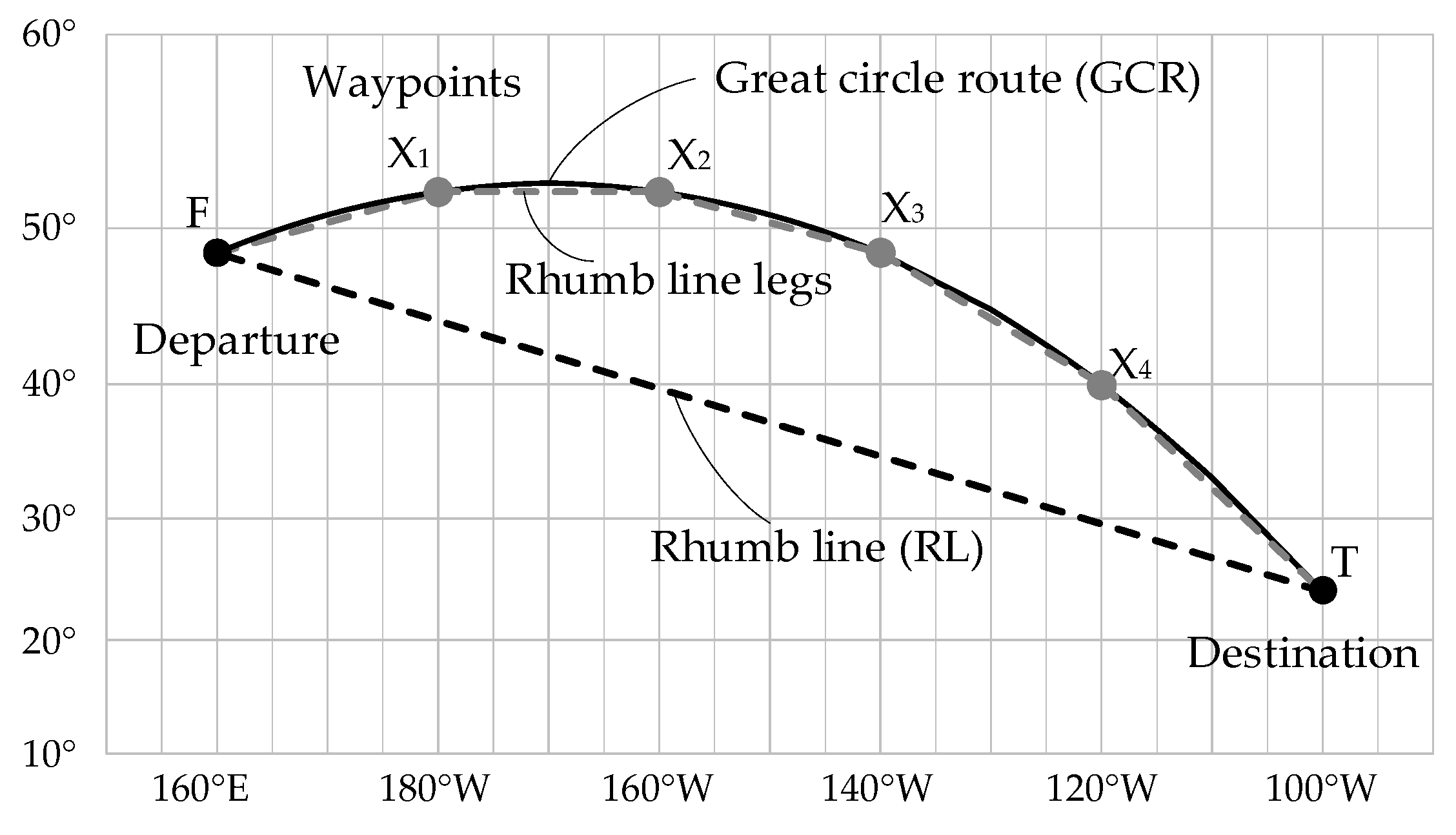
:1. Introduction
2. Great Circle Route-Related Formulae
2.1. Great Circle Distance and Initial Course Angle
2.2. Rhumb Line Course and Distance
2.3. Waypoint at a Given Longitude
2.4. Remaining Benefit of the GCR
3. Optimization Method for the Waypoints on the GCR based on the Genetic Algorithm
3.1. Population Initialization
3.2. Fitness Evaluation
3.3. Survivor Selection
3.4. Operator Reproduction
3.5. Population Update and Termination
4. Evaluation Method for the Number of Waypoints Based on Fuzzy Logic
4.1. Fuzzification
4.2. Fuzzy Logic Operators and Defuzzification
5. Example Demonstration
5.1. Example Demonstration for the GA Method
5.2. Example Demonstration for the FL Method
6. Conclusions
Author Contributions
Funding
Institutional Review Board Statement
Informed Consent Statement
Data Availability Statement
Conflicts of Interest
References
- Bowditch, N. The American Practical Navigator; 2002 Bicentennial Edition; National Imagery and Mapping Agency: Bethesda, MD, USA, 2002. [Google Scholar]
- Cutler, T.J. Dutton’s Nautical Navigation, 15th ed.; Naval Institute Press: Annapolis, MD, USA, 2004. [Google Scholar]
- Royal Navy. Admiralty Manual of Navigation: The Principles of Navigation, 10th ed.; Nautical Institute: London, UK, 2008. [Google Scholar]
- Holm, R.J. Great Circle Waypoints for Inertial Equipped Aircraft. Navigation 1972, 19, 191–194. [Google Scholar] [CrossRef]
- Chen, C.L.; Hsu, T.P.; Chang, J.R. A Novel Approach to Great Circle Sailings: The Great Circle Equation. J. Navig. 2004, 57, 311–319. [Google Scholar] [CrossRef]
- Baric, M.; Brčić, D.; Kosor, M.; Jelic, R. An Axiom of True Courses Calculation in Great Circle Navigation. J. Mar. Sci. Eng. 2021, 9, 603. [Google Scholar] [CrossRef]
- Chen, C.L.; Liu, P.F.; Gong, W.T. A Simple Approach to Great Circle Sailing: The COFI Method. J. Navig. 2014, 67, 403–418. [Google Scholar] [CrossRef]
- Jofeh, M.L. The Analysis of Great-circle Tracks. J. Navig. 1981, 34, 148–149. [Google Scholar] [CrossRef]
- Miller, A.R.; Moskowitz, I.S.; Simmen, J. Traveling on the Curved Earth. Navigation 1991, 38, 71–78. [Google Scholar] [CrossRef]
- Tseng, W.K.; Lee, H.S. The Vector Function for Distance Travelled in Great Circle Navigation. J. Navig. 2007, 60, 158–163. [Google Scholar] [CrossRef]
- Nastro, V.; Tancredi, U. Great Circle Navigation with Vectorial Methods. J. Navig. 2010, 63, 557–563. [Google Scholar] [CrossRef]
- Tseng, W.K.; Chang, W.J. Analogues between 2D Linear Equations and Great Circle Sailing. J. Navig. 2014, 67, 101–112. [Google Scholar] [CrossRef]
- Earle, M.A. Vector Solutions for Great Circle Navigation. J. Navig. 2005, 58, 451–457. [Google Scholar] [CrossRef]
- Chen, C.L. A Systematic Approach for Solving the Great Circle Track Problems Based on Vector Algebra. Pol. Marit. Res. 2016, 23, 3–13. [Google Scholar] [CrossRef]
- Chen, C.L.; Hsieh, T.H.; Hsu, T.P. A Novel Approach to Solve the Great Circle Track Based on Rotation Transformation. J. Mar. Sci. Technol.-Taiwan 2015, 23, 13–20. [Google Scholar] [CrossRef]
- Hsu, T.P.; Chen, C.L.; Hsieh, T.H. A Graphical Method for Great Circle Routes. Pol. Marit. Res. 2017, 24, 12–21. [Google Scholar] [CrossRef]
- Levin, D.Z. Which Way Is Jerusalem? Which Way Is Mecca? The Direction-Facing Problem in Religion and Geography. J. Geogr. Sci. 2002, 101, 27–37. [Google Scholar] [CrossRef]
- Murray, S. Which Way Is Jerusalem? Navigating on a Spheroid. Coll. Math. J. 2007, 38, 96–105. [Google Scholar] [CrossRef]
- Hsu, T.P.; Hsieh, T.H. Evaluation and Execution of Great Elliptic Sailing. J. Navig. 2017, 70, 1023–1040. [Google Scholar] [CrossRef]
- Tsou, M.C.; Kao, S.L.; Su, C.M. Decision Support from Genetic Algorithms for Ship Collision Avoidance Route Planning and Alerts. J. Navig. 2010, 63, 167–182. [Google Scholar] [CrossRef]
- Tsou, M.C.; Hsueh, C.K. The Study of Ship Collision Avoidance Route Planning by Ant Colony Algorithm. J. Mar. Sci. Technol.-Taiwan 2010, 18, 16. [Google Scholar] [CrossRef]
- Mao, W.; Rychlik, I.; Wallin, J.; Storhaug, G. Statistical Models for the Speed Prediction of a Container Ship. Ocean Eng. 2016, 126, 152–162. [Google Scholar] [CrossRef]
- Vettor, R.; Guedes Soares, C. Development of a Ship Weather Routing System. Ocean Eng. 2016, 123, 1–14. [Google Scholar] [CrossRef]
- Wang, K.; Yan, X.; Yuan, Y.; Li, F. Real-Time Optimization of Ship Energy Efficiency Based on the Prediction Technology of Working Condition. Transp. Res. Part D Transp. Environ. 2016, 46, 81–93. [Google Scholar] [CrossRef]
- Lee, S.M.; Roh, M.I.; Kim, K.S.; Jung, H.; Park, J.J. Method for a Simultaneous Determination of the Path and the Speed for Ship Route Planning Problems. Ocean Eng. 2018, 157, 301–312. [Google Scholar] [CrossRef]
- Wang, L.; Zhang, Z.; Zhu, Q.; Ma, S. Ship Route Planning Based on Double-Cycling Genetic Algorithm Considering Ship Maneuverability Constraint. IEEE Access 2020, 8, 190746–190759. [Google Scholar] [CrossRef]
- Zhao, W.; Wang, Y.; Zhang, Z.; Wang, H. Multicriteria Ship Route Planning Method Based on Improved Particle Swarm Optimization–Genetic Algorithm. J. Mar. Sci. Eng. 2021, 9, 357. [Google Scholar] [CrossRef]
- Zhang, D.; Zhang, Y.; Zhang, C. Data Mining Approach for Automatic Ship-Route Design for Coastal Seas Using AIS Trajectory Clustering Analysis. Ocean Eng. 2021, 236, 109535. [Google Scholar] [CrossRef]
- Earle, M.A. Sphere to Spheroid Comparisons. J. Navig. 2006, 59, 491–496. [Google Scholar] [CrossRef]
- Pallikaris, A.; Latsas, G. New Algorithm for Great Elliptic Sailing (GES). J. Navig. 2009, 62, 493–507. [Google Scholar] [CrossRef]
- Earle, M.A. Accurate Harmonic Series for Inverse and Direct Solutions for the Great Ellipse. J. Navig. 2011, 64, 557–570. [Google Scholar] [CrossRef]
- Sjöberg, L.E. Solutions to the Direct and Inverse Navigation Problems on the Great Ellipse. J. Geod. Sci. 2012, 2, 200–205. [Google Scholar] [CrossRef]
- Bennett, G.G. Practical Rhumb Line Calculations on the Spheroid. J. Navig. 1996, 49, 112–119. [Google Scholar] [CrossRef]
- Williams, R. The Great Ellipse on the Surface of the Spheroid. J. Navig. 1996, 49, 229–234. [Google Scholar] [CrossRef]
- Holland, J. Adaptation in Natural and Artificial Systems; University of Michigan: Ann Arbor, MI, USA, 1975. [Google Scholar]
- Golberg, D.E. Genetic Algorithms in Search, Optimization and Machine Learning; Addion Wesley: Boston, MA, USA, 1989. [Google Scholar]
- Baker, J.E. Reducing Bias and Inefficiency in the Selection Algorithm. In Proceedings of the Second International Conference on Genetic Algorithms, Hillsdale, NJ, USA, 28–31 July 1987; pp. 14–21. [Google Scholar]
- Zadeh, L.A. Fuzzy Sets. Inf. Control 1965, 8, 338–353. [Google Scholar] [CrossRef]
- Zadeh, L.A. Fuzzy Logic. Computer 1988, 21, 83–93. [Google Scholar] [CrossRef]
- Mamdani, E.H. Applications of Fuzzy Algorithms for Control of Simple Dynamic Plant. Proc. IEE 1974, 121, 1585–1588. [Google Scholar] [CrossRef]


| n | Low | Medium | High | |
|---|---|---|---|---|
| RB | ||||
| Lower | stop | continue | continue | |
| Medium | stop | stop | continue | |
| Higher | stop | stop | continue | |
| Number of Waypoints | Number of Iterations | RB (nm) | ||
|---|---|---|---|---|
| 55 | 57.39 | X1 (45°09.6′ N, 178°03.6′ W) | 98.39 | |
| 197 | 38.42 | X1 (45°03.6′ N, 159°05.4′ W) | 44.32 | |
| 76.46 | X2 (41°57.0′ N, 162°52.8′ E) | |||
| 248 | 28.91 | X1 (43°48.0′ N, 149°34.8′ W) | 25.01 | |
| 57.42 | X2 (45°09.0′ N, 178°04.8′ W) | |||
| 86.02 | X3 (38°54.6′ N, 153°18.6′ E) | |||
| 305 | 23.20 | X1 (42°37.2′ N, 143°52.2′ W) | 16.02 | |
| 46.01 | X2 (45°28.8′ N, 166°40.2′ W) | |||
| 68.81 | X3 (43°39.6′ N, 170°31.8′ E) | |||
| 91.82 | X4 (36°30.6′ N, 147°31.2′ E) | |||
| 330 | 19.39 | X1 (41°38.4′ N, 140°03.0′ W) | 11.13 | |
| 38.41 | X2 (45°03.6′ N, 159°04.2′ W) | |||
| 57.40 | X3 (45°09.0′ N, 178°04.2′ W) | |||
| 76.41 | X4 (41°57.6′ N, 162°55.2′ E) | |||
| 95.74 | X5 (34°38.4′ N, 143°36.0′ E) |
| Route | Departure (F) | Destination (T) | Method | n | RB |
|---|---|---|---|---|---|
| 1 | Yokohama (35°27.0′ N, 139°38.0′ E) | San Francisco (34°00.0′ N, 120°40.0′ W) | GA LBM | 4 4 | 10.84 13.83 |
| 2 | Busan (35°07.0′ N, 129°02.0′ E) | Seattle (47°42.0′ N, 122°22.0′ W) | GA LBM | 5 6 | 11.34 10.80 |
| 3 | Shanghai (31°23.0′ N, 121°30.0′ E) | Vancouver (49°14.0′ N, 123°11.0′ W) | GA LBM | 5 6 | 13.78 12.99 |
| 4 | New York (40°43.0′ N, 74°00.0′ W) | London (51°30.0′ N, 0°05.0′ W) | GA LBM | 2 3 | 13.67 7.69 |
| 5 | Los Angeles (33°43.0′ N, 118°17.0′ W) | Shanghai (31°23.0′ N, 121°30.0′ E) | GA LBM | 5 6 | 14.34 14.08 |
| n | Lower | Medium | Higher | RB | Low | Medium | High | Rule (n/RB) | Result |
|---|---|---|---|---|---|---|---|---|---|
| 1 | 1 | 0 | 0 | 98.39 | 0 | 0 | 1 | Lower/High | Continue |
| 2 | 0.75 | 0 | 0 | 44.32 | 0 | 0 | 1 | Lower/High | Continue |
| 3 | 0.50 | 0.17 | 0 | 25.01 | 0 | 0.28 | 0.29 | Lower/High | Continue |
| 4 | 0.25 | 0.33 | 0 | 16.02 | 0.14 | 0.43 | 0 | Medium/Medium | Stop |
Disclaimer/Publisher’s Note: The statements, opinions and data contained in all publications are solely those of the individual author(s) and contributor(s) and not of MDPI and/or the editor(s). MDPI and/or the editor(s) disclaim responsibility for any injury to people or property resulting from any ideas, methods, instructions or products referred to in the content. |
© 2023 by the authors. Licensee MDPI, Basel, Switzerland. This article is an open access article distributed under the terms and conditions of the Creative Commons Attribution (CC BY) license (https://creativecommons.org/licenses/by/4.0/).
Share and Cite
Hsieh, T.-H.; Meng, Q.; Han, B.; Wang, S.; Wu, X. Optimization of Waypoints on the Great Circle Route Based on Genetic Algorithm and Fuzzy Logic. J. Mar. Sci. Eng. 2023, 11, 358. https://doi.org/10.3390/jmse11020358
Hsieh T-H, Meng Q, Han B, Wang S, Wu X. Optimization of Waypoints on the Great Circle Route Based on Genetic Algorithm and Fuzzy Logic. Journal of Marine Science and Engineering. 2023; 11(2):358. https://doi.org/10.3390/jmse11020358
Chicago/Turabian StyleHsieh, Tsung-Hsuan, Qian Meng, Bing Han, Shengzheng Wang, and Xuezhen Wu. 2023. "Optimization of Waypoints on the Great Circle Route Based on Genetic Algorithm and Fuzzy Logic" Journal of Marine Science and Engineering 11, no. 2: 358. https://doi.org/10.3390/jmse11020358