Abstract
Underwater torpedoes have become a serious threat to ocean liners and warships, and the interception against attacking torpedoes is always the hotspot in marine engineering. To simulate the underwater torpedo interception by a high velocity projectile, this work numerically deals with the process of projectile water entry and sequent penetration into underwater aluminum shells, whereby conical and ogival nose projectiles are comparatively studied. With the arbitrary Lagrange–Euler (ALE) algorithm adopted to describe fluid medium, the projectile water entry model is developed and validated against the test data. Similarly, the penetration model validation is made by modeling a tungsten ball perforation on an aluminum plate. Covered by water fluid, the air-backed aluminum shell is utilized to simulate an underwater torpedo subjected to projectile impact. The numerical predictions of underwater penetration reveal that ogival nose projectiles have a superior performance in underwater motion and perforation while conical nose counterparts deteriorate the shell targets more severely. For 20 cm, 40 cm and 60 cm underwater depth scenarios, a numerical prediction suggests that the energy consumed by water is proportional to the water depth, meanwhile aluminum shell perforation absorbs almost the identical projectile kinetic energy. Such findings may shed some light on the nose shape optimization design of high velocity projectile intercepting underwater torpedoes.
1. Introduction
Oceans cover about 70% of the Earth’s surface, the utilization of marine resources, as well as marine trade routes are key interests for all coastal nations. Due to increasing frequency of marine military activities, ocean liners and warships are potentially under the threat of torpedoes [1]. The idea of a torpedo interception by a high velocity projectile was proposed, including advanced point direct interception and head-on interception [2]. As a hard kill method of underwater defense for surface warships, the high velocity projectile interception can be regarded as the last barrier against an attacking torpedo [3]. The interception modes include torpedo shell perforation and torpedo warhead impact detonation. The former torpedo shell damage may destroy its control system and power system [4] while the latter case aims to eliminate the explosive threat. Since torpedo functional destruction can be realized more easily via shell perforation, an air-backed torpedo shell subjected to high velocity projectile impact underwater is of interest.
So far, there are few studies focusing on deteriorating torpedoes beneath the ocean surface. Dozens of research fields have relevancy to torpedo injuries in water, including the kinetic energy penetration of a thin panel against the kinetic energy entity, water entry of high-speed projectiles and damage to underwater shells influenced by shock waves. These studies lay the foundation for the deterioration of underwater torpedoes. Liu et al. [5] experimentally studied the early responses of an air-backed plate subjected to underwater explosions, while Zhang et al. [6] numerically investigated air-backed plates against multiple underwater explosions. The pressure curve associated with cavitation has been analyzed, and the damage mechanism of an air-backed steel plate is the shock-induced bending and biaxial tension. Li et al. [7] studied the damage effect of a 12.7 mm super-cavitating projectile penetrating a typical underwater target shell, implying the impact effect of water medium is less than 2% of that by the kinetic energy penetration. The surface of the target exhibits an obvious concave deformation which bends less as the projectile velocity increases.
The projectile water entry area also attracted researchers to figure out the projectile motion characteristics and resistance mechanisms [8,9]. Zhang et al. [10,11] conducted experiments on different nose shaped projectiles entering the water at high speed, suggesting the flat nose projectile has a good hydro-ballistic stability in the water, while the truncated-ogival and ogival nose projectiles deflect during water entry. The water entry process is characterized with a fluid motion and is usually numerically investigated with CFD, e.g., the shear stress transport (SST) k-ω turbulence model [1,12], Reynolds-averaged Navier–Stokes (RANS) method [13], which successfully describe the water cavitation. Furthermore, the fluid-structure interaction between the projectile and water can also be modeled by a finite element method [14]. For example, Wei et al. [15] investigated the cavity evolution of an MK25 torpedo entering the water by a simulation model via LS-DYNA solver.
Although, the projectile water entry process and underwater plate damage evaluations have been analyzed, studies combining projectile water entry and sequent penetration into an air-backed shell still lack. To evaluate the high velocity projectile interception against an underwater torpedo in Figure 1, a simulation is developed with an air-backed aluminum shell against underwater projectile impact. The structure of this work is outlined as follows. The introduction of a fluid-structure interaction algorithm, as well as constitutive models involved in simulation is comprehensively deduced in Section 2. The sequent validations of water entry and aluminum plate penetration models are performed in Section 3. Furthermore, Section 4 gives the numerical predictions of underwater air-backed aluminum shells subjected to projectile impact with ogival and conical nose shapes whereby the effects of the nose shape effect and underwater depth on the cavity profile and energy consumption are analyzed. Finally, conclusive remarks are drawn in Section 5.
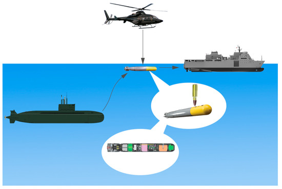
Figure 1.
Torpedo interception by high speed projectile penetration.
2. Multiphysics Modeling
2.1. Fluid-Structure Interaction Algorithm
The impact dynamic response usually causes a large mesh deformation in fluid regions during water entry simulation, the multi-medium arbitrary Lagrange–Euler (ALE) algorithm is adopted herein for the fluid medium modeling to avoid such numerical problems. With the Lagrange algorithm for structural boundary motion, the ALE algorithm can follow the motivation tracks of fluid micro-bodies. Combining the background Euler mesh, a ALE algorithm reconstitutes the body position appropriately during the solving progress. It is believed that modeling the water region and the air region with the ALE algorithm tends to give reasonable results in water entry numerical simulation [16,17].
The nonlinear governing equations of the ALE algorithm include the mass conservation equation, momentum conservation equation and energy conservation equation [18,19,20], which can be expressed as:
where is the fluid density, is time, is the fluid flowing velocity, is the Euler system coordinate, represents the stress tensor, is the body force acting on fluid, is specific total energy, is the material relative velocity with subscript i and j denoting coordinates.
2.2. Material Constitutive Models
In numerical simulation, the materials are described by constitutive laws as well as equations of state (EOS). In this work, water and air fluids are modeled with null material, while the Johnson–Cook (JC) failure criterion is used for metal materials, i.e., projectile and shell, whereas equations of states of both fluids and metals follow the Grüneisen model.
Fluid mediums are modeled by a null constitutive equation. It is an equation of state that could be calculated without a deviatoric stress term. Furthermore, it allows erosion in tension and compression occurs in mediums. Viscosity is an option that can be defined when it is of necessity. If a viscosity is defined, the viscous stress can be written in this form:
where is the dynamic viscosity of the material and it should be a non-zero constant here. is the deviatoric strain rate, and is the viscous stress produced in the material.
The materials of the projectile and the target are metal, so both of them are modeled by the Johnson–Cook constitutive equation for its wide adoption in the metal impact engineering simulation. JC is a visco-plastic material model relying on strain rate and temperature, which is suitable for problems whose strain rates vary over a large range. The JC model expresses the flow stress with the following form [21]:
where is the effective stress, is the effective plastic strain, is the normalized effective plastic strain rate, typically to strain rate of 1.0 s−1, is the work hardening exponent, and , , are constants determined by calibration.
The expression of the Grüneisen equation of state under compression can be written as [20,22]:
where is the pressure, is the density of the material in front of the wave surface, , and is the density of the material behind the wave surface, denotes the internal energy in unit volume. , , are the non-dimensional coefficients of the slope of the curve, is the Grüneisen parameter at the ambient condition, and is the unitless first order volume correction to the constant . is the intercept of the curve in velocity unit, where is the magnitude of velocity of the shock wave, is the magnitude of velocity of mass point of the material behind the wave front surface. The connection between and can be written in the follow equation:
Under expansion:
3. Numerical Model Validation
3.1. Projectile Water Entry Model
Recently, Wang et al. [23] experimentally studied the vertical water entry process of different nose shaped projectiles, whereby the water cavitation evolution and projectile motions are analyzed in detail. The water entry process of conical projectiles with a 90 nose angle from [23] is modeled with the foregoing ALE algorithm. The validated model may be further applied to the water entry and underwater motion simulations, prior to the projectile impacting the torpedo shell during interception.
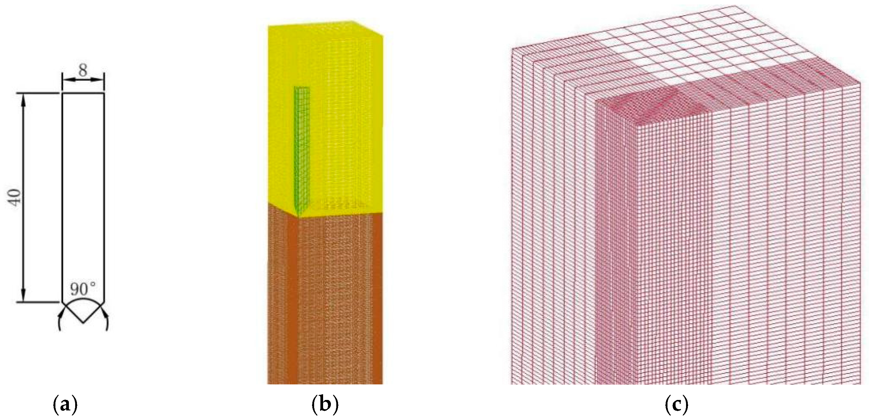
Fluid-structure interaction simulation of a projectile entering water from the air is performed in a rectangular space filled with fluids, where the upper air region has a 6 cm thickness and the depth of the water region is 36 cm. The constitutive parameters in LS-DYNA for air and water are listed in Table 1 and Table 2, according to [20], where dynamic viscosity μ and pressure cutoff Pc are null parameters. The 90 nose angle conical projectile has a diameter of 8 mm, and a total length of 44 mm, as shown in Figure 2a. With a 2.8 m/s striking velocity, the projectile is defined as a rigid body allowing an appreciable reduction of the computational cost. With symmetric boundaries, the quarter model of the projectile water entry model is developed with non-reflection boundaries, as shown in Figure 2b. The center zone affected by the water entry process was meshed with finer elements, 0.5 mm × 0.5 mm × 0.5 mm in Figure 2c. The air region is meshed with 94k elements while the water region has 564k elements, as listed in Table 3. Finally, the whole model is applied with a downwards gravity of 9.8 m/s2.

Table 1.
Material parameters of air (units: cm-g-µs).
Table 2.
Material parameters of water (units: cm-g-µs).

Figure 2.
The schematic diagrams of the fluid-structure interaction model. (a) 90 conical-shape nose projectile(unit: mm); (b) meshes of the fluid regions; (c) water region meshes.
Table 3.
Element numbers for each component of the fluid-structure interaction model.
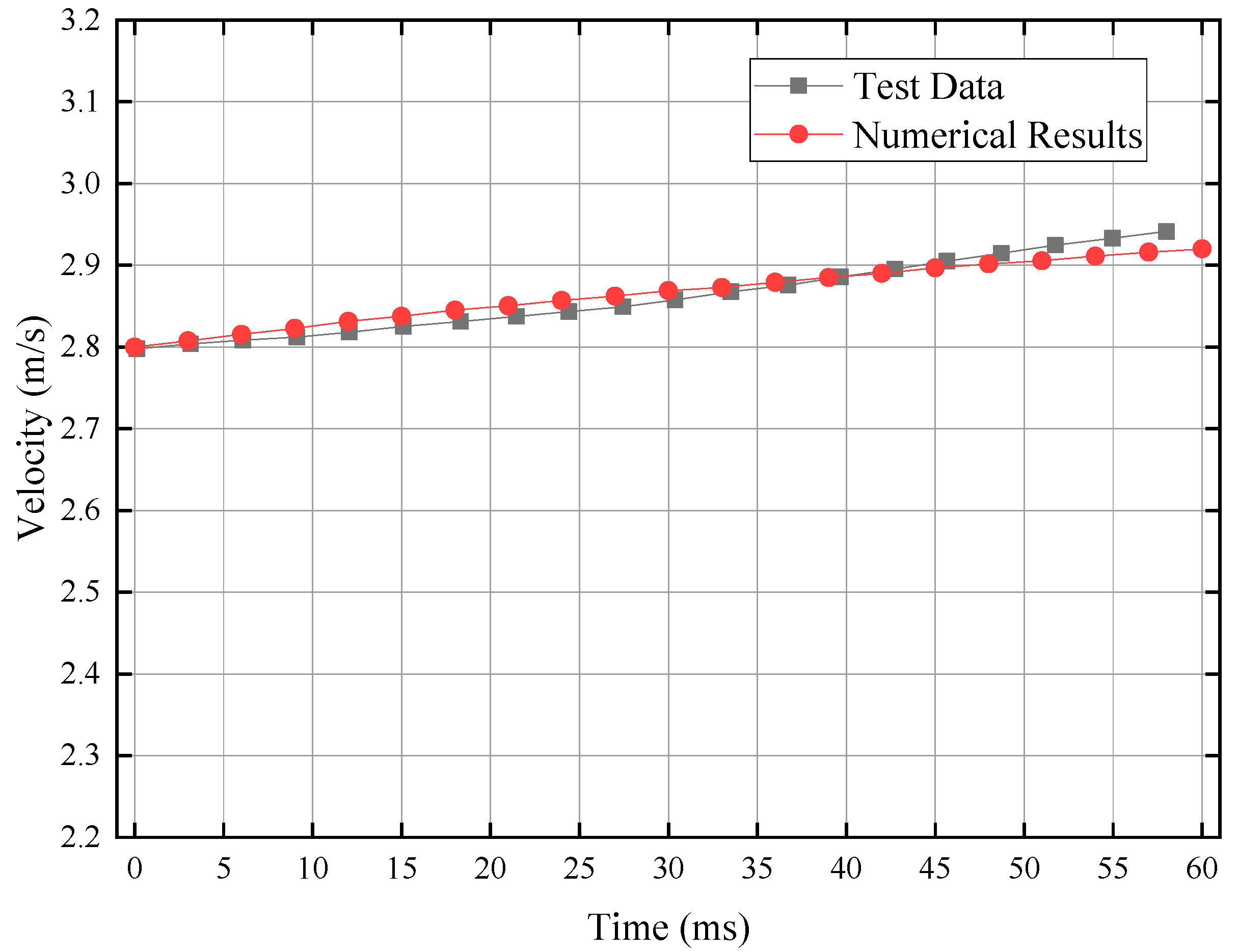
To validate the numerical method, the numerical predictions of the projectile velocity history are compared with the corresponding test data [23], as shown in Figure 3, suggesting the consistent tendency of the projectile velocity history evolution. At 55 ms, the projectile velocity of the simulation increases to 2.92 m/s, and the experimental records imply a 2.94 m/s velocity, which has only a 0.7% error.

Figure 3.
Numerical results and experiment data of the projectile velocity.
Furthermore, Figure 4 compares the evolution of the cavity shapes of the simulation, in forms of fluid density charts, with that of experimental records. Both numerical modeling and high speed test photograph images describe three distinct stages for the cavity evolution: the impact stage, the pitch-off stage, and the navigating stage. The cavity containing the projectile and the splash caused by the impact in both kinds of recordings are exhibiting the same characteristics during the stage of the projectile impacting the water surface. In the second stage, the cavity evolves into two parts and it starts to close (prior to 48.3 ms). In the third stage, the part close to the water surface shrinks and forms a jet flow pointing to the water surface, and another part remains attached to the projectile. Therefore, both the projectile velocity evolution and cavity evolution of projectile water entry and sequent underwater motion can be captured by the ALE model simulation.
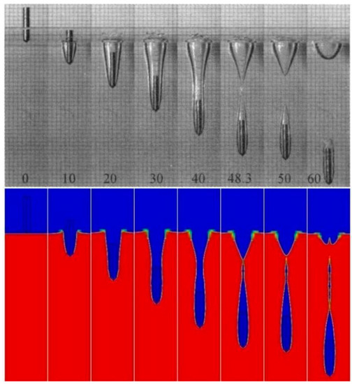
Figure 4.
Numerical results and experiment records of the cavities.
3.2. Aluminium Shell Penetration Model
Following water entry and underwater motion, the projectile is supposed to perforate the torpedo shell to realize interception. With the Lagrange algorithm, the penetration model made of aluminum alloy plate under tungsten fragment impact from [24], is developed herein for the validation. The 10 mm diameter sphere fragment made of tungsten 93 is launched with various velocities to strike the aluminum LY12CZ plate with a 8 mm thickness, whereby the ballistic limit is 306 m/s.
Both the tungsten sphere and aluminum target are meshed with 3D Solid164 elements of 0.2 mm × 0.2 mm × 0.2 mm size. The foregoing JC model is adopted for both the tungsten and aluminum metals, whereas their corresponding material parameters, defined in LS-DYNA, are listed in Table 4 and Table 5 with reference to [24], where CP is the thermal heat and Pc is the tensile pressure cutoff. An eroding algorithm is applied to both the penetrator and target to ensure the perforation destruction and avoid negative volume error.
Table 4.
Material parameters of tungsten 93 (units: cm-g-µs).
Table 5.
Material parameters of aluminum LY12CZ (units: cm-g-µs).
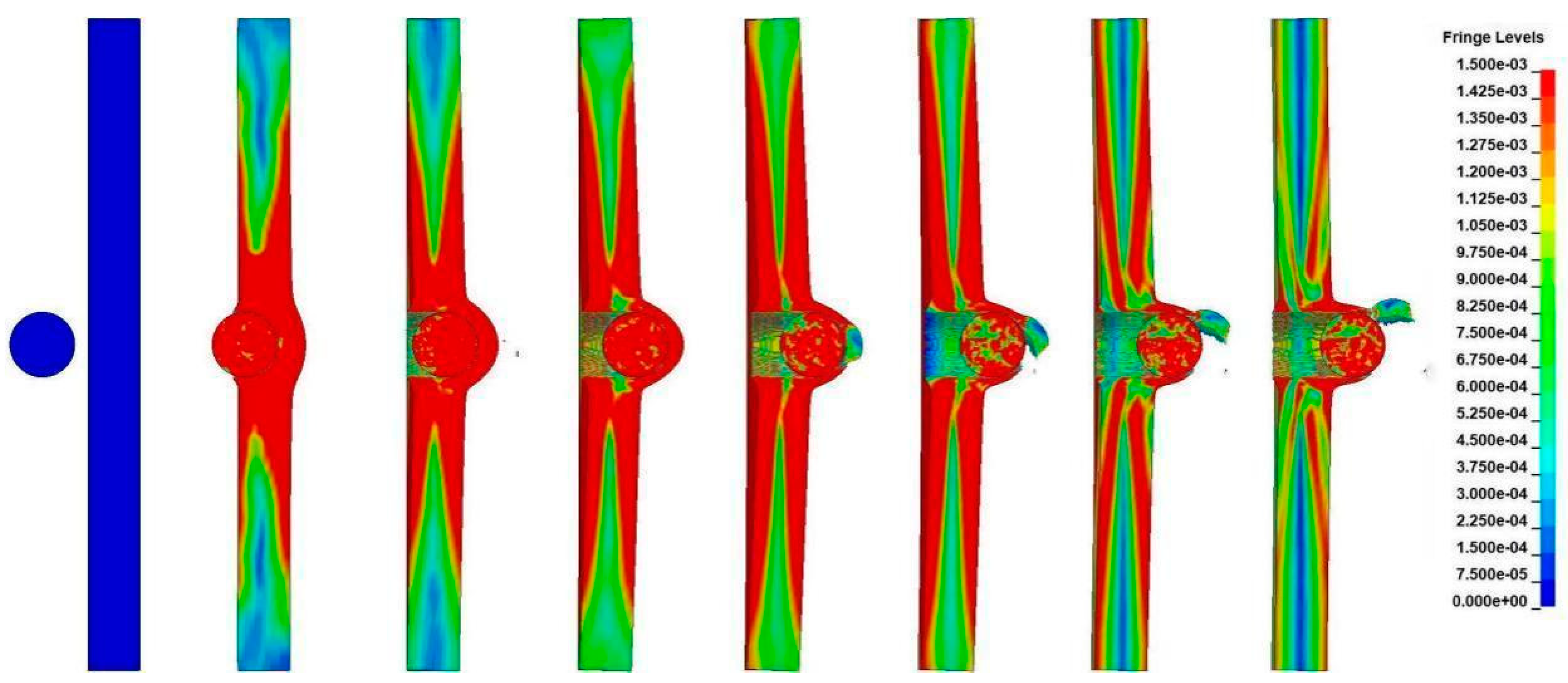
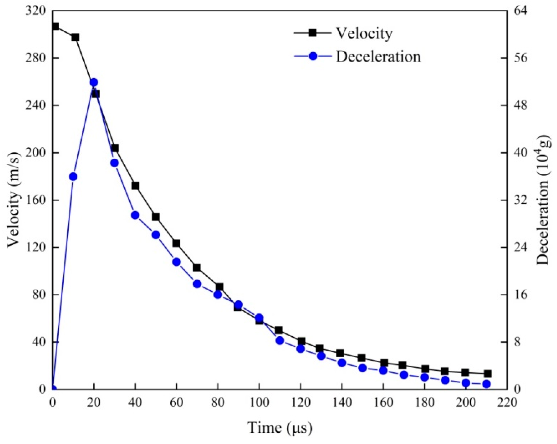
The penetration process of the spherical fragment passing through the aluminum plate is plotted in Figure 5, with every 30 μs time interval. The perforation process of the numerical simulation can be divided into two stages: tunneling and shear plugging. During tunneling, the spherical fragment movements form a smooth tunnel. The shear plugging of the aluminum plate rear surface is featured with tearing apart the damage mode matching with the typical aluminum destruction [24]. Figure 6 shows the numerical predictions of the tungsten sphere velocity evolution and deceleration history during penetration into the aluminum plate. The peak overload of about 520,000 g (gravitational acceleration) occurs at 20 μs, corresponding to the full contact of the half sphere surface with a metal target. The tearing apart of the rear surface aluminum also leads to the oscillation of deceleration curve during 80 μs to 100 μs. Following the aluminum plate perforation, the residual projectile velocity derived from numerical simulation is only about 13 m/s, which agrees well with the test data. Hence, the aluminum shell penetration model is validated, in terms of ballistic performance and damage mode.
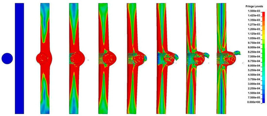
Figure 5.
Numerical results of the aluminum plate penetration process.
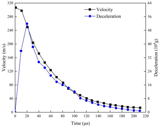
Figure 6.
Velocity and deceleration history of the tungsten ball during perforation in simulation.
4. Simulation of the Projectile Intercepting Underwater Torpedo Shells
Prior to hitting the torpedo shell, the resistance during water entry and underwater motion consumes some of the projectile’s kinetic energy, which is mainly attributed to the projectile nose shape and underwater depth. To realize an efficient torpedo interception, less energy loss during passing through water is desirable. Similarly, the perforation response of the torpedo shell also relates to the projectile nose shape. The projectile nose shape and underwater depth effects on the torpedo interception are numerically investigated.
4.1. Projectile Penetration on Underwater Air-Backed Aluminum Shells
Based on the previous validation of the ALE modeling for projectile water entry and JC model for the fragment impact aluminum plate, the high speed tungsten projectile intercepting underwater torpedo simulation can be carried out with projectile striking underwater air-backed aluminum shells. The curvature shape of the 5 mm thick aluminum shell refers to the dimension of a 533 mm heavy torpedo [25] while the interception projectile is determined as having a 30 mm shank diameter with a 800 m/s striking velocity matching an aircraft gun in an AH-64D attack helicopter [26].
Similarly, the numerical modeling of torpedo interception is built with five parts: air above the water, projectile (in the air), water (certain depth), aluminum shell (part of torpedo), and air under the shell (inside the torpedo) as given in Figure 7. The air regions and water region are described with the ALE grid while the projectile and aluminum shell are simulated with the JC model with the Lagrange algorithm.
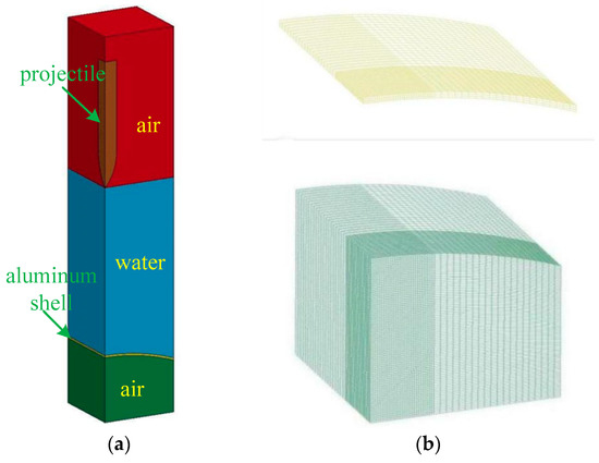
Figure 7.
The schematic diagrams of the underwater penetration model and meshes; (a) 5 different parts; (b) meshes of the aluminum shell and the air region behind the shell.
A rectangular ALE region of 9 cm × 9 cm × 46 cm was generated for the fluid modeling in Figure 7a where the air-backed aluminum shell, with a 5 mm thickness, is located at a 20 cm underwater depth. The projectile shell, as well as the fluid regions, are symmetrically constrained with non-reflection boundaries defined for the outside surfaces. The centroid zone of the fluid ALE is meshed with finer grids of 1 mm × 1 mm × 1 mm, while the shell is meshed with same element size with background ALE elements, as shown in Figure 7b. For an element size effect analysis, 0.5 mm to 2 mm length elements are compared, suggesting 1 mm size elements give relatively fast numerical results with convergence. Table 6 gives the detail numbers of each part of the underwater penetration model.
Table 6.
Element numbers for the underwater penetration model.
Twenty degrees Celsius is adopted for the torpedo interception numerical model, where the water density is 998 kg/m3 with 1.01 × 10⁻³ Pa·s dynamic viscosity, and air density is 1.205 kg/m3 with 1.81 × 10⁻⁵ Pa·s dynamic viscosity. JC parameters used for tungsten and aluminum are the same as those of the validation model, as given in Table 4 and Table 5.
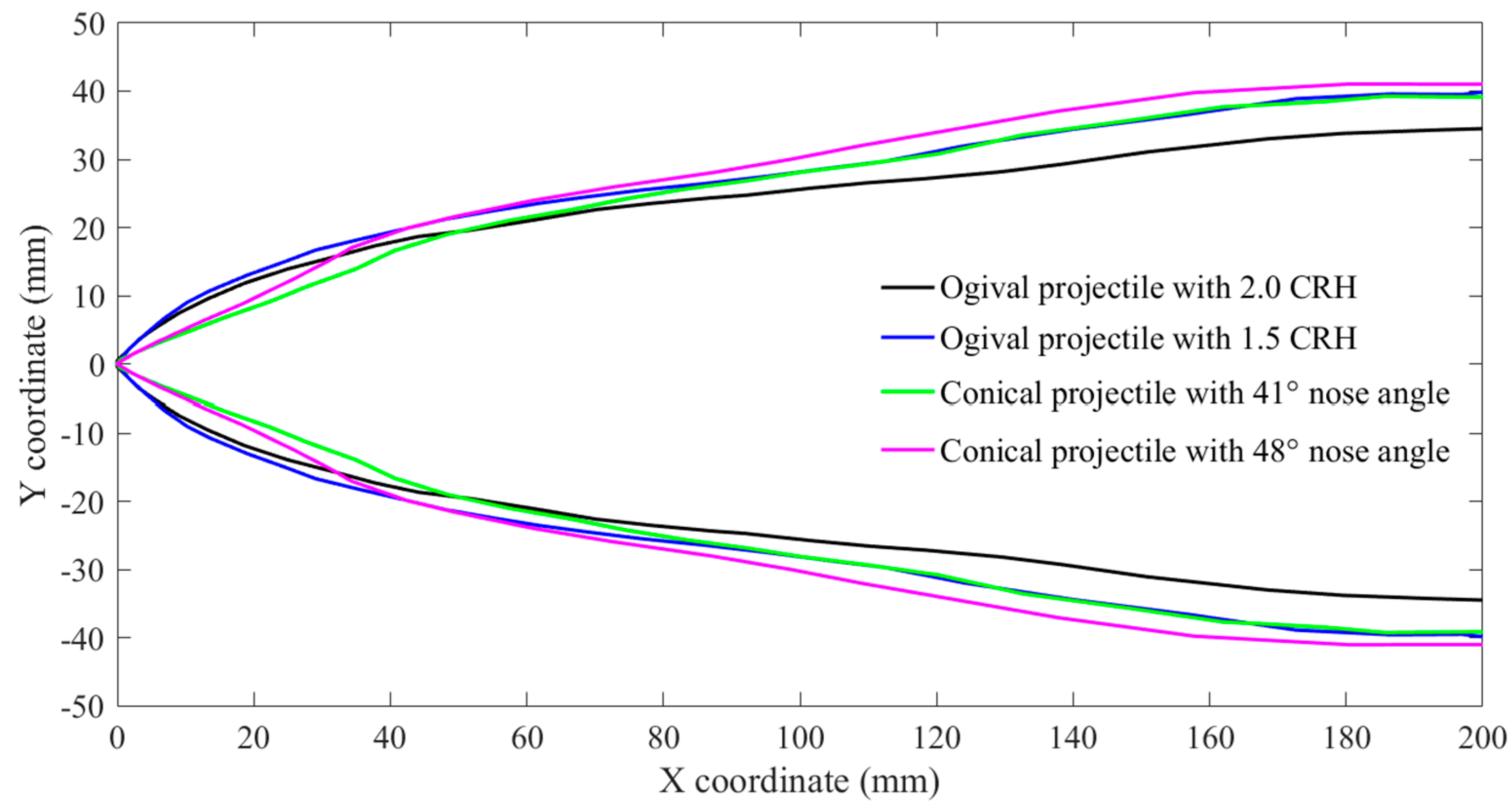
In order to study the projectile nose shape effect on the interception efficiency, typical ogival and conical nose projectiles are comparatively analyzed. Four different projectiles are used for the underwater penetration simulations, as illustrated in Figure 8, whereby the No. 1 and No. 2 projectile noses are of ogival shape with 2.0 and 1.5 CRH (caliber-radius-head) [27,28] and No. 3 and No. 4 projectiles have a conical shape with 41° and 48° nose angle. In the fluid-structure interaction algorithm, the tungsten projectile and aluminum shell interact with both the air region and the water region.
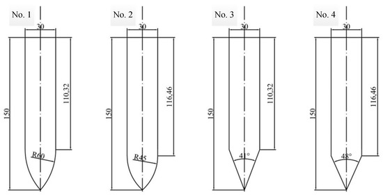
Figure 8.
Projectile shapes applied to underwater penetration simulations (dimension in millimeters).
4.2. Nose Shape Effect on the Projectile Water Entry and Underwater Motion
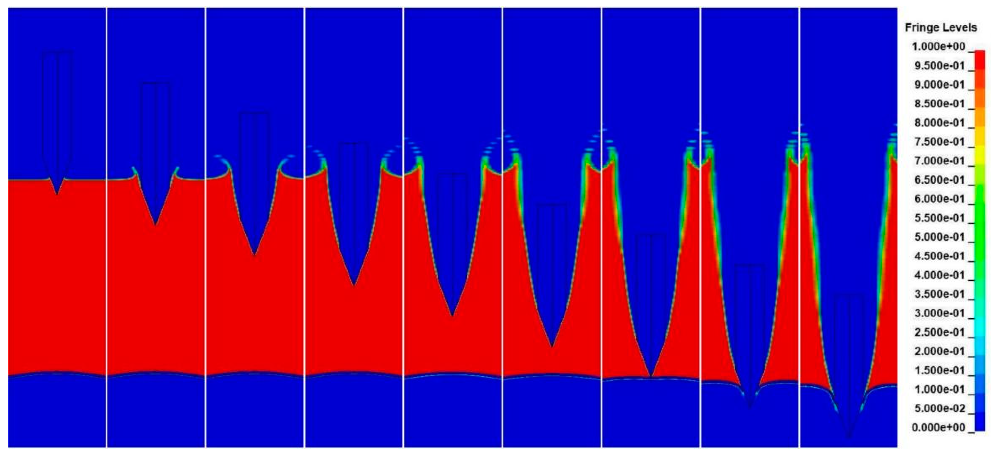
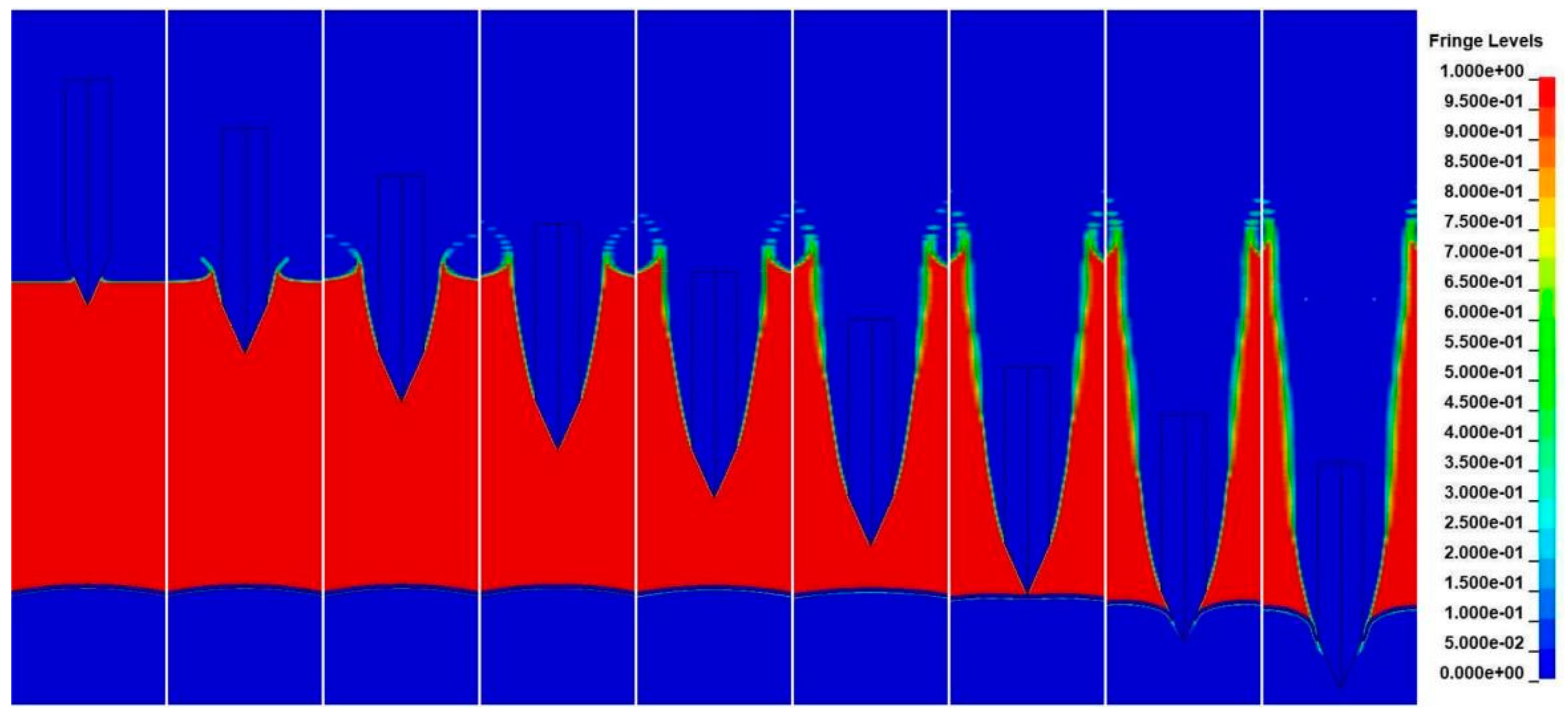
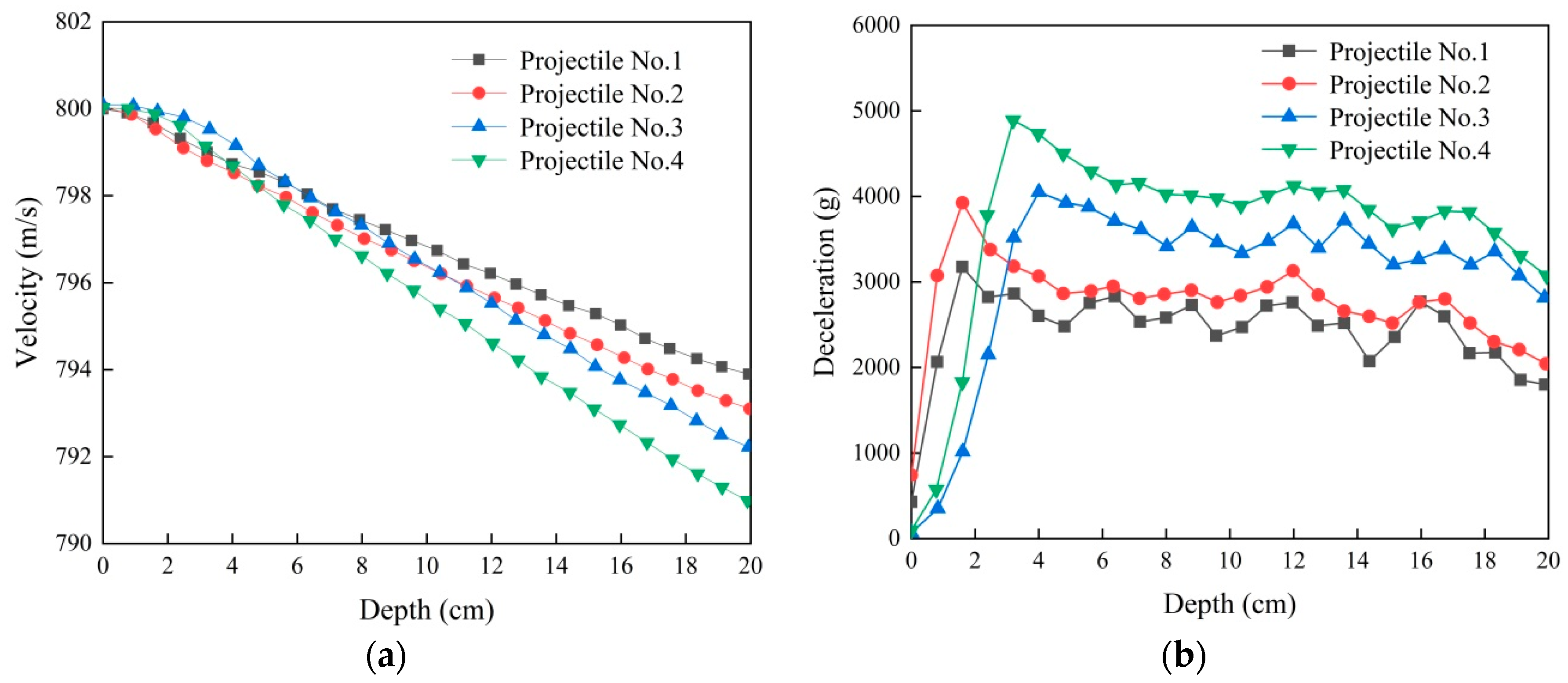
Numerical results of the ogival and conical nose shape projectiles water entry and underwater motion processes are plotted in Figure 9, Figure 10, Figure 11 and Figure 12, whereby the fluid density contour of ALE elements gives a clear visualization of water cavitation and fluid motions. The projectile enters the water by pushing the surrounding fluids away, causing a cavitation which keeps expanding due to the inertial effect. Due to the shallow underwater depth, the projectile starts to hit and tear up the aluminum shell before the cavity closure. Figure 13 shows the cavity profiles of the ogival and conical nose shape projectiles from the simulations. It is interesting to find that the ogival nose ones tend to generate less expanded cavity than their conical counterparts. Combining the velocity and deceleration histories in Figure 14, after passing through 20 cm depth water, the velocities of projectile No. 1, 2, 3, and 4 decreased to 793.94 m/s, 793.13 m/s, 792.29 m/s, and 790.96 m/s. Figure 14b illustrates the deceleration evolution of the projectile water entry under water motion. Although, a large deceleration occurs for the water entry process, a shallow water depth changed the projectile velocity, but not by much. The deceleration increases as the projectile tip enters the water with more interaction surfaces, suggesting sharper projectiles suffer less resistance for both ogival and conical shapes. Once the projectile nose fully enters the fluid, the resistant force reaches the peak, which is followed by a plateau with a slight decrease. It is notable that the ogival projectiles suffer much less water resistant force than the conical projectiles which agree well with the literature reports [14].

Figure 9.
Numerical results of projectile No.1 water entry and underwater motion.

Figure 10.
Numerical results of projectile No.2 water entry and underwater motion.
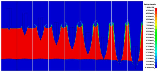
Figure 11.
Numerical results of projectile No.3 water entry and underwater motion.
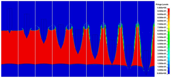
Figure 12.
Numerical results of projectile No.4 water entry and underwater motion.

Figure 13.
Cavity profiles of the different nose shape projectiles.
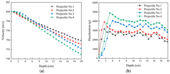
Figure 14.
Numerical results of the different nose projectile water entries and underwater motions. (a) Velocity evolution. (b) Deceleration evolution.
4.3. Nose Shape Effect on the Underwater Impact of Air-Backed Aluminum Shells
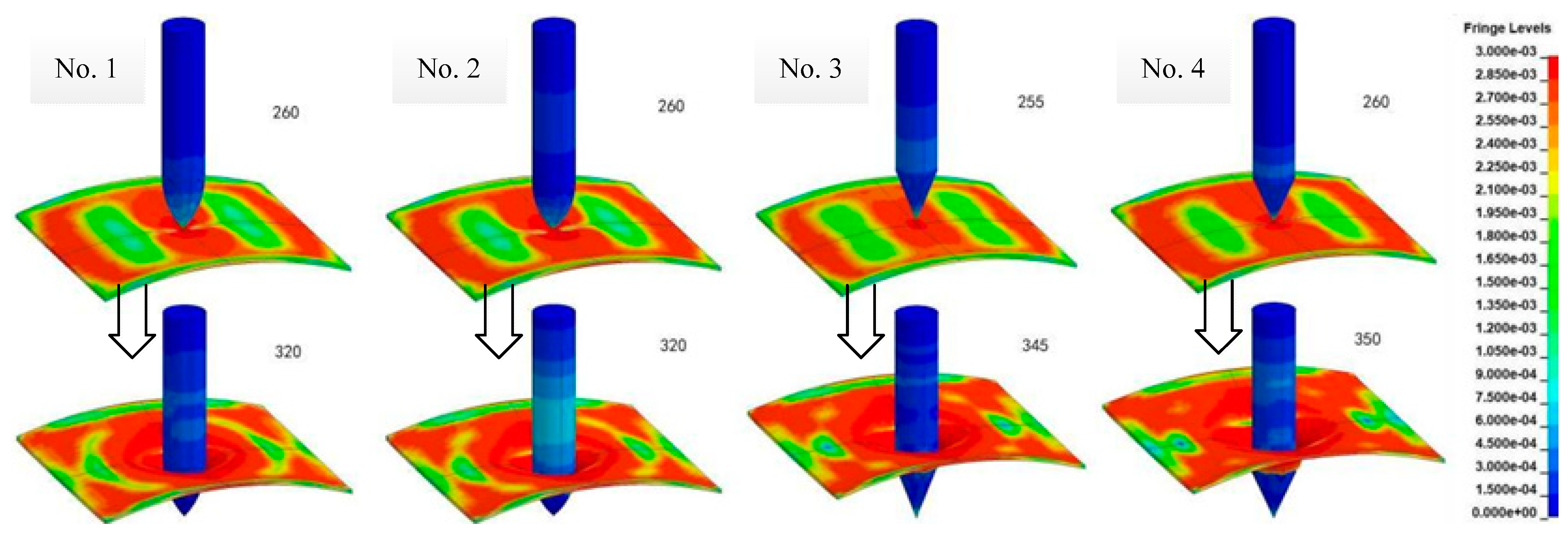
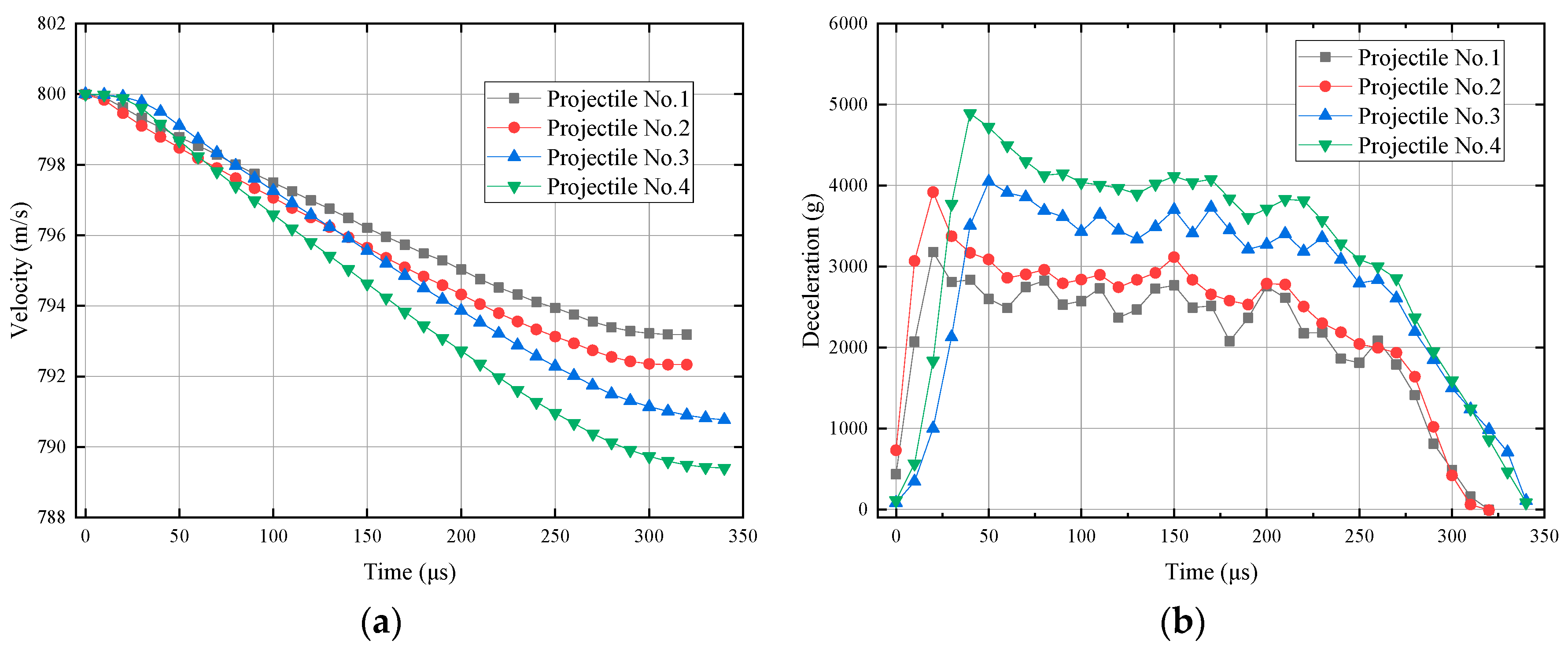
Once passing through a 20 cm depth of water, the projectile starts to impact the aluminum shell. Due to inertial effect, the water is driven by the projectile to deform the aluminum shell to some extent. At about 260 μs, in Figure 15, the shells are pushed downward with a Mises stress concentration prior to the projectile hitting the target. At 320 μs, the ogival projectiles perforates the air-backed shell with a depressed fracture at the impact location. The conical counterparts cause a more severe destruction with a higher intense stress distribution in the shell. Similarly, the projectile velocity and deceleration histories over time are plotted in Figure 16. The residual velocities of the ogival projectiles are higher than that of conical projectiles. For both the underwater motion and air-backed shell perforation, the ogival projectiles suffer less resistant force. The better shaped ones exhibit superior water navigation ability and aluminum penetration performance.

Figure 15.
Von Mises stress distribution before and after aluminum shell perforation.
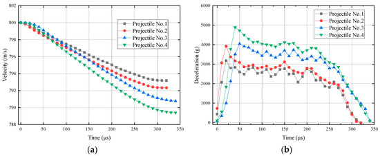
Figure 16.
Numerical simulation results of the underwater penetration. (a) velocity history; (b) deceleration history.
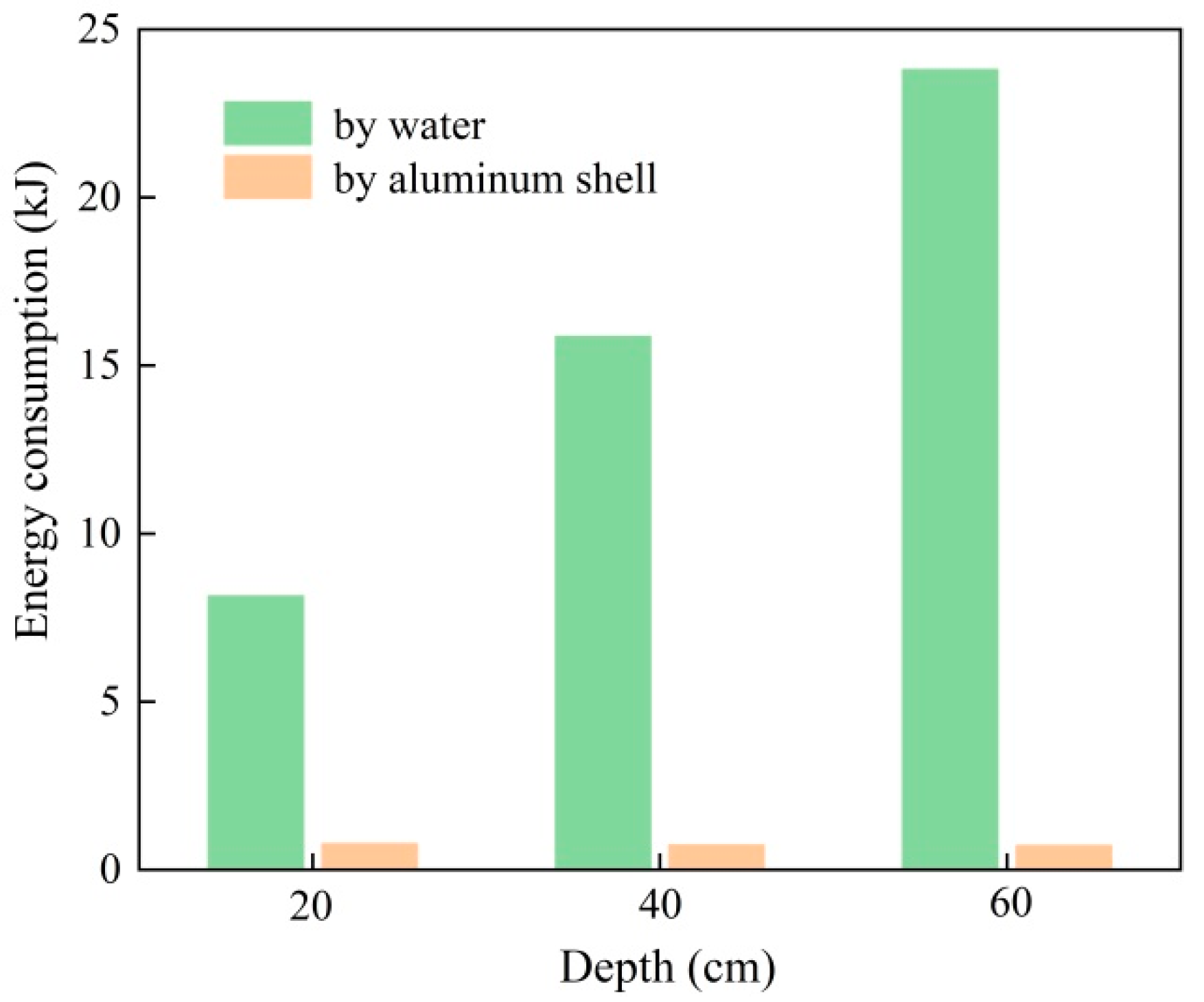
The energy consumption by the water and aluminum shell is summarized in Figure 17 and Table 7. Projectile no. 1 experiences the least amount of energy for both underwater motion region and shell perforation stage. Compared with ogival nose shape of projectile no. 1, the conical nose shape projectile No. 4 suffers higher energy loss during underwater penetration, i.e., 1.44 times kinetic energy consumption during underwater motion and 2.0 times perforation energy. For the projectiles of interest, both underwater navigation and aluminum shell perforation reveal the conical projectiles gain a larger resistance than ogival projectiles, leading to greater energy consumption.
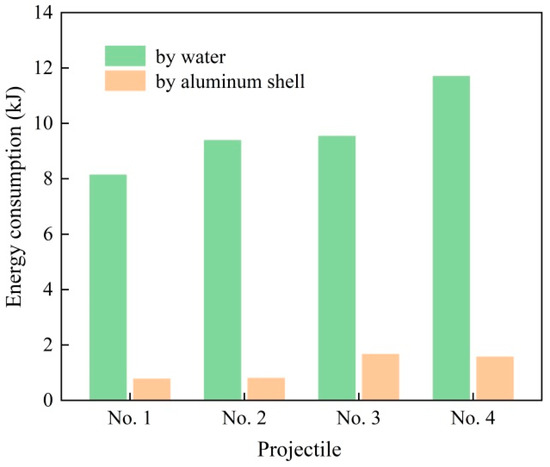
Figure 17.
Numerical results of the energy consumption during the underwater penetration.
Table 7.
Energy consumption during the underwater penetration (J).
4.4. Underwater Depth Effect Discussion
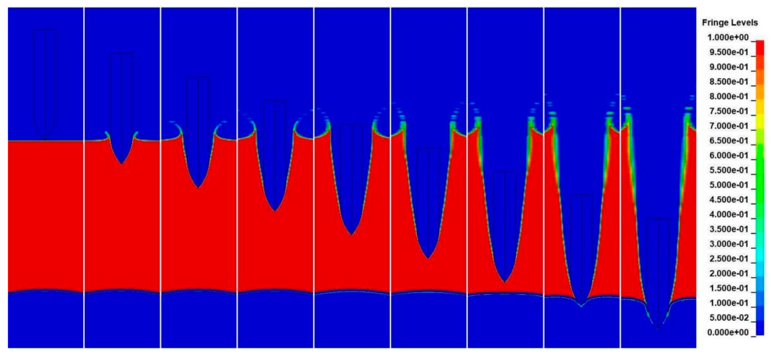
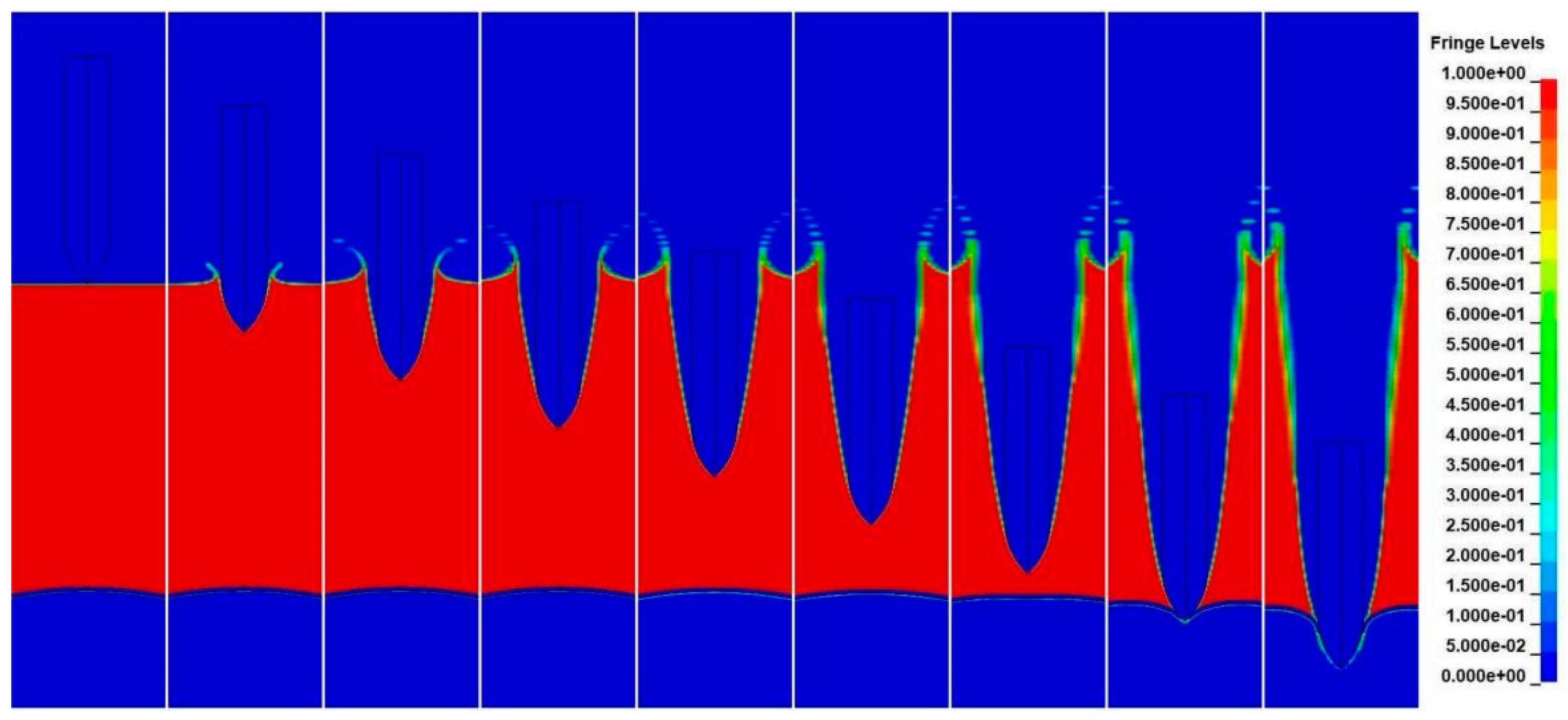
To analyze the underwater depth effect on the torpedo interception efficiency, projectile no. 1 penetration on underwater air-backed aluminum shells is further numerically studied with 40 cm and 60 cm depth underwater conditions.
Figure 18 shows the cavity profile prior to the projectile hitting the shell. It is notable that the cavity keeps expanding and no fluid goes back to cause cavity shrinkage. The cavity part near the water surface tends to expand more while less expansion occurs as the underwater depth increases. This may be due to the fact that hydrostatic pressure is proportional to the underwater depth, cavity receives less pressure confinement near the free surface.
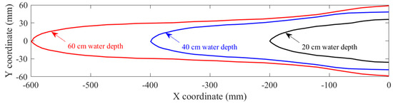
Figure 18.
Underwater depth effect on the cavity profile of projectile no. 1.
The projectile deceleration histories for different underwater depths are plotted in Figure 19, whereby the curves overlap each other before 200 μs because the projectile water entry and underwater motion are similar before the air-backed shell poses any effect. Due to the free surface of the shell, the resistance drops as the projectile goes deeper. The gradual decrease is then followed by a sudden jump when the projectile impacts the aluminum shell. Owing to the limit thickness, the resistance jump lasts for a very short period.
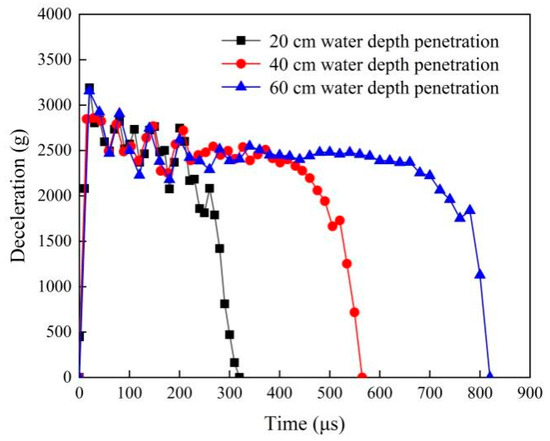
Figure 19.
Projectile deceleration histories for different underwater depths.
For different depths, water consumed energy and aluminum shell consumed energy are given in Figure 20 and Table 8. Most of the projectile energy loss is due to the water. The water related energy consumption is almost proportional to the underwater depth while the shell perforation consumed energy is approximately constant, which is identical to the typical thin wall structure perforation responses in air medium [29,30,31]. For the 2.0 CRH projectile penetration, underwater air-backed aluminum shell, the energy consumption might be achieved as:
where E is the energy absorbed during the underwater penetration, H is the underwater depth with unit meter. The best fitted equation only applies for the 30 mm shank diameter ogival nose projectile impacts the 5 mm aluminum shell with underwater depth less ranging from 20 cm to 60 cm, more experimental studies are needed to validate this empirical formula.
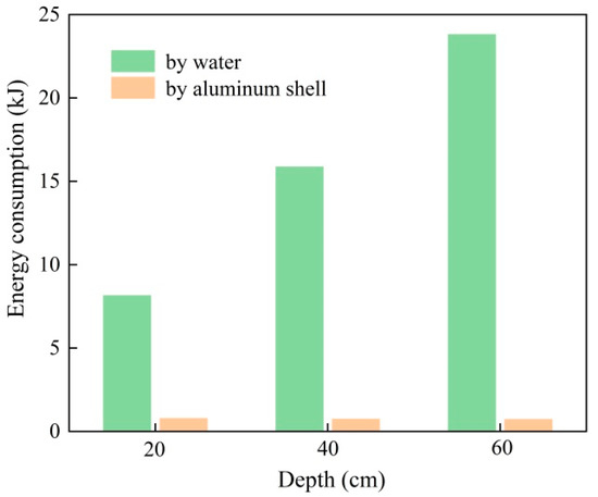
Figure 20.
Energy consumption for the different water depth underwater penetrations.
Table 8.
Energy consumption of projectile no. 1 during underwater penetration (J).
The speed of the projectile in the water drops dramatically. The penetration resistance in the water medium usually is relevant to the projectile velocity and water pressure [32,33], therefore the water resistant force F acting on projectile No. 1 is best fitted as:
where V is the projectile velocity, Dw is the current water depth, as the projectile water entry proceeds the dynamic resistance decreases, while the static resistance increases.
F = 0.072V2 + 6.924Dw
5. Conclusions
Water entry and underwater air-backed aluminum shell penetration with different nose shape projectiles are explored numerically with validated fluid-structure interaction and penetration models in this work. Extensive numerical predictions give conclusions:
- (1)
- Suffering much less water resistant force, ogival nose projectiles tend to generate less expanded cavitation than the conical counterparts;
- (2)
- Prior to the projectile hitting the aluminum shell, the water is driven by the projectile to deform the target owing to inertial effect. Ogival projectiles suffer less penetration resistance while the conical ones pose more severe damage during shell perforation;
- (3)
- For both ogival and conical nose shaped projectiles, shaper ones exhibit a superior water navigation ability and can perforate the aluminum shell more easily;
- (4)
- For both underwater motion and air-backed shell perforation, the ogival projectiles suffer less resistant force. For 20 cm depth underwater penetration, conical nose shape projectile no. 4 suffers 1.44 times kinetic energy consumption during underwater motion and 2.0 times perforation energy of energy loss of ogival nose shape projectile no. 1;
- (5)
- For shallow water depth conditions, the water related energy consumption is almost proportional to the underwater depth while the shell perforation consumed energy is approximately constant. Liner empirical formula of underwater energy consumption for projectile No. 1 is proposed as: which needs further experimental validation.
Author Contributions
Conceptualization, C.D.; Software, B.C.; Validation, X.S.; Formal analysis, C.D.; Investigation, C.P.; Data curation, C.D. and X.S.; Writing—review & editing, J.F.; Supervision, W.L. and T.Q.; Project administration, C.P.; Funding acquisition, J.F. All authors have read and agreed to the published version of the manuscript.
Funding
This research was financially supported by the National Natural Science Foundation of China (No. 11902161) and Natural Science Foundation of Hunan Province (No. 2020JJ5208). The APC was funded by the Major Science and Technology Project of Shanxi Province (No. 20201102003).
Institutional Review Board Statement
Not applicable.
Informed Consent Statement
Not applicable.
Data Availability Statement
Some or all data, models, or code that support the findings of this study are available from the corresponding author upon reasonable request.
Acknowledgments
Dacheng Gao is acknowledged for his timely help in simulation.
Conflicts of Interest
The authors declare no conflict of interest.
References
- Panciroli, R.; Pagliaroli, T.; Minak, G. On Air-Cavity Formation during Water Entry of Flexible Wedges. J. Mar. Sci. Eng. 2018, 6, 155. [Google Scholar] [CrossRef]
- Wu, B.Q.; Guan, X.C.; Guan, S.H.; Shi, J.B. A capture probability analytic model for the electromagnetic launched anti-torpedo torpedo. Def. Technol. 2022, 18, 261–270. [Google Scholar] [CrossRef]
- Li, S.; Wang, Y.; Wu, S.; Niu, W.; Yang, S.; Lan, S. Multi-body modelling and analysis of the motion platform for underwater acoustic dynamic communication. Appl. Math. Model. 2022, 109, 455–472. [Google Scholar] [CrossRef]
- Jia, Y.; Song, B.W.; Li, W.Z. Theory and Method of Intercepting Torpedo Using Rocket Depth Charges. Syst. Eng. Theory Pract. 2005, 25, 137–140. [Google Scholar]
- Liu, J.; An, F.; Wu, C.; Liao, S.; Zhou, M.; Xue, D. The Early Responses of Air-backed plate subjected to underwater explosion with aluminized explosives. Def. Technol. 2020, 16, 642–650. [Google Scholar] [CrossRef]
- Zhang, F.; Zhang, C.H.; Zhang, L.; Wang, Z.J.; Zhou, C.G. Numerical simulation of dynamic response of steel plate subjected to multiple underwater explosions. Chin. J. Ship Res. 2019, 14, 122–129. [Google Scholar]
- Li, X.; Yan, P.; Tan, B.; Qin, Y.P. Three-Phase Coupling Numerical Simulation of Underwater Penetration of Supercavitating Projectile into Target Plate. Chin. J. High Press. Phys. 2020, 34, 113–120. [Google Scholar]
- Shen, X.L.; Zhu, X.; Zhao, H.G. Experimental analysis of underwater explosion fragment penetrating characteristic base on high-speed recording device. Ship Sci. Technol. 2015, 37, 32–35. [Google Scholar]
- Hou, Y.; Huang, Z.; Chen, Z.; Guo, Z.; Xu, Y. Experimental investigations on the oblique water entry of hollow cylinders. Ocean. Eng. 2022, 266, 112800. [Google Scholar] [CrossRef]
- Zhang, W.; Guo, Z.T.; Xiao, X.K.; Wang, C. Experimental investigations on behaviors of projectile high-speed water entry. Explos. Shock. Waves 2011, 31, 579–584. [Google Scholar]
- Zhang, W.; Huang, W.; Ren, P.; Ye, N.; Li, D.C. The underwater shock wave characteristics caused by high speed horizontal water entry projectiles. J. Harbin Inst. Technol. 2016, 48, 37–41. [Google Scholar]
- Li, Q.; Lu, L. Numerical Investigations of Cavitation Nose Structure of a High-Speed Projectile Impact on Water-Entry Characteristics. J. Mar. Sci. Eng. 2020, 8, 265. [Google Scholar] [CrossRef]
- Yu, P.; Shen, C.; Zhen, C.; Tang, H.; Wang, T. Parametric Study on the Free-Fall Water Entry of a Sphere by Using the RANS Method. J. Mar. Sci. Eng. 2019, 7, 122. [Google Scholar] [CrossRef]
- Wang, S.; Soares, C. Numerical study on the water impact of 3D bodies by an explicit finite element method. Ocean. Eng. 2014, 78, 73–88. [Google Scholar] [CrossRef]
- Wei, H.L.; Zhao, J.; Xu, Z.C.; Yu, Q.D.; Li, M. Study on High-speed Water Entry Law of Trans-media Vehicle Based on Fluid Solid Coupling. Missiles Space Veh. 2020, 2, 33–37. [Google Scholar]
- Guo, Z.T. Research on Characteristics of Projectile Water Entry and Ballistic Resistance of Targets Under Different Mediums. In Amur River; Harbin Institute of Technology: Harbin, China, 2012; pp. 23–28. [Google Scholar]
- Wang, Z.; Kong, X.S.; Wu, W.G. Velocity Attenuation Characteristics of High-velocity Fragments Penetrating Liquid Tank. Acta Armamentarii 2021, 42, 167–172. [Google Scholar]
- Li, Y.L.; Wang, J.X.; Shen, X.J.; Zhou, N.; Huang, R.Y.; Rong, G. Initiation theory of shield explosive impacted by underwater explosion shock wave and its simulation. J. Vib. Shock. 2019, 38, 31–36. [Google Scholar]
- Wang, Z.; Wu, M.L.; Dai, W.L. Study on Load Characteristics of High-speed Water-entry of Large Caliber Projectile. J. Ballist. 2020, 32, 15–22. [Google Scholar]
- Wang, Z.; Wu, M.L.; Sun, Y.S.; Peng, J.H. Multi-Medium ALE Algorithm-Based Simulation of Vertical and High-Speed Water Entry of Cylinder. J. Unmanned Undersea Syst. 2020, 28, 81–88. [Google Scholar]
- Pu, B.; Wang, X.M.; Li, W.; Feng, J. Analytical Model Formulation of Steel Plate Reinforced Concrete Walls against Hard Projectile Impact. Appl. Sci. 2022, 12, 518. [Google Scholar] [CrossRef]
- Shi, H.H.; Zhou, D.; Wen, J.S.; Jia, H.X. Fluid-solid Interaction Simulation of Elastic Cylindrical Shell Penetrating Water Based on the ALE Method. J. Ballist. 2020, 32, 9–14, 46. [Google Scholar]
- Wang, R.Q.; Huang, Z.G.; Guo, Z.Q.; Chen, Z.H.; Gao, J.G.; Hou, Y. Experimental Study of Low Speed Vertical Water Entry with Different Head Shape Projectiles. J. Sichuan Ordnance 2017, 38, 45–50. [Google Scholar]
- Cao, B. An Experimental Investigation on the Equivalent Relation Between Different Armour Plates Penetrated by Fragments. J. Proj. Rocket. Missiles Guid. 2006, 26, 113–114, 117. [Google Scholar]
- Lu, X.; Wang, S.H.; Wang, X.Y. Research on Damage Criterion of Torpedo Shell Subjected to Underwater Explosive Shock Waves. Acta Armamentarii 2016, 37, 1469–1475. [Google Scholar]
- Yu, C.; Zhang, L.Q.; Li, J.R. Adhibition and development of gun turret systems applied to attack helicopters. Sichuan Ordnance J. 2010, 31, 45–48. [Google Scholar]
- Feng, J.; Sun, W.W.; Li, B.M. Numerical study of size effect in concrete penetration with LDPM. Def. Technol. 2018, 14, 560–569. [Google Scholar] [CrossRef]
- Tang, K.; Wang, J.X.; Song, H.P.; Zhou, N. Investigation on the penetration of jacketed rods with striking velocities of 0.9–3.3 km/s into semi-infinite targets. Def. Technol. 2022, 18, 476–489. [Google Scholar] [CrossRef]
- Achor, C.H.; Kwon, Y.W.; Didoszak, J.M.; Crow, N.E.; Hardman, D.J. Study of air-backed and water-backed carbon fiber composite plates subjected to underwater shock loading. Compos. Struct. 2022, 300, 116147. [Google Scholar] [CrossRef]
- Feng, J.; Chen, B.; Sun, W.; Wang, Y. Microbial induced calcium carbonate precipitation study using Bacillus subtilis with application to self-healing concrete preparation and characterization. Constr. Build. Mater. 2021, 280, 122460. [Google Scholar] [CrossRef]
- Cheng, J.C.; Zhang, S.; Liu, Q.; Ye, S.J.; Luo, S.N.; Cai, Y.; Huang, J.Y. Ballistic impact experiments and modeling on impact cratering, deformation and damage of 2024-T4 aluminum alloy. Int. J. Mech. Sci. 2022, 224, 107312. [Google Scholar] [CrossRef]
- Kubit, A.; Trzepieciński, T.; Kiciński, R.; Jurczak, K. Three-Dimensional Smooth Particle Hydrodynamics Modeling and Experimental Analysis of the Ballistic Performance of Steel-Based FML Targets. Materials 2022, 15, 3711. [Google Scholar] [CrossRef] [PubMed]
- Chang, Y.; Tong, A.Y. A numerical study on water entry of cylindrical projectiles. Phys. Fluids 2021, 33, 093304. [Google Scholar] [CrossRef]


Disclaimer/Publisher’s Note: The statements, opinions and data contained in all publications are solely those of the individual author(s) and contributor(s) and not of MDPI and/or the editor(s). MDPI and/or the editor(s) disclaim responsibility for any injury to people or property resulting from any ideas, methods, instructions or products referred to in the content. |
© 2023 by the authors. Licensee MDPI, Basel, Switzerland. This article is an open access article distributed under the terms and conditions of the Creative Commons Attribution (CC BY) license (https://creativecommons.org/licenses/by/4.0/).