Abstract
Crush load is one of the common loads for offshore composite rubber hoses. It may induce the damage of the hose on the reel and the tanker reel hose. A theoretical approach is proposed to evaluate the response of the hose to the crush load, which is fulfilled in three steps. (1) The hose wall is treated as a composite shell, and its mechanical properties are deduced based on the rule of the mixture of the composite. (2) The composite hose is equalized as a homogeneous hose, and the equivalent shell thickness is determined based on the strain energy equivalence. On one hand, the relationship between the strain energy and the wall thickness is theoretically deduced for the equivalent homogeneous hose. On the other hand, an FE model of the composite hose is loaded to obtain the strain energy. The equivalence of the two models implies the equality of the strain energy. Therefore, the strain energy is used to calculate the wall thickness of the equivalent homogeneous hose. (3) The response of the homogeneous hose to the crush load is deduced based on the elastic shell theory. The proposed method is validated against an indoor test. It is found that the proposed approach slightly overestimates the rigidity of the hose. This is probably due to the initial imperfection of the test specimen, which reduces the rigidity of the hose. The proposed approach could be a valuable tool for the future design of offshore composite rubber hoses.
1. Introduction
The offshore bonded rubber hose is widely used for oil and gas offloading [,] (see Figure 1). It comprises layers of rubber, fiber reinforcement, and steel wires, which are bonded together through vulcanization, preventing relative sliding []. It may face complex combinations of loading in the lifetime of service. The crush load is one of the load types which should be well considered, as recommended in the OCIMF code []. It is common for the reeled hose and tanker rail hose [].
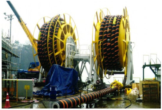
Figure 1.
Hose on the reel.
According to the requirements of the OCIMF code, the crush test should be performed for the offshore hose product. However, it is time consuming and expensive, which largely restricts the development efficiency of offshore hose products. To reduce the test cost, some theoretical and numerical method have been proposed to simulate the crush behavior of the offshore bonded rubber hose. Bai et al. numerically studied a new type of bonded hose which replaces the helix wire with a steel strip []. The behavior of the new type of hose is simulated with finite element models. Similarly, Choi numerically studied a new bonded hose which replaces steel wire with carbon-fiber-reinforced epoxy composite coil springs []. Qi et al. and Wei et al. also studied the crush behavior of the offshore bonded hose, and a revealed relationship between the crush load bearing capacity and parameters including the initial ovality, wire diameter, and helix pitch [,].
Although the study on the crush load response behavior of the offshore bonded rubber hose is limited, other studies, especially the theoretical studies on the response to other loads including the tensile load, inner pressure, and bending moment, are of great reference significance to the present study. Gonzalez et al. studied the response of the bonded hose to five axisymmetric loads with FEM and analytical methods []. They proposed a method equalizing the composite layer as the tensile armor layer, and demonstrated its accuracy in the prediction of rigidity, stress, and strain. Zhou et al. proposed a theoretical model of the fiver reinforced layer based on the anisotropic mechanical model for a layered composite material []. Gao et al. modeled the steel wire and fiber-reinforced layer with the Euler–Bernoulli beam theory and Donnell shell theory, respectively, and proposed a theoretical model to predict the response of the bonded hose to inner pressure []. In addition to theoretical studies, the finite element method is mature to study the behavior of a bonded composite hose, which could be a great reference for the study of the behavior of an offshore bonded composite hose under crush load. Amaechi et al. proposed a numerical method to predict the stress and strain distribution of the bonded composite hose under collapse and burst loads based on the finite element method []. Szabo et al. numerically studied the mechanical behavior of a filament–wound composite tube []. Alfredo et al. replaced the helix armor of unbonded composite pipe with equally spaced rings in the finite element model, and proved the effectiveness of the method in simulating the pipe’s response to collapse load [].
In a previous study, the response of the composite bonded hose under lateral crush load was mainly investigated with finite element analysis, which is indicative of a lack of theoretical understanding and is less efficient. In this study, a method to analyze the response of the composite rubber hose under the lateral crush load is proposed by equalizing the composite hose with a homogeneous pipe. First, the analysis method for the response of a homogeneous pipe under a lateral crush load is introduced. Then, the mechanical parameters of the equivalent homogeneous pipe are deduced. The global mechanical parameters of the hose are deduced based on the composite material mechanics, and the thickness of the equivalent homogeneous pipe is deduced based on the equivalence of strain energy. Assuming a certain boundary condition for the homogeneous pipe, the strain energy of the hose is a function of its thickness. The strain energy is calculated with a corresponding composite hose model and adopted to calculate the equivalent thickness. Finally, a composite rubber hose specimen is tested, and the test result is used to validate the proposed method. The test case is simulated with an FEM model and is also analyzed with the proposed method. A comparison shows that the proposed method is effective in predicting the composite response to lateral crush load. The proposed method is believed to also be effective in the analysis of the hose response to inner pressure and collapsing load. It is supposed to be an effective tool for the future design of an offshore composite rubber hose.
2. Hose Response to Crush Load
A typical bonded composite hose body consists of several laminates. For a floating hose, the body is usually covered by flotation foam which is protected by an outer cover to provide flotation capacity for the hose. The body consists of five laminates, which are the lining, the first cord/rubber reinforcement laminate, the wire/rubber reinforcement laminate, the second cord/rubber reinforcement laminate, and the cover from the inner side to the outer side. The inner lining is usually made of oil inert nitrile butadiene rubber to provide sealing capacity. The cord/rubber reinforcement laminate consists of several plies with cords embedded in elastomeric matrix. The cords are arranged at crossed +/− angles with respect to the longitudinal axis of the hose, producing an elastomeric composite structure with good flexibility and high strength. The wire/rubber reinforcement laminate is actually a stiffener of helix steel wire to withstand loads such as the inner pressure and crush load.
2.1. Pipe Response to Lateral Crush
For a ring laterally loaded by a concentrated load P, the problem is symmetric. As sketched in Figure 2, the problem is symmetric to the A–C line, and the A–B–C arc represents half of the ring. The concentrated load P is applied at the middle point B of the arc. The boundary condition and load on the A and C point are symmetric with respect to the O–B line. There is a supporting force and a bending moment acting at the point A and C.
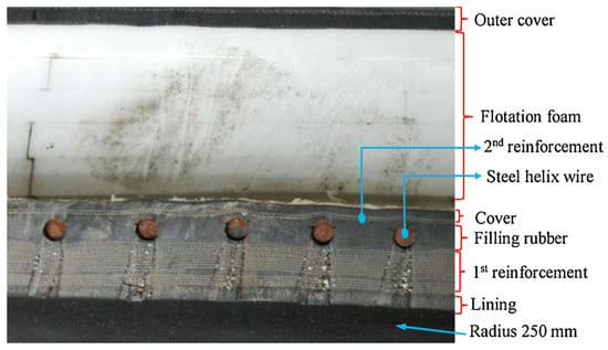
Figure 2.
Typical configuration of a bonded composite hose body [].
As shown in Figure 3, the ring arc is described in the polar coordinate system (, ). Denoting the radial displacement of the ring as , for any point on the arc A–B–C, the relationship between the radial displacement and the bending moment is as follows:
in which E is the Young’s Modulus, I is the section inertia moment, and R is the radius of the ring. The bending moment at any point in the ring is Equation (2).
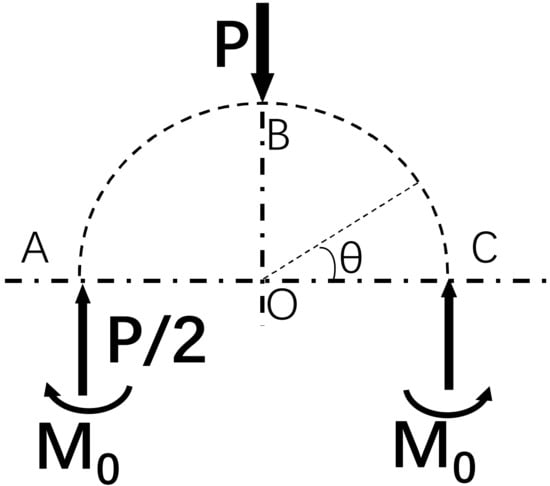
Figure 3.
Schematic diagram of the mechanical model of a crushed ring.
The bending moment can be found from Castigliano’s theorem []. The strain energy of the ring is expressed as follows.
According to the Castigliano’s theorem, the partial derivative of the strain energy with respect to the bending moment is equal to the angle of rotation of cross-section A of the ring (see Figure 3). Therefore, the bending moment at point A and C is expressed as follows.
Then, the radial displacement can be obtained by solving the differential function Equation (1), which is as follows.
As shown in Figure 4, for a pipe section laterally loaded with a line load P, it could be simplified as a plane stress problem, and the radial displacement on the pipe could be obtained by replacing the bending rigidity EI. The elastic modulus E should be replaced by E/(1 − 2), and the I should be replaced by h3/12, in which h is the thickness of the pipe shell. The displacement between point B and D is the deflection under the load P. Therefore, the crush rigidity can be expressed as Equation (6).
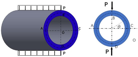
Figure 4.
Schematic diagram of a hose subjected to lateral crush load.
2.2. Global Mechanical Parameters of the Hose
As introduced earlier, the bonded hose is a composite structure of several laminates. By adopting Equation (6) to calculate the response under crush load, the global mechanical parameters of the composite structure can be determined. Either the cord/rubber reinforcement ply or the wire/rubber reinforcement can be treated as a two-components composite structure. The reinforcement structure, e.g., the cord or the wire, is in the shape of a helix. The axis of the helix is at an angle with respect to the longitudinal axis of the hose. Therefore, a global coordinate system and a local coordinate system are defined on the hose shell, as shown in Figure 5. In the global Cartesian coordinate system x–y–z, the x axis is in the axial direction of the hose, the y axis is in the circumferential direction, and the z axis is in the radial direction. The local coordinate system 1–2–3 is established by rotating the global coordinate system about the z axis by the helix angle .
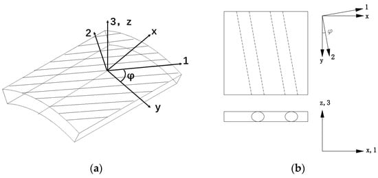
Figure 5.
Diagram of the hose element: (a) coordinate system; (b) sectional sketch.
The global mechanical parameters of the composites can be deduced with the mixture theory. For the above shell element, the area of the cross-section in the x–z plane is the sum of the base material and the embedded material, which is expressed as Equation (7).
in which is the cross-section area, is the cross-section area of the embedded material, and is the cross-section area of the base material. The subscripts m and f denote the base material and embedded material, respectively, and the subscript y denotes the y direction in the coordinate system in Figure 4. Similarly, in following equations, the subscript z denotes the z direction in the coordinate system in Figure 4.
For the x–z cross section, the force acting on the x–z cross-section is borne by both the base material and the embedded material. It could be expressed as Equation (8).
in which and are the forces acting on the base material and the embedded material, respectively.
Obviously, in the y direction, the strain of the base material and the embedded material is equal to the global strain of the composites, .
in which and are the strain of the base material and the embedded material, respectively.
The force contributed by the base material and the embedded material can be calculated by the following equations.
in which and are the elastic modulus of the base material and the embedded material, respectively.
Therefore, substituting Equations (9)–(11) into Equation (8), the global elastic modulus of the composites in the y direction can be deduced as
in which is the cross-section area ratio of the embedded material in the x–z plane.
Similar to Equation (8), . For the x–y cross section, e.g., in the z direction, the deduction process is similar. The global elastic modulus of the composites in the z direction is expressed as Equation (13). Using the mixture theory, the Poisson’s ratio of the y–z cross section is calculated by Equation (14).
and the shear modulus in the x–z plane is deduced similarly and expressed as Equation (15):
As shown in Figure 3, the composite hose consists of several laminates. The global mechanical parameters of the hose shell can be calculated with the in-line model in composite material mechanics. Similarly, the area ratio of each layer is defined as follows:
where represents the volume ratio of the ith laminate from inside out; subscripts 1 and 2 represent the outer and inner radius of the layer; and and represent the outermost radius and innermost radius of the hose.
The global mechanical parameters , , , and of the hose shell are expressed as follows.
3. Determination of Equivalent Thickness
3.1. Strain Energy Equivalence
Traditionally, determination of the thickness is through the equivalence of the cross-section area. However, the traditional method for equivalent thickness is far from accurate []. A new method to determine the thickness of the equivalent homogeneous hose is proposed based on the equivalence of strain energy. In this method, an ideally constrained and loaded hose shell segment is assumed, which is a quarter of the hose, as shown in Figure 5.
In this assumed condition, the shell segment is circumferentially loaded at one end, and only the circumferential strain is allowed. The strain of the segment is expressed as
in which , , and are the strain in the circumferential, radial, and axial directions, respectively, while , , and are the corresponding shear strains.
For a pipe section under the plain stress state, the circumferential strain is expressed as,
and the relationship between the stress and the strain should be expressed as
in which is the Poisson’s ratio in the cylindrical coordinate system. The strain energy density for a continuous shell should be as Equation (23).
As for the assumed pipe segment in Figure 5, the radial displacement is constrained, and the radial strain is ignored; then, Equations (21)–(23) can be simplified as Equations (24)–(26).
in which .
As the circumferential strain is uniform inside the model, the strain energy can be obtained through integration of the strain energy density:
in which is the radius of the neutral surface of the hose shell, L is the length of the pipe segment, and t is the shell thickness.
If a corresponding bonded hose model is set up in the ABAQUS to obtain the strain energy , and equalize the with , the equivalent thickness of the bonded hose can be obtained.
3.2. Calculation of Strain Energy Based on FEM
An FEM model similar to the assumed model in Figure 6 was set up in ABAQUS, as shown in Figure 7. Only a quarter of the hose was modeled, and the length is 2 times the pitch. The hose comprises the wire and the composite part. The wire is modeled with solid elements, and the laminate layers are modeled with the composite layup method provided in ABAQUS []. With the composite layup method, the properties of the reinforcement and the base material properties are input, and the mechanical properties of the composites are calculated automatically.
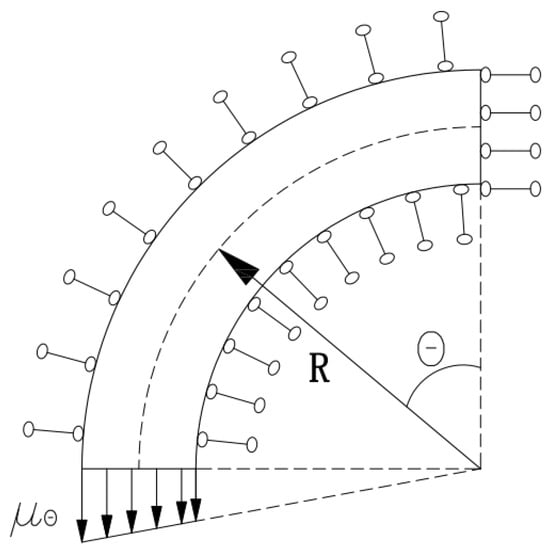
Figure 6.
Diagram of the ideally assumed hose segment.
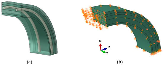
Figure 7.
Simplified FEM model for the strain energy calculation: (a) general configuration; (b) boundary condition.
4. Model Validation
A 12-inch hose was selected to validate the proposed model. It has an inner diameter of 152.4 mm and an outer diameter of 194 mm. Each ply is 0.7 mm thick, and it crosses at +/− 45° with respect to the longitudinal axis of the hose. The inner composite layer has 10 pairs of +/− 45° plies, and the outer composite layer has 4 pairs of +/− 45° cord plies. The steel wire is 4 mm in radius, and the helix has a diameter of 176.4 mm and a helix angle of 80°. The structural parameters of the hose are listed in Table 1.

Table 1.
Structural parameters of the hose.
The mechanical parameters of the structural components are listed in Table 2.

Table 2.
Mechanical parameters of the structural components of the hose.
4.1. Experimental Study
The crush test was conducted according to the requirement of the OCIMF regulation. The set-up of the test system is shown in Figure 8. The system mainly consists of the loading frame (component 1), the specimen (component 6), the loading apparatus, and the sensing system. The test specimen was place on a fixed rigid plate (component 2) and crushed by a moving rigid plate (component 3) actuated by an electrical cylinder which is mounted on the loading frame. The displacement and the pressure were measured with sensors (component 4 and 5) and recorded by a computer (component 7).
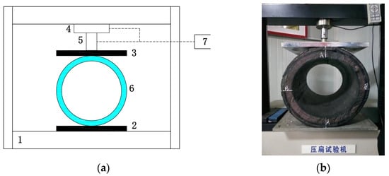
Figure 8.
Set-up of the test system: (a) sketch of the test system; (b) picture of the test.
In this test, a 500 mm long hose segment was tested. According to the requirement of the OCIMF code, the load was increased to 12 kN. At the moment, the corresponding radial displacement of the hose due to the crush load is 28 mm. Then, the elastic crush rigidity of the hose is 0.857 N/mm2.
4.2. FEM Simulation
A corresponding FEM model was established to numerically simulate the structural response to the crush load, as shown in Figure 9. The modeling of the hose is similar to Section 3.2 and that of []. The hose is crushed by a rigid block in the FEM model. The length of the hose is also 500 mm. The contact between the hose and the rigid block is modeled as surface-to-surface contact with a friction coefficient of 0.3. To constrain the rigid displacement, one end of the hose is constrained as follows. At the hose end, the axial displacement is constrained, and the centerlines at the x–y surface and the y–z surface are symmetrically constrained.
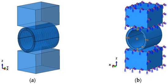
Figure 9.
FE model for the crush simulation: (a) general configuration; (b) boundary condition.
In this model, the total number of elements is 16,908. Among them, the mesh number of the composite part is 12,716, and the mesh number of the wire is 3440. The element type of both the wire and the composite part is C3D8R. The element type of the two rigid blocks is R3D4 and the number is 752. To compensate the computation cost and precision, the present mesh density is supposed to be proper, as it has been proved in ref. [].
A displacement of 10 mm is loaded to the hose, under which the displacement of the hose and the stress distribution on the steel wire are plotted in Figure 10. It shows the maximum stress of the wire is 752.5 MPa, which is lower than its yield stress, which implies the deformation is in the elastic range. This is also demonstrated by the linear load-displacement relationship which is plotted in Figure 11. It is shown that the displacement increases linearly with the load, which agrees with Qi et al. []. The rate of the curve in Figure 11 is the crush rigidity of the hose. In this case, the crush rigidity of the hose is 1.2 N/mm2.
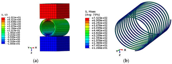
Figure 10.
FE result of the hose under crush load: (a) displacement; (b) stress.
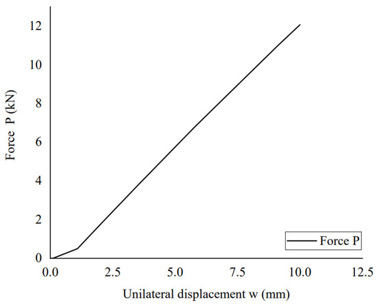
Figure 11.
Calculated load-displacement relationship with the FE model.
4.3. Validation
The proposed method was also used to calculate the response of the test specimen to the crush load. First, the global mechanical properties of the model were calculated according to the equations in Section 2.2. The parameters of each laminate and the global properties of the hose are listed in Table 3.

Table 3.
Calculated mechanical properties of the laminates and the hose.
Then, a simplified finite element model was set up with the method in Section 3.2 to calculate the equivalent shell thickness. The model was loaded with a circumferential strain of 0.003, under which the displacement and strain distribution are plotted in Figure 12. The strain energy was extracted from the FE model, and the equivalent thickness was calculated with Equation (28). The calculated strain energy of the model is 11,533.8 mJ, and the calculated equivalent thickness is 7.44 mm.

Figure 12.
Result of the simplified FE model: (a) circumferential displacement; (b) circumferential strain.
Finally, the crush rigidity of the hose was calculated with Equation (5). It was compared with the FEM and test results, as listed in Table 4. It is shown that the proposed method agrees well with the test with an overestimation of 18.2%, while the FEM result overestimates the rigidity by 40.8%. The difference between the proposed method and the test could be attributed to several issues. One is the initial imperfection of the test specimen, which reduces the rigidity of the hose, but is not considered in the present model. Another is that the mechanical properties of the materials may vary in the vulcanization process. Furthermore, the hose is idealized as a shell in the proposed method, although its thickness to diameter ratio is about 1:9.3. However, an error less than 20% is supposed to be acceptable, while it greatly simplifies the process to predict the crush behavior of the hose. In addition, the radial displacement under the standard load of 12 kN is 10.2 mm, as shown in Figure 10. Therefore, for the equivalent shell, the normal deflection to shell thickness ratio is about 1.37. As the normal deflection and the shell thickness are in the same order of magnitude, the equivalent shell model is supposed to be applicable.

Table 4.
Comparison of the proposed method with FEM and physical test.
5. Conclusions
A simplified theoretical method is proposed to predict the response of an offshore bonded composite hose to lateral crush load. It equalizes the composite hose with a homogeneous hose. The mechanical parameters of the equivalent hose are deduced based on the rule of mixture of composite, and the thickness of the equivalent hose is determined based on the strain energy equivalence. The strain energy of the equivalent hose is calculated with FEM analysis of the corresponding composite hose, and then the thickness is calculated.
The proposed method is validated against an indoor test. The predicted hose response to the crush load with the proposed method agrees well with the test. It tends to overestimate the crush rigidity by 18.2%. This is probably because the initial imperfection of the test specimen reduces the rigidity of the hose. Due to the limited computational power, the mesh density may also have a certain influence on the calculation results. However, to reduce the influence of mesh density, the mesh density in the FEM analysis of both the structural response and the strain energy calculation is similar, and the mesh density is determined on the expertise. The proposed method can also be used to predict the hose response to other kinds of loads, such as the inner pressure and collapsing load.
The proposed method equalizes the composite hose to a homogeneous hose. It can be applied not only to the crush problem in present study, but also to other problems such as the collapse and burst problem. Those will be studied in future work. In general, the proposed method could be a valuable tool for the future design and analysis of the offshore bonded composite hose.
Author Contributions
Conceptualization, P.G. and C.L.; methodology, P.G. and C.L.; software, C.L.; validation, P.G. and C.L.; formal analysis, P.G.; investigation, C.L.; resources, P.G. and Q.G.; data curation, C.L.; writing—original draft preparation, P.G.; writing—review and editing, P.G.; visualization, C.L.; supervision, H.W.; project administration, Y.L.; funding acquisition, P.G. All authors have read and agreed to the published version of the manuscript.
Funding
This research was funded by the State Key Laboratory of Marine Resource Utilization in South China Sea, grant number MRUKF2021024.
Data Availability Statement
Not applicable.
Acknowledgments
The authors greatly thank the Hebei Zebung Rubber Technology Co., Ltd., for providing the test data, and many thanks are given to those who facilitated the successful operation of the tests.
Conflicts of Interest
The authors declare no conflict of interest.
References
- Amaechi, C.V.; Wang, F.; Ja’e, I.A.; Aboshio, A.; Odijie, A.C.; Ye, J. A literature review on the technologies of bonded hoses for marine applications. Ships Offshore Struct. 2022, 17, 2819–2850. [Google Scholar] [CrossRef]
- Amaechi, C.V.; Chesterton, C.; Butler, H.O.; Wang, F.; Ye, J. Review on the design and mechanics of bonded marine hoses for Catenary Anchor Leg Mooring (CALM) buoys. Ocean Eng. 2021, 242, 110062. [Google Scholar] [CrossRef]
- Amaechi, C.V.; Chesterton, C.; Butler, H.O.; Gillet, N.; Wang, C.; Ja’e, I.A.; Reda, A.; Odijie, A.C. Review of Composite Marine Risers for Deep-Water Applications: Design, Development and Mechanics. J. Compos. Sci. 2022, 6, 96. [Google Scholar] [CrossRef]
- OCIMF. Guide to Purchasing and Manufacturing Hoses for Offshore Moorings; OCIMF: London, UK, 2009. [Google Scholar]
- Gao, Q.; Zhang, P.; Duan, M.; Yang, X.; Shi, W.; An, C.; Li, Z. Investigation on structural behavior of ring-stiffened composite offshore rubber hose under internal pressure. Appl. Ocean Res. 2018, 79, 7–19. [Google Scholar] [CrossRef]
- Tonatto, M.L.P.; Forte, M.M.C.; Tita, V.; Amico, S.C. Progressive damage modeling of spiral and ring composite structures for offloading hoses. Mater. Des. 2016, 108, 374–382. [Google Scholar] [CrossRef]
- Choi, B.L.; Choi, B.H. Numerical method for optimizing design variables of carbon-fiber-reinforced epoxy composite coil springs. Compos. Part B Eng. 2015, 82, 42–49. [Google Scholar] [CrossRef]
- Wei, D.; An, C.; Zhang, J.; Huang, Y.; Gu, C. Effect of Winding Steel Wire on the Collapse Pressure of Submarine Hose. J. Mar. Sci. Eng. 2022, 10, 1365. [Google Scholar] [CrossRef]
- Qi, S. Study on Radical Pressure Stability of Bonded Flexible Tube; China University of Petroleum: Beijing, China, 2018. [Google Scholar]
- Gonzalez, G.M.; de Sousa, J.R.M.; Sagrilo, L.V.S. A study on the axial behavior of bonded flexible marine hoses. Mar. Syst. Ocean Technol. 2016, 11, 31–43. [Google Scholar] [CrossRef]
- Zhou, Y.; Duan, M.; Ma, J.; Sun, G. Theoretical analysis of reinforcement layers in bonded flexible marine hose under internal pressure. Eng. Struct. 2018, 168, 384–398. [Google Scholar] [CrossRef]
- Gao, P.; Gao, Q.; An, C.; Zeng, J. Analytical modeling for offshore composite rubber hose with spiral stiffeners under internal pressure. J. Reinf. Plast. Compos. 2020, 40, 352–364. [Google Scholar] [CrossRef]
- Amaechi, C.V.; Chesterton, C.; Butler, H.O.; Gu, Z.; Odijie, A.C.; Wang, F.; Hou, X.; Ye, J. Finite Element Modelling on the Mechanical Behaviour of Marine Bonded Composite Hose (MBCH) under Burst and Collapse. J. Mar. Sci. Eng. 2022, 10, 151. [Google Scholar] [CrossRef]
- Szabó, G.; Váradi, K.; Felhős, D. Bending Analysis of a Filament-Wound Composite Tube. Mod. Mech. Eng. 2018, 8, 66–77. [Google Scholar] [CrossRef]
- Gay Neto, A.; de Arruda Martins, C. A comparative wet collapse buckling study for the carcass layer of flexible pipes. J. Offshore Mech. Arct. Eng. 2012, 134, 031701. [Google Scholar] [CrossRef]
- Timoshenko, S.P.; Gere, J.M. Theory of Elastic Stability; Courier Corporation: North Chelmsford, MA, USA, 2009. [Google Scholar]
- Tang, M.; Lu, Q.; Yan, J.; Yue, Q. Buckling collapse study for the carcass layer of flexible pipes using a strain energy equivalence method. Ocean Eng. 2016, 111, 209–217. [Google Scholar] [CrossRef]
- Dassault Systèmes. Abaqus Analysis User’s Guide; Dassault Systèmes: Providence, RI, USA, 2015. [Google Scholar]
Disclaimer/Publisher’s Note: The statements, opinions and data contained in all publications are solely those of the individual author(s) and contributor(s) and not of MDPI and/or the editor(s). MDPI and/or the editor(s) disclaim responsibility for any injury to people or property resulting from any ideas, methods, instructions or products referred to in the content. |
© 2023 by the authors. Licensee MDPI, Basel, Switzerland. This article is an open access article distributed under the terms and conditions of the Creative Commons Attribution (CC BY) license (https://creativecommons.org/licenses/by/4.0/).