
Rapid Robust Control of a Marine-Vehicle Manipulator with Series Elastic Actuators Based on Variable Power Log Reaching Law

Abstract
:1. Introduction
- The majority of the existing studies have concentrated on traditional rigid-actuated marine-vehicle manipulators. As far as we know, few studies have considered marine-vehicle manipulators with compliant actuators;
- The strong dynamic coupling between the manipulator motion affected by base oscillations and the flexible vibration caused by compliant actuators poses a great challenge to the system control;
- The current reaching-law-based SMC method cannot achieve further improvement in convergence speed due to the problem of sliding mode chattering.
2. Problem Statements
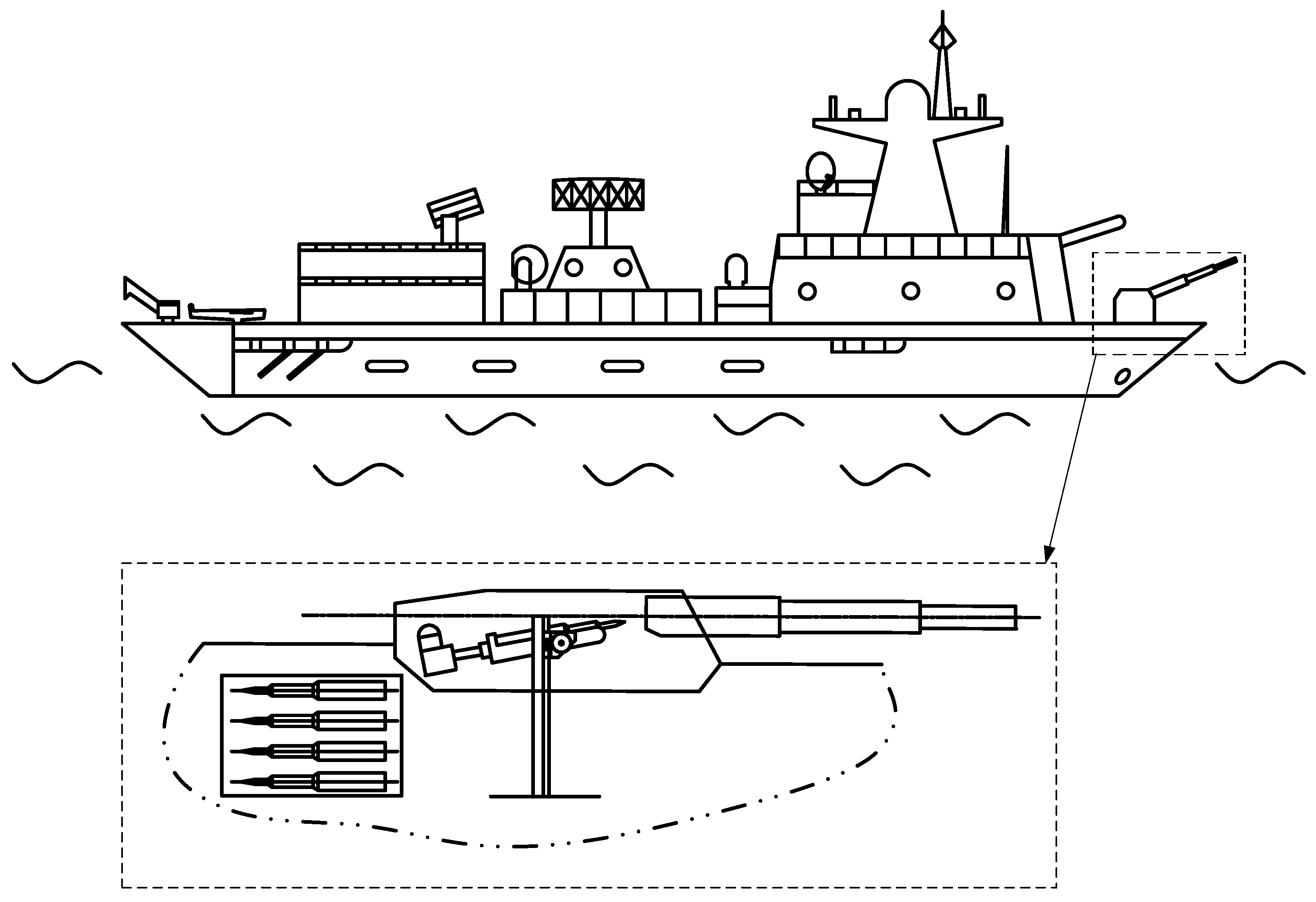
2.1. System Description
2.2. Rigid-Flexible Coupling Dynamic Model
- The manipulator can be reduced to a two-degree-of-freedom system if the flexible vibration from the compliant actuators is not considered;
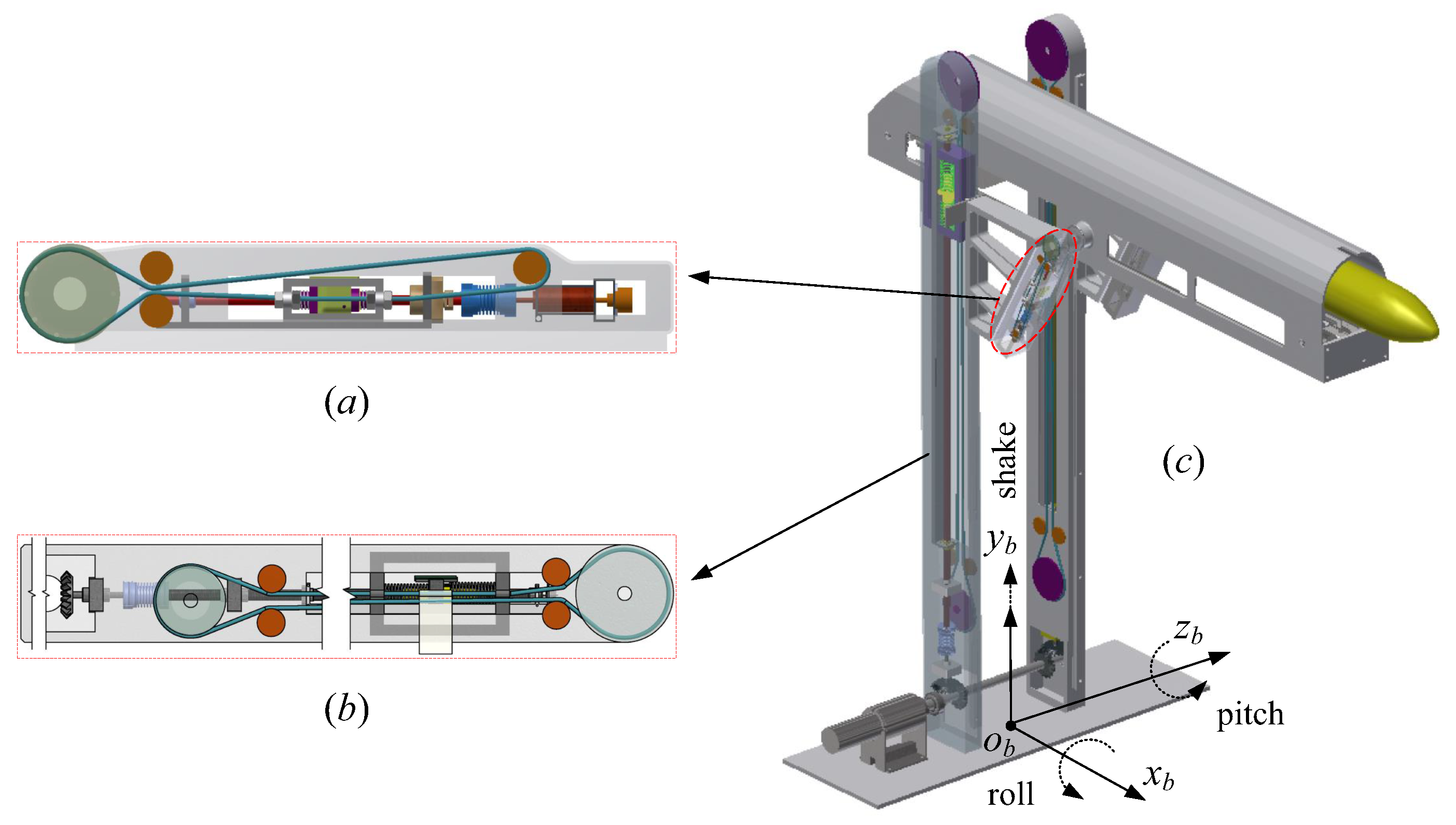
- If the two SEAs are reduced to two springs, two additional degrees of freedom are introduced, and the whole system becomes a four-degree-of-freedom system. In particular, the SEAs for the two parts are simplified as a linear tension spring and a linear torsion spring, respectively;
- Furthermore, considering the effect of oscillatory base and decoupling the base oscillation to three directions as shown in Figure 2, another degree of freedom is introduced. The final simplified system is a five-degree-of-freedom system.
3. Dynamics Decoupling Based on a Singular Perturbation Method
3.1. Slow Time-Scale Subsystem
3.2. Fast Time-Scale Subsystem
4. Main Development
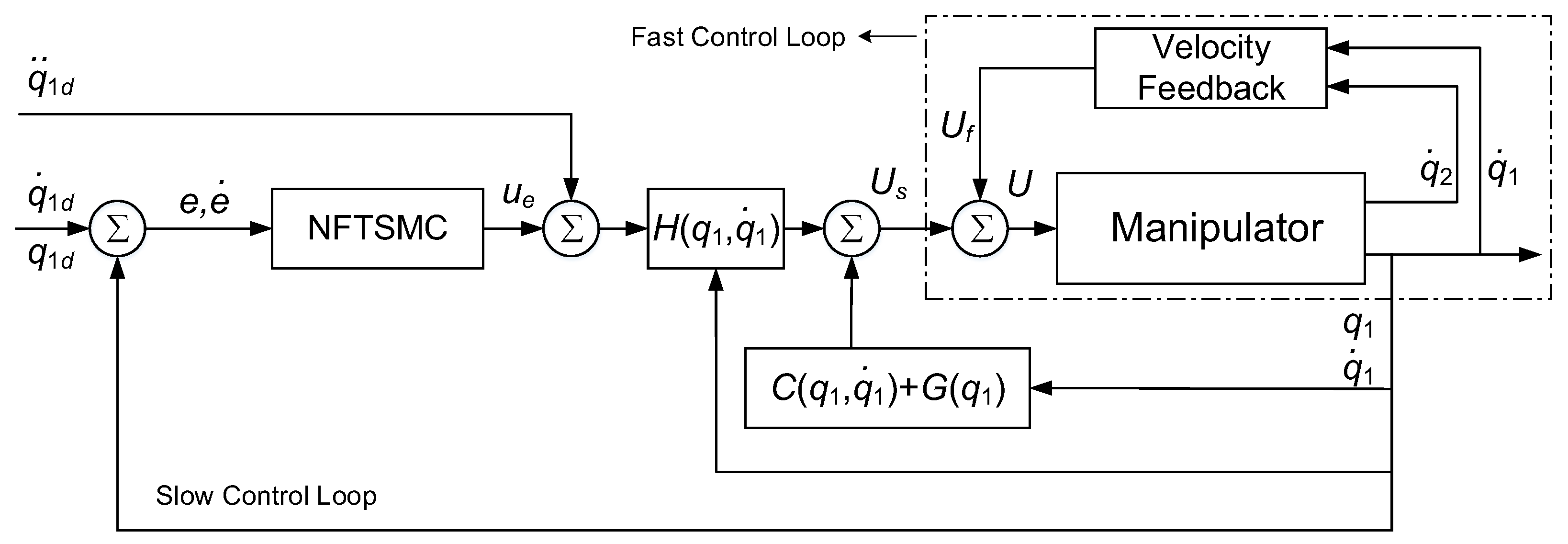
4.1. Slow Time-Scale Subsystem Control
4.1.1. Computed Torque Method
4.1.2. SMC with Variable Power Log Reaching Law
4.2. Fast-Time Scale Subsystem Control
5. Simulation Experiments
5.1. Experiment Setting
5.2. Results and Analysis
6. Conclusions
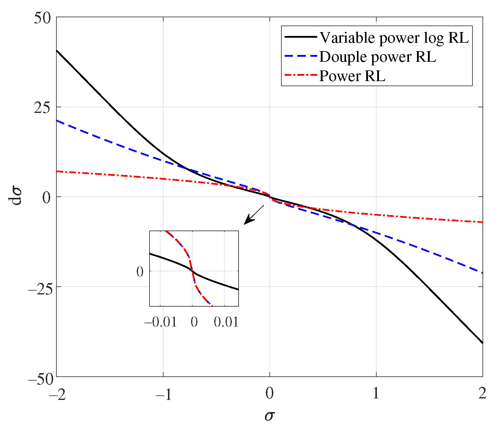
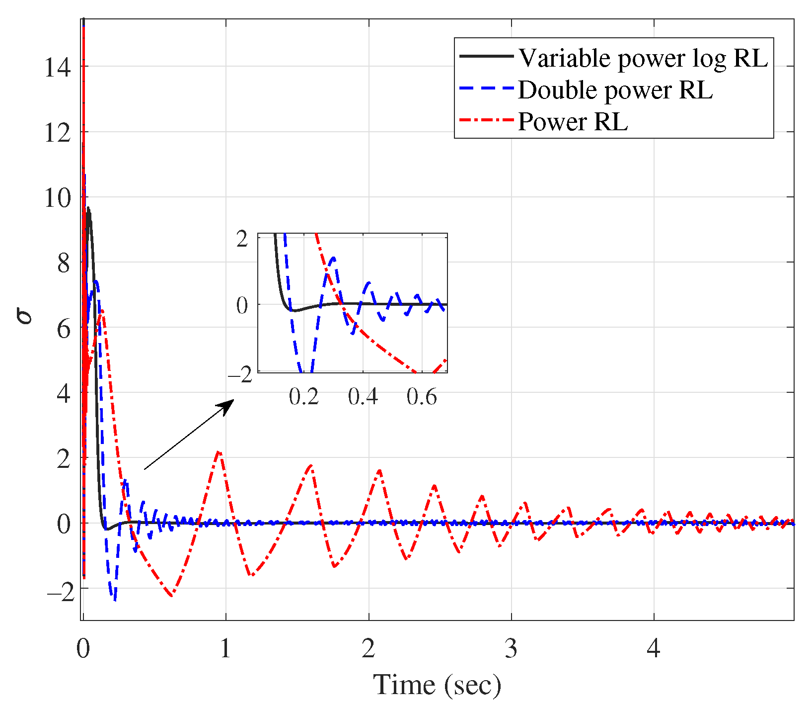
- The theoretical innovation of this study is that a novel SMC reaching law, i.e., the variable power log reaching law was proposed for the first time. It can provide a faster convergence speed away from the sliding mode surface, and maintain a better sliding mode chattering suppression performance close to the sliding mode surface. This is the primary contribution and innovation of this study;
- The innovative aspect of the application of this study is that we investigated for the first time the problem of rapid robust control of a marine-vehicle manipulator considering both base oscillations and SEA-induced flexible vibrations, and proposed a novel solution to this problem based on the singular perturbation method and the SMC method with the above novel reaching law.
Author Contributions
Funding
Institutional Review Board Statement
Informed Consent Statement
Data Availability Statement
Conflicts of Interest
References
- Zhang, D.; Zhao, B.; Zhu, K.; Jiang, H. Dynamic analysis of full-circle swinging hoisting operation of a large revolving offshore crane vessel under different wave directions. J. Mar. Sci. Eng. 2023, 11, 197. [Google Scholar] [CrossRef]
- Fang, Y.; Wang, P.; Sun, N.; Zhang, Y. Dyanamics analysis and nonlinear control of an offshore boom crane. IEEE Trans. Ind. Electron. 2014, 61, 414–427. [Google Scholar] [CrossRef]
- Hu, D.; Qian, Y.; Fang, Y.; Chen, Y. Modeling and nonlinear energy-based anti-swing control of underactuated dual ship-mounted crane systems. Nonlinear Dyn. 2021, 106, 323–338. [Google Scholar] [CrossRef]
- Xue, G.; Liu, Y.; Shi, Z.; Guo, L.; Li, Z. Research on trajectory tracking control of underwater vehicle manipulator system based on model-free adaptive control method. J. Mar. Sci. Eng. 2022, 10, 652. [Google Scholar] [CrossRef]
- Simetti, E.; Casalino, G. Manipulation and transportation with cooperative underwater vehicle manipulator systems. IEEE J. Ocean. Eng. 2017, 42, 782–799. [Google Scholar] [CrossRef]
- Xiong, X.; Xiang, X.; Wang, Z.; Yang, S. On dynamic coupling effects of underwater vehicle-dual-manipulator system. Ocean Eng. 2022, 258, 111699. [Google Scholar] [CrossRef]
- Chang, Z.; Zhang, Y.; Zheng, Z.; Zhao, L.; Shen, K. Dynamics simulation of grasping process of underwater vehicle manipulator system. J. Mar. Sci. Eng. 2021, 9, 1131. [Google Scholar] [CrossRef]
- Leban, F.A.; Diaz-Gonzalez, J.; Parker, G.G.; Zhao, W. Inverse kinematic control of a dual crane system experiencing base motion. IEEE Trans. Control Syst. Technol. 2015, 23, 331–339. [Google Scholar] [CrossRef]
- Sato, M.; Toda, M. Robust motion control of an oscillatory-base manipulator in a global coordinate system. IEEE Trans. Ind. Electron. 2015, 62, 1163–1174. [Google Scholar] [CrossRef]
- Londhea, P.S.; Mohanb, S.; Patrea, B.M.; Waghmarea, L.M. Robust task-space control of an autonomous underwater vehicle-manipulator system by PID-like fuzzy control scheme with disturbance estimator. Ocean Eng. 2017, 139, 1–13. [Google Scholar] [CrossRef]
- Cai, Y.; Zheng, S.; Liu, W.; Qu, Z.; Zhu, J.; Han, J. Sliding-mode control of ship-mounted Stewart platforms for wave compensation using velocity feedforward. Ocean Eng. 2021, 236, 109477. [Google Scholar] [CrossRef]
- Sun, N.; Yang, T.; Chen, H.; Fang, Y. Dynamic feedback antiswing control of shipboard cranes without velocity measurement: Theory and hardware experiments. IEEE Trans. Industr. Inform. 2019, 15, 2879–2891. [Google Scholar] [CrossRef]
- Zhang, R.; Chen, H. An adaptive tracking control method for offshore cranes with unknown gravity parameters. Ocean Eng. 2022, 260, 111809. [Google Scholar] [CrossRef]
- Zhou, Z.; Tang, G.; Xu, R.; Han, L.; Cheng, M. A novel continuous nonsingular finite-time control for underwater robot manipulators. J. Mar. Sci. Eng. 2021, 9, 269. [Google Scholar] [CrossRef]
- Wang, Y.; Chen, B.; Wu, H. Joint space tracking control of underwater vehicle-manipulator systems using continuous nonsingular fast terminal sliding mode. Proc. Inst. Mech. Eng. Part M 2018, 232, 448–458. [Google Scholar] [CrossRef]
- Han, L.; Tang, G.; Cheng, M.; Huang, H.; Xi, D. Adaptive nonsingular fast terminal sliding mode tracking control for an underwater vehicle-manipulator system with extended state observer. J. Mar. Sci. Eng. 2021, 9, 501. [Google Scholar] [CrossRef]
- Dai, Y.; Gao, H.; Yu, S.; Ju, Z. A fast tube model predictive control scheme based on sliding mode control for underwater vehicle-manipulator system. Ocean Eng. 2022, 254, 111259. [Google Scholar] [CrossRef]
- Rohith, G. Fractional power rate reaching law for augmented sliding mode performance. J. Franklin Inst. 2020, 358, 856–876. [Google Scholar] [CrossRef]
- Wang, Y.Q.; Feng, Y.T.; Zhang, X.G. A new reaching law for anti disturbance sliding-mode control of PMSM speed regulation system. IEEE Trans. Power Electron. 2020, 35, 4117–4126. [Google Scholar] [CrossRef]
- Mozayan, S.M.; Saad, M.; Vahedi, H. Sliding mode control of PMSG wind turbine based on enhanced exponential reaching law. IEEE Trans. Ind. Electron. 2016, 63, 6148–6159. [Google Scholar] [CrossRef]
- Yu, S.; Yu, X.; Shirinzadeh, B. Continuous finite-time control for robotic manipulators with terminal sliding mode. Automatica 2005, 41, 1957–1964. [Google Scholar] [CrossRef]
- Pan, J.; Li, W.; Zhang, H. Control algorithms of magnetic suspension systems based on the improved double exponential reaching law of sliding mode control. Int. J. Control Autom. Syst. 2018, 16, 2878–2887. [Google Scholar] [CrossRef]
- Guo, Y.; Hou, B. Implicit Lyapunov function-based tracking control of a novel ammunition autoloader with base oscillation and payload uncertainty. Nonlinear Dyn. 2017, 87, 741–753. [Google Scholar]
- Guo, Y.; Hou, B.; Xu, S.; Mei, R.; Wang, Z.; Van, T.H. Robust stabilizing control for oscillatory base manipulators by implicit Lyapunov method. Nonlinear Dyn. 2023, 108, 2245–2262. [Google Scholar] [CrossRef]
- Guo, Y.; Xi, B.; Mei, R.; Xu, S.; Wang, Z. Singular-perturbed control for a novel SEA-actuated MBT autoloader subject to chassis oscillations. Nonlinear Dyn. 2020, 101, 2263–2281. [Google Scholar] [CrossRef]
- Lin, Z.; Wang, H.D.; Karkoub, M.; Shah, U.H.; Li, M. Prescribed performance based sliding mode path-following control of UVMS with flexible joints using extended state observer based sliding mode disturbance observer. Ocean Eng. 2021, 240, 109915. [Google Scholar] [CrossRef]
- Dehkordi, S.F. Dynamic analysis of flexible-link manipulator in underwater applications using Gibbs-Appell formulations. Ocean Eng. 2021, 241, 110057. [Google Scholar] [CrossRef]
- Wang, T.; Zheng, T.; Zhao, S.; Sui, D.; Zhao, J.; Zhu, Y. Design and control of a series-parallel elastic actuator for a weight-bearing exoskeleton robot. Sensors 2022, 22, 1055. [Google Scholar] [CrossRef]
- Al-Dahiree, O.S.; Ghazilla, R.A.R.; Tokhi, M.O.; Yap, H.J.; Albaadani, E.A. Design of a compact energy storage with rotary series elastic actuator for lumbar support exoskeleton. Machines 2022, 10, 584. [Google Scholar] [CrossRef]
- Zhu, J.; Zhang, J.; Zhu, J.; Zeng, L.; Pi, Y. A composite controller for manipulator with flexible joint and link under uncertainties and disturbances. J. Vib. Control 2022, 28, 1148–1164. [Google Scholar] [CrossRef]
- Cheng, X.; Zhang, Y.; Liu, H.; Wollherr, D.; Buss, M. Adaptive neural backstepping control for flexible-joint robot manipulator with bounded torque inputs. Neurocomputing 2021, 458, 70–86. [Google Scholar] [CrossRef]
- Hong, M.; Gu, X.; Liu, L.; Guo, Y. Finite time extended state observer based nonsingular fast terminal sliding mode control of flexible-joint manipulators with unknown disturbance. J. Franklin Inst. 2023, 360, 18–37. [Google Scholar] [CrossRef]
- Yu, H.; Huang, S.; Chen, G.; Thakor, N. Control design of a novel compliant actuator for rehabilitation robots. Mechatronics 2013, 23, 1072–1083. [Google Scholar] [CrossRef]
- Zuo, Z.; Tie, L. Distributed robust finite-time nonlinear consensus protocols for multi-agent systems. Int. J. Syst. Sci. 2014, 47, 1–10. [Google Scholar] [CrossRef]
- Zuo, Z. Nonsingular fixed-time consensus tracking for second-order multi-agent networks. Automatica 2015, 54, 305–309. [Google Scholar] [CrossRef]
- Yu, T.; Liu, Y.; Cao, J.; Alsaadi, F.E. Finite-time stability of dynamical system under event-triggered hybrid control. Appl. Math. Model. 2023, 117, 286–295. [Google Scholar] [CrossRef]
- Ortega, R.; Van Der Schaft, A.J.; Mareels, I.; Maschke, B. Robust control of flexible-joint robots using voltage control strategy. IEEE Control Syst. Mag. 2001, 21, 18–33. [Google Scholar]


| Symbols | Meanings |
|---|---|
| XOY | Inertial coordinate |
| xoy | Noninertial (base-fixed) coordinate |
| , , | Oscillatory base, Lifting part, Rotating part |
| , | Actuators of two parts |
| , | Springs of two parts |
| , | Centroid of two parts |
| , | Geometric parameters |
| , , | Three base oscillations |
| , | Position/angle of two parts |
| , | Position/angle of two actuators |
| Group No. | Reaching Law | Base Oscillation | Payload Uncertainty | Fast Control |
|---|---|---|---|---|
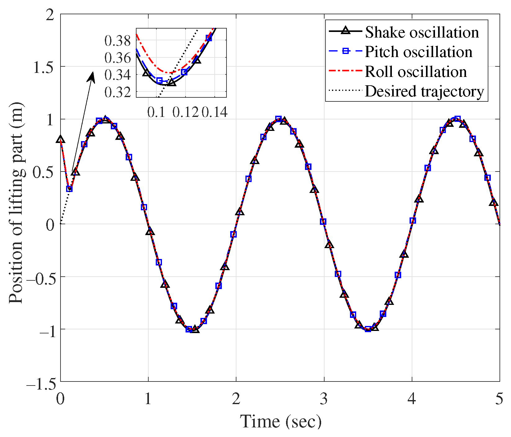
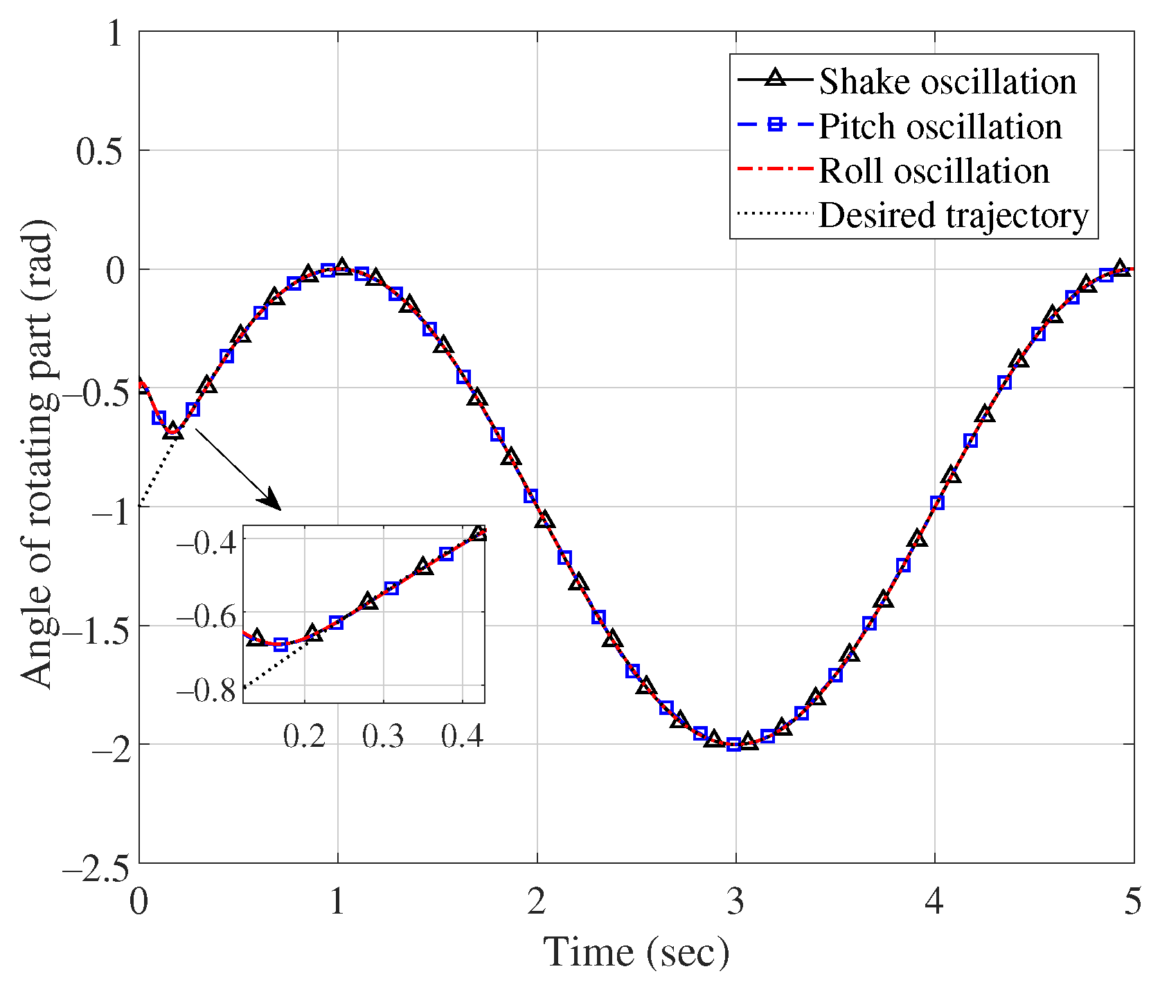
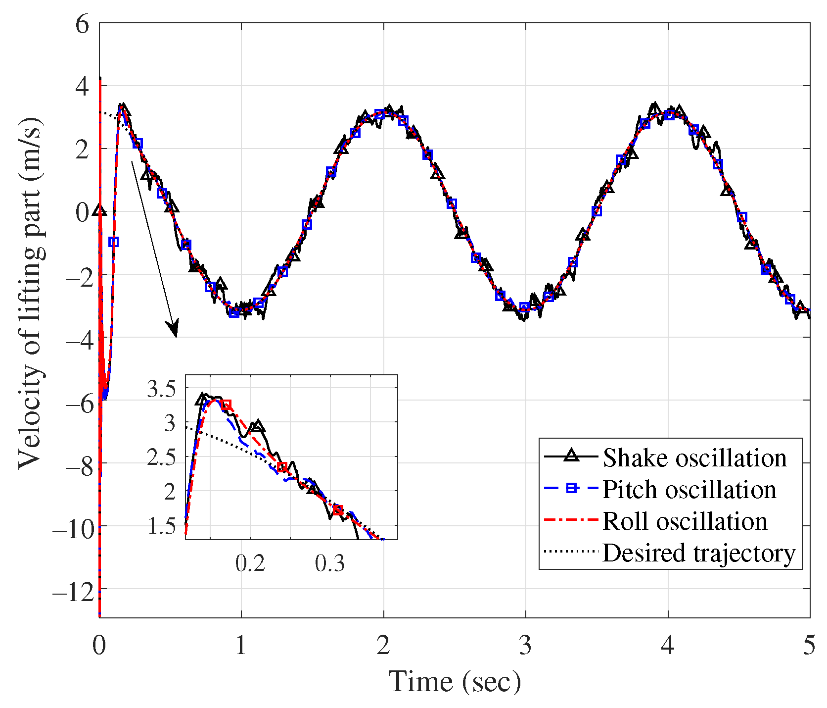
| Group 1 | Variable power log | Three oscillations | N | On |
| Group 2 | Three reaching laws | Shake oscillation | N | On |
| Group 3 | Variable power log | Shake oscillation | Y | On |
| Group 4 | Variable power log | Shake oscillation | N | Off |
| Parameters | Values | Parameters | Values | Parameters | Values |
|---|---|---|---|---|---|
| /kg | 10 | /kg | 40 | g/(N/kg) | 9.8 |
| /kg | 2 | I/kgm | 0.01 | L/m | 0.74 |
| /(Nm/rad) | 2 | /(Nm/rad) | 2 | ||
| 3 | 5 | 12 | |||
| r | 3 | p | 1 | l | 3 |
| m | 1 | 0.5 | 5 | ||
| 12/5 (i = 1/2) | 5 | 10 | |||
| 2 | 0.9 |
| Group No. | Case | Response Time/s | Settling Time/s | Max Overshoot/m or rad | Steady-State Error/m or rad |
|---|---|---|---|---|---|
| Group 1 | Shake | 0.01/0.16 | 0.20/0.21 | 0.04/0 | 0.015/0.001 |
| Pitch | 0.01/0.16 | 0.20/0.21 | 0.04/0 | 0.003/0.003 | |
| Roll | 0.01/0.16 | 0.20/0.21 | 0.03/0 | 0/0 | |
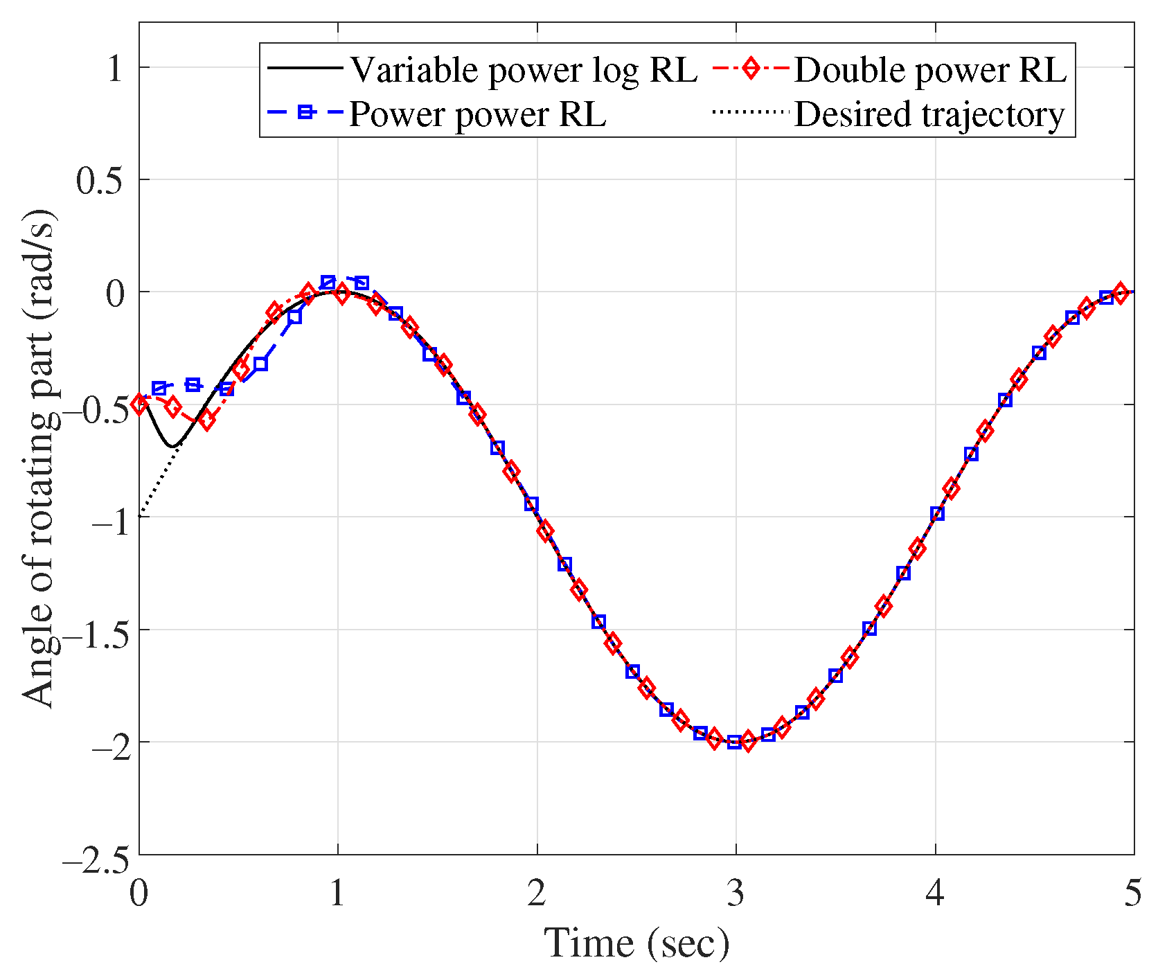
| Group 2 | New RL | 0.10/0.16 | 0.20/0.21 | 0.04/0 | 0.015/0.001 |
| Douple power RL | 0.14/0.24 | 0.63/0.61 | 0.21/0.11 | 0.18/0.03 | |
| Power RL | 0.19/0.34 | 0.76/1.32 | 0.22/0.13 | 0.16/0.06 | |
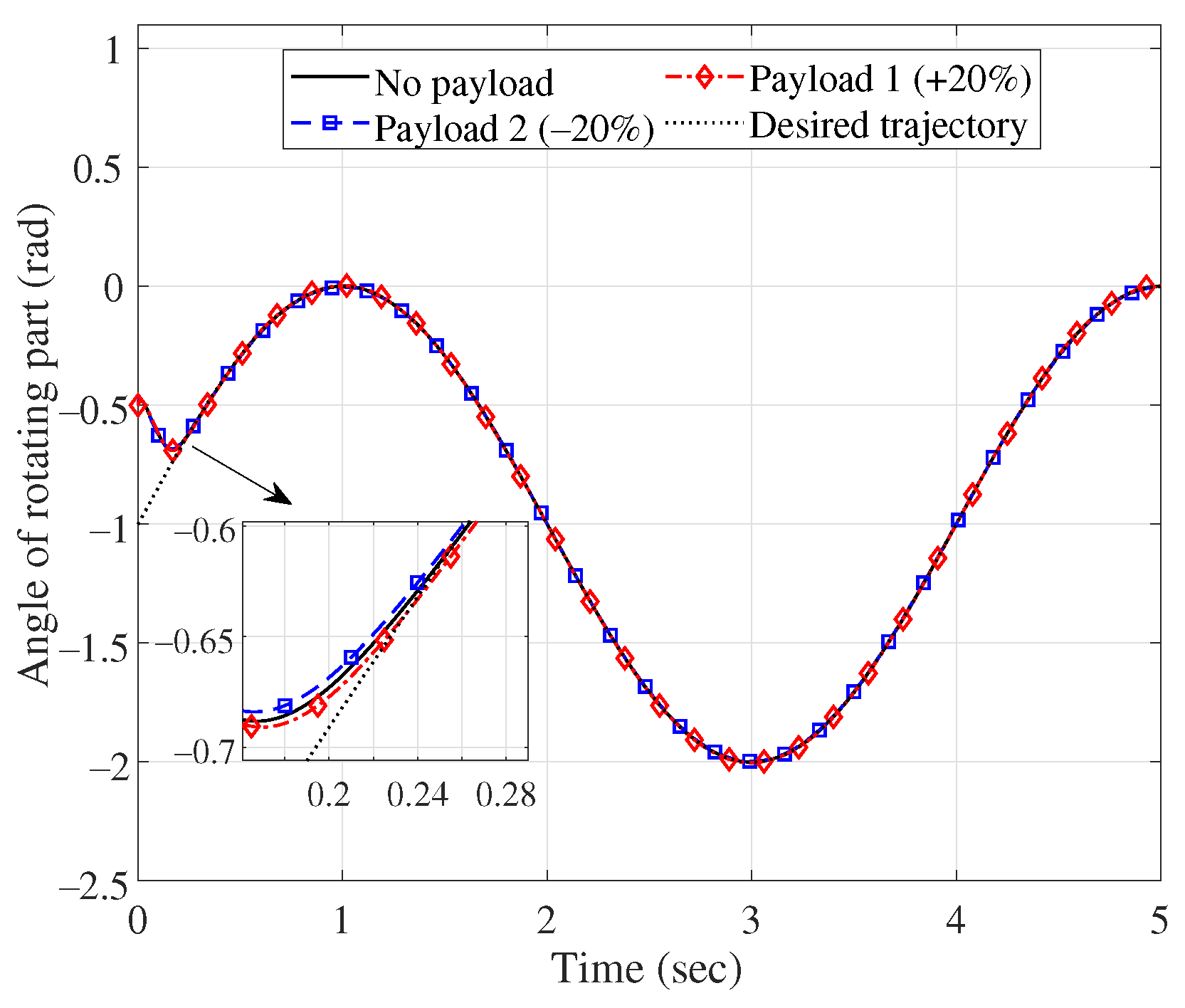
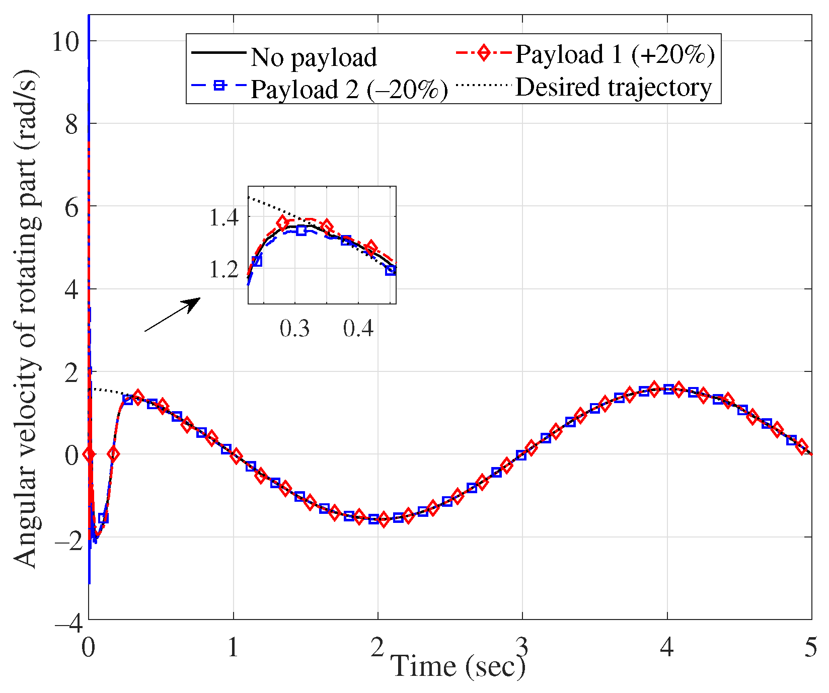
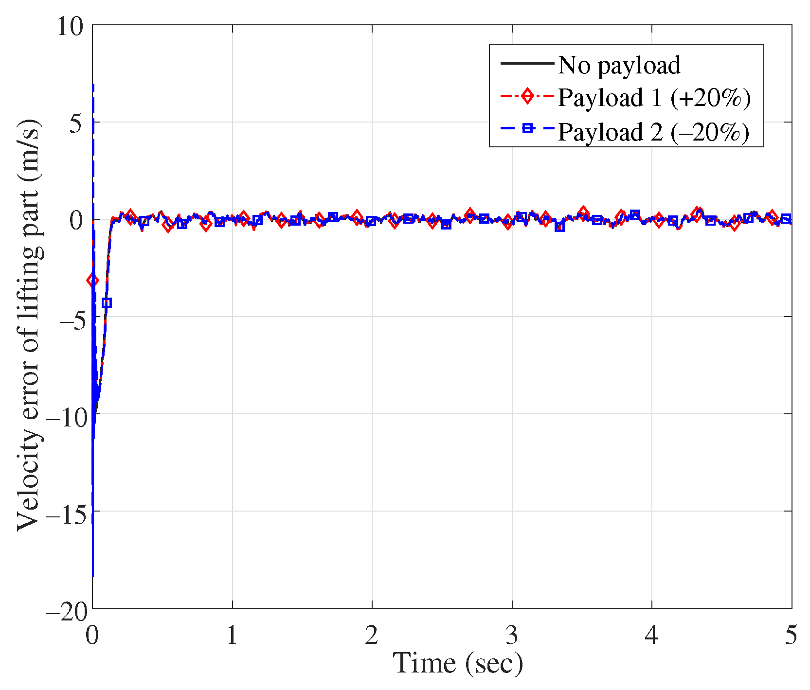
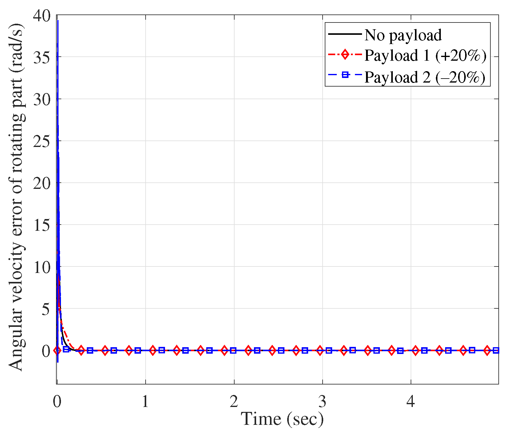
| Group 3 | No payload | 0.10/0.16 | 0.20/0.21 | 0.04/0 | 0.015/0.001 |
| Payload 1 | 0.11/0.16 | 0.21/0.21 | 0.05/0 | 0.018/0.003 | |
| Pyaload 2 | 0.12/0.16 | 0.21/0.21 | 0.05/0 | 0.017/0.002 | |
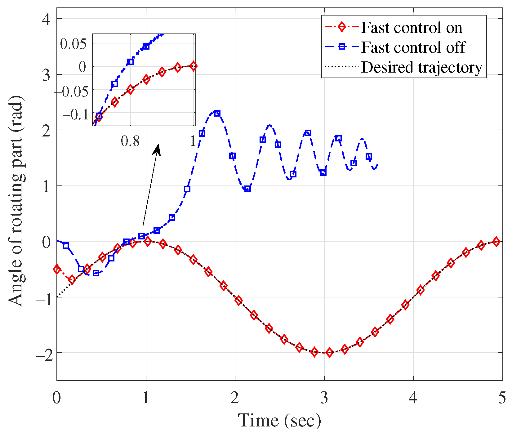
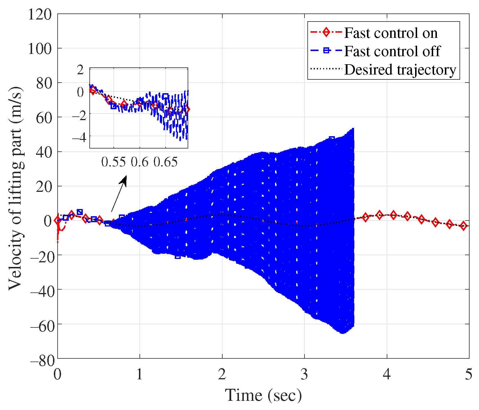
| Fast control on | 0.10/0.16 | 0.20/0.21 | 0.04/0 | 0.015/0.001 | |
| Group 4 | Fast control off | n/a | n/a | n/a | n/a |
Disclaimer/Publisher’s Note: The statements, opinions and data contained in all publications are solely those of the individual author(s) and contributor(s) and not of MDPI and/or the editor(s). MDPI and/or the editor(s) disclaim responsibility for any injury to people or property resulting from any ideas, methods, instructions or products referred to in the content. |
© 2023 by the authors. Licensee MDPI, Basel, Switzerland. This article is an open access article distributed under the terms and conditions of the Creative Commons Attribution (CC BY) license (https://creativecommons.org/licenses/by/4.0/).
Share and Cite
Guo, Y.; Xu, S.; Chen, H.; Zheng, H.; Hao, Z.; Wang, Z. Rapid Robust Control of a Marine-Vehicle Manipulator with Series Elastic Actuators Based on Variable Power Log Reaching Law. J. Mar. Sci. Eng. 2023, 11, 474. https://doi.org/10.3390/jmse11030474
Guo Y, Xu S, Chen H, Zheng H, Hao Z, Wang Z. Rapid Robust Control of a Marine-Vehicle Manipulator with Series Elastic Actuators Based on Variable Power Log Reaching Law. Journal of Marine Science and Engineering. 2023; 11(3):474. https://doi.org/10.3390/jmse11030474
Chicago/Turabian StyleGuo, Yufei, Shengyue Xu, Hao Chen, Hao Zheng, Zhiqiang Hao, and Zhigang Wang. 2023. "Rapid Robust Control of a Marine-Vehicle Manipulator with Series Elastic Actuators Based on Variable Power Log Reaching Law" Journal of Marine Science and Engineering 11, no. 3: 474. https://doi.org/10.3390/jmse11030474
APA StyleGuo, Y., Xu, S., Chen, H., Zheng, H., Hao, Z., & Wang, Z. (2023). Rapid Robust Control of a Marine-Vehicle Manipulator with Series Elastic Actuators Based on Variable Power Log Reaching Law. Journal of Marine Science and Engineering, 11(3), 474. https://doi.org/10.3390/jmse11030474