Article

Modelling Manoeuvrability in the Context of Ship Collision Analysis Using Non-Linear FEM

Faculty of Mechanical Engineering and Naval Architecture, University of Zagreb, 10000 Zagreb, Croatia
*
Author to whom correspondence should be addressed.
J. Mar. Sci. Eng. 2023, 11(3), 497; https://doi.org/10.3390/jmse11030497
Submission received: 2 February 2023 / Revised: 17 February 2023 / Accepted: 23 February 2023 / Published: 25 February 2023
(This article belongs to the Special Issue Ship Collision Risk Assessment)

Abstract

:
Ship collisions are rare events that may have a significant impact on the safety of people, ships, and other marine structures, as well as on the environment. Because of this, they are extensively studied but events that just precede collision are often overlooked. To rationally assess collision risks and consequences, a ship’s trajectory, and consequently the velocity and collision angle, should be known. One way to achieve this is through accurate modelling of ship manoeuvrability in collision analysis using non-linear FEM (NFEM). The Abkowitz manoeuvring model is implemented in the LS-Dyna software code and is therefore coupled with FEM calculations. Hydrodynamic forces are calculated in each time step of the LS-Dyna calculation and added to the FE model continuously through calculation. The accuracy of the calculations depends on the choice of and values of hydrodynamic derivatives from the Abkowitz model. Abkowitz’s model derives hydrodynamic forces in the Taylor expansion series to provide hydrodynamic derivatives. The application of the procedure is sensitive on higher-order Taylor series members. This article reviews different sets of hydrodynamic derivatives available for the KVLCC2 ship. Each of them is incorporated into the LS-Dyna NFEM solver by a user-made Fortran subroutine, with standard Zigzag and turning manoeuvres simulated and results compared with the experimental tests. As a result, the optimal selection of hydrodynamic derivatives is determined, laying a foundation for assessing the risk of ship collision due to different ship manoeuvres prior to the collision itself.

1. Introduction

1.1. General Overview

Ship collision is one of the most extensively studied fields regarding ship dynamics. The consequences of ship collisions can be devastating and lead to serious human injuries or cargo damage [1]. When analysing ship collisions, the mechanics of collision are usually divided into external dynamics and the internal mechanics of the ship [2]. The internal mechanics of ship collisions focus on ship structure response during the collision. This area has been thoroughly analysed over the last decade and can be divided into four different categories: finite element methods, empirical methods, experimental methods, and simplified analytical methods.
Finite element methods approach this subject by focusing either on modelling local parts of the structure [3] or assessing the full model of collision [4]. While this is the most popular method due to its low cost and rising computational power, it may sometimes prove to be challenging for yielding accurate results [5]. The use of empirical methods is the oldest approach to solving these problems, with some of the models developed over a half-century ago [6]. While they proved to be valid for high-energy collision cases, significant scatter appeared for collisions with lower energy or high plastic deformation. While experimental methods are often regarded as the most accurate ones [7], they can be quite costly and require significant time. Lastly, simplified analytical methods present the quickest approach for solving ship collisions, with the major assumption that neither of the internal structural parts interacts with one another. A detailed study comparing the analytical method with the finite element method [8] raised concern that simplified analytical methods cannot accurately predict such a highly complex case.
The external dynamics of the ship are less examined due to the high computational demands on coupling the water domain with the structure domain. One of the most proven methods of analysing external dynamics is a rigid body program called MCOL [9], developed for ship collision studies and based on large rotational formulation. This method is successfully implemented into the finite element software LS-DYNA and tested on various studies. A correlation between MCOL and the ALE approach [10] was made and it proved a good overlap between the two approaches with a significant reduction of time while using MCOL. The problem with MCOL was instability after a longer period of time [11], which reduces the application of MCOL in long, transient simulations of manoeuvrability. A different approach was proposed by directly implementing manoeuvrability equations for surge, sway, and yaw into LS-DYNA [12] and running the collision, but without evaluation of manoeuvrability prior to the ship collision.
Ship manoeuvrability equations can be derived from numerous mathematical models. Generally, they are estimated by either CFD-based or system-based methods [13]. CFD-based methods are the most proven numerical methods used to determine hydrodynamic derivatives, but are not feasible for simulations that last longer than a few seconds due to the enormous computational power required. On the other hand, the system-based approach solves the equation of motion for every time step and can be implemented together with the structural part of the analysis. While simpler mathematical models for system-based methods are kinetic models, their accuracy is insufficient to describe complex manoeuvrability motion. Thus, two main dynamic models are commonly used in describing ship motion. The first model describes ship equations by decomposing hydrodynamic force into hull, rudder, and propeller components, and it is called the MMG model [14]. The second, the Abkowitz model, considers the hull, propeller, and rudder as one rigid body [15]. The regression model, which treats the manoeuvring ship as one entity, may be represented as the Taylor series in kinematic and geometrical variables. While the MMG model offers more detailed information on all of the forces, the Abkowitz model proved to correlate well with the experiments and is more suitable for incorporation into finite-element code. By expanding forces into Taylor series, the optimisation of each member is possible by numerous optimisation techniques, such as [16] where the original hydrodynamic coefficient was optimised for ship manoeuvring in confined water.
The aim of this research is to implement already defined hydrodynamic derivatives for the analysis of ship manoeuvrability into the LS-DYNA code while exploring numerous options for Taylor series expansion and corresponding hydrodynamic forces and how they influence ship behaviour during different manoeuvres such as Zigzag and turning, among others. Finally, different manoeuvres will be explored based on the energy calculation to see how it is possible to reduce damage in a collision by choosing the right manoeuvres. The structure of the article is presented in the Table 1.

1.2. Hydrodynamic Derivatives

The aim of this research is to implement and couple the manoeuvrability hydrodynamic forces with FEM. The KVLCC2 ship is an oil tanker that was chosen due to its availability of both hull form geometry and hydrodynamic derivatives required for the calculation of hydrodynamic forces. Parameters for the KVLCC2 ship are presented in Table 2.
Hydrodynamic derivatives are related to the local coordinate system presented in Figure 1. The ship is described by local coordinate system O-XYZ, where u, v, and r represent surge velocity, sway velocity, and yaw rate, respectively, while ψ is the heading angle and δ is the rudder angle.
Hydrodynamic forces acting on a ship in the X–Y plane only can be written according to Newton’s law:
m ( u ˙ v r x G r 2 ) = F x      
m ( v ˙ + u r + x G r ˙ ) = F y      
I z r   ˙ + m x G ( v ˙ + u r ) = F N      
where m is the ship mass; xG is the longitudinal coordinate of the ship gravity centre; IZ is the moment of inertia about the Z axis; u ˙ , v ˙ , and r   ˙ represent accelerations in surge, sway, and yaw direction, respectively; and Fx, Fy, and FN are longitudinal force, transverse force, and yaw moment, respectively. Right-side forces and moments can be approximated by expanding the Taylor series of hull forces into the following form:
F x = X u u + X v v + X r r + X δ δ + X r δ r δ = X u u + X v v + X r r + X δ + X r δ . .
where Xu, Xv, Xr, Xδ, and Xrδ represent coefficients called Hydrodynamic Derivatives which are dependent on their variable marked in their respective index.

1.2.1. Hydrodynamic Set 1

The first set of hydrodynamic forces is provided by ABS [17]. This set of hydrodynamic forces has the lowest Taylor expansion series of all the chosen sets, second order, which makes it the simplest one.
F x = a 2 + b 2 η + c 2 η 2 + X v v v 2 + X r r r 2 + X v r v r + X δ δ δ 2 + X v δ v δ + X r δ r δ
F y = Y v v + Y v | v | v | v | + Y r r + Y | v | r | v | r + Y δ δ
F N = N v v + N v | v | v | v | + N r r + N | v | r | v | r + N δ δ + N v δ v δ + N r δ r δ    
From Equation (5), the axial force is defined throughout the propulsion ratio η , which is described with the following equation:
η = V u
where V is the described commanding velocity and u is the current axial velocity.

1.2.2. Hydrodynamic Set 2

The second set of hydrodynamic forces is taken from [18]. This set consists of some higher-order terms of Taylor expansion, such as a cubic member for sway velocity with terms for yaw rate r, rudder turning rate δ being included for the quadratic Taylor expansion order, and a combined term for both rudder deflection, yaw rate, and sway velocity. The equations are:
F x = X u Δ u + X u u Δ u 2 + X v v v 2 + X r r r 2 + X v r v r + X δ δ δ 2 + X v δ v δ + X r δ r δ    
F y = Y v v + Y v v v 2 + Y v v v v 3 + Y r r + Y r r r 2 + Y r r r r 3 + Y v r v r + Y δ δ δ 2 + Y v δ v δ + Y r δ r δ    
F N = N v v + N v v v 2 + N v v v v 3 + N r r + N r r r 2 + N v r v r + N δ δ δ 2 + N v δ v δ + N r δ r δ    

1.2.3. Hydrodynamic Set 3

The final set of hydrodynamic forces is taken from [19], where additional terms regarding cubic Taylor series expansion are included:
F x = X u Δ u + X u u Δ u 2 + X v v v 2 + X δ δ + X r r + X r r r 2 + X v r v r + X δ δ δ 2 + X v δ v δ + X r δ r δ + X r r δ   r r δ + X v v δ v v δ + X δ δ u δ δ u
F y = Y v v + Y v v v 2 + Y v v v v 3 + Y r r + Y r r r 2 + Y r r r r 3 + Y v r v r + Y δ δ δ 2 + Y v δ v δ + Y r δ r δ + Y v v δ v δ + Y v v r v v r + Y δ δ δ δ 3 + Y u δ u δ    
F N = N v v + N v v v 2 + N v v v v 3 + N r r + N r r r 2 + N v r v r + N δ δ δ 2 + N v δ v δ + N r δ r δ + N r r r r 3 + N δ δ δ δ 3 + N v δ δ v δ 2 + N v v r v v r

1.3. Non-Dimensional to Dimensional Form of Hydrodynamic Coefficients

Often in problems regarding fluid dynamics involving numerous physical quantities, the non-dimensional form is used. This technique enables simplification and better understanding of correlations between numerous parameters. While Equations (5)– (14) are written in dimensional form, hydrodynamic derivatives for all three sets for KVLCC2 ship are provided in a non-dimensional form, as shown in Table 3.
Dimensional analysis [20] is applied for coefficients presented in Table 3 in the SI unit of system, converting coefficients into Newtons for surge and sway and Nm for yaw. Data for dimensioning all the coefficients for the KVLCC2 ship is presented in Table 4.

2. LOADUD Subroutine Implementation

After the conversion from non-dimensional to dimensional form, a set of Equations (5)–(14) can be implemented to the Fortran code. The hydrodynamic forces are calculated and applied to the centre of gravity of the ship. As seen from Equation (4), derivatives are based on either one variable or a combination of multiple variables, so variables from LS-DYNA should be imported. Each variable from LS-DYNA, such as displacement, velocity, and rotational velocity, is defined in the global coordinate system.
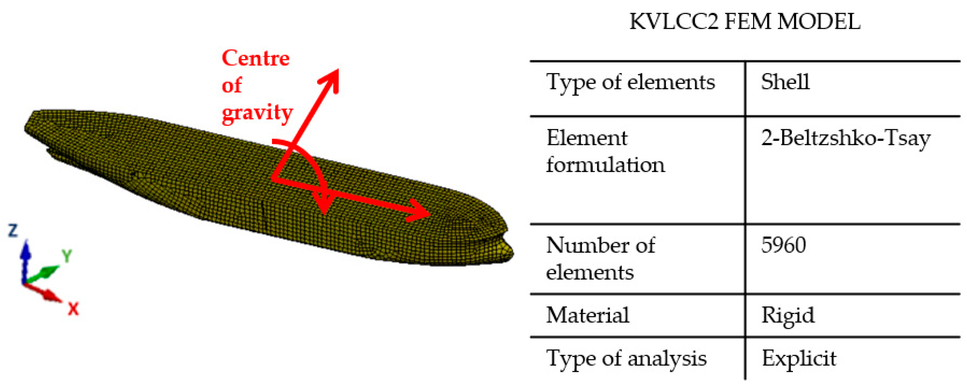
The simplified rigid body ship model is designed in order to quickly assess ship trajectory. The ship consists of 5960 shell elements with applied rigid material characteristics. Rigid body calculation requires low computational time and enables correct energy assessment during collision. The rigid body model, global coordinate system, and orientation of hydrodynamic forces is presented in Figure 2.
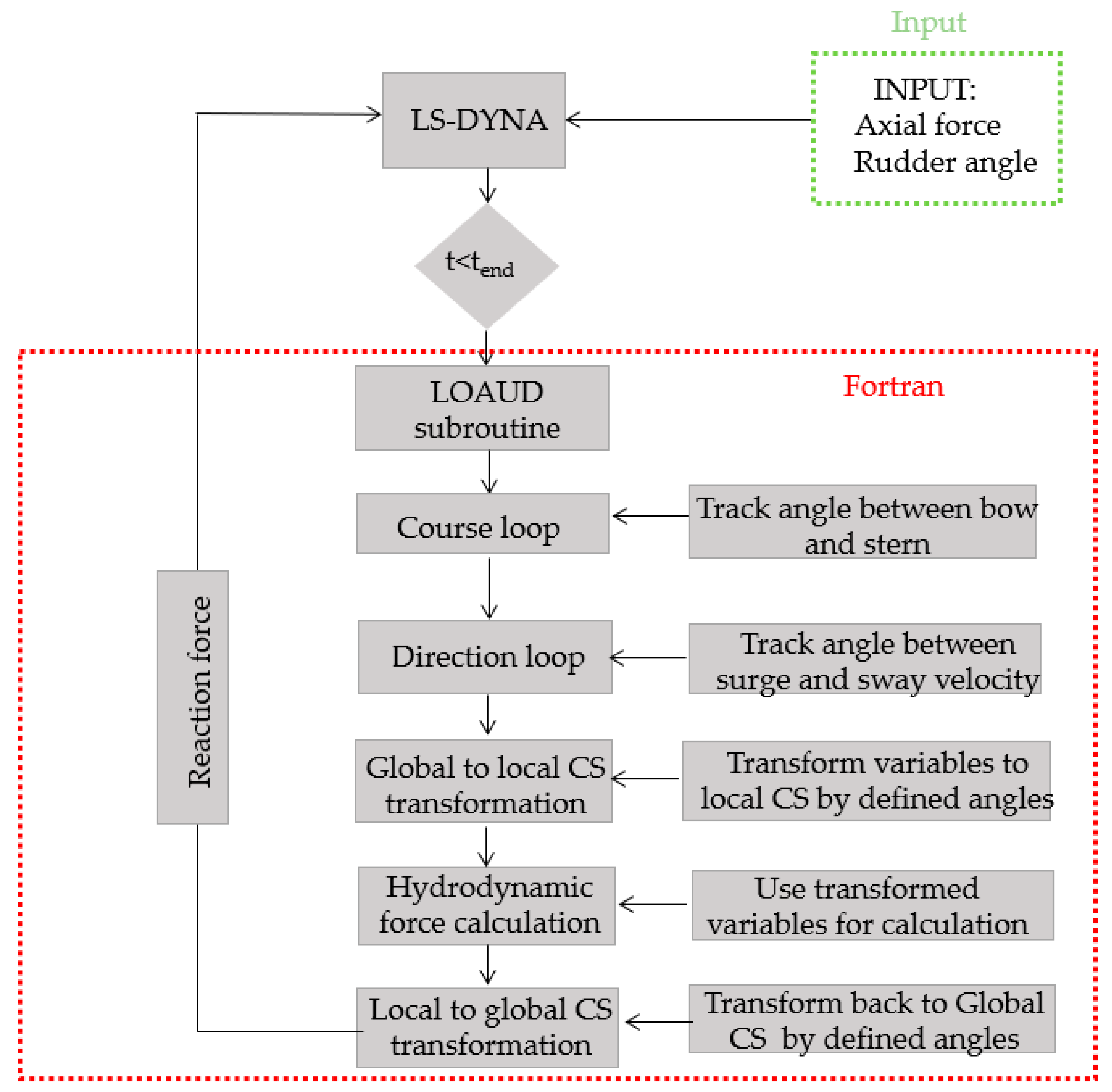
The workflow of simulation is presented in Figure 3. It starts with the LS-DYNA initialisation of calculations and applied initial conditions, which in this case are rudder turning rate and initial axial force. Rudder turning rate changes over a period of time, and it is defined as a table value and is incorporated into Fortran as a variable. With this, the turning manoeuvre of the ship is initialised and hydrodynamic forces for a surge and yaw can start to be calculated. In addition, initial axial force is implemented since the Abkowitz numerical models are defined for the commanding velocity. If initial velocity had been applied, the approaching speed before manoeuvre would be slower than needed, so, instead, propulsion force defined as a cubic function that depends on axial velocity was applied:
F a p p l i e d = 5430 · u 3 36905 · u 2 + 258772 · u 63612
where u (m/s) is surge velocity. Propulsion force was extrapolated by running multiple simulations for the ship to reach axial velocity, 7.973 m/s.
For this reason, the analysis starts with an initial period of 4000 s of simulation time required for the ship to reach the wanted surge velocity. After initialisation of the calculation by LS-DYNA, calculated variables such as velocity and rotational velocity are transferred to the user subroutine to calculate hydrodynamic forces. The fundamental problem here is that LS-DYNA operates in a global coordinate system while Equations (5)– (14) relate to a local coordinate system. Because of this, two additional loops are implemented. First, the LS-DYNA variables enter the Course loop, which is determined by the angle between the stern and bow while considering each quadrant. After this, the Direction loop determines the velocity direction in which the ship intends to move. The angles calculated from additional loops are used for the transformation of global variables from LS-DYNA into local ones. After the hydrodynamic forces are calculated, they are converted back to the global coordinate system and implemented into LS-DYNA, where they are applied to the ship C.O.G. The workflow algorithm is summarised in Figure 3.

3. Validation of the Results

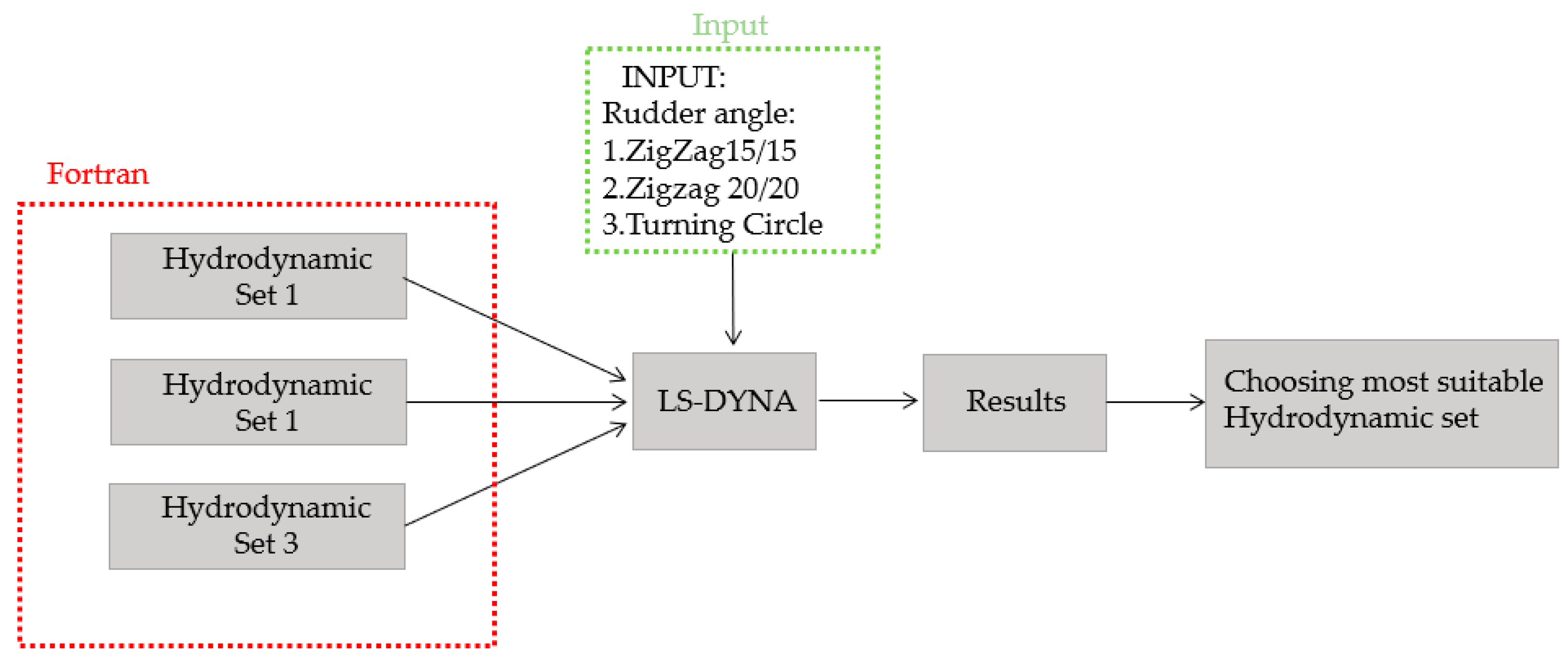
Figure 4 presents the procedure of results validation. Three different sets of hydrodynamic forces presented in Section 1.2. are implemented into the Fortran subroutine and analysed under different manoeuvrability tests: Zigzag 15/15, 20/20, and turning circle. Results were analysed by comparing the velocity, displacement, and forces, with the most suitable Hydrodynamic Set chosen for further application. The execution time for 5000 s of simulation time lasted approximately 240 s of real time.

3.1. Half-Turn Comparison

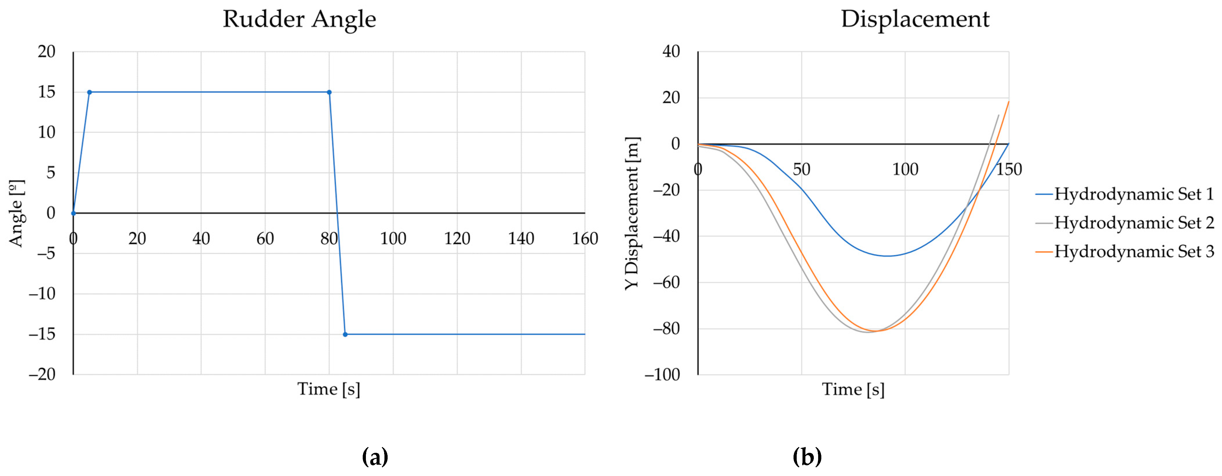
The comparison between three sets of different hydrodynamic derivatives is compared during one half-turn. The turning angle of 15° (half cycle of Zigzag 15/15) is chosen as a referent case.
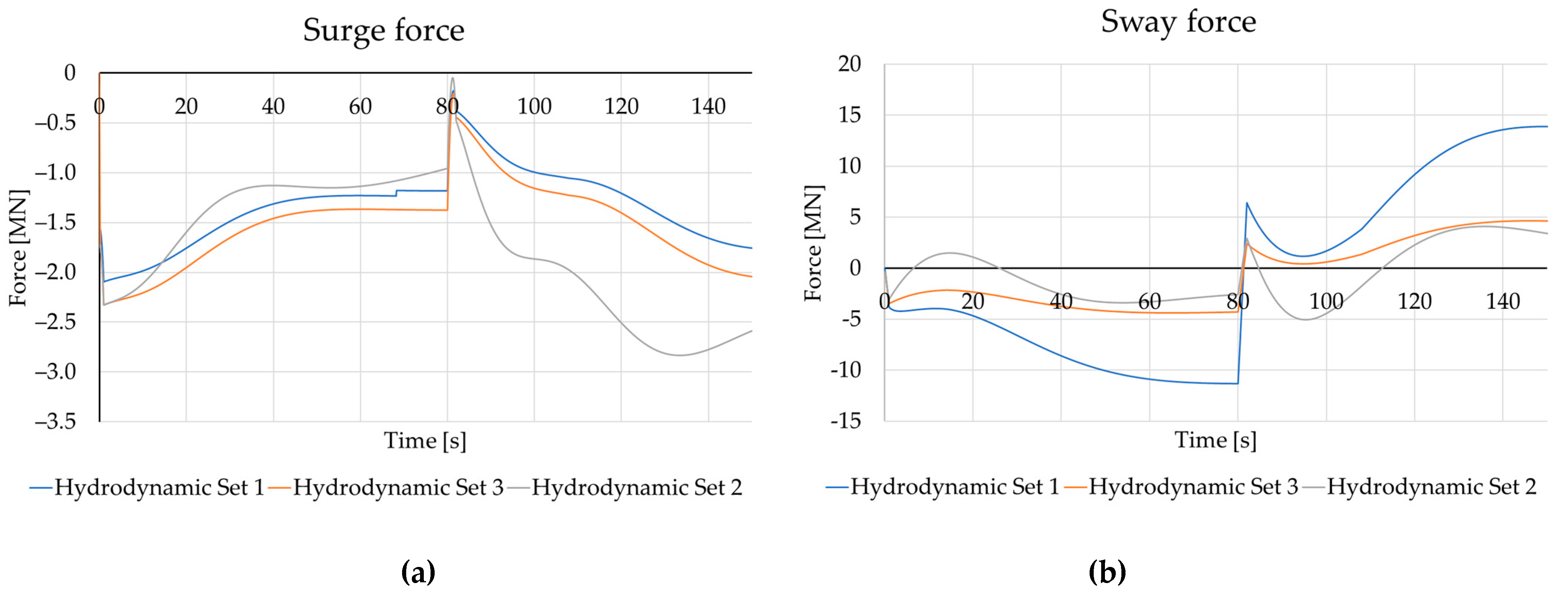
In Figure 5, displacement in the Y direction is presented. While for Hydrodynamic Sets 2 and 3 results differ by no more than 5%, the discrepancy with the first Hydrodynamic Set 1 is clearly visible. This is further evident when examining the forces during the half-turn, as shown in Figure 6.
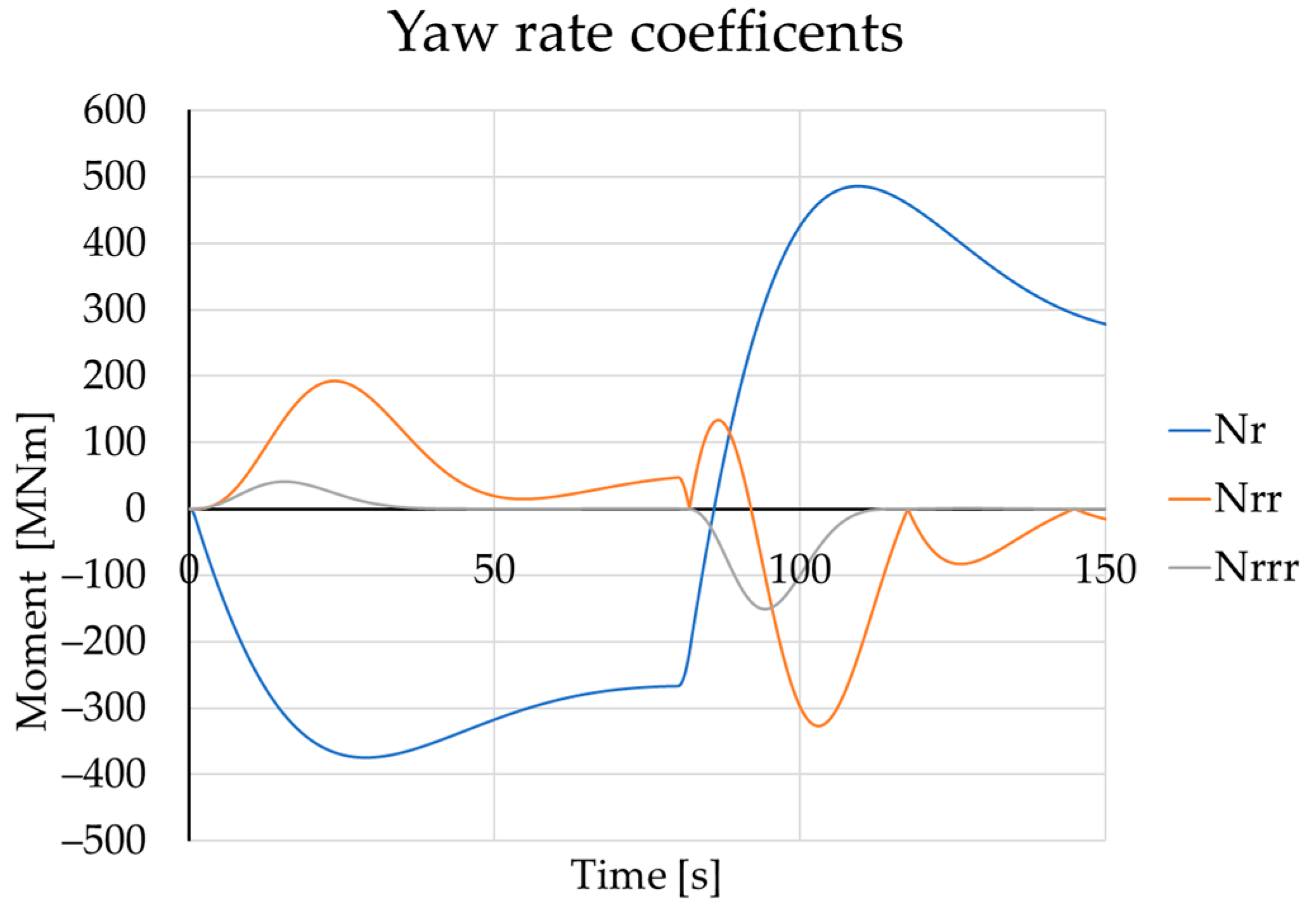
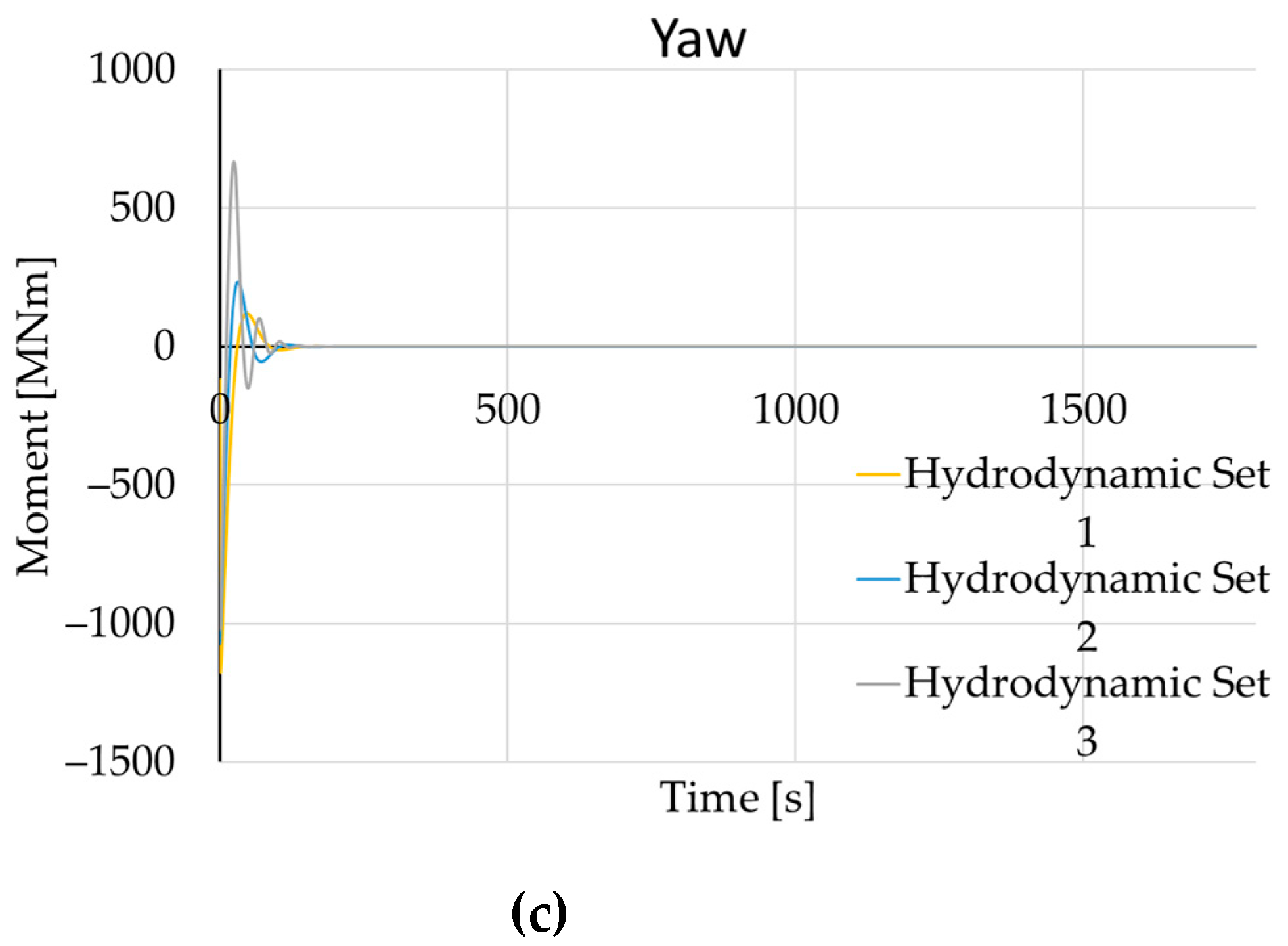
Forces during the half-turn presented in Figure 6 showed good correlation between Hydrodynamic Sets 2 and 3 for sway force and yaw moment, which is expected. However, for Hydrodynamic Set 1, both displacement and forces showed a big discrepancy opposed to the other two cases. Even though it is very hard to analyse three coupled equations, Figure 6c showed a big spike in the yaw moment for Hydrodynamic Set 1 during the rudder turning angle change. Because of this, yaw rate members are separately analysed with respect to their values over time.
Separate analysis is shown in Figure 7. The yaw rate coefficients showed the biggest spike between 80 s and 100 s, which is a time when rudder deflection and consequently rotational velocity changes sign. While Hydrodynamic Set 1 only has a linear Taylor member for yaw rate, the other sets have higher-order members which are not negligible. Higher-order members Nrr and Nrr have negative values and, thus, dampen the yaw moment and cause a bigger turning radius. This is the cause of a higher value of sway force, which can be seen in Figure 6b.

3.2. Turning Circle 35°

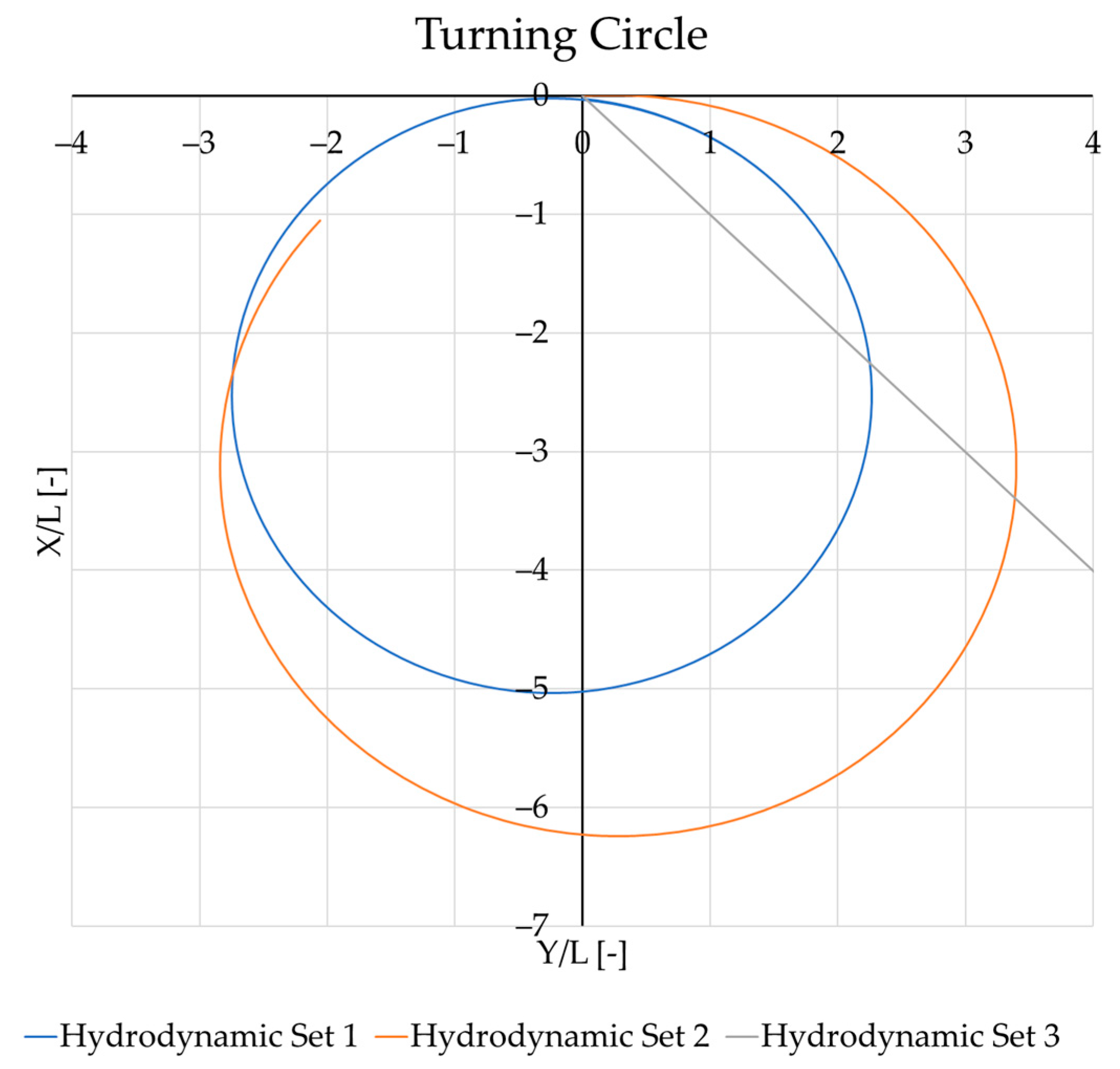
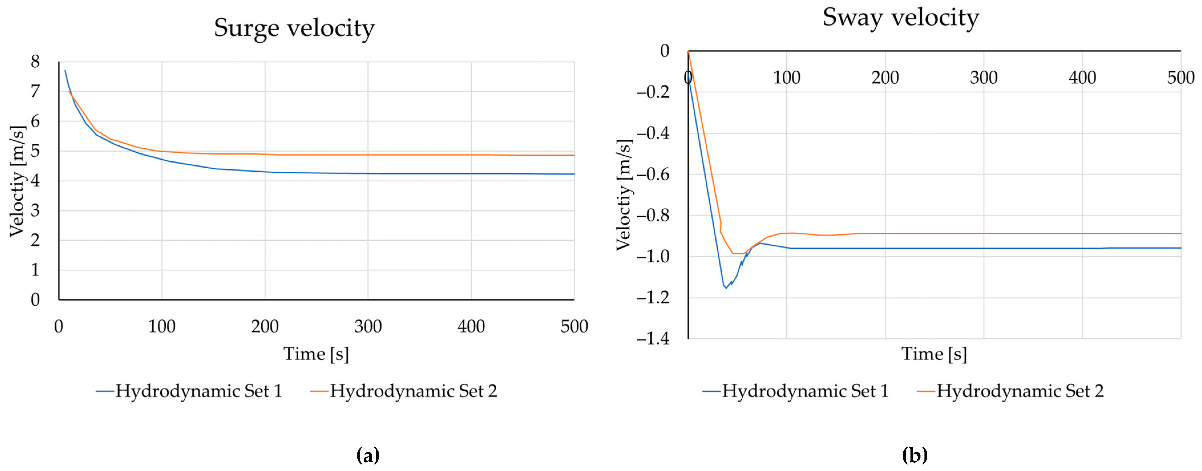
The turning circle is analysed, with the duration of the whole cycle equal to 2000 s. The rudder turning rate is constant over that period, while the time step prescribed for explicit analysis is varied between 1 s and 0.01 s to see if the LS-DYNA time step influences results. The results of displacement over a ship length are shown in Figure 8. with the similar behaviour between Hydrodynamic Sets 1 and 2 evident. While the turning circle for Hydrodynamic Set 1 remains symmetric and makes an ideal circle which is not realistic, the results for Hydrodynamic Set 2 show asymmetrical behaviour. A problem occurs with Hydrodynamic Set 3, which does not make the circle test correctly but instead continues to translate linearly. It can be concluded that only Hydrodynamic Set 2 realistically describes ship movement.
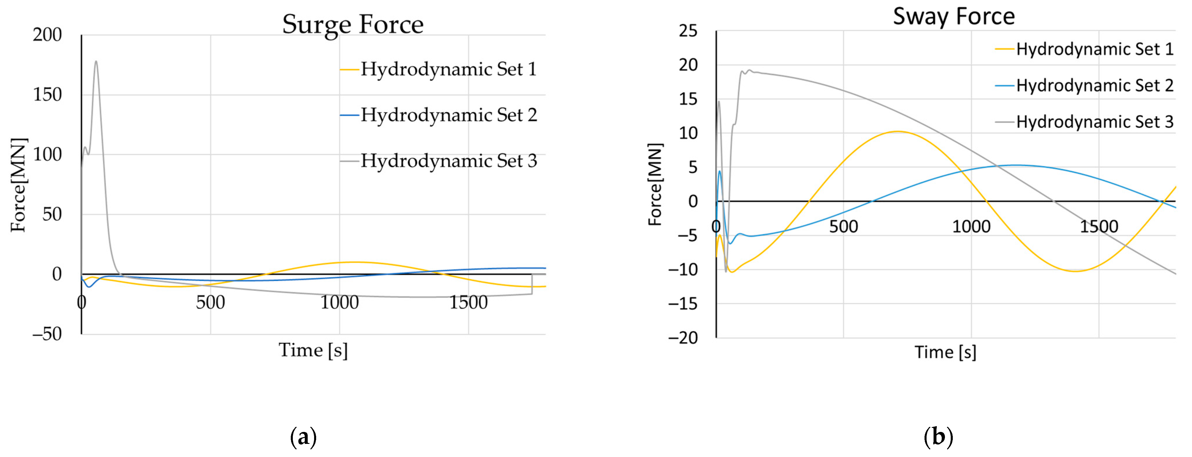
Forces during the turning circle test are shown in Figure 9. As can be seen from Figure 9a, a spike in surge force occurs for Hydrodynamic Set 3. This is the cause of a sudden turn and appearance of rotational velocity where numerical rounding-off proved to be crucial. The coefficient regarding yaw rate reached a peak value in the equation for surge motion while the yaw moment remained too small opposed to the surge force and caused the ship to move forward instead of making a turning cycle.
As Hydrodynamic Set 3 completely miscalculated the turning cycle, further comparisons will be made for Hydrodynamic Sets 1 and 2. Figure 10 compares the velocity in both directions, as well as the rotational velocity for both cases.

3.3. Validation on Zigzag 20/20 Test

While Hydrodynamic Set 1 did not over-predict sway force and yaw moment due to a lack of higher-order Taylor members and Hydrodynamic Set 3 proved to be prone to spikes during a sudden appearance of rotational velocities, Hydrodynamic Set 2 was compared with the results from [18] for Zigzag 20/20.
The results from Figure 11 show good overlap between the two cases where the numerical simulation has a delay, probably due to underpredicting the yaw moment.

4. Prediction of Ship Collision Consequences

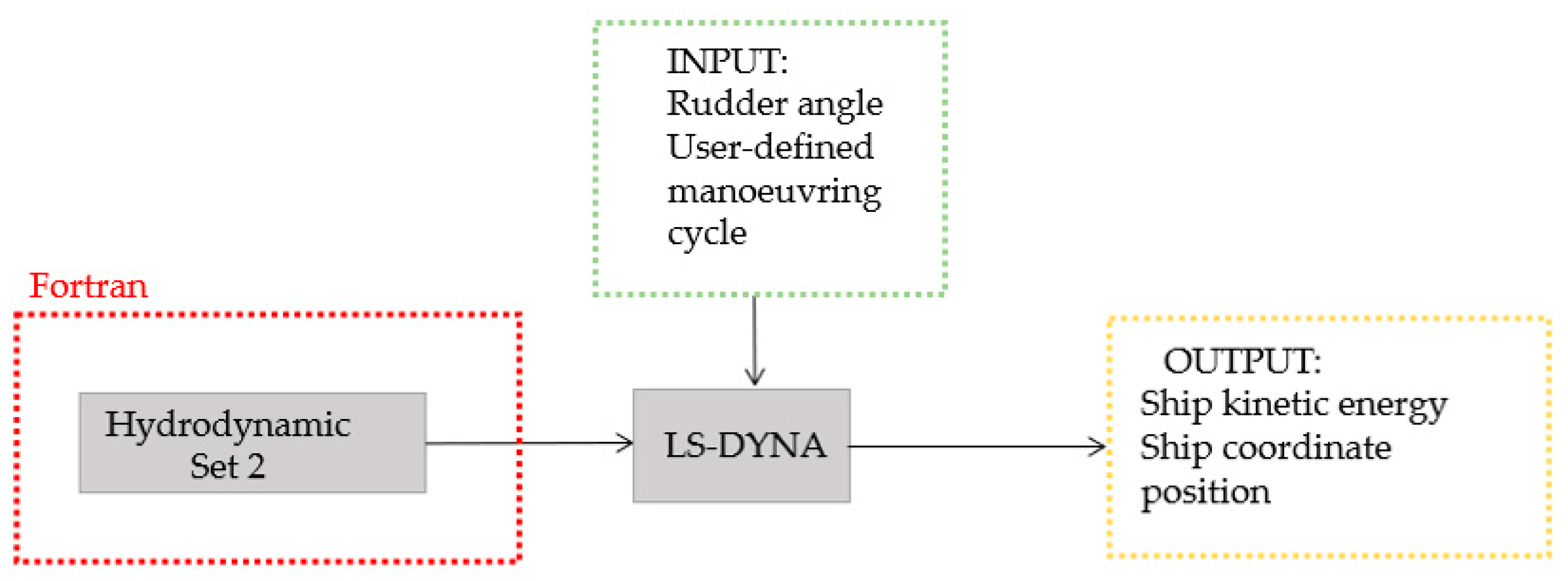
As the optimal Hydrodynamic Set is established (Hydrodynamic Set 2), a numerical procedure is applied for rapid ship collision assessment. As shown in Figure 12 below, Hydrodynamic Set 2 is implemented into the Fortran subroutine, which is adopted to calculate the position for two ships instead of only one. User-defined manoeuvres can be introduced into LS-DYNA as table values, the same as before. This procedure can provide information on ship kinetic energy as well as ship coordinate position, with the execution time of the analysis being in the order of a few minutes, depending on the simulation time.

4.1. Kinetic Energy as a Function of Ship Manoeuvring

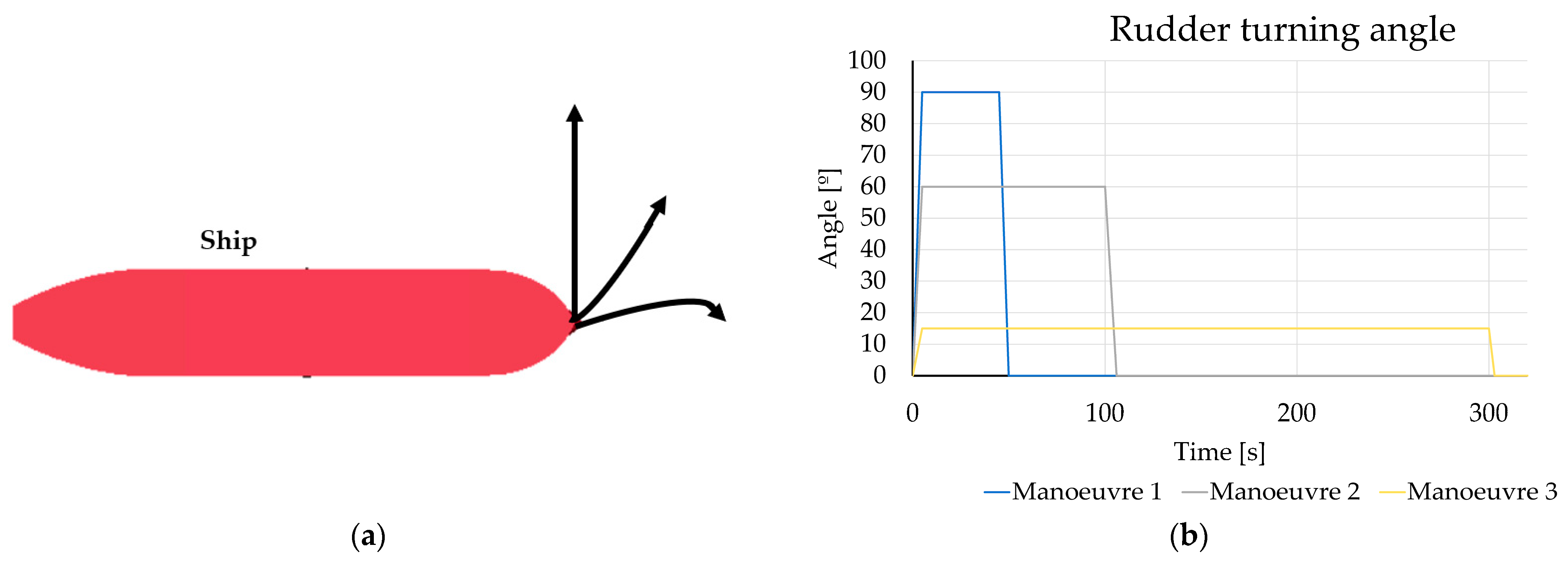
While collision outcome heavily depends on the angle of attack and ship structure, it also depends on velocity and, consequently, total kinetic energy. By assessing the potential velocity decrease due to different manoeuvres, kinetic energy can be estimated. Implementation of the three different manoeuvres was tested in order to see how kinetic energy decreased over time, Figure 13. Manoeuvre 1 had a sharp 90° turn over a period of 50 s, Manoeuvre 2 had a 60° turn over a period of 100 s, while Manoeuvre 3 has the slightest turn with 15° over 300 s.
The change of kinetic energy for each ship manoeuvre can be seen in Figure 14. The diagram shows that a rudder turning rate of 90° (Manoeuvre 1) causes a sudden drop of kinetic energy during its turn, even though the duration is lower than in the rest of the cases. For Manoeuvre 2, the total remaining kinetic energy is higher than that for Manoeuvre 1 but significantly lower than for the last manoeuvre, Manoeuvre 3. Even though the conclusions stated are obvious, the retaining value of kinetic energy does not behave linearly, so it is almost impossible to predict kinetic energy after the manoeuvre without calculating the hydrodynamic forces.
The presented approach can be used for quickly assessing ship speed reduction and kinetic energy retaining, which could be further used in analytical methods such as [6].

4.2. Multiple Ship Analysis

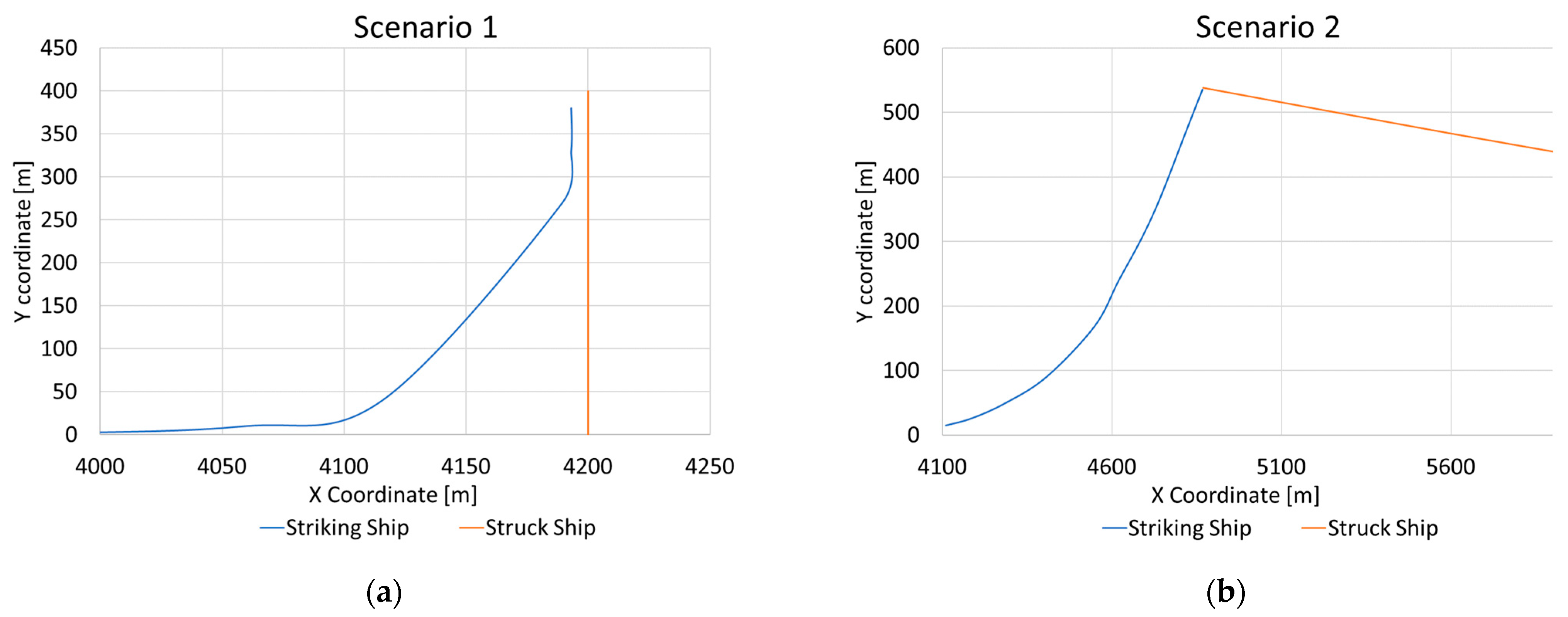
The implementation of hydrodynamic forces enables a more advanced analysis of a ship’s external dynamics prior to a collision. It is possible to include multiple ships in the analysis while incorporating simultaneous manoeuvres of these ships. If multiple ships are introduced into the analysis, the appropriate numerical workflow should be incorporated, that is, an additional parallel loop should be added to the existing one in the numerical workflow algorithm, Figure 3. For a second ship, two scenarios were analysed. Figure 15a shows Scenario 1 where Striking Ship is manoeuvring to turn left under constant 60° over 100 s, while Struck Ship is maintaining a straight sailing direction. In Figure 15b, both ships are performing manoeuvres. Striking Ship is making a left-turn manoeuvre under 90° for 100 s, while Struck Ship is making a right-turn manoeuvre under constant 15° for also 100 s.
Implementing multiple ships’ kinematics into the same analysis and tracking ships in a coordinate system becomes possible. By introducing any rudder turning angle as a curve function, the Fortran subroutine calculates hydrodynamic forces and returns them to LS-DYNA as a nodal load. Based on this, LS-DYNA calculates displacement, velocity, and associated energy in the next time step. This enables the user to track a ship’s coordinate position, current velocity, and kinetic energy at any moment. The biggest advantage of this is that the calculation lasts less than 300 s of real time, which can enable the user to run multiple scenarios and develop a better understanding of what is the most effective and what is the least effective manoeuvre in any given circumstance. Coordinate tracking for both scenarios are shown in Figure 16.

5. Discussion and Conclusions

The Abkowitz model was implemented into the finite element solver by using a Fortran subroutine. Three different sets of equations were chosen, provided by [18,19,20], respectively, so different approaches could be tested. For ship modelling, rigid elements were used in order to reduce simulation time. It was shown that transient analysis is sensitive to different terms of the Taylor expansion. For the first set, Hydrodynamic Set 1, no term of the Taylor series higher than a quadratic was included, and this showed that behaviour during half-turning in Zigzag 15/15 is not physical. As the hydrodynamic moment rose, an order of magnitude higher than in the other two sets occurred. On the other hand, the most complete set of hydrodynamic equations, Hydrodynamic Set 3, showed that sudden spikes in either of the 3DOF equations occurred due to a sudden increase in rotational speed, which led to a high value in yaw rate terms. The second set of derivatives, Hydrodynamic Set 2, proved to have the most stable behaviour of all. While this implementation of hydrodynamic equations into the finite element software expands the possibility of a testing collision scenario with moving models, it also opens the possibility to analyse manoeuvres and their outcomes while providing information about manoeuvres in less than a minute of calculation time.
An analysis of kinetic energy during manoeuvres can be a great tool for obtaining information about the minimal rudder turning angle needed to avoid or minimise a collision. Moreover, kinetic energy obtained by these equations can be used in experimental methods for collision studies which are useful for quick prediction of ship damage. As shown in Section 4, this tool provides the possibility of including multiple ships into an analysis and determine not just the collision outcome, that is, will they collide or not, but at which specific point will they collide.
The manoeuvre outcome, the resulting kinetic energy after the performed manoeuvre, and the specific point at which ships are going to collide heavily depend on accuracy in solving hydrodynamic equations, as well as in terms of the equations themselves. For future work, the implementation of filters for solving sudden spikes in equations should be considered. Moreover, the 3DOF of models are useful for quick assessment but in order to accurately incorporate it into complete ship collision analysis, additional 3DOF should be implemented. Additional 3DOF represents heave, pitch, and roll motions, which are not determining factors in manoeuvrability analysis but can be significant in collisions from an external dynamics point of view, and also for internal mechanics calculations as they affect the contact zone. Roll and heave motion significantly depend on the position of the contact force in regard to the struck ship centre of gravity. Another possibility that could be investigated is the implementation of the MMG model instead of the Abkowitz model. The MMG model could provide greater control over all three different terms while decomposing forces into three different parts: hull, propeller, and rudder.
By implementing manoeuvrability equations into the finite solver, the foundation has been laid for more complex calculations involving coupling with the non-linear structural analysis and providing a better understanding of the collision event, and not just of its consequences.

Author Contributions

Author Contributions: Š.S.: investigation, methodology, validation, formal analysis, visualisation, writing—original draft preparation and editing. S.R.: investigation, methodology, supervision, writing—review and editing. All authors have read and agreed to the published version of the manuscript.

Funding

This research received no external funding.

Institutional Review Board Statement

Not applicable.

Informed Consent Statement

Not applicable.

Data Availability Statement

Not applicable.

Acknowledgments

This work has been supported by the Croatian Science Foundation within the projects HRZZ IP-2020-02-3420.

Conflicts of Interest

The authors declare that they have no known competing financial interest or personal relationships that could have appeared to influence the work reported in this paper.

Abbreviations

AbbreviationDefinition
ABSAmerican Bureau of Shipping
ALEArbitrary Lagrange-Euler
CFDComputational Fluid Dynamics
FEMFinite Element Method
KVLCC2KRISO Very Large Cruder Carrier 2
LOAUDLoad User-defined
MMGManoeuvring Modelling Group

References

  1. Kuznecovs, A.; Ringsberg, J.W.; Ullal, A.M.; Bangera, P.J.; Johnson, E. Consequence analyses of collision-damaged ships—Damage stability, structural adequacy and oil spills. Ships Offshore Struct. 2022, 1–15. [Google Scholar] [CrossRef]
  2. Liu, B.; Villavicencio, R.; Zhang, S.; Soares, C.G. Guedes Soares, Assessment of external dynamics and internal mechanics in ship collisions. Ocean Eng. 2017, 141, 326–336. [Google Scholar] [CrossRef]
  3. Gao, Z.; Yang, S.; Hu, Z. The Resistance of Ship Web Girders in Collision and Grounding. Math. Probl. Eng. 2014, 2014, 720542. [Google Scholar] [CrossRef] [Green Version]
  4. Tabri, K.; Varsta, P.; Matusiak, J. Numerical and experimental motion simulations of nonsymmetric ship collisions. J. Mar. Sci. Technol. 2010, 15, 87–101. [Google Scholar] [CrossRef]
  5. Ringsberg, J.W.; Amdahl, J.; Chen, B.Q.; Cho, S.-R.; Ehlers, S.; Hu, Z.; Kubiczek, J.M.; Kõrgesaar, M.; Liu, B.; Marinatos, J.N.; et al. MARSTRUCT benchmark study on nonlinear FE simulation of an experiment of an indenter impact with a ship side-shell structure. Mar. Struct. 2018, 59, 142–157. [Google Scholar] [CrossRef] [Green Version]
  6. Minorsky, V.U. An Analysis of Ship Collision to Protection of Nuclear Powered Plant. J. Ship Res. 1959, 3, 1–4. [Google Scholar]
  7. Zhang, S.; Pedersen, P.T.; Villavicencio, R. Internal mechanics of ship collision and grounding. Probab. Mech. Ship Collis. Grounding 2019, 2019, 147–270. [Google Scholar] [CrossRef]
  8. Liu, B.; Pedersen, P.T.; Zhu, L.; Zhang, S. Review of experiments and calculation procedures for ship collision and grounding damage. Mar. Struct. 2018, 59, 105–121. [Google Scholar] [CrossRef] [Green Version]
  9. Le Sourne, H. A ship collision analysis program based on the super-element method coupled with a large rotational ship movement analysis tool. In Proceedings of the International Conference on Collision and Grounding of Ships, Hamburg, Germany, 9–12 September 2007; pp. 131–138. [Google Scholar]
  10. Rudan, S.; Ćatipović, I.; Berg, R.; Völkner, S.; Prebeg, P. Numerical study on the consequences of different ship collision modelling techniques. Ships Offshore Struct. 2019, 14, 387–400. [Google Scholar] [CrossRef]
  11. Rudan, S.; Karačić, J.; Ćatipović, I. Non-linear response of a moored LNG ship subjected to regular waves. Ships Offshore Struct. 2021, 16, 44–57. [Google Scholar] [CrossRef]
  12. Yu, Z.; Amdahl, J.; Storheim, M. A new approach for coupling external dynamics and internal mechanics in ship collisions. Mar. Struct. 2016, 45, 110–132. [Google Scholar] [CrossRef]
  13. Sukas, O.F.; Kinaci, O.K.; Bal, S. Theoretical background and application of MANSIM for ship maneuvering simulations. Ocean Eng. 2019, 192, 106239. [Google Scholar] [CrossRef]
  14. Yasukawa, H.; Yoshimura, Y. Introduction of MMG standard method for ship maneuvering predictions. J. Mar. Sci. Technol. 2014, 20, 37–52. [Google Scholar] [CrossRef] [Green Version]
  15. Jian-Chuan, Y.; Zao-Jian, Z.; Feng, X. Parametric Identification of Abkowitz Model for Ship Maneuvering Motion by Using Partial Least Squares Regression. J. Offshore Mech. Arct. Eng. 2015, 137, 31301. [Google Scholar] [CrossRef]
  16. Du, P.; Ouahsine, A.; Toan, K.T.; Sergent, P. Simulation of ship maneuvering in a confined waterway using a nonlinear model based on optimization techniques. Ocean Eng. 2017, 142, 194–203. [Google Scholar] [CrossRef]
  17. ABS. Guide for Vessel Manouverabitiy; Updated 2017; American Bureu of Shipping: Houston, TX, USA, 2017. [Google Scholar]
  18. Hu, Y.; Yao, J.; Liu, Z.; Song, L. Identification of Ship Hydrodynamic Derivatives Based on LS-SVM with Wavelet Threshold Denoising. J. Mar. Sci. Eng. 2021, 9, 1356. [Google Scholar] [CrossRef]
  19. Mucha, P. On Simulation-Based Ship Maneuvering Prediction in Deep and Shallow Water. Doctoral Thesis, University of Duisburg-Essen, Duisburg, Germany, 2017. [Google Scholar]
  20. Sheeja, J.; Krishnankutty, P. Determination of Linear and Non-linear Hydrodynamic Derivatives of a Surface Ship in Manoeuvring Using CFD Method. In Advances in Visualization and Optimization Techniques for Multidisciplinary Research; Springer: Cham, Switzerland, 2020. [Google Scholar] [CrossRef]
Figure 1. Coordinate system.
Jmse 11 00497 g001
Figure 2. Forces generated with LS-DYNA subroutine.
Jmse 11 00497 g002
Figure 3. Numerical workflow algorithm.
Jmse 11 00497 g003
Figure 4. Procedure of results validation.
Jmse 11 00497 g004
Figure 5. Half-turn simulation: (a) Input turning angle, (b) Comparison of displacement between results for three different Hydrodynamic Sets.
Jmse 11 00497 g005
Figure 6. Comparison between three different hydrodynamic forces: (a) Surge force, (b) Sway force, (c) Yaw moment.
Jmse 11 00497 g006aJmse 11 00497 g006b
Figure 7. Comparison of different-order yaw rate coefficients.
Jmse 11 00497 g007
Figure 8. Turning circle test: Normalised displacement over a ship length in global CS.
Jmse 11 00497 g008
Figure 9. Turning circle test: (a) Surge force, (b) Sway Force, (c) Yaw moment.
Jmse 11 00497 g009aJmse 11 00497 g009b
Figure 10. Turning circle test: (a) Surge velocity, (b) Sway velocity.
Jmse 11 00497 g010
Figure 11. Zigzag 20/20: (a) Sway velocity, (b) Rotational velocity.
Jmse 11 00497 g011
Figure 12. Procedure for rapid analysis of ship collision consequences.
Jmse 11 00497 g012
Figure 13. Ship model: (a) Manoeuvres, (b) Rudder turning angle.
Jmse 11 00497 g013
Figure 14. Kinetic energy over time.
Jmse 11 00497 g014
Figure 15. Scenarios: (a) Scenario 1—Striking Ship making a manoeuvre, (b) Scenario 2—Both ships making manoeuvres.
Jmse 11 00497 g015
Figure 16. Coordinate tracking: (a) Scenario 1, (b) Scenario 2.
Jmse 11 00497 g016
Table 1. Structure of the article.
ChapterDescription
1. IntroductionThe literature research is presented regarding manoeuvrability with an introduction of hydrodynamic forces described by derivatives.
2. LOADUD subroutine implementationThe procedure for implementation of the hydrodynamic forces into the finite element software is described.
3. Validation of the resultsCoupled manoeuvrability-FEM analysis is performed. Results are validated for the cases of Zigzag 15/15 half-turn, Zigzag 20/10, and turning circle.
4. Prediction of ship collision consequencesA new method of analysing ship events prior to the collision is researched. The assessment of kinetic energy and coordinate tracking is presented.
5. Discussion and conclusionsThe final chapter states conclusions from the presented research as well as a proposal for future work.
Table 2. Hydrodynamic derivatives.
ParametersValueParametersValue
Ship length320 mDraft20.8 m
Breadth58 mInertia IZ2.00 × 1012 kg/m2
X Centre of gravity11.136 mApproach speed7.956 m/s
Table 3. Hydrodynamic derivatives.
X Coefficient [-]Y Coefficient [-]N Coefficient [-]
X u −0.0022 Y v −0.01902 N v −0.007886
X u u 0.0015 Y v v 0.000639 N v v −0.000308
X v v 0.00159 Y v v v −0.1287 N v v v 0.00175
X u −0.001135 Y u −0.014508 N u −0.000388
X r r 0.0003338 Y r 0.005719 N r −0.003701
X v r 0.01391 Y r r −0.000002 N r r −0.000002
X δ δ −0.00272 Y r r r −0.000048 Y r r r −0.000707
X v δ 0.001609 Y v r r −0.02429 N v r r 0.003726
X r δ −0.001034 Y v v r 0.0211 N v v r −0.019
X r 0.000048 Y δ 0.00408 N δ −0.001834
X δ δ u 0.002008 Y δ δ −0.000114 N δ δ −0.000056
X δ 0.0001658 Y δ δ δ −0.002059 N δ δ δ 0.001426
X v v δ −0.004716 Y u δ −0.00456 N u δ 0.00232
X r r δ −0.000364 Y v δ δ 0.00326 N v δ δ −0.001504
a2−0.000894 Y v v δ 0.003018 N v v δ −0.001406
b2−0.000649 Y r δ δ −0.002597 N r δ δ 0.001191
c20.001543 Y r r δ 0.000895 N r r δ −0.000398
Table 4. Dimensional conversion table.
Coef. [N]Dimension. FactorCoef. [N]Dimension. FactorCoef. [Nm]Dimension. Factor
X u 0.5ρL3 Y v 0.5ρL3 N v 0.5ρL4
X u u 0.5ρL2 Y v v 0.5ρL2 N v v 0.5ρL4
X v v 0.5ρL2 Y v v v 0.5ρL2 N v v v 0.5ρL4
X u 0.5ρL3 Y u 0.5ρL3 N u 0.5ρL4
X r r 0.5ρL4 Y r 0.5ρL4 N r 0.5ρL5
X v r 0.5ρL3 Y r r 0.5ρL3 N r r 0.5ρL4
X δ δ 0.5ρL2V2 Y r r r 0.5ρL2V2 N r r r 0.5ρL2V2
X v δ 0.5ρL3 Y v r r 0.5ρL3 N v r r 0.5ρL3
X r δ 0.5ρL3V Y v v r 0.5ρL3/V N v v r 0.5ρL4/V
X r 0.5ρL4 Y δ 0.5ρL2V2 N δ 0.5ρL3 V2
X δ δ u 0.5ρL3 Y δ δ 0.5ρL2V2 N δ δ 0.5ρL3 V2
X δ 0.5ρL2V2 Y δ δ δ 0.5ρL2V2 N δ δ δ 0.5ρL3 V2
X u u δ 0.5ρL3 Y u δ 0.5ρL3 N u δ 0.5ρL4
X r r δ 0.5ρL3V Y v δ δ 0.5ρL3 N v δ δ 0.5ρL4
a20.5ρL2V2 Y v v δ 0.5ρL3 N v v δ 0.5ρL4
b20.5ρL2V2 Y r δ δ 0.5ρL3V N r δ δ 0.5ρL4V
c20.5ρL2V2 Y r r δ 0.5ρL3V N r r δ 0.5ρL4V
Disclaimer/Publisher’s Note: The statements, opinions and data contained in all publications are solely those of the individual author(s) and contributor(s) and not of MDPI and/or the editor(s). MDPI and/or the editor(s) disclaim responsibility for any injury to people or property resulting from any ideas, methods, instructions or products referred to in the content.