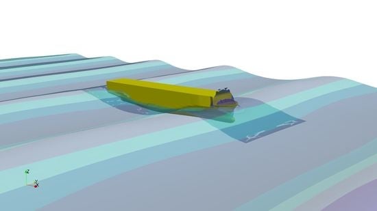
Article

Comparative Study of Potential Flow and CFD in the Assessment of Seakeeping and Added Resistance of Ships

by
Ivan Sulovsky
1,*,
Guillaume de Hauteclocque
2,
Marilena Greco
3,4 and
Jasna Prpić-Oršić
1
1
Faculty of Engineering, University of Rijeka, Vukovarska 58, 51000 Rijeka, Croatia
2
Research Department, Marine & Offshore Division, 92800 Paris, France
3
Department of Marine Technology, Norwegian University of Science and Technology, 7050 Trondheim, Norway
4
CNR-INM, Institute of Marine Engineering, 00128 Rome, Italy
*
Author to whom correspondence should be addressed.
J. Mar. Sci. Eng. 2023, 11(3), 641; https://doi.org/10.3390/jmse11030641
Submission received: 21 February 2023 / Revised: 14 March 2023 / Accepted: 15 March 2023 / Published: 17 March 2023
(This article belongs to the Special Issue CFD Applications in Ship and Offshore Hydrodynamics)

Abstract

:
The need for maritime freight transport of various goods has never been greater. Consequently, ships are designed with ever-increasing dimensions, with the emphasis, of course, on length. One of the many challenges in the design of large ships is the prediction of their behavior in waves, i.e., motions, and consequently, added resistance. In this paper, a comparative study of two numerical tools for estimating ship motions and added resistance is presented. The first tool is the well-established DNV’s commercial seakeeping code Wasim, a weakly nonlinear potential flow (PF) solver based on a Rankine panel method. The other is the increasingly recognized open-source Computational Fluid Dynamic (CFD) toolkit OpenFOAM®, a viscous flow solver with a turbulence model; it is based on the finite volume method (FVM) combined with a volume-of-fluid (VOF) technique for sea-surface evolution. The study is carried out for two ship seakeeping cases in head-sea regular waves, respectively, without and with ship forward speed. The first case refers to a 6750 TEU containership scale model developed at the LHEEA laboratory in Nantes for a benchmark study, providing experimental data for all test cases. Pitch and heave response is calculated and compared with the experimental values. The second case refers to a KRISO container ship, an extensively researched hull model in ship hydrodynamics. In addition to the pitch and heave, added resistance is also calculated and compared with the experimental values. Hence, it provides a comprehensive basis for a comparative analysis between the selected solvers. The results are systematically analyzed and discussed in detail. For both cases, deterioration of the PF solution with increasing wave steepness is observed, thus suggesting limitations in the modeled nonlinear effects as a possible reason. The accuracy of the CFD solver greatly depends on the spatial discretization characteristics, thus suggesting the need for grid independence studies, as such tools are crucial for accurate results of the examined wave–body interaction scenarios.

Graphical Abstract

1. Introduction

In ocean engineering, predicting seakeeping responses in high-amplitude waves is of high value for various design aspects. Avoiding unwanted motions and accelerations can result in significant savings in fuel, equipment damage, general comfort, etc. From a structural safety viewpoint, navigating in an extreme sea state can cause large vertical bending moments amidships for slender, long, ocean-going vessels. As for seakeeping performance, relevant wave-induced motions and scattering effects, for instance, lead to added resistance contributions. The adequate prediction of added resistance in waves enables for interventions in terms of reducing fuel consumption in the early stage of ship design. Today, the most common methods for the numerical estimation of ship motions and added resistance involve potential-flow three-dimensional (3D) or strip-theory codes within a perturbation approach. However, these methods cannot properly capture all nonlinear effects relevant in rather steep waves [1]. The use of Reynolds-averaged Navier–Stokes (RANS) equations coupled with rigid body motion solvers can overcome the limits of the methods above, as it allows nonlinear effects associated with both potential- and real-flow effects to be accounted for. Numerical investigations of the seakeeping characteristics of floating objects in large waves with fully viscous CFD within a finite volume framework are still limited [2,3,4,5]; this is reasonably due to the high computational cost on one side and reliability issues on the other. A distinguishing challenge when dealing with high-amplitude body motions within CFD is the generation and application of an appropriate dynamic mesh strategy. This is especially crucial when targeting second- and higher order wave-induced loads, as they are smaller than linear loads and therefore more sensitive to numerical discretization strategies; one must note that they also represent a challenge for experimental studies—in fact, those in this context are somewhat limited. Gao et al. [6] compared and validated several dynamic mesh strategies, including the scenario of ship capsizing in regular beam-sea waves. For large amplitudes of motion, overset (chimera) grids seem to be the most appropriate. The concept behind the overset is to combine any number of independent computational domains with the motion pre-specified or computed for each individual domain. In computational marine hydrodynamics, this concept is a useful tool for evaluating, e.g., rudder–hull–propeller interaction, zig-zag maneuvers, or any other complex hydrodynamic scenarios involving large body motions. For instance, Galbraith and Boulogouris [7] simulated roll motions of a tumblehome hull undergoing a parametric resonance, which can result in very high roll angles depending on the hull geometry, level of damping, ship heave and pitch motions, and incident-wave features. The overset mesh technique has proved its robustness in numerous seakeeping numerical investigations [8] in which large amplitude motions are not restricted, as in more conventional morphing meshes. The price to pay for such a technique is the increased computational cost. Apart from the dynamic mesh strategy, simulating free-surface waves is by no means trivial in computational fluid dynamics. Challenges encountered in creating a numerical wave tank include a loss of wave height in the case of an insufficiently fine mesh (dissipative errors), inaccuracies in the wave-propagation mechanisms (dispersive errors), unwanted wave reflections at the outlet boundary, etc. Jacobsen et al. [9] provide substantial documentation in this field in the context of a publicly available toolbox for free surface wave generation and absorption in OpenFOAM® [10]. Furthermore, appropriate turbulence modeling needs to be addressed for wave generation if turbulence is expected to matter for the examined wave–body interaction problems. The most used turbulence models in marine applications are k-ε and k-ω SST [11]. However, with both models, numerical instability occurs with free-surface waves through the non-physical build-up of turbulent viscosity, thus creating high and unrealistic damping of the waves [12]. The overall influence of turbulence modeling in seakeeping simulations within CFD is speculative, since the pressure and velocity gradients in the flow are very high near the hull, making single-phase turbulence models rogue [13]. Moctar et al. [14] even suggest omitting fine boundary layers along the hull if viscous effects are to be neglected. However, further investigations are needed in this area. In the present paper, a seakeeping response assessment, with added resistance included, is performed for two ships for which model-test results are available. The first case concerns a 6750 TEU containership model with zero speed in head-sea regular waves, in which pitch and heave responses are analyzed. Preliminarily, a thorough investigation was performed regarding the mesh quality within CFD for the propagation of waves with a two-dimensional (2D) numerical wave tank; an assessment was performed for five different wave heights and keeping the wavelength fixed and equal to the ship length. The second case refers to the KRISO containership model advancing in head-sea waves. Both cases are investigated with two numerical tools for marine hydrodynamics: (A) the commercial code Wasim from DNV classification society, based on potential flow theory, i.e., a Rankine panel method, and including second-order nonlinear effects within a perturbation approach, hereafter briefly indicated as PF; and (B) the open source CFD toolkit OpenFOAM® based on the co-located finite volume method (FVM), hereafter briefly indicated as CFD. This comprehensive study provides additional insights into the performance of these two hydrodynamic tools for estimating ship response and added resistance in waves, their shortcomings, and their advantages. The rest of this paper is structured as follows. In Section 2, the experimental setups and test matrices for the two studied cases are outlined. The two selected numerical tools are described in Section 3. In the same section, the incident-wave parameters for the first experimental case are used to carry out a systematic analysis to identify the grid size and time-step needed to limit the numerical errors of the CFD solver. The results from all seakeeping simulations are documented in Section 4, together with their comparison against the corresponding physical data, and the main conclusions are drawn in Section 5.

2. Benchmark Tests

2.1. 6750 TEU Containership

The experimental data for the first case presented in this paper originate from [15], which addresses the uncertainties of different numerical approaches for the evaluation of extreme vertical bending moments in ship structures. The experiment was conducted in the Hydrodynamic and Ocean Engineering Tank in The Research Laboratory in Hydrodynamics, Energy and Atmospheric Environment (LHEEA) in Nantes, France. The tank is 50 m long, 30 m wide, and with a water depth of 5 m. The ship model, a 6750 TEU containership at 1:65 scale with main dimensions given in Table 1, and the body plan and model are shown in Figure 1a,b, respectively. Figure 1b shows the same hull shape as in [15] but corresponds exactly to [16].
The prescribed regular head-sea waves are given in Table 2. With the intention of limiting excessive surge of the ship, soft mooring is imposed with a resulting surge natural period of 11.8 s. This is achieved using four springs, k1, k2, k3 and, k4, all of which have the same stiffness of 56 N/m. The angle α between pairs of springs at the bow and stern is equal to 45°. The mooring arrangement is shown in Figure 2.

2.2. KRISO Container Ship

The KRISO container ship (KCS) model [17] was conceived as a design of a modern container ship with a bulbous bow and tested in a towing tank by the Korea Research Institute for Ships and Ocean Engineering [18,19] to provide benchmark data for validation purposes. The prescribed regular head-sea waves are given in Table 3, while the main ship dimensions are documented in Table 4, with the body plan depicted in Figure 3. The entire set of experimental data is publicly available at [20]. No full-scale ship exists with this exact geometry. Note that the wetted surface S includes the wetted surface area of the rudder as the only appendage included in the experiments.

3. Numerical Methods

Details of the numerical features specific to PF and CFD are outlined in this section. The numerical schemes that were used are briefly described, followed by computational grid properties for each case. Regarding CFD, OpenFOAM® is an open-source type of software; hence, detailed information about the numerical set-up ensures the reproducibility of this study. Turbulence modeling is summarized for such applications with appropriate boundary conditions used.

3.1. Numerical Schemes—Potential Flow

The potential flow solver used in this study is the DNV’s commercial code Wasim. It is a 3D panel method, distributing Rankine sources on the free surface as well as the body, and solves equations of motion in the time domain. It can be applied for ships of arbitrary speeds and shapes with linear or nonlinear motion and wave load analysis [21]. In PF theory, idealization is introduced as fluid being inviscid, irrotational and incompressible. Such idealizations significantly reduce the computational costs in seakeeping problems and are, therefore, one of the main tools for such tasks in marine applications. In the basic Wasim implementation, the restoring and Froude–Krylov pressures are computed at the instantaneous wetted body surface, which is defined by the rigid body motions and the incident waves; the radiation/diffraction effects are estimated within the linear theory, with the corresponding pressures integrated along the mean wetted surface, with the quadratic term in the Bernoulli equation included. The nonlinearities of the incident waves can be modeled using Stokes wave theory or Stream function; other nonlinear terms may be included in the free-surface elevation of the wave–body interaction problem. For the seakeeping of advancing vessels, both Neumann–Kelvin and double-body linearization can be used. In both cases examined in the paper, the Neumann–Kelvin linearization method is applied. The influence of the double-body linearization method was not investigated due to the slenderness of involved ship hulls. Comparative studies of these two methods are extensively documented in [22,23]. Added resistance in waves is calculated as a result of direct pressure integration in time. Temporal discretization within Wasim offers first- and second-order schemes, the choice of which depends on the so-called grid Froude number Fh, Equation (1).
F h = U g h x
where U stands for ship speed, g is the gravitational acceleration and hx represents the smallest panel length in the longitudinal ship direction. For more detailed information on this, the reader is referred to [24]. Computational meshes are shown in Figure 4 for the 6750 TEU containership and KRISO containership, respectively. HydroMesh utility within Wasim offers fast, automatic meshing of both the hull and free surface.

3.2. Numerical Schemes—CFD

The CFD simulations in this paper are established using OpenFOAM®, in which the co-located finite volume method is applied to solve fluid mechanics equations. Fluid flow is governed by Navier–Stokes (NS) equations for incompressible flows, the continuity Equation (2) and momentum Equation (3):
· u = 0
u t + ( u · ) u ν 2 u = 1 ρ p + g
where u is the local fluid velocity. The LHS of the NS equation contains the total derivative, i.e., the change of velocity in time, convective term and viscous term, respectively. p is the pressure gradient, g is the gravitational acceleration and ν stands for effective kinematic viscosity. For solving these equations, the interFoam solver is engaged for two incompressible, isothermal immiscible fluids (water and air). The air–water interface is modeled using the Volume of Fluid method (VOF), in which indicator function α is introduced into the partial differential equations. The α function represents a scalar field that enters the NS equations through density ρ and effective kinematic viscosity ν , as depicted in Equations (4) and (5), respectively.
ρ = ( 1 α ) ρ a i r + α ρ w a t e r
ν = ( 1 α ) ν a i r + α ν w a t e r
The MULES algorithm [25] is used for the bounding of α with the conservation equation. For temporal discretization, the Crank–Nicolson scheme is applied with a coefficient of 0.9, which is a second-order time scheme suitable for such transient problems. The first-order scheme is skipped since it is prone to excessive numerical diffusion. Convective terms are solved with the linear scheme that limits towards upwind, i.e., the direction of the flow in regions of strong gradients. Other gradient terms, i.e., diffusive terms, are discretized with Gaussian linear interpolation. The pressure–velocity coupling is resolved using the PIMPLE algorithm with four iterations per time-step in total, two for pressure residual and two for a momentum matrix. For the hydro-mechanical coupling of the rigid body motions of the ship and fluid flow, the six degrees of freedom solver is employed with imposed restrictions for sway, yaw, and roll.

3.2.1. Two-Dimensional Numerical Wave Tank

To ensure that the selected CFD solver can adequately generate and simulate the incident regular waves required for the seakeeping analysis, a 2D numerical wave tank with no body is preliminarily examined. The length of the tank is obtained from [26] and the height from [27]. The computational grid is created using blockMesh and topoSet tools within OpenFOAM®, setting the breadth (i.e., the domain size normal to the flow motion) equal to one-cell size and using proper boundary conditions to ensure two-dimensional wave conditions. Due to the reduced number of cells, this procedure provides results within minutes. Relaxation zones [9] are employed to tackle the problem of wave reflections at the outlet and artificial velocities at the inlet during wave build-up. The length of the relaxation zones is determined as a function of the wavelength λ of the targeted generated waves, as proposed in [26]. The second-order Stokes wave model is used as input for the wave kinematics. Five different wave heights are tested at a given λ, corresponding to the experimental waves listed in Table 1. To measure the simulated wave height, a virtual wave gauge is placed at a longitudinal distance from the wave-generation side that corresponds to the forward perpendicular of the ship model (when the seakeeping simulations are performed); this position is hereafter indicated as LPP. The main individual zones of the numerical wave tank are depicted in Figure 5.
The main objective of this wave study is to determine the spatial and temporal discretization suitable for accurate and efficient simulations of wave propagation, given the selected wave parameters. Variables to which wave propagation is sensitive include: the number of cells per wave height, number of cells per wave length, and the time-step of the simulation. Since all wave conditions have the same wave length, only the variation of the cells per wave height is investigated. In terms of numerical stability, the time-step ∆t should be chosen so that the Courant number Co, Equation (6):
C o = v i Δ t Δ x i < 1
where vi is the local fluid velocity and ∆xi is the local cell size in the x direction. Here, to reduce the numerical dissipation at the free surface, the Courant number is kept below 0.2. As for the number of cells per wave height N, three grid densities are examined while keeping the Courant number at the free surface equal to 0.2, so the time-step is modified consistently. Figure 2 confirms the significant influence of N for the development of the free surface wave prescribed for case 3 (see parameters in Table 1) in terms of the wave elevation at the selected virtual gauge. Time histories appear very coarse due to the plotting time interval set to 0.2 s. Asymmetry between wave trough and crest also appears, which happens due to nonlinearities in free surface flows for the examined wave parameters. Turbulence modeling was not employed, since turbulence effects are expected to play a negligible role for these scenarios of wave propagation, as we have in mind sufficiently long gravity-driven waves. Nevertheless, it was also investigated, as seen in Figure 6. After 17 s of simulation time, the damping of the wave height becomes more exaggerated for the targeted wave height of 0.23 m.
The issue of the artificial damping of the wave height relates to the instability of the turbulence model and is expected to be much more relevant for simulations of longer duration and irregular waves. Therefore, one needs to take proper care of the turbulence modeling in such conditions. One of the possible solutions within OpenFOAM is to implement one of the stabilized turbulence models from Larsen and Fuhrman [12]. In this study, stabilized turbulence models were not implemented.
Following this parametrical study, eight cells per wave height were confirmed to be sufficient for wave propagation and are adopted as a minimum value of cell number per wave height further in the paper. In the horizontal wave-propagation direction, the guideline from Moctar et al. [14] for the coarsest discretization of at least 30 cells per wavelength is far exceeded. For the quantification of wave-height propagation error in a wave tank, the procedure from [28] is adopted. The maximum, ηmax, and minimum, ηmin, values of the wave elevation are estimated at the position of x = LPP in a time interval nT, equal to n = 7 wave periods T, when nearly steady-state conditions are established. This is used to estimate the wave height in each oscillation period kT, with 1 k n , as shown in Equation (7). The mean value of the wave height is calculated according to Equation (8), and the percentage error is estimated using Equation (9), where H is the targeted wave height given in Table 1 for each wave case. Corresponding results for N = 8 are given in Table 5. while the influence of N on the wave amplitude error is documented in Figure 7 for case 3.
H L P P , k = [ | η m i n | + η m a x ] L P P , k  
H L P P , n ¯ = k = 1 k = n H L P P , k n
e = H L P P , n ¯ H · 100
Regarding the possible errors associated with the temporal discretization, i.e., time-step, three values are examined with respect to the wave period: T/200, T/400, and T/600. Since the benchmark cases involve almost the same wave period, the temporal discretization analysis is only examined for case 3. The procedure is the same as for spatial discretization, i.e., it uses the error in the wave height at x = LPP. The results are documented in Table 6.
Sensitivity due to time-step size in these ranges is negligible, while the number of cells per wave height has much greater influence over wave propagation within the finite volume framework. Considering the presented results of this wave study, values of eight cells per wave height and a time-step of T/400 are obtained as numerical guidelines for the modeling seakeeping response in OpenFOAM®. A computational grid with refinement zones within free surface for case 5 is shown in Figure 8.
Case 5 corresponds to the steepest incident-wave scenario examined. In this case, wave breaking is noticed with features similar to spilling breakers, as documented in Figure 9. The breaking itself is purely numerical, since the wave parameters are far from the wave breaking criteria of H/λ > 0.142.

3.2.2. 6750 TEU Containership: Computational Grid, Linear Solvers and Boundary Conditions

Regarding the PF setup, details are outlined in Section 3.1. Setting up the computational grid for CFD is usually followed by discretizing the hull model into the appropriate format beforehand. The STL (stereolithography) format of the file is chosen, in which the hull surface geometry is split into a series of linked triangles that encloses a watertight volume object. For the case of the 6750 TEU containership, container stackings are also included but with a simplified geometry in order to reduce unwanted sharp edges. Green water protection is also accounted for at the forecastle, which will likely decrease the overflow volume of the water fraction on the deck. The STL geometry of the hull model is shown in Figure 10. No appendages are included in both experimental and numerical models. Hull models for both cases are available online as a Supplementary Material for reproduction of the results.
Volume mesh is constructed with the blockMesh tool and consists of regular polyhedron cells with an aspect ratio of approximately 1, since it is an intrinsic requirement for overset interpolation. The length of the domain is set to be 5.5λ, while breadth and height are 2λ in total, with λ being the incident wavelength. The relaxation zones are the same as described in Section 3.2.1. Imposing relaxation zones on the sidewalls is skipped because the simulation duration is predicted not to be long enough to capture reflections from the diffracted waves of the ship motions. Since the overset mesh technique is adopted for this case, two separate meshes must be constructed and then coupled through interpolations and information exchange. The SnappyHexMesh and topoSet tools are used for refinements in the relevant regions. The global arrangement of the computational domain is depicted in Figure 11 with the nomenclature of boundary faces. The background mesh is colored in blue, while the overset mesh is in yellow.
The origin of the coordinate system is located at the intersection between the aft perpendicular of the ship and the free surface for calm water conditions. Particular attention is dedicated to the overlapping region of the overset and background meshes. The connection between these regions is obtained through numerical interpolation, in which the user can choose several numerical schemes for interpolation. In this work, the inverse-distance weighted interpolation method is selected. Detailed numerics and performances of overset interpolation strategies within OpenFOAM® are covered in [29]. The refined mesh in the vicinity of the hull can be seen in Figure 12.
For the closure of NS equations, a realizable k-ε turbulence model is applied. Boundary conditions specific for wave applications are set for velocity and phase fraction field at the inlet and outlet. The boundary condition for the pressure is the same at the inlet and outlet to correct the pressure gradient accordingly, so that the flux on the boundary is specified by the velocity boundary condition. The slip boundary condition is imposed at both sidewalls, while wall functions are applied to the hull surface. Regarding the mesh size, approximately 4 to 5 million cells are generated for computation for every benchmark case. The leading concept for mesh generation is the minimum of eight cells per wave height, as shown in Section 3.2.1. The entire computational domain is shown in Figure 13, where intense refinements can be seen in the free-surface region, and in the vicinity of the hull, where high gradients of velocities and pressure are expected.
The time-step for every case is set to 0.005 s, ensuring that the local Courant number is less than 0.2 in the free surface area. All calculations are made on an HPC cluster, most often on eight nodes with 24 cores each, making 192 physical cores available for computation. For the decomposition method, the scotch method is used, where the same number of computational cells are assigned to each physical core. Regarding linear solvers, for solving large sparse matrices that are yielded from a FV mesh, a conjugate gradient (CG) method is chosen with a Cholesky preconditioner. Residual tolerance is set to 1−8. Velocity components and turbulence terms are solved using a smooth solver, i.e., Gauss–Seidel smoother with a residual tolerance of 1−8.

3.2.3. KRISO Containership: Computational Grid, Linear Solvers and Boundary Conditions

Numerical details for the PF solution are listed in Section 3.1. For CFD, the overset approach is skipped, presuming that, due to the lower wave heights, the deforming grids would be sufficient. Moreover, wave damping along the tank differs from the first case. The damping itself is modeled as an explicit damping force applied to the momentum equation proportional to the momentum of the flow in the direction of gravity. For detailed information on this, the reader is referred to [30]. As the first condition of the experimental study of the KRISO case includes calm water resistance with free sinkage and trim, computational grids are adequately built for the calm water and waves scenarios. The grid for the calm water condition is outlined first. For this case, the computational domain is modeled for only half of the ship, thus imposing a symmetric boundary condition, which coincides with the vertical symmetry plane of the center line of the ship. The domain extents are according to ITTC standards [31]. The boundary faces are of the same topology as in Figure 8, except for the omitted overset region. Numerical schemes are the same as those depicted in Section 3.2, except for the calm water condition, where an implicit Euler scheme is chosen for temporal derivatives. The thickness of the boundary layer in the grid is equal to 18.5 mm with an expansion ratio of 1.5, which ensures the average value of y+ on the hull of approximately 40. These values are determined based on the author’s previous experience with such calculations. The K-ω SST turbulence model is applied for calm water conditions, where turbulent kinetic energy k for the far-field boundary conditions is specified as:
k = 3 2 ( U f s I ) 2
Ufs stands for free stream velocity and I is the turbulence intensity, which is assumed at 3%. The specific dissipation rate is defined following the guideline from Eça and Hoekstra [32]:
ω = 10 U L P P
where LPP is the length between the ship perpendiculars. The realizable k-ε turbulence model is chosen for wave conditions, since the dissipation and dispersion errors in the wave propagation are sufficiently small for short-duration simulations including regular waves if compared to the k-ω SST model. It is assumed that using different turbulent models will not affect any of the physical quantities being investigated in the paper, i.e., rigid body motions and second-order longitudinal force (added resistance in waves). Computational grids are shown in Figure 14 and Figure 15 for calm water and wave conditions, respectively. For the wave application, the mesh in the free-surface zone is refined in horizontal and vertical directions, thus drastically increasing the number of cells. As for the linear solvers, for asymmetrical matrices (turbulence terms, velocity components and α), the setup is the same as depicted in Section 3.2, while for symmetrical matrices, i.e., pressure equation, a Generalized Geometric–Algebraic multigrid solver (GAMG) is chosen with a Gauss–Seidel smoother with a residual tolerance of 1−7. Computational grids for the KRISO containership are outlined in Figure 14 and Figure 15.

4. Results and Discussion

The results of the simulations for the examined ship seakeeping cases are outlined in this section. Post-processing of the CFD results is also carried out using open-source tools, namely paraView® for visualization and python Spyder for Fourier transformations and plots.

4.1. Heave and Pitch Response of the 6750 TEU Containership

The heave and pitch response for the 6750 TEU containership are examined in this section. Heave amplitude z is made nondimensional by the wave amplitude ς, while the pitch amplitude θ is normalized with wave number k multiplied by wave amplitude. The heave results from PF and CFD are plotted in Figure 16, showing a drastically different trend of the heave from the two codes. The CFD results indicate a minimum with the unusually low response of the heave for H = 0.17 m, while the PF results predict a monotonous decrease with the wave height. For the two largest wave heights, the heave response from Wasim is significantly lower than from the CFD. Experimental data for heave motion are not shown since they are omitted even in the benchmark study due to insignificantly low amplitudes. However, the results are shown in Figure 16. Figure 17 documents the nondimensional amplitude of pitch for all results. Regarding CFD, overprediction of the pitch motion appears for H = 0.17 m, while the experimental response is underestimated for the lowest wave condition. The solution from the potential-flow solver shows a significant reduction in accuracy for almost all wave conditions, except for the lowest wave case.
The quantitative difference of the nondimensional pitch amplitudes from the experiment is listed in Table 7, while it is graphically shown on a bar diagram in Figure 18.
Photos from the experiment compared with snapshots from OpenFOAM are shown in Figure 19 for case 5. As can be seen, both results indicate the occurrence of substantial water on deck. Therefore, pitch motion is influenced by this effect, which can be seen in Figure 20 with magnification over the area of the bow emerging from the water. Clearly, CFD can capture some of these effects; however, for a more accurate solution, the grid density above the freeboard, along with the appropriate multiphase solver that reduces smearing of the free surface, should be considered. One of these solvers is implemented in OpenFOAM, which is based on the more accurate reconstruction of the face fluxes for the cells containing the interface [33].

4.2. Calm Water Resistance with Free Sinkage and Trim of KRISO Containership

The results of calm water resistance with the free sinkage and trim of the KRISO containership are outlined in this section. In Figure 21, the sum of pressure and viscous components is shown as a blue line, i.e., total force and experimental data (EFD) in red. Furthermore, the isolated viscous component is compared with the ITTC 1957 correlation line in Equation (13). The values of the forces are presented in a nondimensional manner with resistance coefficient CT, Equation (12), in which RT stands for total resistance, r being the fluid density, U the speed of the ship and S0 the wetted surface area at rest:
C T = R T 0.5 ρ U 2 S 0
C F = 0.075 ( l o g 10 R e 2 ) 2
Re stands for Reynolds number and is equal to 1047 × 107 for model scale.
It is important to point out that the ITTC empirical formula is for an equivalent smooth plate in turbulent flow conditions. It is reasonable for the ship hull to have a larger frictional coefficient due to its 3D features. Their comparison would indicate a small form factor of about 0.075, which is consistent with a slender ship hull. The numerical results from Figure 21 are summarized in Table 8, where CT is the resistance coefficient, θt is the trim angle in degrees, and zs is the sinkage in meters, normalized with LPP.
Aside from sinkage, the results agree well with the experiment following the assumption that the coarse mesh adopted for this study yields a high discrepancy of the sinkage.

4.3. Heave, Pitch and Added Resistance of KRISO Containership

The results of the heave, pitch and added resistance of the KRISO containership are outlined in this section. They are presented following the convention of the experiment; raw signals are processed via Fourier transforms to evaluate the n-th harmonic amplitude for one encounter period Te, see Figure 22, Figure 23, Figure 24, Figure 25 and Figure 26. Furthermore, transfer functions are graphically shown to satisfy the more conventional presentation. Regarding the fact that the PF tool, being a seakeeping solver, does not provide calm water resistance, the calm water component of the total resistance coefficient in Equation (12) for Wasim is taken from CFD results. Guidelines for the Fourier transform of the signals are given in [24].
The transfer functions of heave and pitch along with the total resistance coefficient are plotted in Figure 27, Figure 28 and Figure 29, in which the transfer function is estimated as a sum of the motion amplitude in a stable range of the simulations. Discrepancies with the experimental data are summarized in Table 9, Table 10 and Table 11 with associated bar diagrams in Figure 30, Figure 31 and Figure 32.
Snapshots from the simulations with representative contours of incident waves are shown in Figure 33.

4.4. Discussion

A discussion of the results is outlined in this section for the 6750 TEU containership and KRISO containership, respectively. Regarding the first case, an experiment is chosen in which only the wave height varies, while the wavelength remains constant. It provides an opportunity to investigate wave response with regards to wave steepness for a zero-speed case. Such operating conditions are relevant, for example, FPSO vessels. First, the heave response is analyzed from both codes. The results indicate significant differences between the two tools, with a trend of lower values from the PF code compared to CFD. That is, however, not only the case for the second wave condition (H = 0.17 m). Looking at the pitch response for which the experimental data are known, CFD performs better as the wave height increases. For smaller wave heights (H < 0.20 m), PF gives more accurate results. It can be assumed that for smaller rigid body responses in CFD, more computational cells than eight are needed in the free surface area. Moreover, it is possible that overset interpolation errors are magnified for smaller amplitudes; hence, an appropriate interpolation strategy should be chosen, most preferably the least squares method. Deforming grids should also be considered if the amplitudes are such that the numerical penalties would not appear due to morphing. Furthermore, analyzing the wave conditions for the 6750 TEU containership, at full scale, the biggest incident wave height would be equal to 29.2 m, which represents very extreme but also improbable conditions at sea. These extreme conditions provide a valuable experimental dataset for testing and comparing different seakeeping codes in harsh environments. The second case studied in this paper, the KRISO containership, is unlike the previous one, which is subjected to milder wave conditions. In this case, a model scale containership is subjected to head waves only while towed at a constant forward speed. The results of this case from CFD indicate that all hydrodynamic parameters of interest are prone to under or overprediction for small wave heights independently of the accurate incident wave, as stated in the 2D numerical wave tank study. As seen in Figure 24, Figure 25 and Figure 26, the difference from the experimental value becomes smaller as the wave height increases. The reason for this could be that for relatively smaller incident wave heights, the number of cells per wave height should be greater than eight, enabling the solver to capture small rigid body amplitudes and pressure changes from cell to cell. The analysis of the transfer functions of Wasim shows that there is a lack of accuracy, and the motion is mostly underestimated. Pitch response has the biggest differences from the experiment, which can be attributed to the lack of viscous damping term; however, further investigation is needed. Finally, added resistance shows a similar trend for both Wasim and OpenFOAM®. In Figure 22c, no report is made for the added resistance from Wasim, since the resonant behavior in the measurements was reported. Interestingly, resonance is also captured in CFD with two force peaks over one encounter period. Observing the total resistance coefficient, i.e., added resistance from Wasim, higher harmonics are not captured.

5. Conclusions

The main objective of this paper is to present a comparison of two hydrodynamic tools for the assessment of seakeeping characteristics and added resistance of seagoing vessels. The first is based on potential flow theory and originates from the classification society DNV—Wasim. The second is an open-source toolbox for computational fluid dynamics—OpenFOAM®. In the study, two different cases are investigated, the first being a 6750 TEU containership scale model without forward speed, subjected to steep head waves. Heave and pitch response are analyzed, while only the latter is compared to the experiment. Regarding heave motion, a different trend of amplitudes is revealed from Wasim and OpenFOAM®. For Wasim, the amplitude is significantly smaller for the bigger wave heights compared to the CFD solver. For the pitch motion, the underestimation of the motion by the potential flow is clear. CFD shows better agreement with the experimental values, leading to the conclusion that for increasingly steep waves, heave can be underestimated with the potential flow tools with Wasim features. The use of CFD can also ensure better accuracy, but grid independence studies should be carried out. It is particularly evident in the second case of this work: a KRISO containership subjected to head waves with forward towing speed. Rigid body motions, i.e., heave and pitch, agree quite well for CFD, while the solution from PF differs for all cases. For the viscous flow method, differences in the experiment for lower wave heights are attributed to an insufficient number of computational cells per wave height, regardless of the accurate incident wave. Regarding second-order effects such as added resistance, CFD also shows better agreement. From a practical point of view, the constant towing speed and the restricted surge motion strongly affect the forces acting on the hull. Hence, the solution is not entirely suitable for estimating the sea margin for a real ocean-going ship. Clearly, the CFD solver will yield a more accurate solution, in which careful modeling of the surge response should be taken care of. Comparing the solutions for the potential flow in both cases, it is clear that the percentage difference is of a very different order of magnitude. This indicates that the forward speed effect in the PF tool should be studied in detail using the double-body linearization method, free-surface nonlinearities, etc. This is the subject of further planned work in future studies. Investigations of seakeeping performance with stabilized turbulence models within CFD are scarce, making it a fruitful area for further research. As a general guideline for the choice of a potential flow tool, or a fully viscous CFD for seakeeping or added resistance derived from this work: If a very sharp accuracy of the solution is required, i.e., a difference of less than 3 or 5%, then a fully viscous CFD is an option, considering the expected high computational cost. If such high accuracy is not of utmost importance, then a potential flow tool with features such as those analyzed here is the right choice, taking care that the vessel is in a linear region of motion, i.e., the height of the incoming waves is relatively low with respect to their characteristic length.

Supplementary Materials

The STL hull models for reproduction can be downloaded at: https://www.mdpi.com/article/10.3390/jmse11030641/s1, STL mesh of KRISO containership: KCS.stl., STL mesh of 6750 TEU containership: 6750 TEU containership.stl.

Author Contributions

Conceptualization, I.S., M.G. and J.P.-O.; Investigation, I.S.; Methodology, I.S., M.G. and J.P.-O.; Project administration, J.P.-O.; Resources, G.d.H.; Software, I.S. and J.P.-O.; Supervision, M.G. and J.P.-O.; Writing—review and editing, I.S. All authors have read and agreed to the published version of the manuscript.

Funding

This work was supported by the Croatian Science Foundation under the project IP-2018-01-3739.

Institutional Review Board Statement

Not applicable.

Data Availability Statement

All data (hull surface geometry, wave conditions, etc.) are available online.

Acknowledgments

The first author is grateful to NTNU (Norwegian University of Science and Technology) for hosting him, as a result of which this paper was produced. The first author also wishes to thank Andro Bakica for his initial help and guidance with OpenFOAM.

Conflicts of Interest

The authors declare no conflict of interest.

References

  1. Joakim Tveiten Vigsnes Seakeeping Analysis Comparison between Viscous and Inviscid CFD. Master Thesis. Available online: https://ntnuopen.ntnu.no/ntnu-xmlui/handle/11250/2566949 (accessed on 10 January 2023).
  2. Katsidoniotaki, E.; Göteman, M. Numerical modeling of extreme wave interaction with point-absorber using OpenFOAM. Ocean Eng. 2022, 245, 110268. [Google Scholar] [CrossRef]
  3. Kim, S.-G.P. CFD as a seakeeping tool for ship design. Int. J. Nav. Archit. Ocean Eng. 2011, 3, 65–71. [Google Scholar] [CrossRef] [Green Version]
  4. Dorozhko, V.M.; Bugaev, V.G.; Kitaev, M.V. CFD Simulation of an Extreme Wave Impact on a Ship. In Proceedings of the Twenty-fifth International Ocean and Polar Engineering Conference, Kona, HI, USA, 21–26 June 2015. [Google Scholar] [CrossRef]
  5. Bi, X.; Zhuang, J.; Su, Y. Seakeeping Analysis of Planing Craft under Large Wave Height. Water 2020, 12, 1020. [Google Scholar] [CrossRef] [Green Version]
  6. Gao, Z.; Wang, Y.; Su, Y.; Chen, L. Validation of a combined dynamic mesh strategy for the simulation of body’s large amplitude motion in wave. Ocean Eng. 2019, 187, 106169. [Google Scholar] [CrossRef]
  7. Galbraith, A.; Boulougouris, E. Parametric Rolling of the Tumblehome hull using CFD. In Proceedings of the 12th International Conference on the Stability of Ships and Ocean Vehicles, Scotland, UK, 14–19 June 2015. [Google Scholar]
  8. Shen, Z.; Wan, D.; Carrica, P.M. Dynamic overset grids in OpenFOAM with application to KCS self-propulsion and maneuvering. Ocean Eng. 2015, 108, 287–306. [Google Scholar] [CrossRef]
  9. Jacobsen, N.G.; Fuhrman, D.R.; Fredsøe, J. A wave generation toolbox for the open-source CFD library: OpenFoam®: Wave Generation Toolbox. Int. J. Numer. Methods Fluids 2012, 70, 1073–1088. [Google Scholar] [CrossRef]
  10. Weller, H.G.; Tabor, G.; Jasak, H.; Fureby, C. A tensorial approach to computational continuum mechanics using object-oriented techniques. Comput. Phys. 1998, 12, 620. [Google Scholar] [CrossRef]
  11. Pena, B.; Huang, L. A review on the turbulence modelling strategy for ship hydrodynamic simulations. Ocean Eng. 2021, 241, 110082. [Google Scholar] [CrossRef]
  12. Larsen, B.E.; Fuhrman, D.R. On the over-production of turbulence beneath surface waves in Reynolds-averaged Navier–Stokes models. J. Fluid Mech. 2018, 853, 419–460. [Google Scholar] [CrossRef] [Green Version]
  13. Gatin, I.; Vukčević, V.; Jasak, H.; Seo, J.; Rhee, S.H. CFD verification and validation of green sea loads. Ocean Eng. 2018, 148, 500–515. [Google Scholar] [CrossRef]
  14. el Moctar, B.O.; Schellin, T.E.; Söding, H. Numerical Methods for Seakeeping Problems; Springer: Cham, Switzerland, 2021; ISBN 978-3-030-62561-0. [Google Scholar]
  15. Bouscasse, B.; Merrien, A.; Horel, B.; Hauteclocque, G.D. Experimental analysis of wave-induced vertical bending moment in steep regular waves. J. Fluids Struct. 2022, 1111, 103547. [Google Scholar] [CrossRef]
  16. Kim, Y.; Kim, J.-H. Benchmark study on motions and loads of a 6750-TEU containership. Ocean Eng. 2016, 119, 262–273. [Google Scholar] [CrossRef] [Green Version]
  17. Kim, W.J.; Van, S.H.; Kim, D.H. Measurement of flows around modern commercial ship models. Exp. Fluids 2001, 31, 567–578. [Google Scholar] [CrossRef]
  18. Larsson, L.; Stern, F.; Visonneau, M. Numerical Ship Hydrodynamics: An Assessment of the Gothenburg 2010 Workshop; Springer: Dordrecht, The Netherlands, 2014; ISBN 978-94-007-7189-5. [Google Scholar]
  19. Simonsen, C.D.; Otzen, J.F.; Joncquez, S.; Stern, F. EFD and CFD for KCS heaving and pitching in regular head waves. J. Mar. Sci. Technol. 2013, 18, 435–459. [Google Scholar] [CrossRef]
  20. Tokyo 2015: A Workshop on CFD in Ship Hydrodynamics. Available online: https://www.t2015.nmri.go.jp/Instructions_KCS/Case_2.10/Case_2-10.html (accessed on 10 January 2023).
  21. Heo, J.; Park, D.; Berg-Jensen, J.H.; Pan, Z.; Vada, T.K. Hull Form Optimization to Fulfil Minimum Propulsion Power by Using Frequency and Time Domain Potential Flow Solvers. In Practical Design of Ships and Other Floating Structures; Okada, T., Suzuki, K., Kawamura, Y., Eds.; Lecture Notes in Civil Engineering; Springer: Singapore, 2021; Volume 65, pp. 220–236. ISBN 9789811546792. [Google Scholar]
  22. Raven, H.C. A Solution Method for the Nonlinear Ship Wave Resistance Problem; TU Delft: Delft, The Netherlands, 1996; ISBN 978-90-75757-03-3. [Google Scholar]
  23. Kim, K.-H.; Kim, Y.-H. Numerical Analysis of Added Resistance on Ships by a Time-domain Rankine Panel Method. J. Soc. Nav. Archit. Korea 2010, 47, 398–409. [Google Scholar] [CrossRef]
  24. SESAM USER MANUAL—Wasim: Wave Loads on Vessels with Forward Speed. DNV, Norway. 2004. Available online: https://manualzz.com/doc/7270848/wasim-user-manual (accessed on 10 January 2023).
  25. Weller, H.G. Bounded Explicit and Implicit Second-Order Schemes for Scalar Transport; OpenCFD Ltd.: Bracknell, UK, 2006. [Google Scholar]
  26. Constance, C. Investigation of Floating Offshore Wind Turbine Hydrodynamics with Computational Fluid Dynamics. Ph.D. Thesis, University of Rouen Normandy, Rouen, France, 2021. [Google Scholar]
  27. Shen, Z.; Hsieh, Y.-F.; Ge, Z.; Korpus, R.; Huan, J. Slamming Load Prediction Using Overset CFD Methods. In Proceedings of the Offshore Technology Conference, Houston, TX, USA, 2–5 May 2016; p. D011S014R004. [Google Scholar]
  28. Windt, C.; Davidson, J.; Schmitt, P.; Ringwood, J. On the Assessment of Numerical Wave Makers in CFD Simulations. J. Mar. Sci. Eng. 2019, 7, 47. [Google Scholar] [CrossRef] [Green Version]
  29. Lemaire, S.; Vaz, G.; Deij-van Rijswijk, M.; Turnock, S.R. On the accuracy, robustness, and performance of high order interpolation schemes for the overset method on unstructured grids. Int. J. Numer. Methods Fluids 2022, 94, 152–187. [Google Scholar] [CrossRef]
  30. OpenFOAM 10 C++ Source Code Guide. Available online: https://cpp.openfoam.org/v10/ (accessed on 10 January 2023).
  31. ITTC—Recommended Procedures and Guidelines (Practical Guidelines for Ship CFD Applications). Available online: https://ittc.info/media/1357/75-03-02-03.pdf (accessed on 15 January 2023).
  32. Eça, L.; Hoekstra, M. The numerical friction line. J. Mar. Sci. Technol. 2008, 13, 328–345. [Google Scholar] [CrossRef]
  33. Roenby, J.; Bredmose, H.; Jasak, H. A computational method for sharp interface advection. R. Soc. Open Sci. 2016, 3, 160405. [Google Scholar] [CrossRef] [PubMed] [Green Version]
Figure 1. Experimental setup of a 6750 TEU containership: (a) body plan; (b) actual model.
Jmse 11 00641 g001
Figure 2. Top-view sketch of the mooring arrangement for a 6750 TEU containership.
Jmse 11 00641 g002
Figure 3. Body plan of a KRISO containership.
Jmse 11 00641 g003
Figure 4. Panel meshes for PF solution for both cases: (a) 6750 TEU containership mesh; (b) KRISO containership mesh.
Jmse 11 00641 g004
Figure 5. Schematic representation of zones in CFD numerical wave tank.
Jmse 11 00641 g005
Figure 6. Influence of realizable k-ε turbulence model on wave height dissipation at wave gauge at LPP, after 10 oscillation periods and for N = 8.
Jmse 11 00641 g006
Figure 7. Influence of a number of cells per wave height, N, on wave dissipation for case 3, as defined in Table 1.
Jmse 11 00641 g007
Figure 8. Refinement at the free surface in 2D CFD numerical wave tank.
Jmse 11 00641 g008
Figure 9. Mild wave breaking noticed in the CFD simulations with H = 0.43 m.
Jmse 11 00641 g009
Figure 10. STL hull model of 6750 TEU containership for CFD simulations.
Jmse 11 00641 g010
Figure 11. CFD computational domain with relevant boundary faces.
Jmse 11 00641 g011
Figure 12. CFD mesh in the vicinity of the 6750 TEU containership.
Jmse 11 00641 g012
Figure 13. CFD computational domain with refinements.
Jmse 11 00641 g013
Figure 14. CFD computational domain of the KRISO containership in calm water conditions: (a) Kelvin wake refinements; (b) boundary layer.
Jmse 11 00641 g014
Figure 15. CFD global computational grid for the KRISO containership in wave conditions.
Jmse 11 00641 g015
Figure 16. The nondimensional amplitude of heave response for the 6750 TEU containership.
Jmse 11 00641 g016
Figure 17. The nondimensional amplitude of pitch response for the 6750 TEU containership.
Jmse 11 00641 g017
Figure 18. Difference of numerical and experimental nondimensional pitch amplitudes the 6750 TEU containership.
Jmse 11 00641 g018
Figure 19. 6750 TEU containership in wave case 5. (a) Experiment photography; (b) OpenFOAM snapshot.
Jmse 11 00641 g019
Figure 20. Time signals of pitch motion from experiment and numerics for H = 0.46 m for the 6750 TEU containership.
Jmse 11 00641 g020
Figure 21. Time histories of horizontal forces on the KRISO containership in calm water and Re = 1047 × 107.
Jmse 11 00641 g021
Figure 22. Time histories for case 1 of the KRISO containership: nondimensional (a) heave, (b) pitch, (c) total resistance.
Jmse 11 00641 g022
Figure 23. Time histories for case 2 of the KRISO containership: nondimensional (a) heave, (b) pitch, (c) total resistance.
Jmse 11 00641 g023
Figure 24. Time histories for case 3 of the KRISO containership: nondimensional (a) heave, (b) pitch, (c) total resistance.
Jmse 11 00641 g024
Figure 25. Time histories for case C4: nondimensional (a) heave, (b) pitch, (c) total resistance for the KRISO containership.
Jmse 11 00641 g025
Figure 26. Time histories for case 5 of the KRISO containership: nondimensional (a) heave, (b) pitch, (c) total resistance.
Jmse 11 00641 g026
Figure 27. Transfer functions of heave motion for the KRISO containership.
Jmse 11 00641 g027
Figure 28. Transfer functions of pitch motion for the KRISO containership.
Jmse 11 00641 g028
Figure 29. Total resistance coefficients for the KRISO containership.
Jmse 11 00641 g029
Figure 30. Difference of numerical and experimental heave transfer functions for the KRISO containership.
Jmse 11 00641 g030
Figure 31. Difference of numerical and experimental pitch transfer functions for the KRISO containership.
Jmse 11 00641 g031
Figure 32. Difference of numerical and experimental total resistance coefficients for the KRISO containership.
Jmse 11 00641 g032
Figure 33. Top view snapshots from the simulations for case 3 of the KRISO containership: (a) OpenFOAM; (b) Wasim.
Jmse 11 00641 g033
Table 1. Main dimensions of a 6750 TEU containership scale model.
UnitsModelFull Scale
LPP, length between perpendicularsm4.41286.6
B, breadthm0.61540
T, draughtm0.184311.98
∆, deadweightkg312.6185,849,972
LCG, longitudinal center of gravitym2.13143.7
VCG, vertical center of gravitym0.25616.66
Table 2. Wave conditions from 6750 TEU containership benchmark study (model scale).
Case Number Wave Height H (m)Wavelength λ (m)Steepness H/λ %
1.0.094.412.1
2.0.174.413.8
3.0.234.415.2
4.0.384.418.7
5.0.454.4110.5
Table 3. Wave conditions for KRISO containership benchmark study.
Case Number Wave Height H (m)Wavelength λ (m)
1.0.0623.949
2.0.0785.164
3.0.1236.979
4.0.1498.321
5.0.19611.840
Table 4. Main dimensions of a KRISO containership model.
UnitsModel
LPPm6.0702
Bm0.8498
Tm0.2850
kg956
LCB(%LPP), fwd+m−1.48
VCGm0.378
Sm26.697
Um/s2.017
Table 5. Wave propagation errors due to spatial discretization with eight cells per wave height.
Case Number H L P P , n   ¯ (m) e (%)
1.0.0864.28
2.0.1624.37
3.0.223.12
4.0.372.81
5.0.452.52
Table 6. Wave propagation errors due to temporal discretization for case 3.
Case Number H L P P , n   ¯ (m) e (%)
T/200.0.2223.32
T/400.0.2223.17
T/600.0.2223.07
Table 7. Difference of nondimensional numerical and experimental pitch amplitudes for the 6750 TEU containership.
H, m0.090.170.230.380.46
OpenFOAM, %3.065.080.051.601.96
Wasim, %0.821.463.92.033.33
Table 8. Results of the calm water resistance for the KRISO containership.
Re = 1047 × 107CTθTzs/LPP
CFD3.835−0.152−0.001
EFD4.096−0.165−0.002
(EFD/CFD)∙100%6.3727.8750.771
Table 9. Difference of numerical and experimental heave transfer functions for the KRISO containership.
H (m)0.0620.0780.1230.1490.196
OpenFOAM, %−14.33−26.83−3.76−0.42+0.62
Wasim, %−33.81+25.12−31.59−9.75−0.348
Table 10. Difference of numerical and experimental pitch transfer functions for the KRISO containership.
H (m)0.0620.0780.1230.1490.196
OpenFOAM, %−30.41+26.46−10.21+2.40+2.09
Wasim, %−36.20+56.85−38.62−36.42−31.76
Table 11. Difference of numerical and experimental total resistance coefficients for the KRISO containership.
H (m)0.0620.0780.1230.1490.196
OpenFOAM, %−40.51−38.82+19.61 −16.20−0.79
Wasim, %−44.36−40.69n.a.*+22.64+12.76
* Wasim results non applicable due to resonance in measurements.
Disclaimer/Publisher’s Note: The statements, opinions and data contained in all publications are solely those of the individual author(s) and contributor(s) and not of MDPI and/or the editor(s). MDPI and/or the editor(s) disclaim responsibility for any injury to people or property resulting from any ideas, methods, instructions or products referred to in the content.