Article

Investigation on Load Characteristics of Hinged Connector for a Large Floating Structure Model under Wave Actions

1
Key Laboratory of High Performance Ship Technology, Wuhan University of Technology, Ministry of Education, Wuhan 430070, China
2
School of Naval Architecture, Ocean and Energy Power Engineering, Wuhan University of Technology, Wuhan 430070, China
3
China Ship Design and Research Center, Wuhan 430064, China
*
Author to whom correspondence should be addressed.
J. Mar. Sci. Eng. 2023, 11(4), 786; https://doi.org/10.3390/jmse11040786
Submission received: 20 February 2023 / Revised: 20 March 2023 / Accepted: 26 March 2023 / Published: 5 April 2023
(This article belongs to the Section Ocean Engineering)

Abstract

:
The super-large floating bodies are often designed as multimodule structures linked by connectors, and the load and strength evaluation of the connector structure becomes an essential work in the design procedure of these floating bodies. In this paper, the hydrodynamic experimental model of a double floating body with a hinged connecter is designed first, and a hinged connector is adopted for connecting the double module floating bodies. A test is conducted for load calibration. Then, the experiments are carried out in the towing tank under different wave conditions. The load characteristics of the hinged connector are measured in the experiment. The numerical simulations for the load of the hinged connector are conducted based on the commercial platform ANSYS. The time history of the vertical, lateral and longitudinal loads for the hinged connector are illustrated. Finally, the comparison and analysis between the experimental results and numerical results is presented, and the conclusions are drawn, which indicate that the numerical method is effective to predict the load characteristics of a hinged connector. Above all, the methods and conclusions of this study are used to provide reference and guidance for the structural design of hinged connectors for floating bodies.

1. Introduction

With the increase of human demand and the development of ocean engineering technology, the development and utilization of ocean is dramatically diversified. From traditional oil and gas resources development to space resources utilization, ocean energy utilization, biological resources utilization, etc., the design of ocean structure also extends from traditional ship to ocean engineering platforms, from simple single structures to complex multiple structures interconnected. Due to the functional, loading or structural requirements, these large floating structures are often designed as multimodule structures linked by various connectors [1,2,3]. In its design, attention should be paid to the dynamic responses of the connectors, because tremendous loads occur in the connectors. The load and strength evaluations of connectors become essential work in the design procedure [4,5]. Compared with the rigid connector, the hinged connector can effectively reduce the load at the joint by releasing the rotational freedom. The hinged connector brings a complex load, which is caused by the coupling of multiple floating bodies. Researchers make an effort in the study of the load characteristics of the hinged connector for large floating bodies [6]. The connector is a vital part for large floating structures, it is the strong part of the large floating structure. It is necessary to carry out an intensity examination in the design process [7,8,9,10]. Theoretically, releasing some relative motion between modules of large floating structures can indeed reduce the loads of connectors. If the relative motion between modules is too large, the large floating structure will become discontinuous on the whole, affecting the normal function, even causing safety problems [11,12,13,14,15]. It is necessary to study the load characteristics of the connector for a large floating structure to ensure the overall safety of the large floating body.
At present, researchers have mainly studied the loads of connectors for large floating structures through experiment and numerical simulations [16,17,18,19,20]. The U.S. Navy conducted model tests of a five-module semisubmersible large floating structure with hinged connectors [18]. The movement response of the semi-submersible large floating body with different modules was measured. It was found that the motion response of a single floating structure was in good agreement, but the kinematic response of the hinged semi-submersible five-floating structure was different from that of numerical simulation. Lv Haining et al. [19] conducted a model test of a three-module MOB; the effects of connector stiffness, wave direction angle and wave period on the motion response of the floating structure and the load of the two connectors were studied under regular and irregular waves. Ding Wei et al. [20] conducted experiments of MOB connectors with three modules and measured the motion response of each module and load of the connector under regular waves with different wave angles and different wave periods.
Numerical simulation methods for the loads of connectors for large floating structures were developed earlier, and the related research is abundant. In consideration of the deformation of a floating body module and connector [21,22], the calculation models can be divided into four categories: (1) the rigid connector model (RMRC model), assuming that both the connector and the floating body module were rigid bodies, (2) the rigid connector with flexible module model (FMRC model), assuming that the connector was a rigid body and the floating body module was a flexible body, (3) a flexible connector with rigid module model (RMFC model), assuming that the floating body module was a rigid body and the connector was a flexible body, and (4) a flexible connector with flexible module model (FMFC model), assuming that both the floating body module and connector were flexible bodies. Riggs et al. [23] studied the motion response of 16 modules of a super-large floating body under regular waves based on the three-dimensional hydro-elastic theory, and the RMFC model was used. It was found that the hydrodynamic interaction between each module was relatively small, and the maximum load of the connector appeared when encountering an oblique wave. Zhang Xifeng [24] used the software AQWA to calculate the motion response of the box type and semi-submersible super-large floating body in the frequency domain, obtained the connector load by time domain calculations, and optimized the shape of the floating body to reduce the connector load. It was shown that the longitudinal load of the connector of the large floating body was always greater than the transverse load and vertical load. Wang Wuyang [25] used software SESAM to study the connector load of a five-module semi-submersible large floating body under different wave angles and studied the structural response of the connector by using software ANSYS-Mechanical, checked its strength and predicted the fatigue life of the connector under five sea states. The results showed that the load of the connector was closely related to the wave angle, and the maximum load appeared around the 75° wave angle.
Although a lot of research has been carried out on the structural loads of connectors, the design and the numerical simulation method for the load of a hinged connector need to be further studied. There are five parts in this paper. After the introduction, the hydrodynamic test model of a hinged connector for a double floating body is designed in Section 2. The mooring scheme is approved, and the model test of a hinged connector with double floating bodies is carried out in the towing tank of Wuhan University of Technology. The model tests are conducted encountering waves with different wave patterns. In Section 3, a simulation method that is suitable for the hinged connector of a marine floating body is proposed using the software AQWA. The time load history of a hinged connector under different wave conditions is obtained. The frequency domain load Response Amplitude Operators (RAOs) and time domain load histories are analyzed. The load characteristics of the hinged connector are studied by model test and numerical simulation. The model test results and numerical results in different wave conditions are compared and discussed in Section 4. Finally, the conclusions are drawn in Section 5. The load characteristics of the hinged connector for a box-type multi-floating body is calculated by numerical simulation and verified by the model test, which provides guidance for the design and verification of a hinged connector with a large floating structure in the future. In this paper, we provide a design for the hinged connector that is verified by the experiment method and simulation method.

2. The Experimental Setup and Conditions

In the following subsections, the model design, experimental set-up and the experimental conditions of the present investigation are described. The experiment is carried out in the towing tank of Wuhan University of Technology. The work includes the design of a floating body module and hinged connector, installation and arrangement of sensors and experiment fixtures, the design of experiment scheme and conditions, the design of mooring scheme, the load calibration of connector and an analysis of the test results.

2.1. Physical Model and Experimental Facility

According to the limitations of the actual size and wave-making capacity of the test tank, the large floating structure model and the hinged connector were designed. The design of the hinged connector is a key point in the experiments, which needs to hinge two floating modules together. The design of the floating body module needs to be coordinated with the connector, and the design scheme of floating body needs to meet the following requirements: (1) the floating body modules are identical, (2) the floating body module has sufficient stiffness and strength to ensure that the model will not produce deformation, which will affect the test results, (3) the experiment is carried out in the towing tank, as it is necessary to make sure that there will be no water seepage problem during the test, and (4) the floating weight center and mass distribution will not change. The design of the floating body is compatible with the connector structure. The floating module is made of Q235 steel, and its main dimensions are shown in Table 1. The model of the double module box floating structure is shown in Figure 1.
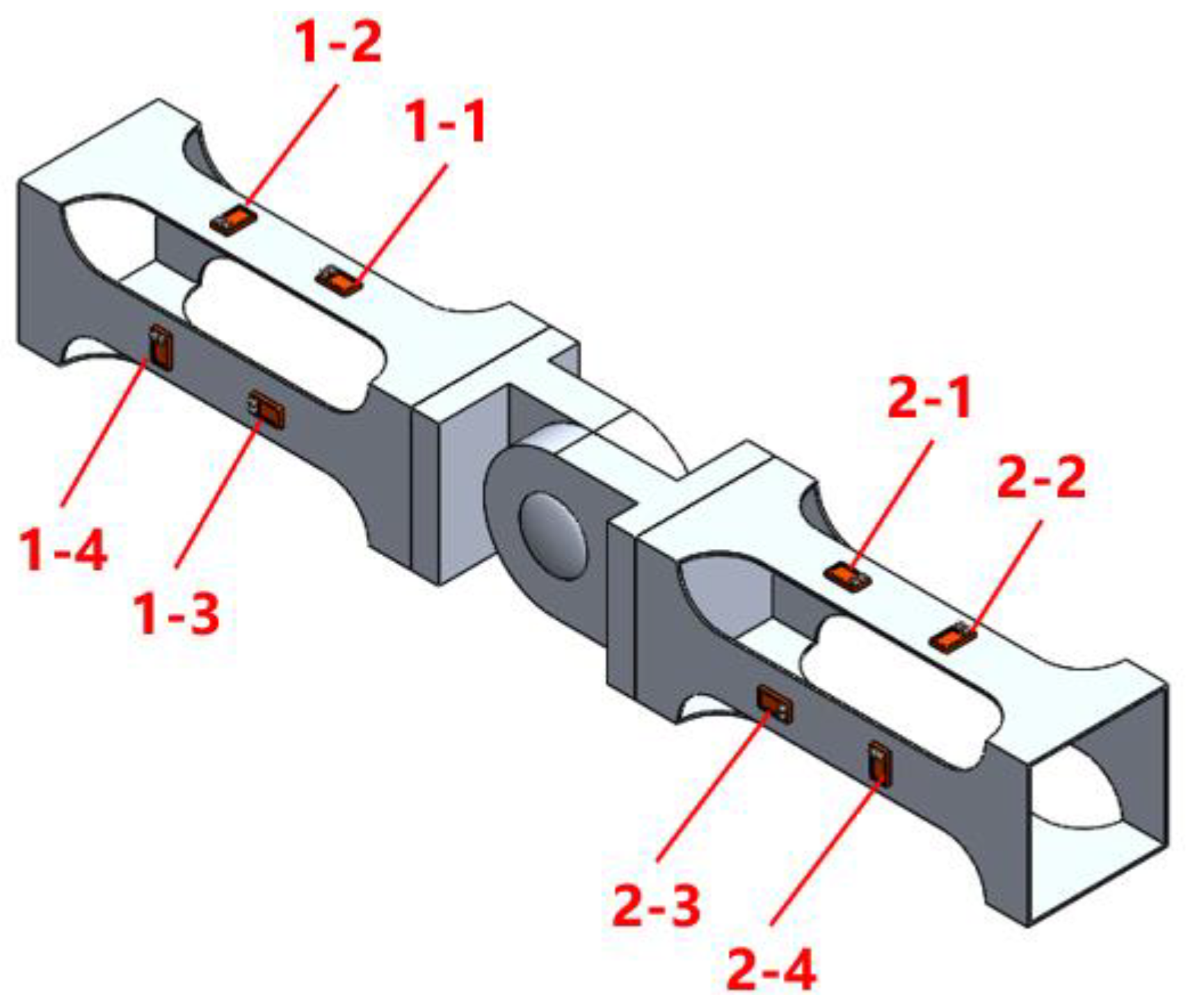
The load characteristics of the double floating body hinged connector are studied by measuring the stress changes of the connector. In order to study the influence of longitudinal stiffness on the load characteristics of hinged connectors, the hinged connector is composed of two symmetrical parts. A single hinged connector includes five parts: hinged head, square pipe, circular flange, longitudinal spring and circular sleeve. The sleeve, hinged head, square pipe and circular flange are all made of 6061 aluminum alloy with elastic modulus E = 68.9   GPa , Poisson’s ratio μ = 0.33 and density ρ = 2.75 × 10 3   kg / m 3 . The three parts of the hinged connector are connected by bolts. To study the load characteristics of hinged connectors, strain gauges need to be arranged on the square tube of the connector. However, if the strength of the square tube is too large, it will make the strain very small, which is not conducive to the measurement of strain. Therefore, a weakening hole is cut on the square tube to meet the measurement requirements of strain gauges. The strain gauge is arranged on a narrow band with a width of 20 mm in the middle of the square tube. The unidirectional strain gauge is arranged in the middle of the square tube of the connector, and the strain gauge is arranged as close as possible to the middle position in the width direction of the connector to improve the accuracy of the strain measurements of the hinged connector. The hinged connector model and the arrangement position of the strain gauges are displayed in Figure 2. No. 1-1, 1-3, 2-1 and 2-3 unidirectional strain gauges are arranged along the connector longitudinal direction for measuring the connector longitudinal strain. No. 1-2 and No. 2-2 unidirectional strain gauges are arranged along the lateral of the connector to measure the lateral strain of the connector. Unidirectional strain gauges 1-4 and 2-4 are arranged along the vertical of the connector to measure the vertical strain of the connector.

2.2. Mooring System

Navigation board and mooring rope are used to restrain the floating body with consideration of the floating body drifting in waves. The navigation board is welded to the floating body, and the mooring rope is fixed to the mooring hole. The navigation board and mooring holes are symmetrically arranged on the nonconnected side of each floating body module, described in Figure 3.
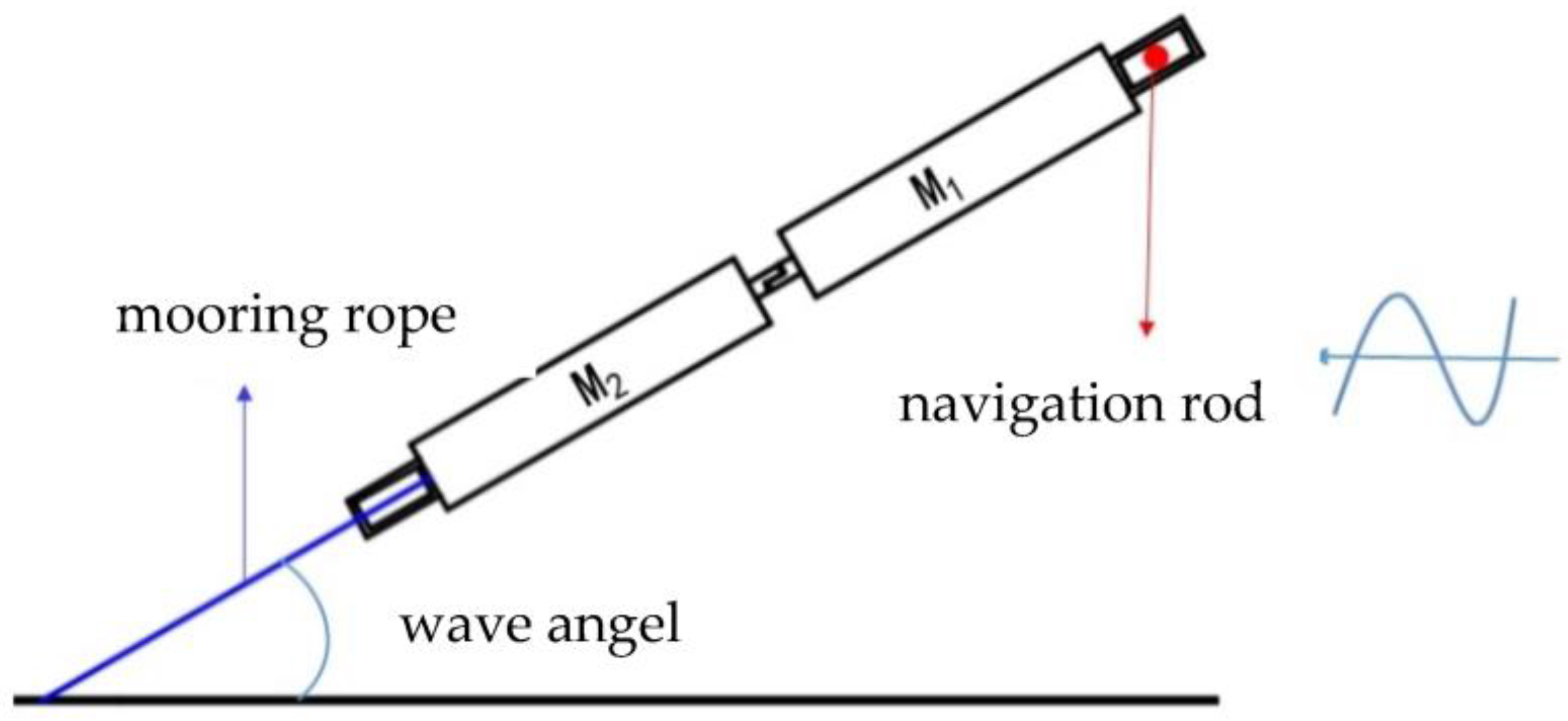
The first module on the wave-facing side is defined as M1, and the other module is defined as M2. The wave-facing condition (wave Angle is 0°) is shown in Figure 4. At this time, the navigation boards of both modules are inserted into the navigation rod, and the mooring rope of module M1 is mooring at the front mooring point of the trailer, while module M2 is not mooring. Under oblique wave conditions, only the navigation board of module M1 is inserted into the navigation rod, and the mooring rope of module M2 is mooring to the side slide of the pool without mooring for module M1, as shown in Figure 5. Before different wave angle conditions, the wave angle is adjusted by changing the mooring position of the mooring rope of module M2.

2.3. Test Conditions

The experiments are carried out in the towing tank in Wuhan University of Technology. The laboratory is equipped with a 24-unit shaking plate wave, which can produce regular waves, two-dimensional constant peak irregular waves, three-dimensional directional waves and a single wave with extreme wave characteristics. The wave height can range from 0.01 m to 0.4 m. The capacitive-type wave probe is equipped, which is mainly used for measuring the water level height. The length of the towing tank is 132 m, the width is 10.8 m and the depth is 2 m. Considering the formation and attenuation of waves, the experiment location is chosen to be near the wave maker in the tank and avoid the wave-making region. The relative position of the floating body and the tank equipment are shown in Figure 6.
The main thing in the design of experiment conditions is to determine the parameters of wave direction, wave height and wave length. Four groups of conditions are designed in the experiments, including variable wave direction, variable wave height, variable wavelength and period. The experiment conditions are listed in Table 2. The width and depth of the floating body module are small, so the deck is likely to be flooded and capsized under dangerous conditions. In consideration of the condition of the variable wave direction, four different wave directions (0°, 15°, 30° and 45°) are designed to study the load characteristics of the hinged connector of a double floating body model under oblique waves. The variable wave height conditions are carried out to ensure that the influence of wave height on the measurement results is in a linear range, so four different wave heights are adopted in the experiments.

3. Numerical Model and Simulation

The three-dimensional potential flow theory for the multi-floating coupling problem is performed to study serial numerical simulations for the load identification of a hinged connector, and the numerical results are obtained and analyzed in this section. In last section, the experiments of a double module floating body with a hinged connector were conducted, and the experiment was a powerful and means method to study the load of a hinged connector, while the cost of the experimental research was high required a lot of manpower, material resources, financial resources and time costs. Numerical simulations are becoming an effective means to make up for the shortcomings of experimental methods with the development of computer technology. The numerical model is closer to the ideal state, which is convenient to study the influence of different variables on the load of the hinged connector in detail. The three-dimensional potential flow theory for the multi-floating body coupling problem is used to simulate experimental conditions. According to the analysis of experimental results and numerical simulation results, the anisotropic load characteristics of the double floating hinged connector are summarized.

3.1. Numerical Simulation Method

The wave load solver AQWA is used to solve the load of a hinged connector with multi-floating bodies based on the commercial platform ANSYS. Firstly, the weight center of gravity and the moment of inertia of the floating body module and the hinged connector are determined, and the hydrodynamic model of the double floating body is established. Secondly, three-dimensional Green’s function is employed to simulate the boundary conditions of the floating body in the flow field, except the surface conditions, and the fluid velocity potential is decomposed into the incident potential, diffraction potential and radiation potential. Based on the impenetrability condition of the surface, the source intensity is arranged on the wet surface of the floating body, and the diffraction potential and radiation potential are solved by three-dimensional source–sink method. After obtaining the velocity potential, the pressure on the wet surface of the floating body is obtained by solving the Bernoulli equations, and the wave-induced load under regular waves can be obtained by integrating the pressure along the wet surface of the floating body. The load of a hinged connector can be gained by solving the displacement continuity condition at the connection point and the motion equation of multiple floating bodies simultaneously based on the Lagrange multiplier algorithm.

3.2. Numerical Model

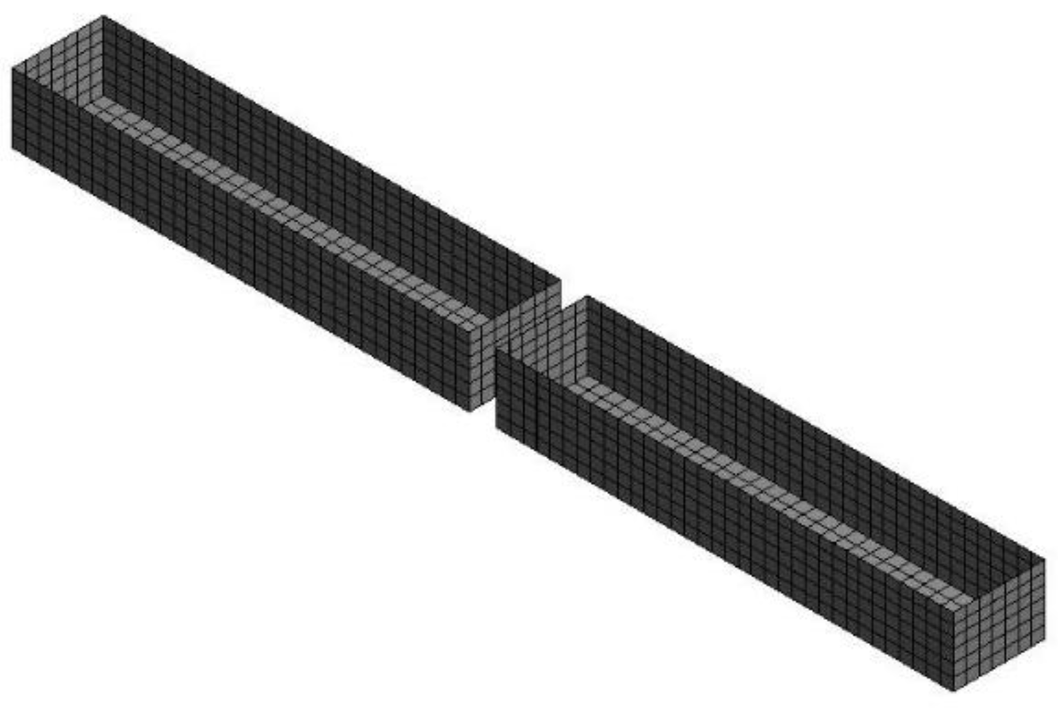
According to the main scale of the experiment floating body module in the last section, the hydrodynamic calculation model is established, as shown in Figure 7. Taking the experimental model as the simulation object, the hydrodynamic models of two rigid floating bodies are established, and the hinged connection mode is set between two floating bodies, ignoring the influence of the wet surface of the connector for the overall wet surface. The hydrodynamic model is divided into a series of surface elements on the outer surface, which can meet the requirement of meshing with at least 7 elements in a wave length range. After checking the convergence, the mesh size of the hydrodynamic model is set as 50 mm, and each floating body is divided into 1460 surface elements in consideration of the calculation accuracy and efficiency.
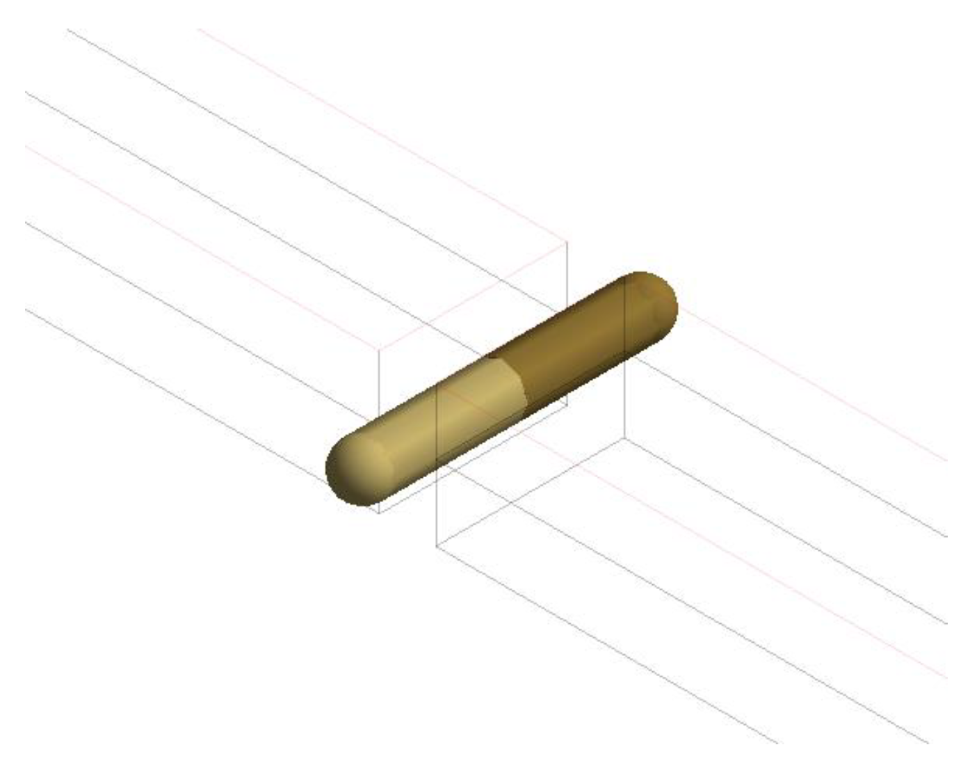
In the ANSYS-AQWA platform, in order to simulate the hinged connection between floating bodies, a hinged joint is set between floating bodies, the horizontal axis rotation between floating bodies is released and the linear degrees of freedom are coupled, as shown in Figure 8.

4. Results and Discussion

In this section, the numerical simulations are carried out for each condition based on the multi-floating coupling 3D potential flow theory. The numerical results are compared with the experimental results. There are four groups conditions, including variable wave height condition, variable wave direction condition and variable wave period condition. The three groups of conditions are numerically simulated, and the results are compared and analyzed with the test results.

4.1. Influence of Wave Height on Load of Hinged Connector

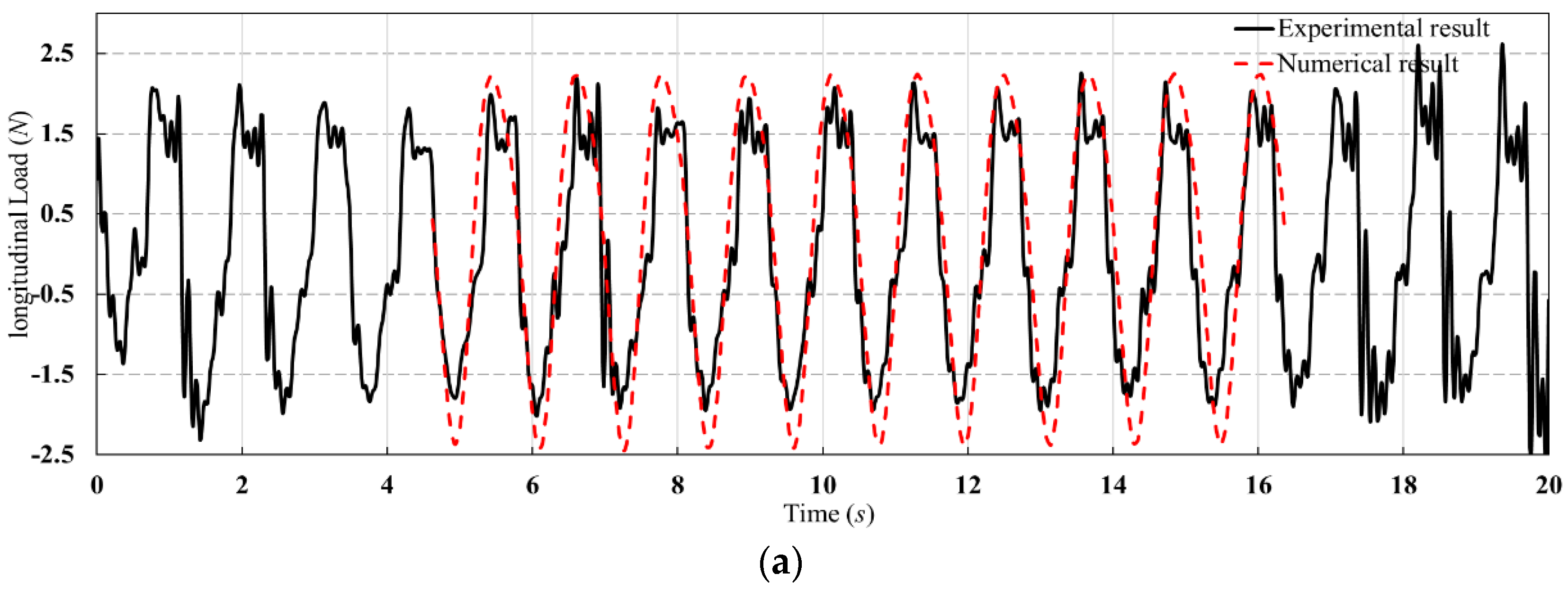
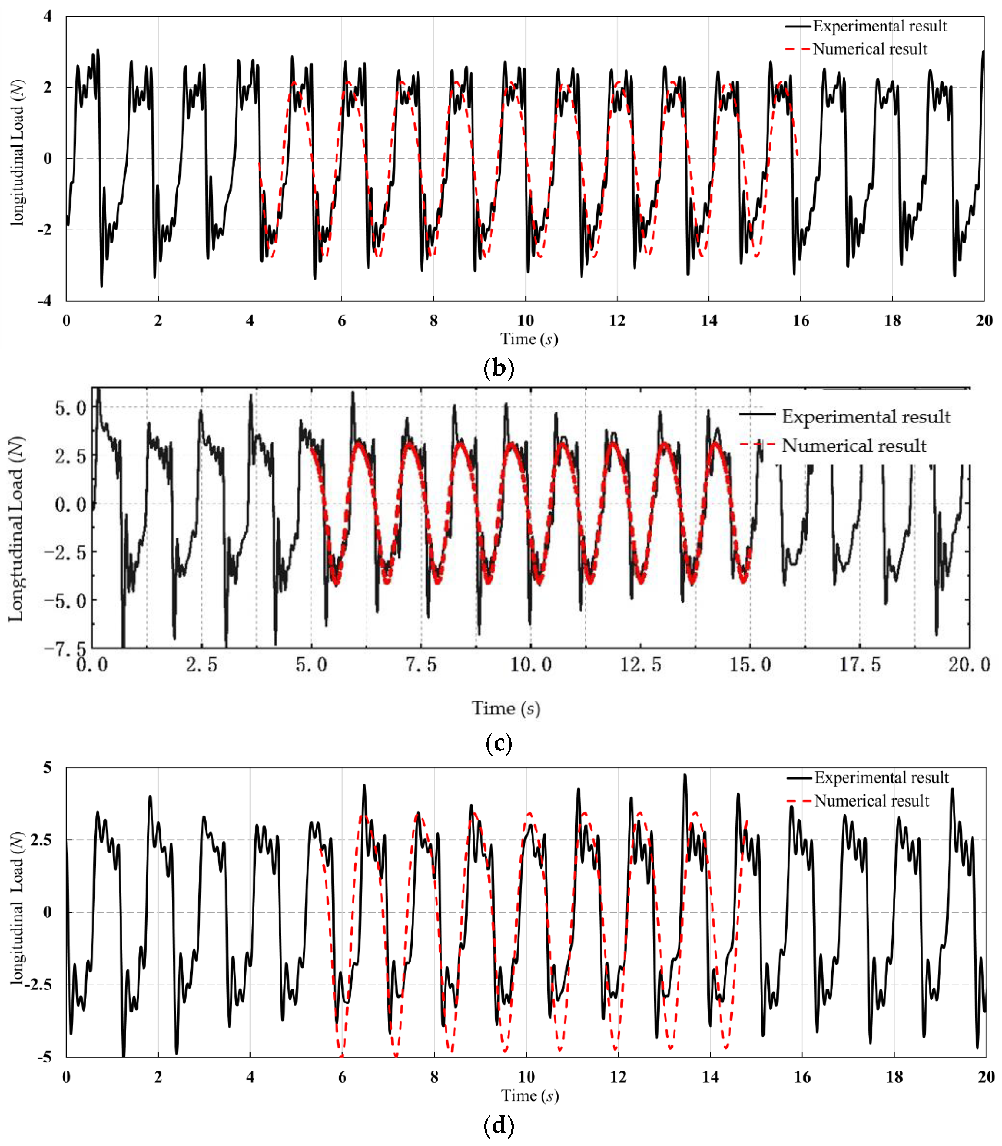
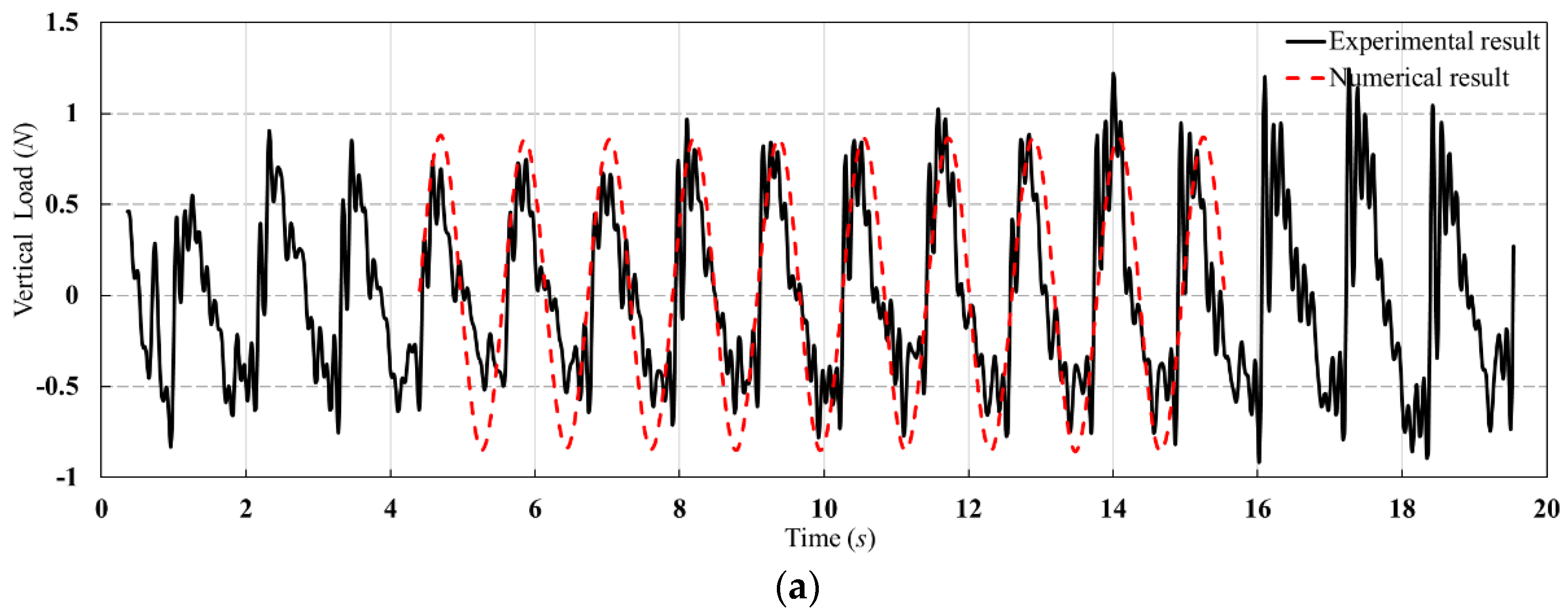
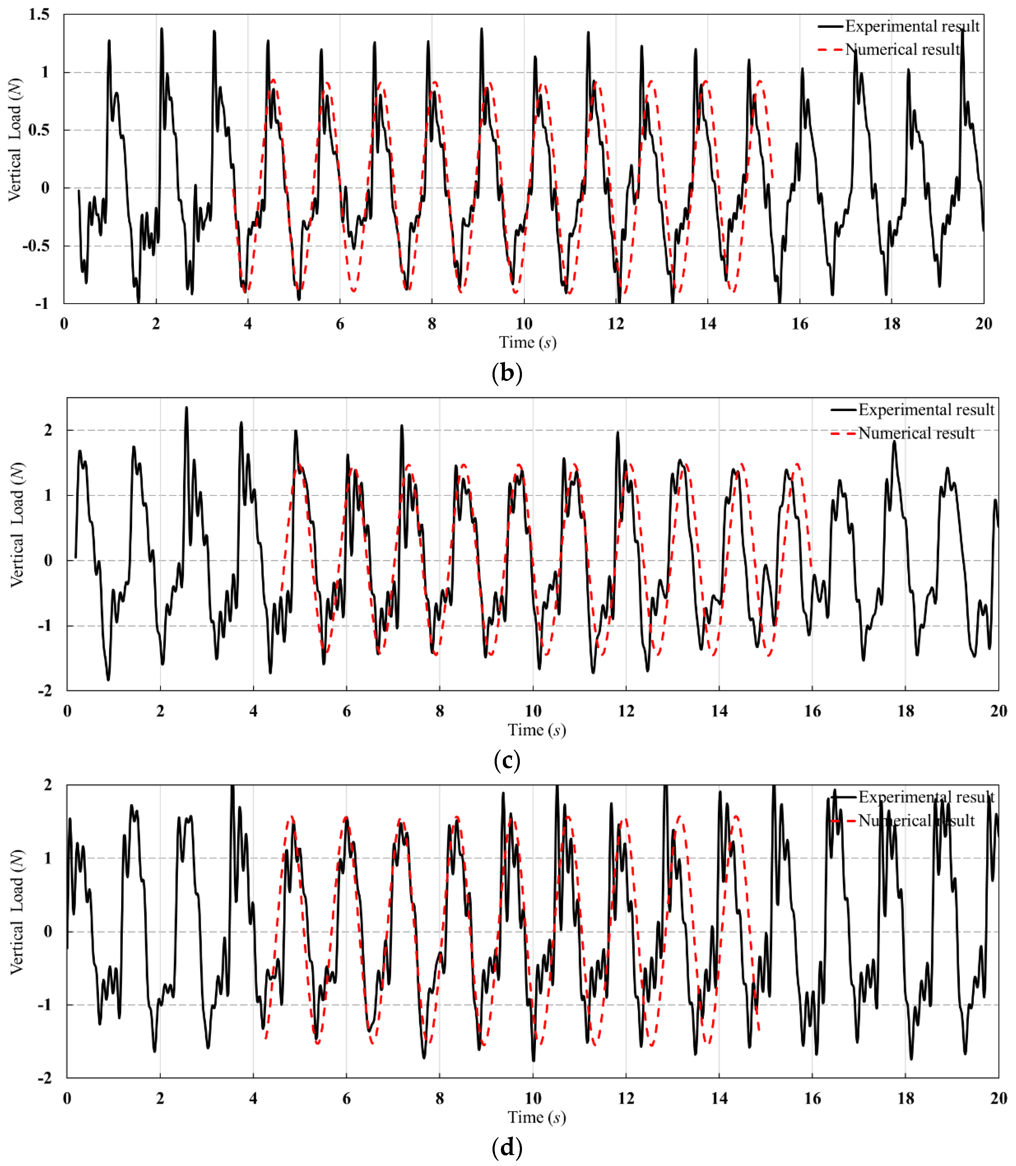
In order to study the influence of wave height on the load of a hinged connector, the experiments are carried out in conditions height-1~height-4. Figure 9 and Figure 10 show the longitudinal and vertical load time histories of the experimental and numerical results, respectively. The curve of the simulation results is slightly smooth. The longitudinal and vertical loads on the hinged connector are increased with the wave height gradually from height-1~height-4. The period of the curve is almost the same. There shows a small amount of slamming peak in the time history. It is assumed that the slamming and the influence of fluid viscosity cannot be considered by the linear potential flow theory based on the ANSYS platform. It is found that the results of the longitudinal load are not appropriate in the case of height-4, as the errors between the experimental results and the simulation results are obvious. It is considered that the viscos effect increases with the load value. The vertical load time history is almost closed. It is stated that the viscous effect is relatively small for the vertical load evaluation. As the wave conditions of height-1~height-4 are wave-facing, the transverse load of the connector is small and irregular, since it is not analyzed here.
Figure 11 shows the longitudinal and vertical loads of the hinged connector under different wave heights. It can be seen that the load increases with the wave height linearly, indicating the validity of the data. For the longitudinal load, the results are almost same. For the vertical load, there is small gap between the numerical results and experimental results that is acceptable. For the simulations, the numerical method applied in the ANSYS platform is based on the 3D potential flow theory and ignores the influence of the fluid viscosity; thus, the load obtained by the numerical simulation is a little large, which can be seen from the figure. For the experiments, there are many connections between the strain gauge and the dynamic strain gauge in the experiment. The connection is wrapped with rubber and suspended above the model vertically, which affects the vertical motion of the floating body in the wave and causes the reaction force of the connection during the vertical motion of the model, and the experimental measurement value of the vertical load of the connector is small. The value of the vertical load is much smaller, which means it is affected dramatically by a little deviation.

4.2. Influence of Wave Period on the Load of Hinged Connector

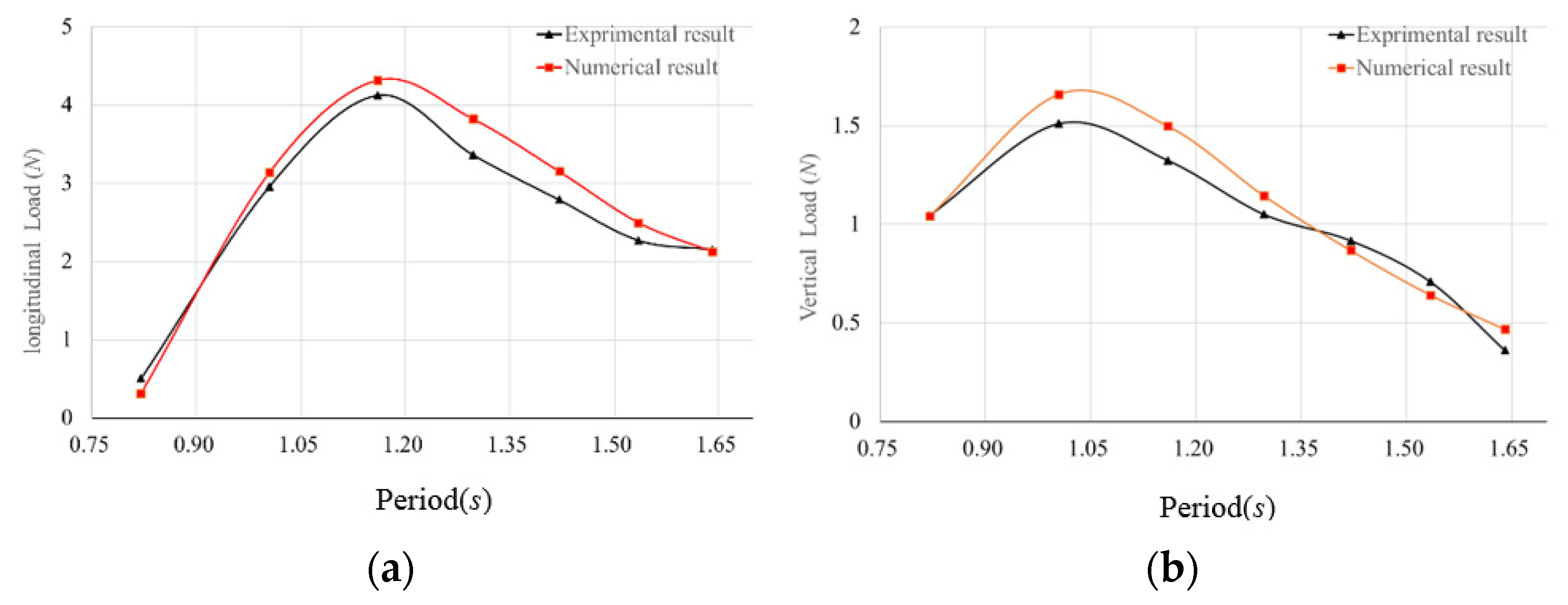
Figure 12 shows that the longitudinal load of the hinged connector first increases gradually with the increase of the regular wave period, and the maximum value occurs when the period is 1.16 s; that is, the ratio of wavelength and module length is about two. Then, it decreases gradually with the increase of the wave period. The vertical load also increases gradually with the increase of the wave period, and the maximum value appears when the period is 1.0046 s; that is, the ratio of wave length and module length is about 1.5 and then decreases gradually with the increase of wave period. It is indicated that the structural natural frequency is in accordance with the wave frequency, and the value of the load will reach the maximum value. It is illustrated that, when the wave period is in accordance with the structural natural frequency, the value of the load reaches the maximum value.

4.3. Influence of Wave Direction Angle on the Load of Hinged Connector

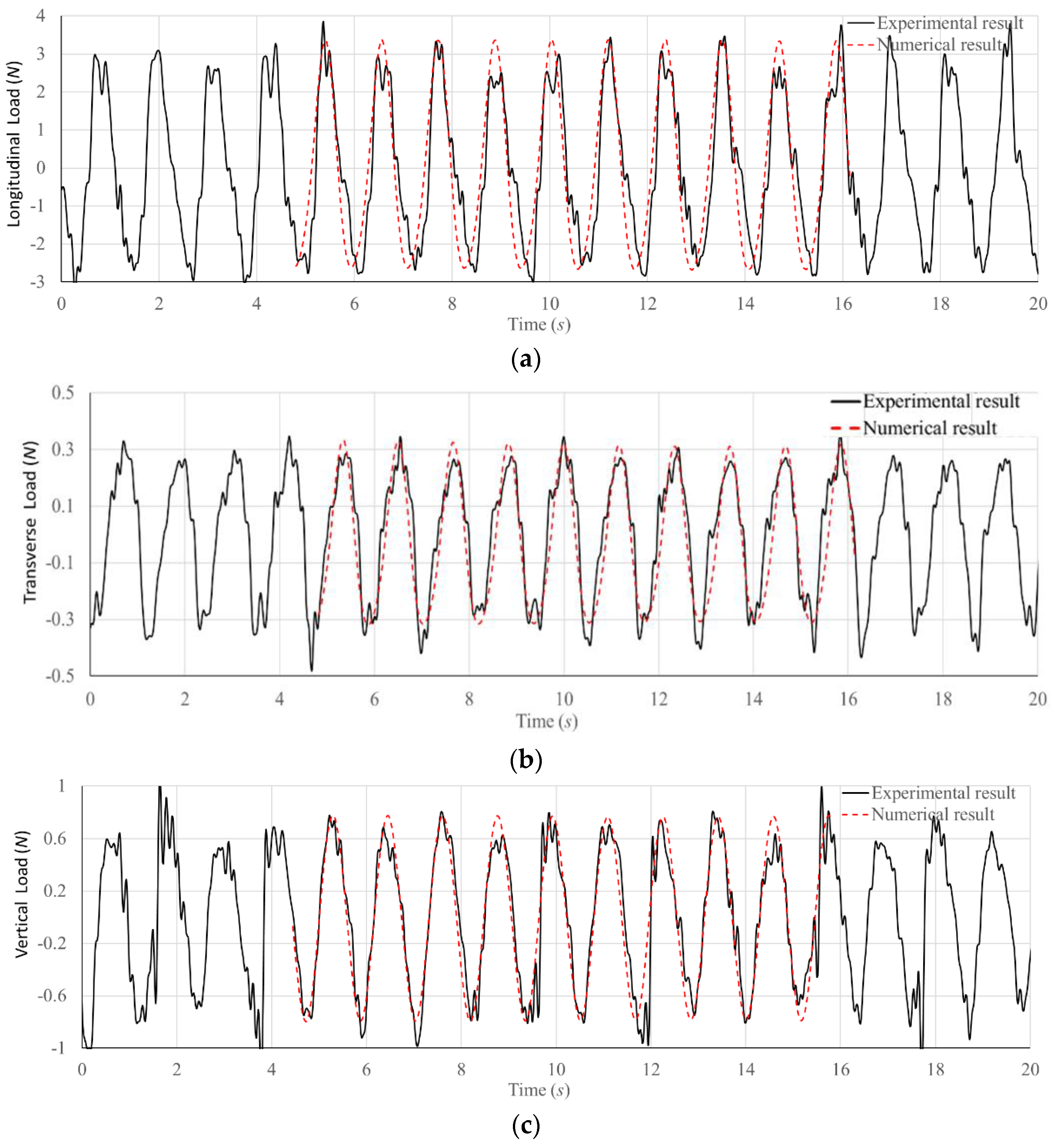
It may cause water intake or even capsizing in a large wave angle. For the safety of the test, four wave direction angles of 0°, 15°, 30° and 45° were designed for the test. In the numerical simulation, the numerical simulations under the wave direction angles of 60°, 75° and 90° were added. Figure 13 shows the load time history of the experimental and numerical results at wave angle 30°, it was found that they are almost the same. In consideration of wave angle 30°, the transverse load was generated but was a bit small. The longitudinal load was much larger than the transverse load and vertical load, because the effect of the wave was obvious in the longitudinal direction.
Furthermore, the load of the hinged connector under different wave angles was analyzed statistically. It is obtained in Figure 14. Between the 0° and 90° wave directions, the longitudinal and vertical loads of the hinged connector gradually decrease with the increase of the wave angle. The lateral load increases with the wave angle gradually before the 30° wave direction, and the maximum appeared around the 30° wave direction, decreasing with the increase of the wave angle gradually. The load on the connector comes from the relative motion between the double module floating bodies. Under the condition of the transverse wave with a 90° wave direction, the motion responses of the two floating bodies in the wave were similar due to the symmetry of the wet surface. The load on the hinged connector was not large in each direction.

5. Conclusions

In this paper, the experiments for double floating bodies connected by a hinged connector were conducted in different conditions. The experiments provided a way to study the load characteristics of a hinged connector for a double floating model induced by waves. A double floating model with a hinged connector was designed, experimental cases were determined and a number of wave models were selected. The experiment was completed by changing the wave characteristics and with/without longitudinal springs. The experimental measurements of a hinged connector for double floating bodies were conducted in all wave directions and to compare and validate the numerical modeling and simulations. The study resulted in the following conclusions:
(1) When the wave height and wave length are certain values, the longitudinal and vertical loads of the hinged connector are the maximum at a wave direction of 0°, and the transverse loads are the maximum at a wave direction of 30°.
(2) When the wave height is the same and the wave direction is a 0° angle, the maximum longitudinal load of the hinged connector occurs at the ratio between the wave length and one module length is 2, and the maximum vertical load that occurs at the ratio between the wave length and one module length is 1.5.
(3) The wave load solver AQWA, which is based on the 3D potential flow theory, ignores the influence of fluid viscosity; thus, it is not suitable for the numerical calculation of the vertical load. It can be used as a rapid assessment method for the load estimation. For further research, the computational fluid dynamics method is recommended in the case of the consideration for the influence of fluid viscosity.

Author Contributions

Conceptualization, W.L. and X.S.; methodology, W.L.; software, H.W. and X.S.; validation, W.L.; formal analysis, X.S. and H.W.; investigation, X.S.; resources, X.S.; data curation, X.S.; writing—original draft preparation, X.S.; writing—review and editing, X.S.; supervision, W.L. All authors have read and agreed to the published version of the manuscript.

Funding

This research was funded by the National Natural Science Foundation of China grant number No. 52101371 and No. 52071243 and National Defense Basic Research Program of China (No. JCKY2020206B037).

Institutional Review Board Statement

Not applicable.

Informed Consent Statement

Not applicable.

Data Availability Statement

Data is unavailable due to privacy or ethical restrictions.

Acknowledgments

The authors would like to acknowledge the support of the National Natural Science Foundation of China (No. 52101371 and No. 52071243) and the National Defense Basic Research Program of China (No. JCKY2020206B037).

Conflicts of Interest

The authors declare no conflict of interest.

References

  1. Remmers, G.; Zueck, R.; Palo, P.; Taylor, R. Mobile offshore base. In Proceedings of the 1998 8th International Offshore and Polar Engineering Conference, Part 1 (of 4), Montreal, QC, Canada, 24–29 May 1998. [Google Scholar]
  2. Yoshida, K. Developments and research on VLFS in Japan. In Proceedings of the Second International Work Shop on Very Large Floating Structures, Hayama, Japan, 25–28 November 1996; p. 4522. [Google Scholar]
  3. Riggs, H.R.; Ertekin, R.C.; Mills, T.R.J. Impact of connector stiffness on the response of a multi-module mobile offshore base. In Proceedings of the International Offshore and Polar Engineer Conference, Montreal, QC, Canada, 24–29 May 1998; ISOPE: Mountain View, CA, USA, 1998; Volume 1, pp. 200–207. [Google Scholar]
  4. Suzuki, H. Safety target of very large floating structure used as a floating airport. Mar. Struct. 2001, 14, 103–113. [Google Scholar] [CrossRef]
  5. Suzuki, H.; Harada, H.; Natsume, T.; Maeda, K.; Iijima, K.; Hayashi, T. Technical Challenge on VLFS in JapanAfter Mega-Float Project. In Proceedings of the ASME 2017 36th International Conference on Ocean, Offshore and Arctic Engineering, Trondheim, Norway, 25–30 June 2017; p. V009T12A013. [Google Scholar]
  6. Suzuki, H. Overview of Megafloat: Concept, design criteria, analysis, and design. Mar. Struct. 2005, 18, 111–132. [Google Scholar] [CrossRef]
  7. Riggs, H.R.; Ertekin, R.C. Approximate methods for dynamic response of multi-module floating structures. Mar. Struct. 1993, 6, 117–141. [Google Scholar] [CrossRef]
  8. Pathak, M. Effects of Wave Length, Water Depth, Aspect Ratio and SlopigSeabed on Hydroelastic Response of VLFS; National University of Singapore: Singapore, 2014. [Google Scholar]
  9. Spry, S.; Hedrick, K. A Centralized Control Strategy for a Mobile Offshore Base. In Proceedings of the American Control Conference, San Diego, CA, USA, 2–4 June 1999. [Google Scholar]
  10. Zueck, R.; Taylor, R.; Palo, P. Assessment of Technology for Mobile Offshore Base. In Proceedings of the International Offshore and Polar Engineering Conference, Seattle, DC, USA, 28 May–2 June 2000. [Google Scholar]
  11. Palo, P.A.; Taylor, R.; Brackett, R.; Zueck, R. Contributions to offshore engineering from the mobile offshore base program. In Proceedings of the International Conference on Offshore Mechanics and Arctic Engineering, Rio de Janeiro, Brazil, 3–8 June 2001. [Google Scholar]
  12. Girard, A.R.; de Sousa, J.B.; Hedrick, J.K. Dynamic Positioning Concepts and Strategies for the Mobile Offshore Base. In Proceedings of the IEEE Intelligent Transportation Systems Conference, Oakland, CA, USA, 25–29 August 2001. [Google Scholar]
  13. Rognaas, G.; Xu, J.; Lindseth, S.; Rosendahl, F. Mobile offshore base concepts Concrete hull and steel topsides. Mar. Struct. 2001, 14, 5–23. [Google Scholar] [CrossRef]
  14. Drummen, I.; Olbert, G. Conceptual design of a modular floating multi-purpose island. Front. Mar. Sci. 2021, 8, 615222. [Google Scholar] [CrossRef]
  15. McAllister, K.R. Mobile Offshore Base-An Overview of Recent Research. In Proceedings of the International Workshop On Very Large Floating Structures, Hayama, Japan, 25–28 November 1996; pp. 69–76. [Google Scholar]
  16. Wang, C.M.; Tay, Z.Y. Very large floating structures: Applications, research and development. Procedia Eng. 2011, 14, 62–72. [Google Scholar] [CrossRef] [Green Version]
  17. Wang, Z.J.; Li, R.P.; Shu, Z. Technical problems in the conceptual design of very large floating structures. Ocean. Eng. 2001, 19, 1–6. (In Chinese) [Google Scholar]
  18. Wung, C.C.; Manetas, M.; Ying, J. Hydrodynamic computational tools validation against mobile offshore base model testing. In Proceedings of the Third International Workshop on Very Large Floating Structure, Honolulu, HI, USA, 22–24 September 1999; Volume 2, pp. 538–545. [Google Scholar]
  19. Lv, H.; Yang, J.; Zhang, C. Experimental study of multi-rigid body for semi-submersible super-large floating body. Ship Eng. 2004, 5, 33–37. [Google Scholar]
  20. Ding, W.; Yu, L.; Li, R.P.; Yao, M.W. Dynamic response experiment of connector for mobile offshore base. Ocean. Eng. 2005, 23, 11–15. [Google Scholar]
  21. Wu, Y.S.; Gu, X.K.; Liu, S.X.; Tian, C.; Wang, X.F.; Cheng, X.M.; Qi, E.R. Advances of basic research on the responses and safety of very large floating structures in complicated environment. China Basic Sci. 2017, 19, 28–44. (In Chinese) [Google Scholar]
  22. Cui, W.C.; Wu, Y.S.; Li, R.P. Recent researches on dynamic performances of very large floating structures. J. Ship Mech. 2001, 5, 73–81. (In Chinese) [Google Scholar]
  23. Riggs, H.R.; Ertekin, R.C.; Mills, T.R.J. Characteristics of the wave response of Mobile Offshore Base. In Proceedings of the 18th International Conference on Offshore Mechanics and Arctic Engineering, St. Johns, NL, Canada, 11–16 July 1999; pp. 1–9. [Google Scholar]
  24. Zhang, X. Study on Configuration and Load of Multi-Module Very Large Floating Body. Ph.D. Thesis, China Ship Research Institute, Wuxi, China, 2018. [Google Scholar]
  25. Wang, W. Design and Load Analysis of Multi-Body Super Large Floating Structure Connectors. Ph.D. Thesis, Jiangsu University of Science and Technology, Zhenjiang, China, 2014. [Google Scholar]
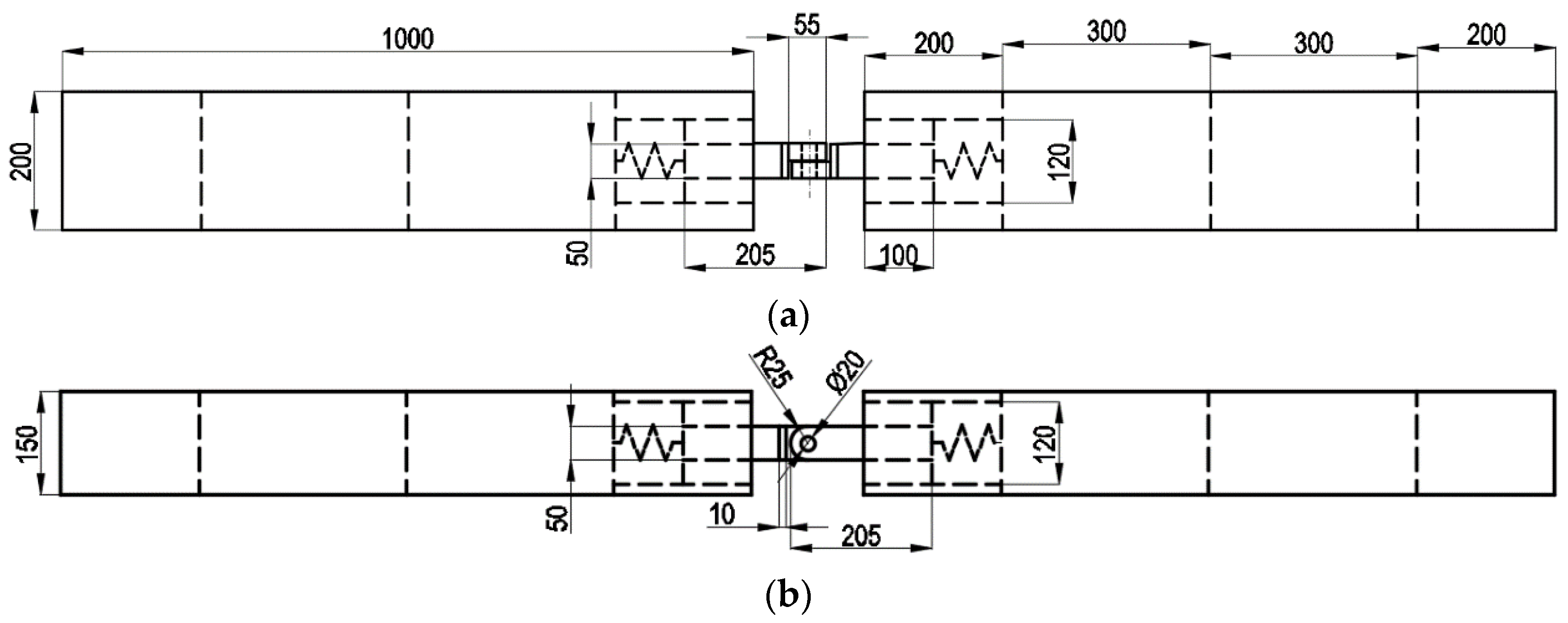
Figure 1. Model of double module box floating structure: (a) top view; (b) front view.
Jmse 11 00786 g001
Figure 2. Hinged connector model and strain gauge placement.
Jmse 11 00786 g002
Figure 3. The mooring system and the floating body. (a) The navigation board. (b) The mooring system.
Jmse 11 00786 g003
Figure 4. Mooring scheme under a head wave.
Jmse 11 00786 g004
Figure 5. Mooring scheme under an oblique wave.
Jmse 11 00786 g005
Figure 6. Relative position of the model and the tank equipment.
Jmse 11 00786 g006
Figure 7. Hydrodynamic model.
Jmse 11 00786 g007
Figure 8. The spring system of a hinged connection.
Jmse 11 00786 g008
Figure 9. The longitudinal load time history in conditions height−1~height−4: (a) height−1; (b) height−2; (c) height−3; (d) height−4.
Jmse 11 00786 g009aJmse 11 00786 g009b
Figure 10. The vertical load time history in conditions height−1~height−4: (a) height−1; (b) height−2; (c) height−3; (d) height−4.
Jmse 11 00786 g010aJmse 11 00786 g010b
Figure 11. Loads on the hinged connector: (a) longitudinal load; (b) vertical load.
Jmse 11 00786 g011
Figure 12. Loads on the hinged connector: (a) longitudinal load; (b) vertical load.
Jmse 11 00786 g012
Figure 13. The load time history in condition direction−3: (a) longitudinal load; (b) transverse load; (c) vertical load.
Jmse 11 00786 g013
Figure 14. Loads on the hinged connector: (a) longitudinal load; (b) transverse load; (c) vertical load.
Jmse 11 00786 g014
Table 1. Main dimensions of a single module model.
Main ParameterValue
Length1000 mm
Width200 mm
Height150 mm
Draft80 mm
Displacement16 kg
Table 2. Experiment conditions.
No.Wave Direction °Wave Height mWave Length/One ModulePeriod s
Height-100.01521.160
Height-200.02021.160
Height-300.02521.160
Height-400.03021.160
Length-100.02510.820
Length-200.0251.51.005
Length-300.02521.160
Length-400.0252.51.297
Length-500.02531.421
Length-600.0253.51.535
Length-700.02541.641
Direction-100.02521.160
Direction-2150.02521.160
Direction-3300.02521.160
Direction-4450.02521.160
Disclaimer/Publisher’s Note: The statements, opinions and data contained in all publications are solely those of the individual author(s) and contributor(s) and not of MDPI and/or the editor(s). MDPI and/or the editor(s) disclaim responsibility for any injury to people or property resulting from any ideas, methods, instructions or products referred to in the content.