Article

Subassembly Partition of Hull Block Based on Two-Dimensional PSO Algorithm

1
School of Naval Architecture and Ocean Engineering, Dalian University of Technology, Dalian 116024, China
2
State Key Laboratory of Structural Analysis for Industrial Equipment, Dalian University of Technology, Dalian 116024, China
3
Collaborative Innovation Center for Advanced Ship and Deep-Sea Exploration, Shanghai 220240, China
*
Author to whom correspondence should be addressed.
J. Mar. Sci. Eng. 2023, 11(5), 1006; https://doi.org/10.3390/jmse11051006
Submission received: 22 March 2023 / Revised: 4 May 2023 / Accepted: 6 May 2023 / Published: 8 May 2023
(This article belongs to the Section Ocean Engineering)

Abstract

:
Subassembly partition is an important process in hull block building as it greatly affects the efficiency and quality of the assembly work. Recently, an experience-based method has been widely applied to the subassembly partition process, which consumes much design time and manpower, thus causing more challenges toward a more highly automated and efficient stage in this process. To shorten the gap, an automated subassembly partition method is presented in this study. First, the assembly information model is defined with essential attributes and topological relations of the parts. Second, an optimization model is established with consideration of a trade-off between the intra-cluster cohesion and cluster number on the premise of satisfying certain constraints. After that, considering the fuzziness and diversity of the subassembly partition problem, a two-dimensional coding discrete particle swarm optimization (PSO) algorithm is developed. Finally, two blocks are demonstrated as instances to verify the proposed method, and the results show that the proposed method is feasible and applicable to the block with a flat structure.

1. Introduction

A hull block is an important intermediate product in the process of shipbuilding, which refers to the assembly of a number of steel plates and sections on the molding bed or platform through welding operation [1]. The block construction is the most important process, the hours and costs of which respectively account for 40~60% and 30~50% of the total hours and costs of hull building [2]. Nowadays, with the development of ship-building technology, blocks gradually evolve toward larger sizes and more complex structures, which brings more challenges to the assembly sequence planning (ASP) process [3]. Because the search space of the assembly sequence increases exponentially with the number of parts and the assembly relations between the parts, this leads to a large amount of computation time and memory space being consumed [4]. To reduce the complexity of ASP and simplify the assembly process, subassembly partition needs to be implemented. Based on generated subassemblies, the difficulty of ASP is effectively simplified, and the parallelism of the assembly process is improved accordingly.
The subassembly can be regarded as a stable structure composed of two or more parts, which can be fabricated at the previous assembly process. A reasonable subassembly assignment can ease the operational difficulty, shorten the assembly time, and minimize the whole cost of manufacturing [5]. In most shipyards, such an assignment is still implemented manually depending on the experiences and know-how of the processing engineering, which increases the redundant work and prolongs the process planning cycle [6], thus hindering the progress toward a higher automated and efficient stage. Therefore, it is urgent to develop an effective method to achieve automatic subassembly generation for ship block building.
Either ASP or subassembly identification, the digital expression of assembly information, is the most critical foundation for obtaining feasible or optimal assembly solutions [7]. Expression methods can be divided into two basic categories: a graph-based method and a matrix-based method [8]. The graph-based method is the most intuitive approach to represent the assembly models, in which the nodes imply the parts or components, and the lines represent the contact information between the parts. Based on this, the weight and direction of the lines are introduced into the liaison diagram to enrich the assembly information. For example, the assembly precedence of the parts can be represented as the arrow direction of the lines [9], and the contact mode or assembly time can also be recorded as the weight of the lines [10]. The matrix-based method is used to represent the assembly information in the form of a digital matrix, which generally includes a liaison matrix, a stability matrix, a priority matrix, an interference matrix, etc. The matrix-based assembly expression method is widely used for ASP since its simple structure is convenient for storage and computation [8].
From the perspective of engineering, subassembly partition is regarded as a decomposition of the product into several smaller units according to certain structural features, functional requirements, production conditions, and assembly constraints for the purpose of reducing the assembly difficulty, expanding the work areas, and improving the assembly efficiency [11]. Homem [12] first defined the subassembly as a stable part set, which can be viewed as an integral part of ASP. He developed a cut-set method for detecting subassemblies and used an And/Or graph to demonstrate the assembly sequence. Theoretically, the cut-set method has the ability to detect all the possible subassemblies of the product, but it is prone to combination explosion with an increase in the parts number, and it requires further identification to generate optimal subassemblies [13]. Li et al. [14] proposed a weight network to represent the topological structure, in which the weights of the edges are brought to illustrate the correlation strengths among the components, and improved the Girvan–Newman algorithm to establish module detection. Belhadj et al. [15] developed a base part determination method to generate effective subassemblies by analyzing the contacts and geometrical feasibilities of the parts. The method greatly reduces the search space of the subassembly partition process. Gulivindala et al. [16] classified the contact stabilities between parts and used stability predicates to perform subassembly detection. The method is effective for specific products with irregular contact surfaces.
From the mathematical perspective, subassembly partition can be regarded as the clustering of parts according to their feature similarities [17]. Zhong et al. [18] introduced a fuzzy cluster analysis algorithm to discover the proper subassemblies. The algorithm can easily obtain all the feasible partition schemes by adjusting the threshold of the fuzzy cut-set matrix. Kou et al. [19] realized subassembly recognition by iterating and updating the center and fuzzy membership degree matrix of subassemblies. Zhang et al. [20] employed a Markov clustering algorithm to discover the candidate subassemblies. The algorithm scales well with increasing graph size and has excellent robustness against noise in graph data. For these clustering-based methods, it is essential and critical to initialize the distance or similarity matrix of the parts, which may directly affect the rationality of the clustering results. Therefore, a great challenge exists in formulating an appropriate evaluation method for the distance and similarity of parts concerning adequate assembly constraints.
In recent years, some researchers have aimed to apply a knowledge-based reasoning method to generate feasible subassemblies. Qiao et al. [21] proposed an ontology model for assembly operation and established a reasoning mechanism to infer the assembly sequence. Shi et al. [22] constructed an assembly semantic model and deduced the weighted assembly-directed graph through semantic web rule language. The semantic-based method has sufficient representation capacity for entitles, relations, and constraints, and it has good performance in subassembly recognition. However, the method is customized solely according to the manufacturing characteristics of products, thus having limited generality—the potential of replication in other industries. Moreover, the challenges in building the semantic model and the huge manpower required in the instantiation of products also add to its limitation.
Recently, heuristic algorithms have been gradually applied to solve ASP problems. Typical heuristic algorithms include the genetic algorithm (GA) [23], the particle swarm optimization algorithm (PSO) [24], the ant colony optimization algorithm (ACO) [25], and other evolutionary algorithms [26]. Theoretically, heuristic algorithms search for an optimal assembly sequence through iterative computation under determined constraints and objective functions. Prematurity and slow convergence are the major subjects to be improved in heuristic algorithms. Li et al. [27] introduced the modified evolutionary direction operator into the PSO algorithm to avoid a local convergence problem in ASP. Yang et al. [28] introduced bacterial chemotaxis into the PSO algorithm, and the new algorithm keeps a more rapid convergence while preventing premature convergence. Rashid [25] incorporated the leadership hierarchy concept from the gray wolf optimizer into the ACO algorithm to enhance the algorithm’s performance. Generally, heuristic algorithms have good performance in solving the serial ASP problem, while they are rarely applied to subassembly partition. Because subassembly partition is a discrete-nonlinear planning process, in which both the group number and member number in each group are fuzzy and ambiguous.
Up to now, researches on the subassembly partition of mechanical products significantly dominate over those dedicated to hulls and marine structures [29]. Adapting the reported methods used for mechanisms to shipbuilding is not always possible due to their specificity regarding the product structure and assembly technologies. To fill this gap, a new subassembly partition method focusing on hull block building is proposed in this study, and a two-dimensional coding PSO algorithm is designed to search for the optimal subassemblies.
The rest of this paper is organized as follows: Section 2 demonstrates an assembly information model based on the essential attributes and topological relations of the parts; Section 3 shows an optimization model for subassembly generation, with consideration of a trade-off between intra-cluster cohesion and clusters number on the premise of satisfying certain constraints; Section 4 proposes a two-dimensional PSO algorithm to search for the optimal solutions of the problem; Section 5 explores two cases to verify the proposed method; and, finally, the conclusion and future expectation are provided in Section 6. Figure 1 shows the strategy of the subassembly partition method proposed in this research.

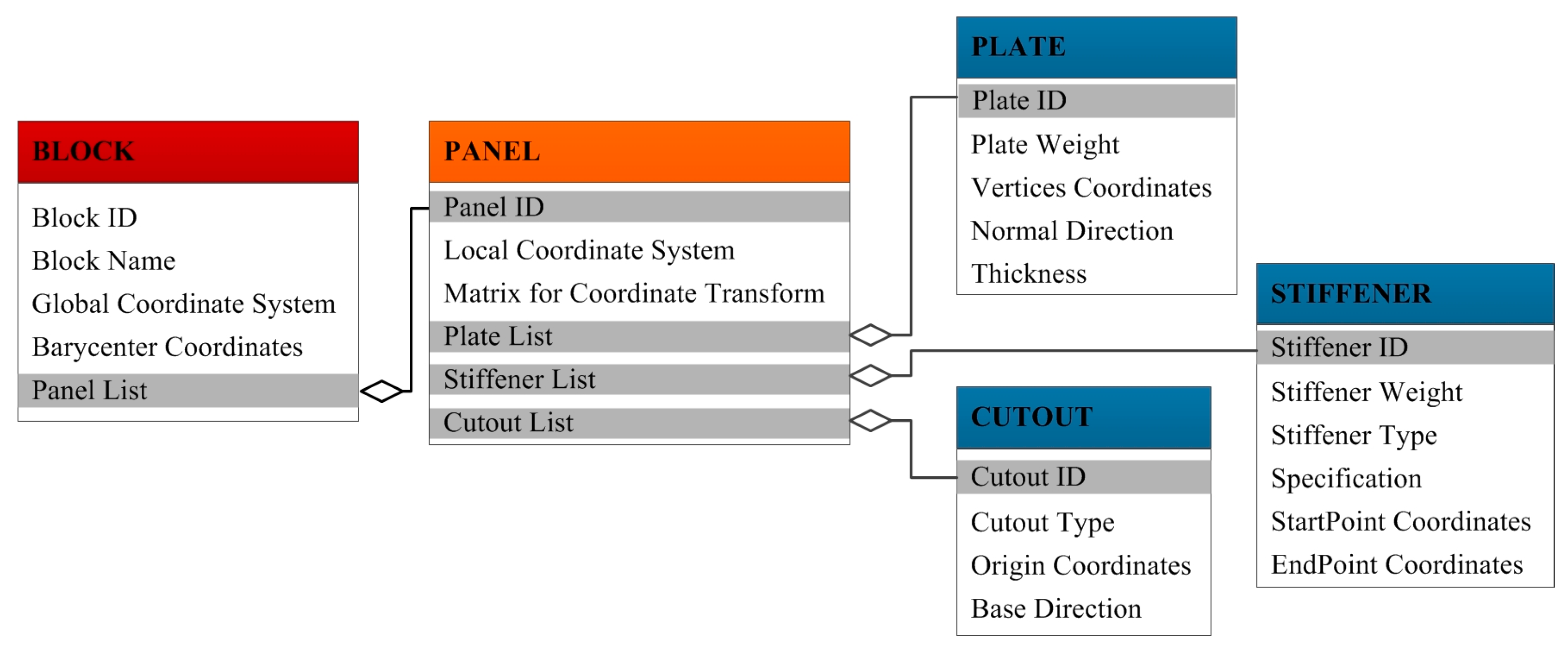
2. Assembly Information Modeling

At the beginning of subassembly identification, it is necessary to reconstruct the corresponding assembly information through a CAD model [30]. In this study, the assembly information required by subassembly partition could be classified into two categories: part information and assembly topology information. The former involves the geometric and physical attributes of the parts, such as vertices, edges, positions, weights, types, etc., while the latter involves the connection relation and interference relation among the parts.

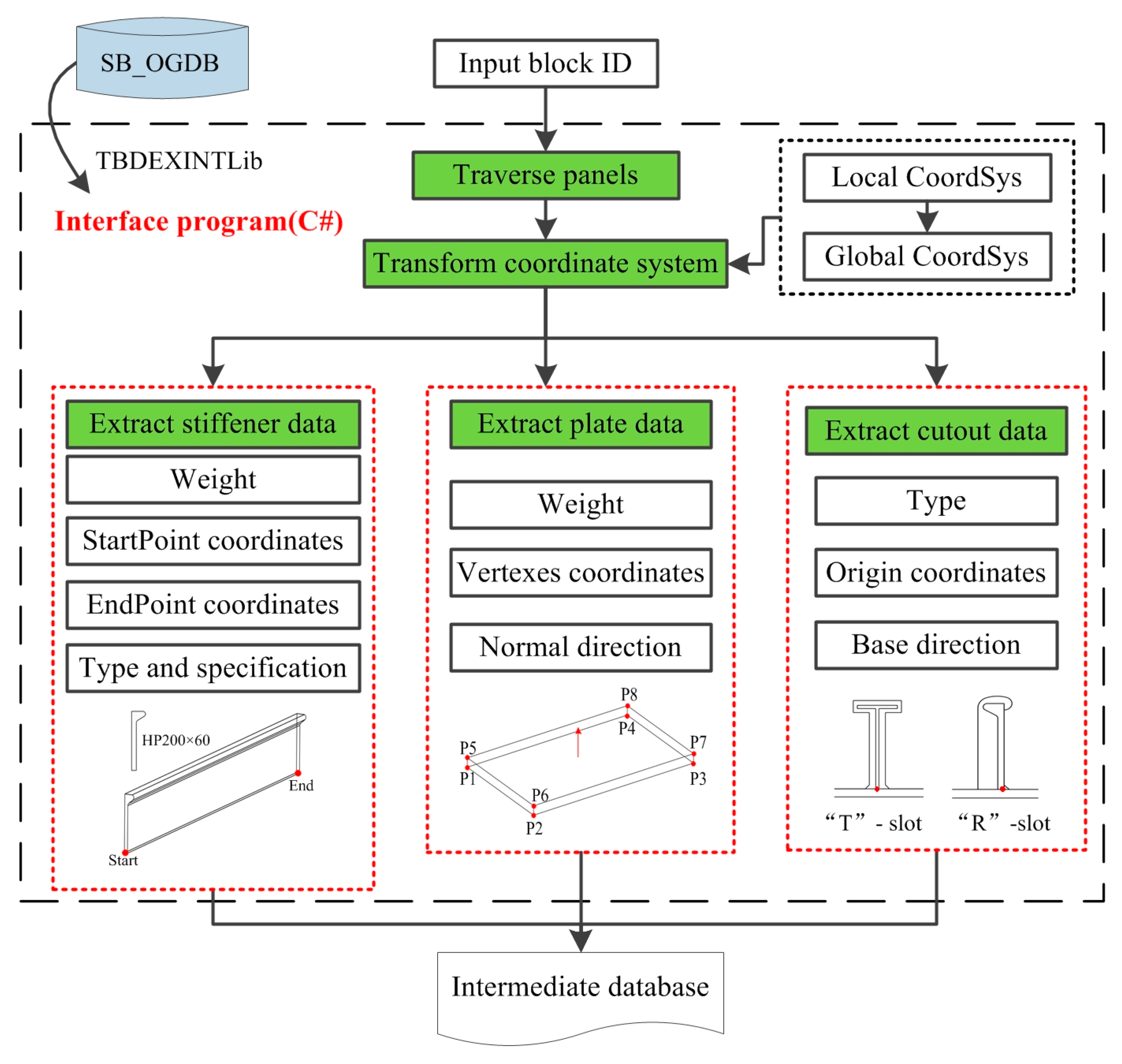
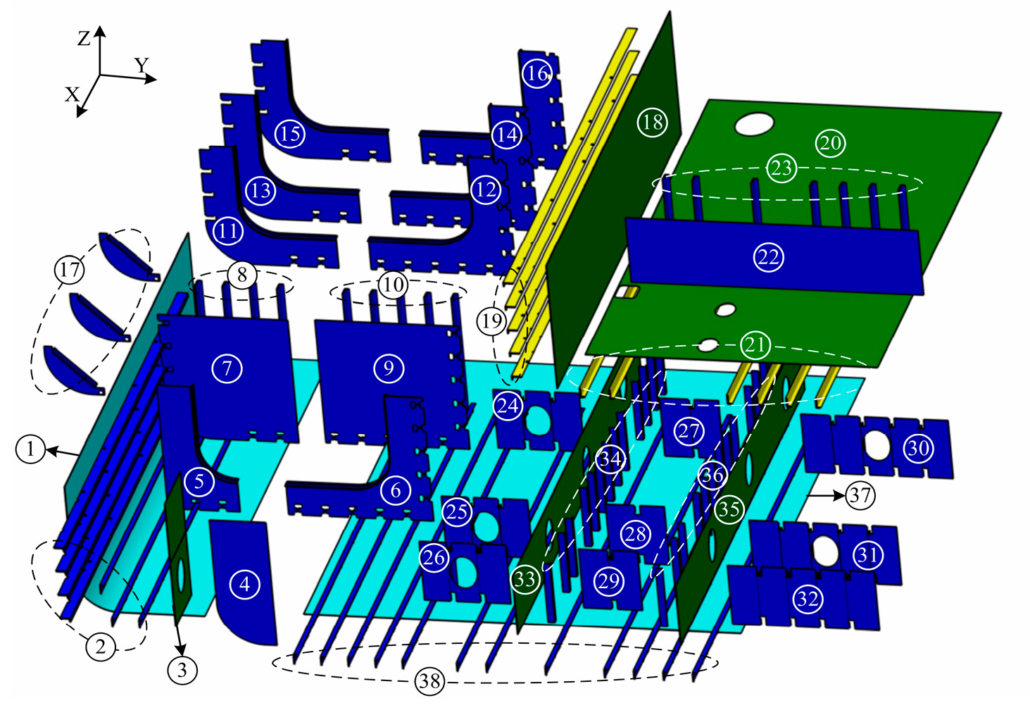
2.1. Data Extraction from CAD Model

The part data extraction aims to explore and make easy the use of the geometrical data of the part. In the Tribon system, the hull structure information is stored in an SB_OGDB database in hierarchical form. The Com-Object method is used to extract the relevant data of the part through multi-level keyword retrieval. According to the requirements of block subassembly partition, the data related to the plates, stiffeners, and cutouts are involved in this study. The data extraction process, as shown in Figure 2, involves extracting the weight and geometric features of all the panels and their sub-structures of a given block through traverse panels. Considering that the data of the panels and their sub-structures were provided in the local coordinate system (2D), it was necessary to complete the transformation of the extracted data based on the global coordinate system.
The extracted part data is stored in an Access database as the intermediate data for assembly relationship identification. Any geometrical handling on the part implies the processing of information indexed in the database. The form and relationships of the data table are shown in Figure 3. Level 1 is related to the block, which acts as an initial table for storing data and does not participate in the subsequent subassembly partition process; Level 2 is related to the panels, the main function of which is to transform the coordinate system and determine the subordinate relation of the sub-structures; Level 3 contains the information of the weight, position, and geometric features of the plates, stiffeners, and cutouts, according to which the connection and assembly interference between the parts can be deduced indirectly.

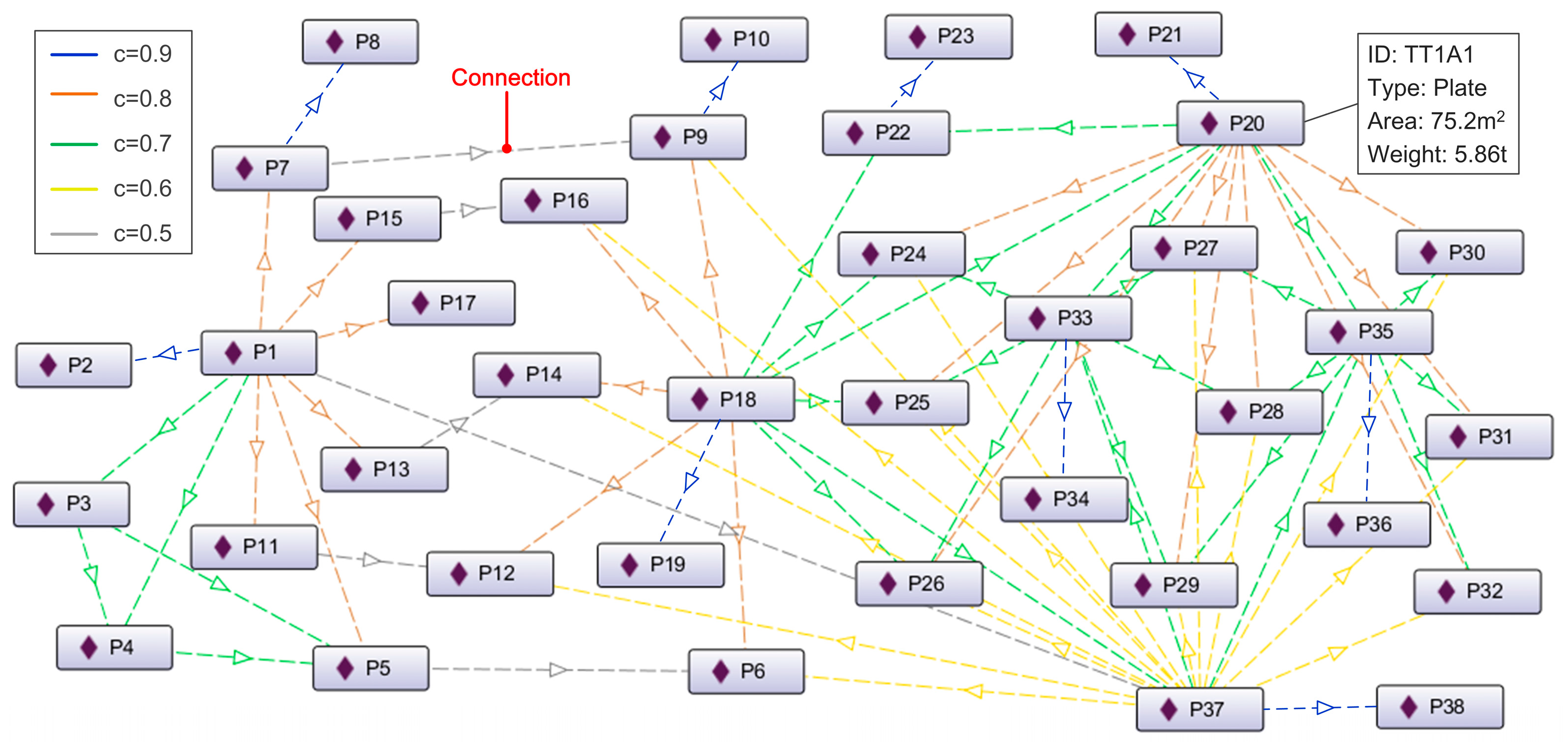
2.2. Connection Tightness

The connection relationship, defined as the contact and mating form between a pair of parts, is considered the main factor in determining the assembly priorities of parts. Different from other mechanical products, the integrity of the hull structure is ensured by permanent joints—welds [31]. The connection types will directly affect the contact stability between parts [32]. For the block structure, the connections can be classified into four common types: the fillet welding between the plate and stiffener; the fillet welding between plates where the weld is interrupted by the cutouts (including R-shaped cutouts and T-shaped cutouts); the fillet welding between plates with a continuous joint; and the butt welding between strakes [33]. Each welding type has its own technology, characteristics, and assembly requirements.
Considering that the parts within a flat block are distributed along the axis, the axis-aligned boundary box is selected to detect the connection relation of the parts, with the principle to detect the intersection of the projections of two boxes on three axes of X, Y, and Z. If the projections along any axis are separated, the two boxes are not connected; if the projections along any two axes are contiguous, then the boxes are in contact. Take the two plates in Figure 4 as an example. The corresponding boundary boxes can be regarded as the plates themselves. The contact is detected by comparing the value of the diagonal vertices coordinates of the boxes. After the contact detection, the connection type can be directly deduced according to the vertical direction of the plates. The connection detection between the stiffener and the plate is based on the same principle as above, except that the boundary box of the stiffener is created according to the insertion point coordinates and stiffener specifications.
Generally, the fillet welding between the stiffeners and plates has the highest priority because of the high stability of the structure and the limitation of the automatic welding conditions [34]. The fillet welding between a pair of plates with T-shaped cutouts has a higher requirement in the assembly path, as the plate can only be pulled into the target position along the vertical direction of the cutout when the stiffeners have been installed on the base plate, so the plates connected in this form should be assembled in priority to ensure the assembly feasibility. The assembly difficulty of fillet welding with a continuous joint is similar to that of fillet welding with R-shaped cutouts, but the former has higher welding efficiency and connection stability. The butt welding between strakes is usually performed at a later stage because the large size and weight of the structure make it difficult to lift and transport, which may require a higher capacity workstation or facilities to complete this task.
Through a comprehensive analysis of the part types and welding forms, as well as the characteristics of the assembly process, the quantitative and evaluation rules of contact tightness are formulated in this paper, as shown in Table 1.

2.3. Indirect Association

Generally, the welding relationships in the block are intricate due to the fact that there may be one-to-many connections among the parts, and such multiple welding relations will indirectly affect the assembly tightness between the parts. To evaluate this indirect relationship, this study presents the semantics of indirect association as a supplementary description of assembly tightness. For example, as shown in Figure 5, there is no contact between P4 and P5, but both are connected to P1 and P6, which increases the relationship tightness of them to some extent.
This relationship tightness described above is defined as the indirect association of the parts. Inspired by the method of determining the fuzzy similarity relation in fuzzy cluster analysis, the calculation method of indirect association is designed as follows:
a i j = k = 1 , k i , j n f ( c i k , c j k ) 10 k = 1 n ( c i k + c j k ) ,
f ( c i k , c j k ) = { max ( c i k , c j k ) , c i k 0 , c j k 0 0 , e l s e ,
where aij is the indirect association between part i and j; cij is the connection tightness between part i and j; and n is the total parts number of the product.
The indirect association is the further supplement for the assembly relation between parts on the basis of connection tightness, which improves the accuracy of assembly relation strength expression. In other words, the assembly relation strength between parts can be compared according to the indirect association when they have the same connected tightness.

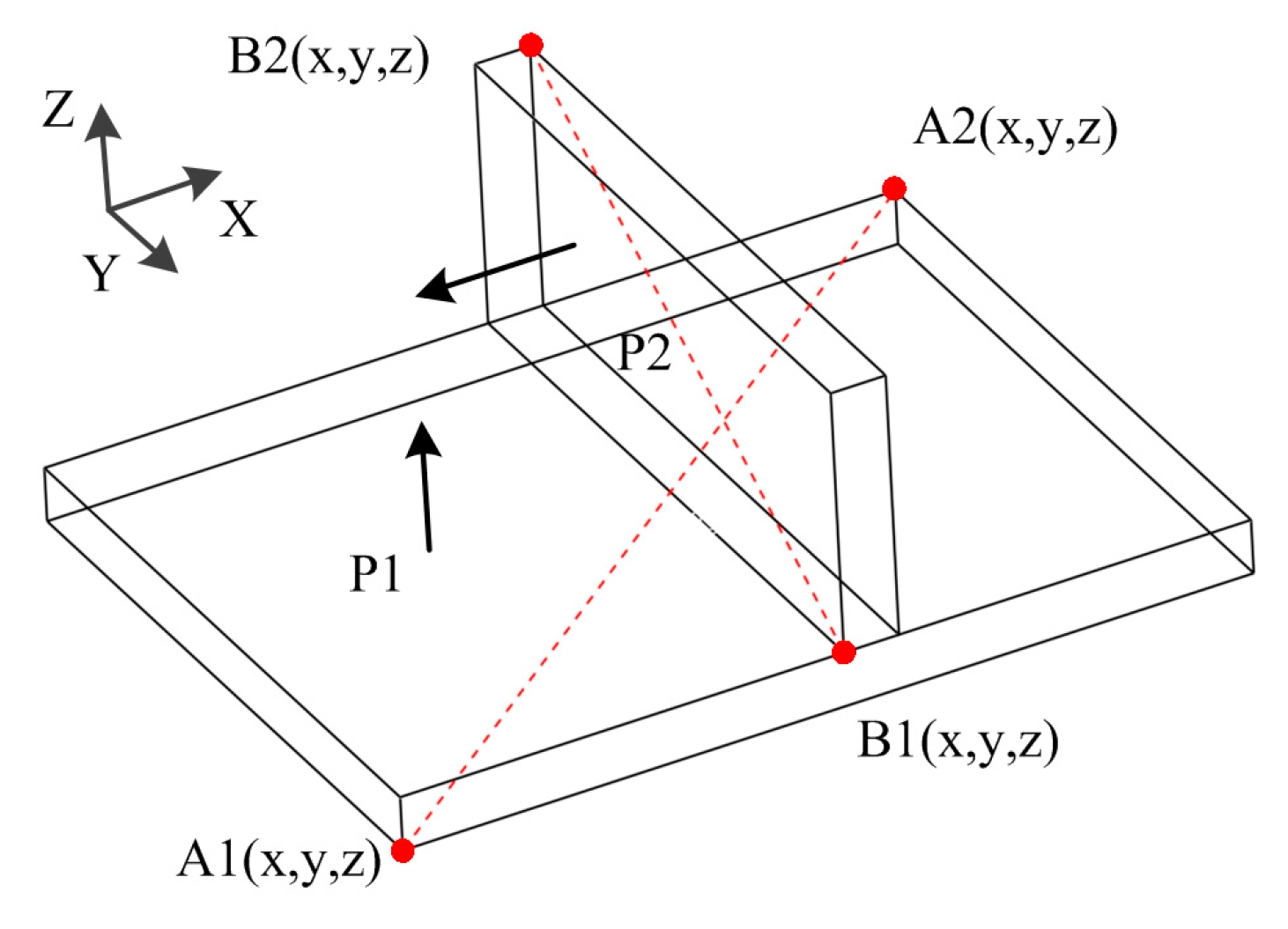
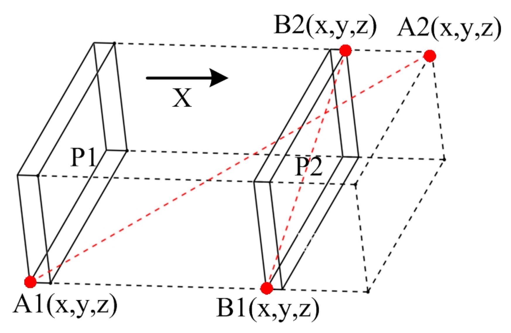
2.4. Interference Relation

The interference relation indicates the collision situation between parts when they are assembled or disassembled in a certain direction, which is the key basis to judge the assembly feasibility of parts in a three-dimensional space. Compared with other products’ typical mechanisms, the hull block is a so-called spares structure because its parts are distributed in the space in a more dispersed mode, and the block assembly is less sensitive to geometric constraints. Thus, in this paper, the assembly path is assumed to be confined to the principal axis.
The principle of assembly interference detection is similar to that of contact detection. The difference is that assembly interference detection needs to create a new boundary box by stretching the moving part along the assembly direction for a certain distance, as shown in Figure 6. The assembly interference can be determined by detecting the intersection of the projections of the new box and another fixed part. In the case of the stiffener through the plate, the boundary boxes are always intersecting, and the assembly interference relationship can be determined according to the cutout type at the corresponding position of the plate.
Equation (3) shows the interference relation matrix of the parts assembly.
I M = [ I ( i , j , k ) ] n × n × 6 ,
where k represents the assembly direction, and it is defined as (+x, +y, +z, −x, −y, −z); I(i, j, k), which means that if part i collides with part j when it is assembled along direction k, then I(i, j, k) = 1, or else, I(i, j, k) = 0.

3. Optimization Model for SP

Varied subassembly partition criteria exist in different industries, each of which encompasses a series of unique principles. In this study, with a focus on block construction, five principles are defined as follows according to the characteristics of the assembly process and techniques.
Principle 1: There should be at least one plate in each subassembly as the base part for assembly.
Principle 2: Each part in the subassembly is connected at least with one of the other parts in the subassembly.
Principle 3: It is feasible in the assembly direction when the subassembly is assembled as a whole.
Principle 4: The weight and size of the subassembly should be within the capacity of the workstation.
Principle 5: Subassemblies should have good stability and rigidity to facilitate transportation and lifting.
The first four principles are the rigid constraints and necessary conditions for the subassembly. If these principles cannot be met at the same time, the generated subassembly does not agree with the manufacturing reality. Therefore, this research designed these principles as the corresponding constraints for the optimization, which are as follows:
s . t { s i S , p j i s i ,     p j   i s   a   p l a t e ; s i S , p j i s i , k = 1 , k j n i c k j > 0 ; s i , s j S , k = 1 6 I ( s i , s j , k ) < 6 ; s i S , W s i W max ; ,
where S is the set of subassemblies; si is the set of members in subassembly i; Wsi is the weight of subassembly I; and Wmax is the maximum allowable weight of the assembly station.
For the fifth principle, subassembly stability means that the inner parts cannot deviate and deform from the subassembly when moving and lifting the subassembly as a whole. Subassembly stability is a relatively flexible but important indicator because of its significant impact on assembly difficulty and efficiency. In this research, subassembly cohesion is used to evaluate the subassembly stability, and it is directly proportional to the connection compactness of the inner parts. Therefore, the optimization objective in this paper is to achieve the highest cohesion within subassemblies under the premise of a reasonable cluster number. The objective function is designed as follows:
F = 1 m i = 1 m C O i ,
where F is the fitness value of the solution, and the purpose is to find the solution with the maximum fitness value; m is the number of subassemblies partitioned in the solution; and COi is the cohesion within subassembly i, which is used to evaluate the compactness of the parts within the subassembly. The calculation of COi is designed as follows:
C O i = α n i 1 j = 1 , j b n i ( c j b ( i ) + a j b ( i ) ) + 2 ( 1 α ) n i ( n i 1 ) j = 1 n i k = j + 1 n i ( c j k ( i ) + a j k ( i ) ) ,
where α is the weight coefficient and b is the index of the basis part in the subassembly. The first half of the equation represents the assembly cohesion of the base plate with other parts, while the second half represents the cohesion of all the parts to one other. In block building, the base plate plays a key role, which is connected to a great number of other parts and supports nearly all the other parts in the subassembly. Compared with the assembly cohesion between parts, the cohesion of the base plate with others has a more critical influence on the structural stability of the subassembly. Therefore, it is considered reasonable to choose 0.7 as the weight coefficient for the cohesion calculation of the subassembly.
q j ( i ) = A j ( i ) A max ( i ) A min ( i ) + N j ( i ) N max ( i ) N min ( i ) ,
where Aj(i) is the area of part j from subassembly I, and Nj(i) is the number of elements that are connected to part j.

4. PSO-Based Method Design

The PSO algorithm is one of the intelligent swarm algorithms, inspired by the predation behavior of birds. The PSO algorithm is one of the intelligent swarm algorithms, inspired by the predation behavior of birds. The basic principle of the PSO algorithm is to search the optimal particle position through the movement of particles using the information-sharing mechanism between individuals. Basically, with a strong local and global search ability and high convergence efficiency, the PSO algorithm is considered simple-structured, easily implemented, and executable, with fewer parameters to be adjusted, compared with other bionic algorithms. In addition, the discrete PSO algorithm has the ability to deal with combinatorial optimization problems. In terms of the above advantages, the PSO algorithm has been widely used in solving ASP problems [35], and its efficiency in tackling ASP has been improved to some extent. However, traditional PSO algorithms, confined to solving serial ASP—a one-by-one task to finish the assembly process, bear great difficulty in solving the subassembly detection problem due to its fuzzy and parallel nature [29]. Upon consideration of the identified research gaps, a two-dimensional PSO algorithm is proposed, and the coding and iteration methods are introduced in the following sections.

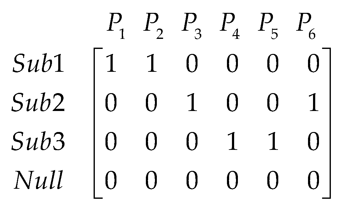
4.1. Position and Velocity of the Particle

The particle position is defined as a scheme of subassembly partition. Considering that a one-dimensional vector is insufficient to describe the problem, an example of a Boolean matrix is designed as follows:
X i = [ x 11 x 12 x 1 n x 21 x 22 x 2 n x n 1 x n 2 x n n ] ,
where the row of the matrix represents a subassembly unit, and the column is the index of the part; xjk means that if part k belongs to subassembly j then xjk = 1, or else xjk = 0. For a column, only one element is 1, and the rest are 0.
As shown in Figure 7, the example particle indicates that the product is divided into three subassemblies, which are SuA1: {P1, P2}, SuA2: {P3, P6}, and SuA3: {P4, P5}.
Similarly, particle velocity is defined as the change in the particle position, which means an adjustment to the SP scheme. Equation (9) shows the encoding of the particle velocity.
V i = [ v 11 v 12 v 1 n v 21 v 22 v 2 n v n 1 v n 2 v n n ] ,
where the row of the matrix has the same meaning as the position matrix, while the column is the grouping adjustment of the corresponding part. For each column of the matrix, at most one element has a value of 1, and the rest are 0.

4.2. Addition Operator of PSO

Suppose that X = [x1, x2, …, xk, …, xn] and V = [v1, v2, …, vk, …, vn] are the position and velocity of the particle, then the addition operator is defined as shown in Equations (10) and (11), and the operation example is shown in Figure 8a.
X = X + V ,
x = { v j , v j 0 x j , v j = 0 ,
where X′ is a new position of the particle; xj and vj are the j-th column vector of the position matrix and velocity matrix, respectively. If vj is the zero vector or the same as xj, then the vector x′j inherits from xj. Otherwise, x′j is replaced by vj.
The velocity addition is used to obtain the superposed effect of velocities. Suppose there are two velocities: V1 = [v11, v12, …, v1k, …, v1n] and V2 = [v21, v22, …, v2k, …, v2n]. Then, the addition of velocities is defined as shown in Equations (12) and (13).
V 1 = V 2 + V 3 ,
v 3 j = { v 1 j , v 1 j = v 2 j v 1 j , v 1 j v 2 j ,   r 0.5 v 2 j , v 1 j v 2 j ,   r < 0.5 ,
where V3 is the new velocity, v3j is the j-th column vector of V3, and r is the random number between 0 and 1. Normally, the more random numbers, r, between 0 and 0.5, the more elements in the velocity matrix, V3, are inherited from V2, or else, the more elements are inherited from V1. The example is shown in Figure 8b, where r1 and r3 represent the generated random number during the operations of the first and third column vectors, respectively.

4.3. Subtraction Operator of PSO

The subtraction between two particle positions will generate a new particle velocity. Suppose the two positions are X1 = [x11, x12, …, x1k, …, x1n] and X2 = [x21, x22, …, x2k, …, x2n], the subtraction of the two particles is defined as follows, and the example is shown in Figure 8c.
V = X 2 X 1 ,
v j = { 0 , x 1 j = x 2 j x 2 j , x 1 j x 2 j ,

4.4. Multiplication Operator of PSO

Equations (16) and (17) show the designed multiplication operator of PSO.
V 2 = c V 1 ,
v 2 j = { v 1 j , r < c 0 , r c ,
where c is the control parameter, which controls the degree of the column vector inherited from V1, and r is a random number evenly distributed between 0 and 1. It can be inferred from the above formula that the bigger the value of c, the more column vectors will be inherited from V1. The example is shown in Figure 8d, where r1, r2, and r3 represent the random number generated during the multiplicative operations through 1 to 3 column vectors, respectively.

4.5. Iterative Update of PSO

Based on the special definition of the position, velocity, and operations of the particle, the iterative update operator of the particles is designed as shown in Equations (18) and (19) according to the standard PSO algorithm [24].
V i ( t + 1 ) = ω V i ( t ) + c 1 [ P i X i ( t ) ] + c 2 [ P g X i ( t ) ] ,
X i ( t + 1 ) = X i ( t ) + V i ( t + 1 ) ,
where t is the current iteration number of the algorithm; Pi represents the personal historical best position of the particle i and Pg is the global historical best position of the particle swarm; ω is inertia weight, which holds the motion inertia of the particle swarm and provides the particle swarm with the tendency to expand the search space; and c1 and c2 are learning factors that adjust the effect of the individual position and swarm position on the particle motion. The coefficients of the inertia weight and learning factors are defined as variables and are calculated as follows [27]:
ω = ω min + ω max ω min G max × t ,
c 1 = c 1 min + c 1 max c 1 min G max × t ,
c 2 = c 2 max c 2 max c 2 min G max × t ,
where Gmax is the maximum iteration number, while t denotes the current iteration number, and ωmax, ωmin, c1max, c1min, c2max, and c2min are the maximum and minimum values of each coefficient, respectively. The purpose of the above formula is to ensure the diversity of the population in the early stage and accelerate the convergence of the population in the last stage of the algorithm. After repeated tests, the relevant constant parameters in this study are preset as ωmax = 0.9, ωmin = 0.1, c1max = 0.8, c1min = 0.2, c2max = 0.8, and c2min = 0.2.

5. Cases Study and Discussion
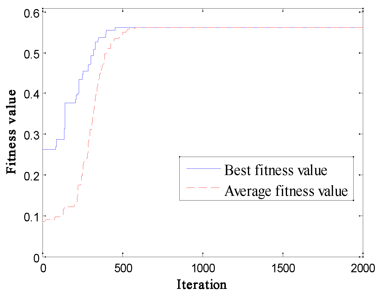
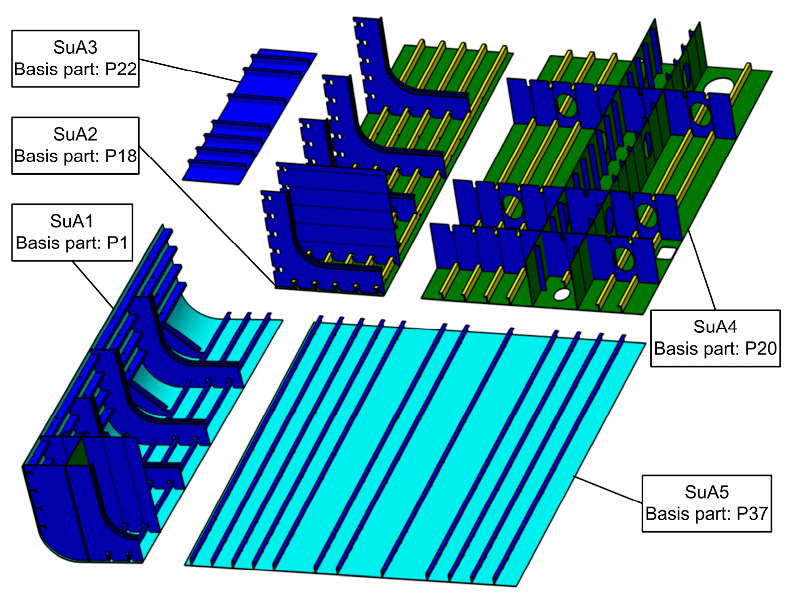
5.1. Case 1

Case 1 is a hopper unit block of a bulk carrier from the literature [18], and the model is shown in Figure 9. To compress the size of the solution matrix, the same link can be simplified using the synthetic expression method, and the connection tightness matrix is shown in Figure 10.
The proposed two-dimensional PSO algorithm is applied in this case, and the initial parameters are set as follows: the maximum iterations Gmax = 500, the population size P = 50, and the maximum number of subassemblies mmax = 5. The convergence curve of the objective function obtained is illustrated in Figure 11, from which the maximum value of the evaluation function reaches 6.176. Correspondingly, the obtained optimal solution is {SuA1: DP1, FZ1}; {SuA2: DP2, FZ2, TB4}; {SuA3: TB1, FZ3}; {SuA4: TB2, FZ4}; and {SuA5: TB3, FZ5}. The outcome is confirmed to be consistent with that reported in the literature, which proves that the proposed method is feasible for the block assembly.

5.2. Case 2

To verify the applicability of the method to a complex product, a double-bottom block of an ocean engineering vehicle, as shown in Figure 12, is selected in Case 2. Figure 13 introduces the block structure and the distribution of the parts. To compress the size of the solution matrix, the similar parts are uniformly pre-combined and numbered. The connection details of the parts are shown in Figure 14.
On this basis, the proposed PSO algorithm is applied in the case and the initial parameters are set as the maximum iterations Gmax = 2000, the population size P = 50, and the maximum number of subassemblies mmax = 7. The calculation process is illustrated in Figure 15, from which the maximum value of the objective function reaches 0.563. The optimal solution is as follows:
SuA1: {P1~P8, P11, P13, P15, P17}; SuA2: {P6, P9, P10, P12, P14, P16, P18, P19}; SuA3: {P22, P23}; SuA4: {P20, P21, P24~P36}; and SuA5: {P37, P38}. Moreover, P1, P18, P22, P20, and P37 serve as the base plate in the corresponding subassemblies. The diagram of the obtained solution is shown in Figure 16. After confirmation, the obtained solution is in agreement with that designed by the shipyard engineers.
For the obtained solution, the generated subassemblies can be assembled conveniently in the smaller building stations to reduce the spatial difficulty of the parts assembly and increase the area of the assembly operation. Then, all the built subassemblies are transferred to a larger platform for further assembly, in which the turnover rate of the large capacity assembly station is improved. In addition, the generated solution changes most welding work from over-head to down-head to simplify the welding work and minimize the work period.

5.3. Discussion

The subassembly recognition approach based on the PSO algorithm first requires the initialization of main factor parameters, thereby imposing a significant impact on the recognition method in achieving the objective function optimization and generating reasonable recognition results. The main factors involved in the recognition process are the population size, the maximum iterations, and the quantity range of the subassemblies. As the parts number increases, the convergence rate of the algorithm decreases, which requires more iterations to search for the optimal solution. Therefore, the pre-combination of parts with the same properties before the subassembly partition can greatly improve the computational efficiency of the algorithm.
Theoretically, the heuristic algorithm-based subassembly partition method proves to be applicable in obtaining the optimal solution, but the difficulty lies in setting a reasonable evaluation function and relevant constraints. Products from different industries are subjected to different standards, objectives, and constraints in generating subassemblies. In shipbuilding, weight restrictions, stability requirements, and the feasibility of the assembly path are the major considerations for subassembly partition technology.

6. Conclusions and Future Work

In terms of the subassembly partition for the ship block structure, an automated approach is proposed based on a two-dimensional PSO algorithm. The advantages of the developed approach can be revealed as follows: first, the application interface program can be used to extract the required product assembly information from the CAD system, which reduces human participation and improves the automatic degree in the subassembly partition process; second, the connection tightness and indirect association, which are newly raised concepts in the approach, improve the expression rationality of the assembly relation between the parts; and third, the designed two-dimensional coding method can enable the PSO algorithm to be more applicable in solving discrete fuzzy clustering optimization problems, especially in realizing subassembly partition.
However, some limitations still exist in the proposed approach. First, the proposed approach is based on the assumption that parts can only be assembled along the axis. For blocks with large curvature and an irregular structure, assembly directions outside the axis need to be considered. Second, as the part number increases, the convergence rate of the method slows down, and more iterations and computing time to search for the optimal solution are required.
In fact, it proves unrealistic to have a single subassembly partition scheme due to several reasons. First, there is no uniform standard and criteria among various methods to evaluate the generated subassemblies. Second, for complex products, subassembly division may contain several levels assimilating a tree structure, so subassemblies generated at various levels are different. Third, different assembly constraints are considered for products in various industries or of different structure types. Fourth, the evaluation of the assembly relation between parts has a great influence on the computing results. Fifth, the production conditions and the assembly capacity impose a great impact on the subassembly partition process.
Consequently, our future work will focus on the study of the assembly constraints of block building and the evaluation criteria of subassembly division based on the actual construction conditions and the assembly capacity of the shipyard and the improvement of the proposed algorithm with a combination of other heuristic algorithms or theories, such as a tabu search, neighborhood search, genetic algorithm, immune algorithm, etc., to improve the convergence speed of the algorithm and its ability to search for optimal solutions.

Author Contributions

Methodology, B.L.; investigation, Y.L. and J.W.; software, B.L. and R.L.; data support, R.L.; supervision, S.L.; writing—original draft preparation, B.L; resources, Y.L. and J.W. All authors have read and agreed to the published version of the manuscript.

Funding

This study was financially supported in part by the National Natural Science Foundation of China (Grant No. 51979034) and in part by the Science and Technology Innovation Foundation of Dalian (Grant No. 2021JJ12GX025).

Institutional Review Board Statement

Not applicable.

Informed Consent Statement

Not applicable.

Data Availability Statement

All the data are contained within the article.

Conflicts of Interest

The authors declare no conflict of interest.

References

  1. Jeong, D.; Kim, D.; Choi, T.; Seo, Y. A Process-Based Modeling Method for Describing Production Processes of Ship Block Assembly Planning. Processes 2020, 8, 880. [Google Scholar] [CrossRef]
  2. Qu, S.; Jiang, Z.; Tao, N. An integrated method for block assembly sequence planning in shipbuilding. Int. J. Adv. Manuf. Technol. 2013, 69, 1123–1135. [Google Scholar] [CrossRef]
  3. Kang, M.; Seo, J.; Chung, H. Ship block assembly sequence planning considering productivity and welding deformation. Int. J. Nav. Archit. Ocean. Eng. 2018, 10, 450–457. [Google Scholar] [CrossRef]
  4. Wang, W.; Chen, G.; Lin, Z.; Lai, X. Automated Hierarchical Assembly System Construction in Automobile Body Assembly Planning. J. Mech. Des. 2005, 127, 347–351. [Google Scholar] [CrossRef]
  5. Cao, H.; Mo, R.; Wan, N.; Shang, F.; Li, C.; Zhang, D. A subassembly identification method for truss structures manufacturing based on community detection. Assem. Autom. 2015, 35, 249–258. [Google Scholar] [CrossRef]
  6. Seo, Y.; Sheen, D.; Kim, T. Block assembly planning in shipbuilding using case-based reasoning. Expert Syst. Appl. 2007, 32, 245–253. [Google Scholar] [CrossRef]
  7. Li, C.; Hou, W.; Jafari Navimipour, N. Assembly Sequence Planning Based on Hierarchical Model. Wirel. Commun. Mob. Comput. 2022, 2022, 9461794. [Google Scholar] [CrossRef]
  8. Bahubalendruni, M.V.A.R.; Biswal, B.B. A review on assembly sequence generation and its automation. Proc. Inst. Mech. Eng. Part C J. Mech. Eng. Sci. 2015, 230, 824–838. [Google Scholar] [CrossRef]
  9. Xing, Y.; Karjalainen, I.; Chen, G.; Lai, X.; Jin, S.; Zhou, J. Assembly sequence planning of automobile body components based on liaison graph. Assem. Autom. 2007, 27, 157–164. [Google Scholar] [CrossRef]
  10. Wang, Y.; Tian, D. A weighted assembly precedence graph for assembly sequence planning. Int. J. Adv. Manuf. Technol. 2015, 83, 99–115. [Google Scholar] [CrossRef]
  11. Wang, Y.; Liu, J. Subassembly identification for assembly sequence planning. Int. J. Adv. Manuf. Technol. 2013, 68, 781–793. [Google Scholar] [CrossRef]
  12. Homem de Mello, L.S.; Sanderson, A.C. A correct and complete algorithm for the generation of mechanical assembly sequences. IEEE Trans. Robot. Autom. 1991, 7, 228–240. [Google Scholar] [CrossRef]
  13. Fan, J.; Ye, Y.; Cai, J.M. Multi-level intelligent assembly sequence planning algorithm supporting virtual assembly. In Proceedings of the IEEE International Conference on Systems, Man, and Cybernetics (SMC), Hague, The Netherlands, 10–13 October 2004; pp. 3494–3499. [Google Scholar]
  14. Li, Y.; Chu, X.; Chu, D.; Liu, Q. An integrated module partition approach for complex products and systems based on weighted complex networks. Int. J. Prod. Res. 2014, 52, 4608–4622. [Google Scholar] [CrossRef]
  15. Trigui, M.; Belhadj, I.; Benamara, A. Disassembly plan approach based on subassembly concept. Int. J. Adv. Manuf. Technol. 2016, 90, 219–231. [Google Scholar] [CrossRef]
  16. Gulivindala, A.K.; Bahubalendruni, M.R.; Varupala, S.V.P. A heuristic method with a novel stability concept to perform parallel assembly sequence planning by subassembly detection. Assem. Autom. 2020, 40, 779–787. [Google Scholar] [CrossRef]
  17. Liu, B.; Li, R.; Wang, J.; Liu, Y.; Li, S. Assembly Unit Partition Method for Ship Block based on Assembly Relationship. J. Huazhong Univ. Sci. Technol. 2019, 47, 118–123. [Google Scholar]
  18. Zhong, Y.; Xue, K.; Shi, D. Assembly unit partitioning for hull structure in shipbuilding. Comput.-Aided Des. 2013, 45, 1630–1638. [Google Scholar] [CrossRef]
  19. Kou, X.; Cao, Y.; Wang, Q.; Qiao, H. Sub-assembly recognition algorithm and performance analysis in assembly sequence planning. Int. J. Adv. Manuf. Technol. 2019, 107, 971–981. [Google Scholar] [CrossRef]
  20. Zhang, C.; Zhou, G.; Lu, Q.; Chang, F. Generating significant subassemblies from 3D assembly models for design reuse. Int. J. Prod. Res. 2018, 56, 4744–4761. [Google Scholar] [CrossRef]
  21. Qiao, L.; Qie, Y.; Zhu, Z.; Zhu, Y.; Zaman, U.K.U.; Anwer, N. An ontology-based modelling and reasoning framework for assembly sequence planning. Int. J. Adv. Manuf. Technol. 2018, 94, 4187–4197. [Google Scholar] [CrossRef]
  22. Shi, X.; Tian, X.; Wang, G.; Zhao, D.; Zhang, M. Semantic-based subassembly identification considering non-geometric structure attributes and assembly process factors. Int. J. Adv. Manuf. Technol. 2020, 110, 439–455. [Google Scholar] [CrossRef]
  23. Zhang, L.; Lv, H.; Tan, D.; Xu, F.; Chen, J.; Bao, G.; Cai, S. Adaptive quantum genetic algorithm for task sequence planning of complex assembly systems. Electron. Lett. 2018, 54, 870–871. [Google Scholar] [CrossRef]
  24. Li, M.; Wu, B.; Hu, Y.; Jin, C.; Shi, T. A hybrid assembly sequence planning approach based on discrete particle swarm optimization and evolutionary direction operation. Int. J. Adv. Manuf. Technol. 2013, 68, 617–630. [Google Scholar] [CrossRef]
  25. Ab Rashid, M.F.F. A hybrid Ant-Wolf Algorithm to optimize assembly sequence planning problem. Assem. Autom. 2017, 37, 238–248. [Google Scholar] [CrossRef]
  26. Li, X.; Qin, K.; Zeng, B.; Gao, L.; Su, J. Assembly sequence planning based on an improved harmony search algorithm. Int. J. Adv. Manuf. Technol. 2015, 84, 2367–2380. [Google Scholar] [CrossRef]
  27. Li, M.; Wu, B.; Yi, P.; Jin, C.; Hu, Y.; Shi, T. An improved discrete particle swarm optimization algorithm for high-speed trains assembly sequence planning. Assem. Autom. 2013, 33, 360–373. [Google Scholar] [CrossRef]
  28. Yang, Y.; Yang, M.; Shu, L.; Li, S.; Liu, Z. A Novel Parallel Assembly Sequence Planning Method for Complex Products Based on PSOBC. Math. Probl. Eng. 2020, 2020, 7848329. [Google Scholar] [CrossRef]
  29. Taraska, M.; Iwankowicz, R.; Urbanski, T.; Graczyk, T. Review of Assembly Sequence Planning Methods in terms of Their Applicability in Shipbuilding Processes. Pol. Marit. Res. 2018, 25, 124–133. [Google Scholar] [CrossRef]
  30. Tang, J.; Tian, X.; Geng, J. Integrated precision information model of model-based definition. Comput. Integr. Manuf. Syst. 2014, 20, 1827–1833. [Google Scholar]
  31. Li, S.; Tang, D.; Xue, D.; Wang, Q.; Zhu, H. Assembly sequence planning based on structure cells in open design. Adv. Eng. Inform. 2022, 53, 101685. [Google Scholar] [CrossRef]
  32. Wu, Z.; Du, J.; Zhu, M.; Fan, X. Survey on Flexible Shipbuilding Technologies for Curved Ship-Blocks. Procedia Eng. 2017, 174, 800–807. [Google Scholar]
  33. Iwankowicz, R.R. An efficient evolutionary method of assembly sequence planning for shipbuilding industry. Assem. Autom. 2016, 36, 60–71. [Google Scholar] [CrossRef]
  34. Lei, L.; Di, L.; Pengyu, W.; Honggen, Z. Research on Hull Assembly Process Planning Based on Rule Reasoning. In Proceedings of the 5th International Conference on Mechanical and Aeronautical Engineering (ICMAE), Sanya, China, 12–15 December 2019; p. 012084. [Google Scholar]
  35. Wang, Y.; Liu, J.H. Chaotic particle swarm optimization for assembly sequence planning. Robot. Comput.-Integr. Manuf. 2010, 26, 212–222. [Google Scholar] [CrossRef]
Figure 1. Strategy of the proposed method.
Jmse 11 01006 g001
Figure 2. Data extraction process.
Jmse 11 01006 g002
Figure 3. Intermediate database structure.
Jmse 11 01006 g003
Figure 4. Connected relation identification.
Jmse 11 01006 g004
Figure 5. The example of a sample structure diagram.
Jmse 11 01006 g005
Figure 6. Assembly interference detection.
Jmse 11 01006 g006
Figure 7. Example of the particle position.
Jmse 11 01006 g007
Figure 8. The example of the designed operators of PSO algorithm: (a) The example of position update; (b) The example of velocity addition; (c) The example of position subtraction; (d) The example of multiplication.
Jmse 11 01006 g008
Figure 9. Structure diagram of the block.
Jmse 11 01006 g009
Figure 10. Connection tightness of the block.
Jmse 11 01006 g010
Figure 11. Convergence curve of the optimization.
Jmse 11 01006 g011
Figure 12. CAD model of the block.
Jmse 11 01006 g012
Figure 13. Structure and parts number of the block.
Jmse 11 01006 g013
Figure 14. Connected relations of the block.
Jmse 11 01006 g014
Figure 15. Convergence curve of the algorithm.
Jmse 11 01006 g015
Figure 16. The diagram of the optimal solution.
Jmse 11 01006 g016
Table 1. Rules for determining the connection tightness.
IndexContact ModeTightnessDiagram
Rule 1pi is a plate, pj is a stiffener, and the contact is face-to-edge.cij = 0.9Jmse 11 01006 i001
Rule 2Both pi and pj are plates, and the contact is face-to-edge and the joint is interrupted with a T-shaped cutout.cij = 0.8Jmse 11 01006 i002
Rule 3Both pi and pj are plates, and the contact is face-to-edge and the joint is straight and continuous.cij = 0.7Jmse 11 01006 i003
Rule 4Both pi and pj are plates, and the contact is face-to-edge and the joint is interrupted with an R-shaped cutout.cij = 0.6Jmse 11 01006 i004
Rule 5Both pi and pj are strakes, and the contact is edge-to-edge.cij = 0.5Jmse 11 01006 i005
Disclaimer/Publisher’s Note: The statements, opinions and data contained in all publications are solely those of the individual author(s) and contributor(s) and not of MDPI and/or the editor(s). MDPI and/or the editor(s) disclaim responsibility for any injury to people or property resulting from any ideas, methods, instructions or products referred to in the content.

