Article

An All-Electric Gate Valve Actuator for Subsea Production Control Systems, Part A: Prototype and Test

1
Guangzhou Panyu Polytechnic, Guangzhou 511483, China
2
College of Mechanical and Electrical Engineering, Harbin Engineering University, Harbin 150001, China
3
Guangdong Mechanical and Electronical College of Technology, Guangzhou 510515, China
*
Author to whom correspondence should be addressed.
J. Mar. Sci. Eng. 2023, 11(5), 1043; https://doi.org/10.3390/jmse11051043
Submission received: 17 April 2023 / Revised: 9 May 2023 / Accepted: 12 May 2023 / Published: 13 May 2023
(This article belongs to the Section Ocean Engineering)

Abstract

:
To bridge the gap that exists in the key equipment of the new subsea production control system, the all-electric subsea gate valve actuator, and exploit subsea oil and gas resources with high reliability and safety while saving energy, this paper proposes a novel concept prototype of an all-electric subsea gate valve actuator which has the key functions of a redundant drive, failsafe closing, auxiliary override, position indication, and low-power position holding. It satisfied the electrically-driven requirements of the subsea gate valves and achieved Safety Integrity Level 3. The prototype was developed and tested successfully. The all-electric subsea gate valve actuator is suitable for controlling subsea gate valves with various sizes and rated working pressures to minimize the power consumption for the purpose of keeping the valves open and safely closing them in the event of the electrical failure. An override and position-indicating mechanism is equipped for emergency operation and the visual indication of the status of subsea gate valves.

1. Introduction

Subsea production control systems are widely used for developing deepwater oil and gas resources due to their advantages [1]. At present, a multiple electric–hydraulic control system (MEH) based on hydraulic drive technology is still a traditional method [2]. However, with the discovery and development of oil and gas resources in challenging areas, such as ultra-deep waters, ultra-long step-outs, complex well technologies, and challenging weather conditions, MEH systems are not able to meet the control requirements of certain fields due to their inherent performance limitations [3,4,5]. The all-electric subsea production control system (AE), a leading-edge and breakthrough technology, was proposed and developed [6], which was driven completely by electric power. The AE system became a development direction due to its advantages in the areas of operation and maintenance costs, control performance, and environmental friendliness [7,8,9,10].
The all-electric subsea gate valve actuator is the most critical component in the AE system, used to control the on–off, flow, and pressure control of production media such as oil, gas, and chemicals. It directly affects the operation of the AE system [11]. Several oil companies have carried out relevant research on this topic. Cameron’s all-electric subsea gate valve actuator was powered by a “drive” motor and a “clutch” motor, and a closing spring was used as the failsafe close solution. The “drive” motor was responsible for opening and closing the valve and the “clutch” motor was used to ensure that the valve remained open [12,13]. Aker Solutions proposed all-electric subsea gate valve actuators of high and low types, consisting of battery modules, power supply modules, communication and control modules, and drive motors. Each component of the actuator was designed with dual redundancy. In addition, a remotely operated vehicles (ROV) interface and multi-level gear transmission mechanisms were equipped [14]. TechnipFMC’s all-electric subsea gate valve actuators featured precise control of the valve position and torque, vibration monitoring, ROV installation, and variable maximum torque and speed ranges. A battery management system was equipped to utilize subsea rechargeable batteries and local power storage for the power supply. In addition, no springs were required for the failsafe closing, resulting in the compact and lightweight design of the actuators [15,16]. Rexroth Bosch Group presented the world’s first all-electric subsea gate valve actuator to replace conventional hydraulic cylinders without taking up any additional space. The actuator contained an electric drive, a motion control system, a safety device, and a pressure-compensated container. It required only one cable for the power supply and communication, and was equipped with a standard ROV interface [17,18]. OneSubsea’s all-electric subsea gate valve actuators were mainly composed of the motor control unit, motor, and gearbox, where the motor control unit adapted the motor current and frequency for the purpose of adjusting the motor speed to the actual torque. In addition, the standard ROV interface was equipped with a spring-mounted shaft [19,20].
In addition to the deepwater equipment suppliers mentioned above, researchers conducted a series of studies on all-electric subsea gate valve actuators as well. Winther-Larssen [21] specified functional design specifications for all-electric subsea gate valve actuators and proposed a drive system layout. Berven [22] analyzed the failsafe solution and the load of the all-electric subsea gate valve actuator. Wang [23] concluded that the multi-motor parallel redundant drive was more suitable for all-electric subsea gate valve actuators. Xiao [24] presented an all-electric subsea gate valve actuator scheme for the Christmas tree and analyzed the sealing process of the gate valve. Liu [25] developed a pressure compensation all-electric control gate valve and actuator-integrated structure, which substantially reduced the high-pressure hydraulic resistance during the valve closing process. In addition, Liu [26] conducted a simulation analysis for the flow channel in the hydraulic section of the integrated actuator structure and obtained the optimal model for the hydraulic side of the valve and actuator. Tian [27] proposed a high-dynamic-speed control strategy for subsea electrical actuators, which remarkably improved the system’s dynamics. Alexandre [28] presented the development and qualification of a novel subsea electric actuator for rotary small-bore valves, which included a field-proven spring and the electric drive and controls. Liu [29] developed a redundant control system of an all-electric actuator and proposed a two-layer synchronous control strategy of an integrated condition detection module. Glenn-Roar [30] explained the business case for the electric subsea valve operation solution and highlighted the experiences from the operation of the system. Carsten [31] pointed out that, so far, there were no standardized generic requirements documented for electrical actuators, and proposed the development of a qualification program for subsea all-electric actuators. Alexandre [32] provided a comparison of the design strategies using mechanical springs or electric batteries to implement safety functions in control systems, considering the development of the new subsea electric actuator for small-bore valves SVA R2 from Bosch Rexroth as a case study. Markus [33] investigated the potential effects which could be measured after saltwater entered the Christmas Tree actuators and proposed a sensor design for industrialization.
The all-electric subsea gate valve actuator is a type of highly integrated electromechanical equipment. At present, all-electric actuators of oil companies are still in the experimental stage, and key technologies are still immature. Most of the all-electric subsea gate valve actuators proposed by scholars and researchers only concentrate on the changes in the drive and transmission mechanisms caused by changes in the driving method, ignoring the realization of other functions of the all-electric subsea gate valve actuator. This present work is aimed at developing a novel and feasible concept prototype of an all-electric subsea gate valve actuator and carrying out the related test, which is intended to satisfy the electrically-driven requirements of subsea gate valves and has key functions including the redundant drive, failsafe closing, auxiliary override, position indication, and low-power position holding. It also achieves Safety Integrity Level SIL 3, bridging the gap that exists in the key equipment of the new subsea production control system.

2. Design of the All-Electric Subsea Gate Valve Actuator

Subsea gate valve actuators can be classified into manual, hydraulic, and electric types, according to the driving method. The hydraulic subsea gate valve actuator driven by hydraulic power is the mainstream at present, and the all-electric control subsea gate valve actuator is the trend in applications.
Compared with the hydraulic subsea gate valve actuator, the all-electric subsea gate valve actuator simplifies the structure of the actuator and its control system by eliminating hydraulic fluid and related high-pressure control equipment [34]. However, the design of the all-electric subsea gate valve actuator still needs to consider the functional requirements in terms of reliability, availability, safety, and operability in opening and closing the subsea gate valve [35,36].
Since the all-electric subsea gate valve actuator adopts electric power as the main driving energy source, and since the subsea gate valve is a normally open valve, the actuator needs to minimize the power consumption of the gate valve during long-term operation [25].

2.1. Design Requirements

According to ISO 13628 and API 17 standards, the design requirements include general requirements, basic requirements, and additional requirements.
(1)
General requirements:
The prototype should be suitable for the opening and closing of the subsea gate valve, namely, the downward movement of the stem for opening the valve and the upward movement for closing the valve.
The prototype should be able to be operated in deepwater environments for a long time. Environmental pressure and corrosion factors need to be considered.
(2)
Basic requirements:
The prototype should be able to close the subsea gate valve as a failsafe and be redundantly driven by multiple motors.
The prototype needs to ensure that the subsea gate valve remains open with low power consumption.
The nominal bore size of the subsea gate valve is 5 1/8 inches, and the rated working pressure is 5000 psi.
The opening force of the subsea gate valve is 190 kN, and the closing force is 40 kN.
The valve’s opening and closing times are less than 3 min.
(3)
Additional requirements:
The prototype should be equipped with the standard ROV interface, and the subsea gate valve status (open/close) can be indicated for divers or ROVs to operate and/or monitor.

2.2. Functions

According to the above requirements, the all-electric subsea gate valve actuator should have the functions of a redundant drive, failsafe closing, auxiliary override, position indication, and low-power position holding (open).
As shown in Figure 1, the all-electric subsea gate valve actuator is composed of a failsafe closing and low-power holding mechanism, dual-motor redundant drive mechanism, override and position-indicating mechanism, pressure compensator, and subsea gate valve.
The dual-motor redundant drive mechanism is the power output unit of the actuator. The override and position-indicating mechanism is used for ROVs or divers to open and close the subsea gate valve. The failsafe closing and low-power holding mechanism is used to automatically and safely close the valve in the event of the electrical failure and to ensure the long-term opening of the valve with low power consumption. The pressure compensator is used for eliminating the internal and external pressure difference to ensure the safety of the housing assembly.

2.2.1. Failsafe Closing

The failsafe closing mechanism in the all-electric subsea gate valve actuator exists to prevent safety accidents caused by system failures. In the various designs of the failsafe closing mechanism for the subsea gate valve actuator, the closing spring is the most reliable and widely used [37,38]. Therefore, we adopted a closing spring as the protection measure for the failsafe closing mechanism of the prototype. The closing spring, in both a state of compression and release, is shown in Figure 2a and b, respectively.
During the valve-opening process, the closing spring is continuously compressed to store elastic potential energy; during the valve-closing process, the elastic potential energy of the closing spring is released and converted into kinetic energy to drive the valve stem upward until the valve is fully closed. According to the requirements for the closing force and stroke of the subsea gate valve, as well as the working conditions, a performance analysis and a strength verification of the closing spring were conducted. The parameters of the closing spring are listed in Table 1.

2.2.2. Buffering

To prevent valve and actuator seal failure caused by hydraulic impact and valve piston impact during the closing process [39], the actuator needs to be equipped with a buffering mechanism, as shown in Figure 3.
Considering the working conditions of the AE system without hydraulic oil circuits, a self-circulating buffering mechanism is proposed in this prototype. This mechanism adopts hydraulic damping with insulating oil and damping holes to reduce the piston velocity, and the oil is circulated within the actuator. When the closing spring is released, the oil in the buffering cavity can slowly flow into the working cavity through the damping holes on the spring support cylinder to realize the buffering function. Considering the load changes during the release of the closing spring and the size limitations of the actuator, the mechanical analysis and optimization design were conducted on the buffer mechanism. The parameters of the buffering mechanism are given in Table 2.

2.2.3. Redundant Drive

The series arrangement of multiple motors on the same shaft does not meet the requirements for subsea operation [23]. Therefore, to ensure that a single point of failure of the drive will not affect the normal operation of the actuator, a redundant drive mechanism with dual-motor parallel arrangement using the communal gear on the shaft and the nut-screw transmission was proposed, as shown in Figure 4, where each motor has an independent reducer and clutch.
The dual-motor drive transmits power to the valve stem through gear transmission and nut–screw transmission to open and close the subsea gate valve. The output power of each motor meets the opening and closing requirements of the subsea gate valve.
During normal operation, both of the motors are in hot standby mode, where each motor only bears half of the external load and jointly outputs the power to open and close the valve; if one motor fails, the other motor can be automatically switched to the full load condition to complete the operation of opening and closing the gate valve independently. Based on the opening force requirement of the subsea gate valve and the load of the closing spring, the mechanical analysis, size design, and strength verification of the transmission components in the driving mechanism were conducted. Then, the output requirements of the drive mechanism were determined, and the drive parts were selected. The dual-motor redundant drive mechanism specification is listed in Table 3.

2.2.4. Low-Power Position Holding

During long-term operation, the subsea gate valve remains open and the drive mechanism needs to consume a significant amount of power to resist the large spring load [25]. Thus, a simple and reliable mechanical structure needs to be designed in the actuator to keep the valve open with low power consumption. In the authors’ previous original research, a novel and reliable design of the low-power holding mechanism was proposed [40] and applied to the concept prototype, as shown in Figure 5.
The locking and holding process of the low-power holding mechanism is shown in Figure 6. The drive mechanism compresses the closing spring until the valve is fully opened, and the low-power electromagnet is used as the power source to restrict the position of the closing spring through spiral transmission and cam transmission to ensure that the valve remains open with the minimum power consumption. When the valve fail-close occurs, the electromagnet is de-energized; thus, the closing spring is released to push the valve stem upward rapidly until the valve is fully closed.
The proposed low-power holding mechanism, driven by the electromagnet and combined with the spiral transmission and the cam transmission, employs the lever principle to significantly reduce the constraint force required to lock the closing spring and minimize the power consumption in order to keep the valves open. In addition, the use of the electromagnet can reduce the requirement of the cable number for easier control.
The low-power holding mechanism is required to use the minimum power consumption and cable number so that the locking of the closing spring is controlled and reliable when the valve is opened, and the unlocking process of the mechanism can be automatically completed only by the release of the closing spring, without other auxiliary mechanical structures. However, these two requirements are contradictory. Therefore, according to the actual operating conditions, the holding and unlocking performance of the low-power holding mechanism were refined and analyzed, including the indicators of the holding load, unlocking torque, motion space, working stroke, etc. The finalized parameters of the low-power holding mechanism are listed in Table 4. The designed low-power holding mechanism of the prototype also considers the failure of the electromagnet to satisfy the requirement that the mechanism be able to complete its function even if a single electromagnet fails.

2.2.5. Pressure Compensation and Corrosion Protection

Since the actuator shell is not pressurized by the internal fluid, a pressure compensator is required to keep the internal and external pressures balanced and to eliminate the influence of hydrostatic pressure. With the advantages of a simple design, easy maintenance, and low cost, the bladder pressure compensator is widely used for subsea actuators as an environmentally friendly solution [41].
As shown in Figure 1 and Figure 7, the bladder pressure compensator is fixed on the outside of the actuator by clips and connected to the internal working cavity through a pipe. The seawater contacts the bladder through the hole in the flange. As the seawater pressure increases, the elastic deformation of the bladder occurs, thereby squeezing the internal oil into the actuator cavity to increase the internal pressure of the actuator until it is consistent with the external pressure.
The all-electric subsea gate valve actuator works in deep water. To ensure that the actuator is not corroded by seawater, we adopted a water-tight design for the overall actuator. For the components in direct contact with seawater, stainless steel was used, and its surface was treated with anti-corrosion coatings.

2.3. Additional Functions

After the failsafe closing of the all-electric subsea gate valve actuator, the ROV or diver can open and close the gate valve again through the ROV interface, which is the emergency operation. Further, in order to assist the diver or ROV in judging the opening and closing status of the subsea gate valve, an indication mechanism can be additionally equipped at the interface [36]. The proposed override and position-indicating mechanism, based on the functional requirements, is shown in Figure 8.
The ROV or diver operates the override interface (ROV interface) for the purpose of inputting additional power to drive the actuator’s internal transmission mechanism to complete the opening and closing of the valve. During operation, the position-indicating rod moves in the override interface. When the position-indicating rod reaches the “O” position, the subsea gate valve is open; when the position indicating rod reaches the “S” position, the subsea gate valve is closed, as shown in Figure 9. According to the requirements for the opening and closing forces and strokes of the subsea gate valve and the ISO 13628-8 and API RP 17H standards, and considering the size limitations of the actuator, the analysis was conducted on the motion space and strength of the override and position-indicating mechanism, thereby determining the size of the transmission components and interface of the mechanism.
The proposed override and position-indicating mechanism, combining nut–screw transmission and a crank slider, converts the linear motion of the valve stem to the swinging motion of the position-indicating rod while the ROV or diver opens and closes the valve through the mechanism to realize the functions of the emergency operation and visual indication status of the subsea gate valve.

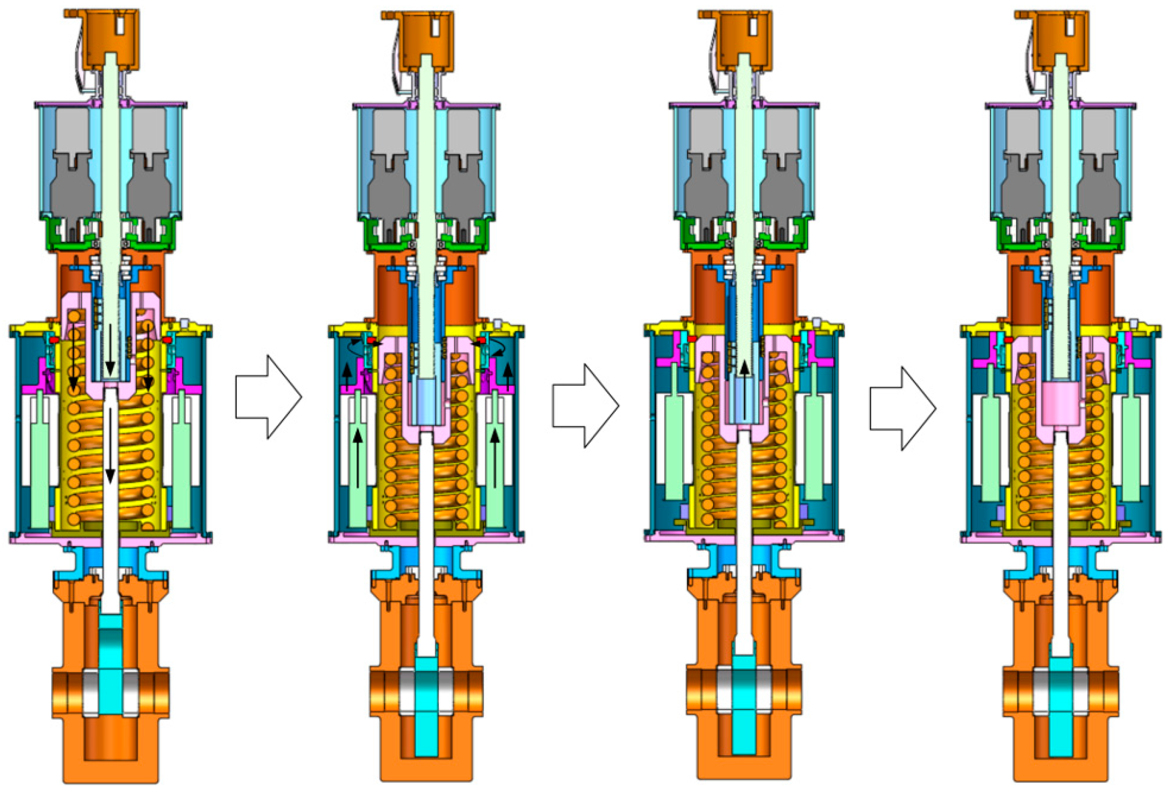
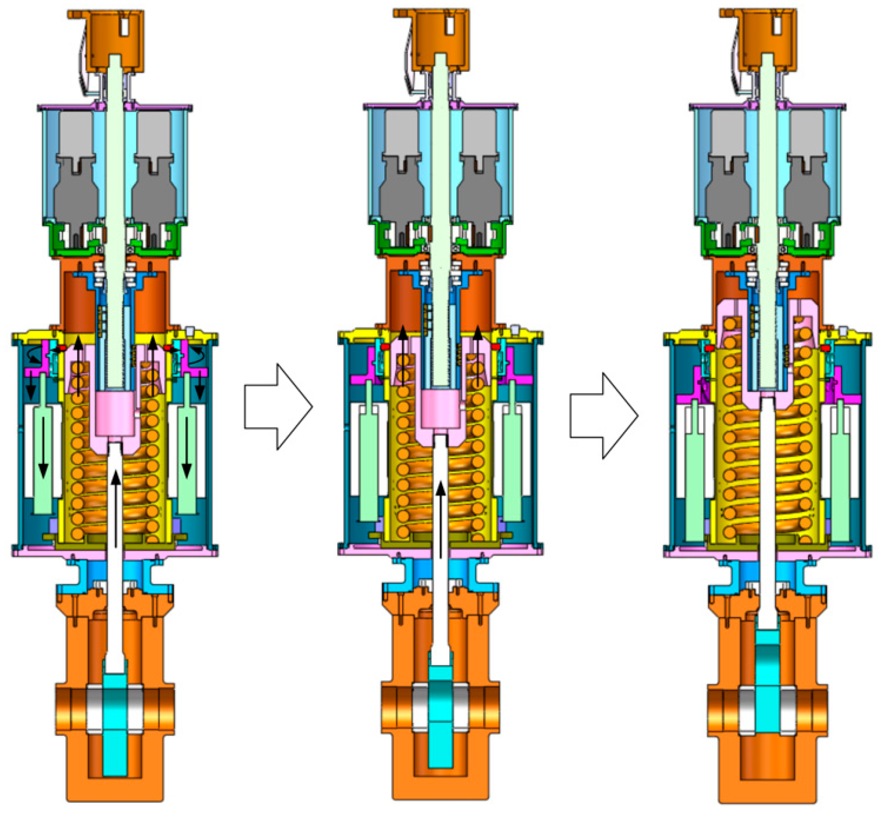
2.4. Working Principle

The working principle of the all-electric subsea gate valve actuator is shown in Figure 10. The master control station (MCS) and electrical power unit (EPU) transmit the communication signals and the power signals to the electrical power and communication distribution unit (EPCDU) through the umbilical. The EPCDU transmits the communication signals to the electric subsea electronic module (ESEM) inside the electric subsea control module (ESCM) through internal routing devices and transforms the transmitted high-voltage electrical signals into the low-voltage electrical signals required by the subsea equipment through internal voltage converters to the ESEM and the drive unit inside the ESCM.
The control unit and drive unit of the actuator need to consider the control mechanism and controller performance to achieve proper operation of the actuator [42,43]. The ESEM is the upper control unit of the actuator, which is usually in a redundant configuration. ESEM not only collects various sensor signals from the Christmas tree pipeline, but also communicates with the driver and data acquisition module in the drive unit to monitor and control the all-electric subsea gate valve actuator. The electrical power for the drive unit is redundantly supplied by the EPCDU. After receiving the control command from the ESEM, the drive unit controls and drives the redundant drive mechanism and low-power holding mechanism in the actuator through the internal driver and control box. After receiving the control signal and power supply from the upper driving unit, the all-electric subsea gate valve actuator opens and closes the subsea gate valve through mechanical transmission and feeds back the status information of the gate valve and drive mechanism.

2.5. Design Process

The design process is shown in Figure 11. The design process of the all-electric subsea gate valve actuator follows the process of design requirement determination, dimensional survey, model development, and mechanical analysis [44,45].
According to ISO 13628 and API 17 standards, the design requirements for the all-electric subsea gate valve actuator were specified. Based on the given opening and closing conditions of the subsea gate valve, the dimensions and materials of the actuator components were selected, and a 3D model was created for multibody system dynamics (MSD) of the moving parts and finite element analysis (FEA) of the structural parts. If the strength, load, and time requirements were not satisfied, the dimensions or materials of the actuator components were changed and MSD and FEA were repeated until the performance satisfied all requirements. After the dimensions and materials of the actuator components were determined, the drive parts, including motors, reducers, and electromagnets, were selected.

3. Prototype

Based on the requirements of functional design, the prototype was developed, as shown in Figure 12. The prototype was a highly integrated piece of electromechanical equipment, consisting of the failsafe closing and low-power holding mechanism, override and position-indicating mechanism, pressure compensator, dual-motor redundant drive mechanism, and subsea gate valve.

3.1. Parameters

The parameters of the all-electric subsea gate valve actuator are listed in Table 5. The actuator operates in water depths up to 500 m, and can control the subsea gate valve with a nominal bore size of 5 1/8 inches and a rated working pressure of 5000 psi.
Compared with similar products, the prototype was equipped with a Class IV ROV operation interface and position-indicating mechanism made for subsea gate valves. The prototype reached the same level in terms of the water depth, controlled gate valve specifications, power supply voltage, and failsafe method. The adopted designs of the redundant drive and low-power holding mechanism have advantages over similar products in driving reliability and energy-efficient operation. However, due to the numerous functional structures of the prototype, there is a slight deficiency in the equipment’s size compared with similar products [12,16,18,25,46].
The proposed concept prototype of the all-electric subsea gate valve actuator has key functions such as a redundant electric drive, condition monitoring, failsafe closing, auxiliary override, position indication, and low-power position holding, and all the main components used to drive and control the movement are integrated inside the actuator in pressure-compensated fluid. The valve’s opening and closing times are less than 3 min, and pressure compensation and corrosion protection are also considered in the design. In addition, according to the standards of ISO 13628-8 and API RP 17H, the CLASS IV rotary docking interface was selected to allow ROVs and divers to override operation. In summary, the prototype achieved Safety Integrity Level 3, satisfying the design standards for subsea production control systems [32].

3.2. Operation Modes

Three operation modes are available for opening and closing the subsea gate valve: normal mode, failsafe closing mode, and emergency mode.

3.2.1. Normal Mode

The opening process of the all-electric subsea gate valve actuator in normal mode is shown in Figure 13. Firstly, the dual-motor redundant drive mechanism outputs power to drive the valve stem downward while continuously compressing the closing spring until the valve is fully opened; then, the low-power holding mechanism is energized and uses the mechanical structure to lock the closing spring to ensure that the valve remains open with the minimum power consumption. Finally, the drive mechanism reverses to the initial position to leave space for the closing spring release.
The closing process of the all-electric subsea gate valve actuator in normal mode is the reversed sequence of the above opening process.

3.2.2. Failsafe Closing Mode

When the subsea gate valve is in the open position, the actuator enters the failsafe closing mode if the AE system breaks down. As shown in Figure 14, in this mode, firstly, the drive mechanism and low-power holding mechanism are power-off simultaneously; then, the low-power holding mechanism is unlocked by the closing spring force; finally, the closing spring drives the valve stem upward until the valve is fully closed.

3.2.3. Emergency Mode

When the drive mechanism of the all-electric subsea gate valve actuator completely fails, the ROV or diver can input additional power to open and close the valve via the override and position-indicating mechanism, which is the emergency mode of the actuator. During the opening or closing operation, the ROV or diver can judge the status of the valve from the motion of the position-indicating rod.

4. Tests

The tests were conducted in the self-developed subsea gate valve actuator test system. The redundant drive function, low-power position holding function, failsafe closing function, and valve position indication function were fully tested.

4.1. Subsea Gate Valve Actuator Test System

Based on the testing requirements, an all-electric subsea gate valve actuator test system was developed, as shown in Figure 15. It was composed of the MCS, EPCDU, signal generator, control device, driving device, and all-electric subsea gate valve actuator to be tested.
A schematic diagram of the test system is shown in Figure 16. The test MCS was used to mimic the real MCS, which is responsible for sending control commands and reading signal data; the EPCDU was used to mimic the power transmission and communication of the AE system; the signal generator was used to mimic the status signal of the pipeline; the control device was used to receive commands from the MCS, control the drive device, and collect sensor data and feedback for the MCS; and the driving device was used to control the drive mechanism and low-power holding mechanism of the actuator.

4.2. Test Results

The functional test results of the all-electric subsea gate valve actuator prototype are summarized below.

4.2.1. Redundant Motor Driving Test

(1)
Dual-motor driving test
The dual-motor driving test was carried out with the test system. Figure 17 shows the monitoring interface during the test; the green light indicated that the valve was in the open position and the red light indicated that the valve was in the closed position. The dual-motor output characteristics and gate valve stem displacement during the testing process are plotted in Figure 18.
As shown in Figure 17 and Figure 18, when the dual-motors worked simultaneously, they were able to complete the opening and closing of the subsea gate valve, and the time spent satisfied the requirements of the subsea production control system. During the test, the synchronization of the dual-motor drive output was good, and only slight fluctuations occurred in the process of increasing or decreasing the output speed. During the opening and closing of the subsea gate valve, the variation of the motor output displacement curve corresponded to the variation of the motor output speed curve very well; the consistency of the valve stem displacement curve and motor output displacement curve was also good, following the same trend.
The dual-motor driving test was repeated 10 times, and every test was successful.
(2)
Single-Motor Driving Test
The power supply of a certain motor was cut off, and the opening and closing of the subsea gate valve solely relied on the other motor. The monitoring interface and test results are shown in Figure 19 and Figure 20, respectively.
As shown in Figure 19 and Figure 20, when the power supply of a certain motor was cut off, the status indicator light of this motor was always off and its displacement and speed signals did not change. The normal motor could still operate normally and was able to open and close the subsea gate valve independently, and its output displacement and speed change still satisfied the driving requirements of the subsea gate valve.
The single-motor driving test was repeated 10 times, and every test was successful.

4.2.2. Low-Power Position Holding Test

The monitoring interface and test results of the low-power position holding test are shown in Figure 21 and Figure 22, respectively.
After the subsea gate valve was fully opened, under the action of the low-power holding mechanism, the displacement signal of the valve stem remained unchanged and the valve was kept in the fully open position as the rotation of the drive mechanism reversed until the motor stopped, showing that the low-power holding mechanism satisfied the functional requirements for the long-term opening of the valve with minimal power consumption.
The low-power position holding test was repeated 10 times, and every test was successful.

4.2.3. Failsafe Closing Test

The monitoring interface and test results of the failsafe closing test are shown in Figure 23 and Figure 24, respectively.
When the subsea gate valve was in the low-power position holding state, the drive mechanism had reversed to the initial position to leave space for the closing spring release. When the power-off occurred in the actuator, the low-power holding mechanism was unlocked smoothly by the closing spring force. The valve stem moved back quickly under the actions of the closing spring and the buffering mechanism until the valve was fully closed and the status indicator light turned red.
The failsafe closing test was repeated 10 times, and every test was successful.

4.2.4. Subsea Gate Valve Position Indication Test

The subsea gate valve position indication test was conducted in the meantime, as shown in Figure 25.
During the opening and closing of the subsea gate valve, the swinging rod and position-indicating rod of the override and position-indicating mechanism moved normally and smoothly in the given direction, and correctly indicated the position of the valve stem.
The subsea gate valve position indication test was repeated 10 times, and every test was successful.

5. Conclusions

To bridge the gap that exists in the key equipment of the new subsea production control system, the all-electric subsea gate valve actuator, and to exploit subsea oil and gas resources with high reliability, energy-efficiency, and safety, this paper proposed a novel concept prototype of an all-electric subsea gate valve actuator. Its key functions included a redundant drive, failsafe closing, auxiliary override, position indication, and low-power position holding, and it satisfied the electrically-driven requirements of subsea gate valves and achieved Safety Integrity Level 3. The prototype was successfully tested in the self-developed subsea gate valve actuator test system and fulfilled the opening and closing control of the subsea gate valve, with a nominal bore size of 5 1/8 inches and a rated working pressure of 5000 psi. The following conclusions can be drawn:
(1)
The proposed redundant drive mechanism with the parallel arrangement of dual motors, combining gear transmission and the nut–screw transmission, was not only able to open and close the subsea gate valve with dual motors, but also independently with a single motor. The output characteristics of both methods satisfy the requirements of the subsea production control system.
(2)
The proposed design of the closing spring and the self-circulating damping mechanism were able to achieve fast and safe closing of the subsea gate valve with minimized impact when the system failed.
(3)
The previously proposed low-power holding mechanism design was applied to the concept prototype. The mechanism was refined to satisfy the requirements of both the holding and unlocking performances. The closing spring could be reliably locked by the mechanism during the long-term opening of the subsea gate valve with minimal power consumption and a cable number for control, and the unlocking process of the mechanism could be automatically completed only by the release of the closing spring, without other auxiliary mechanical structures.
(4)
The proposed override and position-indicating mechanism with the nut–screw transmission and crank slider was found to be suitable for the ROV or diver emergency operation, with a visual indication function of the valve status.
The all-electric subsea gate valve actuator can be used for controlling subsea gate valves of various sizes and rated working pressures, but the dimensions and materials of the actuator components need to be reselected and recalculated, as do the specifications of the drive parts.
The proposed concept prototype is only applicable to the operation of subsea gate valves in the subsea production control system, and cannot satisfy the operational requirements for subsea ball valves or subsea choke valves. This means that full coverage of all valves in the subsea production control system cannot be achieved.
Further work on this all-electric subsea gate valve actuator will include the structural geometry optimization of the actuator components (Part B); an influence analysis of the unsteady flow of the multi-phase production media on the reliability of the actuator operation (Part C); a comprehensive association test and safe reliability analysis with Christmas trees, subsea oil & gas pipelines, and subsea control modules (Part D), etc.

Author Contributions

Conceptualization, H.W., P.J. and L.W.; methodology, H.W. and F.W.; writing—original draft preparation, H.W., P.J. and G.L.; writing—review and editing, F.W., C.L. and F.Y.; visualization, H.W. and Y.W.; supervision, F.W., L.W. and G.L.; funding acquisition, P.J., F.Y. and F.W. All authors have read and agreed to the published version of the manuscript.

Funding

This research was funded by the National Natural Science Foundation of China (52001089); Heilongjiang Provincial Natural Science Foundation of China (LH2021E046); Major Science and Technology Project of China National Offshore Oil Corporation (CCL2022RCPS0707RSN); University Scientific Research Project supported by Guangzhou Municipal Education Bureau (202235301); Science and Technology Project Foundation of Guangzhou Panyu Polytechnic (2023KJ19); Characteristic innovation project of ordinary colleges and universities in Guangdong Province (2022KTSCX293); Tertiary Education Scientific research project of Guangzhou Municipal Education Bureau (202235232).

Institutional Review Board Statement

Not applicable.

Informed Consent Statement

Not applicable.

Data Availability Statement

Not applicable.

Conflicts of Interest

The authors declare no conflict of interest.

References

  1. Zhang, X.; Duan, M.; Mao, D.; Yu, Y. A mathematical model of virtual simulation for deepwater installation of subsea production facilities. Ships Offshore Struct. 2017, 12, 182–195. [Google Scholar] [CrossRef]
  2. Johansen, C.; Rokne, Ø.; Moe, S.; Magnus, H. Real Application of Electric Controls Technology to Subsea System: Success, Learnings and Recommendations. In Proceedings of the Offshore Technology Conference, Houston, TX, USA, 1–4 May 2017. [Google Scholar] [CrossRef]
  3. Bhattacharyya, S.K.; Cheliyan, A.S. Optimization of a subsea production system for cost and reliability using its fault tree model. Reliab. Eng. Syst. Saf. 2019, 185, 213–219. [Google Scholar] [CrossRef]
  4. Shen, W.; Zhang, J.; Sun, Y.; Zhang, D. Effect of cavitation bubble collapse on hydraulic oil temperature. J. Cent. South Univ. 2016, 23, 1657–1668. [Google Scholar] [CrossRef]
  5. Huang, H.; Zhang, S.; Yang, Z.; Tian, Y. Modified Smith fuzzy PID temperature control in an oil-replenishing device for deep-sea hydraulic system. Ocean Eng. 2018, 149, 14–22. [Google Scholar] [CrossRef]
  6. Wilson, A. All-electric subsea well brings benefits vs. traditional hydraulic technology. J. Petrol. Technol. 2018, 70, 65–66. [Google Scholar] [CrossRef]
  7. Monteverde, C.; Novello, M.; Kristiansen, K. A New All Electric Subsea Control System Development. In Proceedings of the Offshore Technology Conference, Houston, TX, USA, 6–9 May 2019. [Google Scholar] [CrossRef]
  8. Orth, A.; Hendrix, G. An Electro-Mechanical Actuator with Hydrostatic Drive for Subsea Trees to Reduce CAPEX and OPEX with Higher Reliability and Safety Levels. In Proceedings of the Offshore Technology Conference, Houston, TX, USA, 30 April–3 May 2018. [Google Scholar] [CrossRef]
  9. Elgsaas, K.M.; Hjertvikrem, T.; Hua, W.; Tryti, S.; Glomsaker, T. All-Electric Subsea Systems—Intelligence on Demand. In Proceedings of the Offshore Technology Conference, Houston, TX, USA, 30 April–3 May 2018. [Google Scholar] [CrossRef]
  10. Li, Z.; Jia, P.; Wang, H.; Zhang, N.; Wang, L. Development trend and active research areas of subsea production system. J. Harbin Eng. Univ. 2019, 40, 944–952. [Google Scholar]
  11. Sotoodeh, K. Actuator selection and sizing for valves. SN Appl. Sci. 2019, 1, 1207. [Google Scholar] [CrossRef]
  12. Abicht, D.; Akker, J.V.D. The 2nd Generation DC All-Electric Subsea Production Control System. In Proceedings of the Offshore Technology Conference, Houston, TX, USA, 2–5 May 2011. [Google Scholar] [CrossRef]
  13. Jia, Y.; Zhao, H. All-electric subsea production control system. Appl. Mech. Mater. 2013, 251, 196–200. [Google Scholar] [CrossRef]
  14. Micali, S. Subsea All-Electric Technology Now Available for the Future Field Developments [EB/OL]. 20 October 2016. Available online: https://www.sut.org/wp-content/uploads/2015/09/Salvatore-Micali-v3-Aker-Solutions-Subsea-All-Electric-Technology-without-notes.pdf (accessed on 17 April 2023).
  15. Oh, J.S.; Kang, S.R. Merits of all-electric subsea production control system. J. Korean Soc. Mar. Eng. 2014, 38, 162–168. [Google Scholar] [CrossRef]
  16. Rokne, Ø. Deepwater developments can benefit from all-electric controls. Offshore 2013, 7, 108–109. [Google Scholar]
  17. Rexroth Bosch Group. SVA R2—The World’s First Subsea Electric Actuator with Safety Spring, as Compact as Hydraulic Cylinders [EB/OL]. 3 May 2021. Available online: https://www.boschrexroth.com/en/xc/sustainable-subsea-operations/ (accessed on 17 April 2023).
  18. Offshore Network. Bosch Rexroth to Present World’s Smallest Electric Subsea Valve Actuator at Hannover Messe [EB/OL]. 16 April 2021. Available online: https://offsnet.com/content/north-sea/bosch-rexroth-to-present-world-s-smallest-electric-subsea-valve-actuator-at-hannover-messe (accessed on 17 April 2023).
  19. OneSubsea. Electric High-Power Rotary Actuator [EB/OL]. 24 June 2018. Available online: https://www.onesubsea.slb.com/-/media/onesubsea/files/product-sheet/oss-high-power-rotary-actuator-ps.ashx (accessed on 17 April 2023).
  20. OneSubsea. Electric Low-Power Rotary Actuator [EB/OL]. 24 June 2018. Available online: https://www.onesubsea.slb.com/-/media/onesubsea/files/product-sheet/oss-low-power-rotary-actuator-ps.ashx (accessed on 17 April 2023).
  21. Winther-Larssen, E. Design of an Electric X-Mas Tree Gate Valve Actuator. Master’s Thesis, Norwegian University of Science and Technology, Trondheim, Norway, 2007. [Google Scholar]
  22. Berven, J. Subsea Production Control Systems for All-Electric Xmas Trees. Master’s Thesis, University of Stavanger, Stavanger, Norway, 2013. [Google Scholar]
  23. Wang, X.; Liu, P.; Jia, P.; Zhang, L.; Wang, H.; Wang, S. Design of an all-electric subsea valve actuator and the strategy for multi-motor synchronous control. China Offshore Oil Gas 2017, 29, 149–156. [Google Scholar]
  24. Xiao, Y.; Wu, D.; Xiang, C.; Li, S. Design of production gate valve and actuator for subsea all-electric Christmas tree. China Petrol. Mach. 2018, 46, 60–64. [Google Scholar] [CrossRef]
  25. Liu, P.; Liu, Y.; Wei, X.; Xin, C.; Sun, Q.; Wu, X. Performance analysis and optimal design based on dynamic characteristics for pressure compensated subsea all-electric valve actuator. Ocean Eng. 2019, 191, 106568. [Google Scholar] [CrossRef]
  26. Liu, P.; Wang, K.; Chen, Q.; Wei, X. Optimization Design and Analysis of Valve Actuator for All-Electric Christmas Tree. In Proceedings of the 20th China Ocean (Offshore) Engineering Symposium, Zhanjiang, China, 15–17 December 2022. [Google Scholar]
  27. Tian, B.; Molinas, M.; Moen, S.; An, Q. High Dynamic Speed Control of the Subsea Smart Electrical Actuator for A Gas Production System. In Proceedings of the 2020 IEEE International Conference on Industrial Technology, Buenos Aires, Argentina, 26–28 February 2020. [Google Scholar] [CrossRef]
  28. Alexandre, O.; Gottfried, H.; Markus, K.; Pedro, J.; Juliano, V. A Novel Subsea Actuator to Electrify Small-Bore Valve. In Proceedings of the Offshore Technology Conference, Virtual and Houston, TX, USA, 16–19 August 2021. [Google Scholar] [CrossRef]
  29. Liu, P.; Shen, D.; Ba, Y.; Cao, J. Development and control strategy of subsea all-electric actuators. J. Ocean Univ. China 2022, 21, 1133–1146. [Google Scholar] [CrossRef]
  30. Glenn-Roar, H.; Henrik, V.; Sigurd, M.; Guttorm, O. Electric Valve Operation Subsea—The 20 First Years. In Proceedings of the Offshore Technology Conference, Houston, TX, USA, 2–5 May 2022. [Google Scholar] [CrossRef]
  31. Carsten, M.; Harald, S.; Birthe, T.; Johannes, R. A Standardized Qualification Approach for Subsea All-Electric Drop-In-Place Actuators. In Proceedings of the Offshore Technology Conference, Houston, TX, USA, 2–5 May 2022. [Google Scholar] [CrossRef]
  32. Alexandre, O.; Amadeu, P.; Gottfried, H. Enabling All-Electric Subsea Control Systems without Compromising Safety—A Case Study Comparing Functional Safety Systems Using Springs or Batteries. In Proceedings of the Offshore Technology Conference, Houston, TX, USA, 2–5 May 2022. [Google Scholar] [CrossRef]
  33. Markus, H.; Sebastian, I.; Markus, G. Sensor design for saltwater ingress detection in high reliable all-electric deep sea actuators. J. Loss Prevent. Proc. 2023, 83, 105033. [Google Scholar] [CrossRef]
  34. Schwerdtfeger, T.; Scott, B.; Akker, J.V.D. World-First All-Electric Subsea Well. In Proceedings of the Offshore Technology Conference, Houston, TX, USA, 1–4 May 2017. [Google Scholar] [CrossRef]
  35. Xiao, X.; Zhao, H.; Wang, Y.; Peng, F.; Duan, M.; Yan, J.; Fan, X. Optimization design of coaxial parallel double spring of subsea valve actuator. Oil Field Equip. 2014, 43, 29–33. [Google Scholar]
  36. Yan, D.; Zhang, J.; Wang, P.; Feng, S. Design for a valve driver of subsea production system. Machinery 2017, 55, 13–15. [Google Scholar]
  37. Akker, J.V.D.; Burdick, J. All-electric actuated subsea system qualified, implemented. Oil Gas J. 2008, 106, 44–50. [Google Scholar]
  38. Stropnik, R.; Sekavčnik, M.; Ferriz, A.M.; Mori, M. Reducing environmental impacts of the ups system based on PEM fuel cell with circular economy. Energy 2018, 165, 824–835. [Google Scholar] [CrossRef]
  39. Dev, B.; Samudrala, O.; Wang, J. Characterization of leak rates in thermoplastic barrier valve seals under high static and cyclic pressure loads. J. Petrol. Sci. Eng. 2016, 145, 279–289. [Google Scholar] [CrossRef]
  40. Wang, H.; Jia, P.; Wang, L.; Yun, F. Design and performance analysis for the low-power holding mechanism of the all-electric subsea gate valve actuator. Appl. Sci. 2020, 10, 6119. [Google Scholar] [CrossRef]
  41. Sotoodeh, K. Conceptual design and selection of a bladder type pressure compensation system for subsea actuators to prevent failure due to seawater head. Int. J. Interact. Des. Manuf. 2021, 15, 673–680. [Google Scholar] [CrossRef]
  42. Paladugu, V.; Bikash, K. Electrohydraulic proportional valve-controlled vane type semi-rotary actuated wind turbine control by feedforward fractional-order feedback controller. Proc. Inst. Mech. Eng. Part I 2022, 236, 318–337. [Google Scholar] [CrossRef]
  43. Qi, M.; Yong, X.; Jie, C.; Tryphon, T. Implementation-oriented filtered PID control: Optimization of robustness margins. Automatica 2023, 152, 110974. [Google Scholar] [CrossRef]
  44. Francis, K.; Shemphang, M.; Teiborlin, M.; Bikash, K. Design and development of the pineapple harvesting robotic gripper. Commun. Control Robot. Syst. 2022, 229, 437–454. [Google Scholar] [CrossRef]
  45. Muhammad, N.; Usman, T.; Waseem, S. Fracture mechanics analysis of a closure head of a PWR reactor pressure vessel the effect of bolt pre-load and thermal stresses. Ann. Nucl. Energy. 2023, 189, 109843. [Google Scholar] [CrossRef]
  46. Cai, B.; Zhao, Y.; Liu, H.; Min, X. A data-driven fault diagnosis methodology in three-phase inverters for PMSM drive systems. IEEE Trans. Power Electr. 2017, 32, 5590–5600. [Google Scholar] [CrossRef]
Figure 1. All-electric subsea gate valve actuator.
Jmse 11 01043 g001
Figure 2. The closing spring in the state of (a) compression and (b) release.
Jmse 11 01043 g002
Figure 3. Buffering mechanism of the actuator. (a) Configuration and (b) principle.
Jmse 11 01043 g003
Figure 4. Dual-motor redundant drive mechanism.
Jmse 11 01043 g004
Figure 5. Low-power holding mechanism.
Jmse 11 01043 g005
Figure 6. Locking and holding process of the low-power holding mechanism.
Jmse 11 01043 g006
Figure 7. Bladder pressure compensator.
Jmse 11 01043 g007
Figure 8. Override and position-indicating mechanism.
Jmse 11 01043 g008
Figure 9. Indicated position of the position indicating mechanism: (a) open, (b) closed.
Jmse 11 01043 g009
Figure 10. Working principle diagram of the all-electric subsea gate valve actuator.
Jmse 11 01043 g010
Figure 11. Design flowchart of the all-electric subsea gate valve actuator.
Jmse 11 01043 g011
Figure 12. All-electric subsea gate valve actuator prototype.
Jmse 11 01043 g012
Figure 13. The opening process of the all-electric subsea gate valve actuator in normal mode.
Jmse 11 01043 g013
Figure 14. The failsafe closing mode of the all-electric subsea gate valve actuator.
Jmse 11 01043 g014
Figure 15. Subsea gate valve actuator test system.
Jmse 11 01043 g015
Figure 16. The schematic diagram of the subsea gate valve actuator test system.
Jmse 11 01043 g016
Figure 17. The monitoring interface of the dual-motor driving test: (a) the valve is closed, (b) the valve is opening, (c) the valve is open.
Jmse 11 01043 g017
Figure 18. Dual-motor driving test results: (a) the motor output curve; (b) the displacement curve of the valve stem.
Jmse 11 01043 g018
Figure 19. The monitoring interface of the single-motor driving test: (a) the valve is closed, (b) the valve is opening, (c) the valve is open.
Jmse 11 01043 g019
Figure 20. Single-motor driving test results: (a) the motor output curve; (b) the displacement curve of the valve stem.
Jmse 11 01043 g020
Figure 21. The monitoring interface of the low-power position holding test: (a) the valve is open, (b) the valve remains open.
Jmse 11 01043 g021
Figure 22. Low-power position holding test results: (a) the motor output curve; (b) the displacement curve of the valve stem.
Jmse 11 01043 g022
Figure 23. The monitoring interface of the failsafe closing valve test: (a) the valve is open, (b) the failsafe closing process, (c) the valve is closed.
Jmse 11 01043 g023
Figure 24. Failsafe closing valve test results: (a) the motor output curve; (b) the displacement curve of the valve stem.
Jmse 11 01043 g024
Figure 25. Subsea gate valve position indication test results: (a) the valve is closed, (b) the valve is opening, (c) the valve is open.
Jmse 11 01043 g025
Table 1. Parameters of the closing spring.
ParametersUnitValue
Line diametermm40
Mean diametermm240
Spring rateN/mm150.5
Number of active coilscoil12
Preload (closed valve)N40,033
Ultimate loadN61,840
Table 2. Parameters of the buffering mechanism.
ParametersUnitValue
Thickness of the spring support cylindermm53
Internal diameter of the cavitymm325
Number of damping holes/2
Diameter of damping holesmm2.4
Kinematic viscosity of the insulating oilmm2/s9.252
Density of the insulating oilg/mm38.95 × 10−4
Table 3. Dual-motor redundant drive mechanism specification.
MotorsReducers
ParametersValue/DescriptionParametersValue/Description
TypeBrushless DC motorTypePlanetary reducer
Input voltage340 V DCReduction ratio50
Rated torque34 NmEfficiency94%
Rated speed1000 rpmOutput speed20 rpm
Rated power3.68 kWOutput torque1598 Nm
Table 4. Low-power holding mechanism parameters.
ParametersUnitValue
Number of electromagnets/6
Holding forceN2700
Holding powerW180
Lockable maximum loadkN70.48
Unlocking torqueNm468.53
Table 5. All-electric subsea gate valve actuator parameters.
ParametersUnitValue
Working depthm500
Output opening forcekN240
Output closing forcekN40
Working strokemm144
Power supply voltageV DC340
Opening powerkW3.68
Holding powerW180
Opening and closing valve times53
Failsafe closing times6
ROV interfacelevelCLASS IV
Disclaimer/Publisher’s Note: The statements, opinions and data contained in all publications are solely those of the individual author(s) and contributor(s) and not of MDPI and/or the editor(s). MDPI and/or the editor(s) disclaim responsibility for any injury to people or property resulting from any ideas, methods, instructions or products referred to in the content.

