Article

Ship Intrusion Collision Risk Model Based on a Dynamic Elliptical Domain

1
Navigation College, Dalian Maritime University, Dalian 116026, China
2
Key Laboratory of Navigation Safety Guarantee of Liaoning Province, Dalian Maritime University, Dalian 116026, China
*
Author to whom correspondence should be addressed.
J. Mar. Sci. Eng. 2023, 11(6), 1122; https://doi.org/10.3390/jmse11061122
Submission received: 20 April 2023 / Revised: 21 May 2023 / Accepted: 23 May 2023 / Published: 26 May 2023
(This article belongs to the Special Issue Application of Advanced Technologies in Maritime Safety)

Abstract

:
To improve navigation safety in maritime environments, a key step is to reduce the influence of human factors on the risk assessment of ship collisions by automating the decision-making process as much as possible. This paper optimizes a dynamic elliptical ship domain based on Automatic Identification System (AIS) data, combines the relative motion between ships in different encounter situations and the level of ship intrusion in the domain, and proposes a ship intrusion collision risk (SICR) model. The simulation results show that the optimized ship domain meets the visualization requirements, and the intrusion model has good collision risk perception ability, which can be used as the evaluation standard of ship collision risk: when the SICR is 0.5–0.6, the ship can establish a collaborative collision avoidance decision-making relationship with other ships, and the action ship can take effective collision avoidance action at the best time when the SICR is between 0.3 and 0.5. The SICR model can give navigators a more accurate and rapid perception of navigation risks, enabling timely maneuvering decisions, and improving navigation safety.

1. Introduction

The International Maritime Organization (IMO) estimates that the international shipping industry is responsible for >80% of global trade and >70% of its value [1]. Continuous progress in science and technology has further promoted ship development in the direction of large scales, specialized functions, high speeds, and unmanned driving. However, despite advances in navigation technology, ship collisions, stranding, and reef accidents still occur. The European Maritime Safety Agency [2] reported that an average of 3200 maritime accidents occurred each year from 2016 to 2020 and mainly comprised instances of equipment failure, capsizing, collision, reefing, fire, and stranding. Ship collisions are of particular concern, and the development of intelligent navigation systems that reduce or avoid their occurrence has become a focus of research on maritime autonomous surface ships. The European Maritime Safety Agency has reported that more than 50% of maritime accidents are related to human error, which implies that navigation safety can be improved by increasing automation and reducing the participation of humans in the decision-making and operation processes of ship collision avoidance systems. The maritime environment is complex and changeable with not only static obstacles such as coastlines, islands, reefs, and wrecks but also dynamic unknown obstacles and other ships [3]. Thus, ship collision avoidance is very important for safe navigation.
Ship collision avoidance involves analyzing the movement patterns of ships, evaluating whether relevant parameters satisfy the safety threshold, and consulting the International Regulations for Preventing Collisions at Sea (COLREGs) in different situations. Automating the decision-making process for collision avoidance and path planning involves considering the responsibilities of ships, action modes, and shipbuilding technology. Measuring the collision risk has long been a key research direction in the field of maritime traffic engineering. The concepts of the ship domain and degree of collision risk provide a theoretical basis for ship collision avoidance.
Various studies have developed different approaches to assess the margin of safety between ships. Liu et al. [4] used the distance at the closest point of approach (DCPA), time to the closest point of approach (TCPA), and distance between two ships as variables and proposed a collision risk function based on fuzzy theory. Shu and Yu [5] used the same approach to establish a fuzzy function model. However, their model inevitably incorporates errors because some of the parameters are determined by the navigator’s experience, which introduces a human factor. Zhen et al. [6] proposed a real-time multiship collision risk assessment framework for maritime traffic, where a DBSCAN clustering algorithm is used to process Automatic Identification System (AIS) data to obtain clusters of ship encounters and establish a negative exponential function that characterizes the collision risk. However, their framework only considers a few influencing factors. Chen et al. [7] used a ship collision risk assessment method based on speed obstacles to evaluate the ship collision risk from the perspective of speed. Huang and van Gelder [8] proposed an improved time-varying collision risk measurement method based on the ratio between a ship’s dangerous maneuvers and achievable maneuvers. Liu et al. [9] used field theory and an asymmetric Gaussian function to construct a ship collision risk field in which they used the field potential as an index of the navigation risk. However, they did not consider the time domain.
Some scholars have used the ship domain to evaluate the collision risk. The ship domain is a concept first proposed by Fuji [10], which is defined as “a two-dimensional area surrounding a ship which other ships must avoid; it may be considered as the area of evasion”. Ship domains can be roughly divided into those determined empirically, those based on experts’ knowledge, and those developed by theoretical analyses [11].
The method based on empirical data is to model the ship domain based on navigation data using specific waters. The earliest ship domain used statistical methods to process radar data [10,12,13]. With the development of navigation technology and equipment, AIS data has gradually replaced radar data, and more advanced statistical methods are applied to data processing to establish its ship domain [14,15]. Sun et al. [16,17] studied collision avoidance decisions through questionnaires and inquiries by investigating a ship officer’s efforts to avoid collision with other ships. Simultaneously, the ship avoidance situation under various encounter situations was distinguished, and the ship domain under different navigation settings was established. These ship domain models had additional environmental impact factors compared with traditional ship domain models. Pietrzykowski et al. [18,19] discretized a ship based on the different headings and orientations of the target ship in a multiship encounter situation. Through statistical analysis of the collected data combined with the theory of the Collision Risk Index (CRI), a ship domain model surrounded by regular polygons was established. This ship domain model was affected by the ship officer’s knowledge and the proper orientation of the target ship. Hansen [14] used a large amount of AIS data to study the ship domain from four years of observation and data statistics in the southern waters of Denmark and established a ship domain model for open waters. The knowledge framework-based approach is to utilize appropriate tools to acquire and apply expert navigation knowledge and experience and to determine the ship domain based on this descriptive knowledge [19]. Zhu et al. [20] established a ship domain model based on a neural network to evaluate the risk of ship collision, which considers the influence of visibility and maneuverability. Pietrzykowski et al. [18] proposes the crisp and fuzzy domains of irregular polygons by studying the influence of the length of the ship and the target ship on the ship domain. The ship domain based on analytical expression determines the ship domain according to the ship boundary expression, which is largely parameterized to include more factors related to collision risk. The main idea of the ship domain model based on the analysis representation is to add factors such as ship position, speed, and heading to the ship domain model construction so that the size of the ship domain is affected by these factors. The mathematical function model is used to construct the state equation of ship motion, and then the minimum safety distance between ships is obtained to determine the size of different parts of the ship domain model. Based on analytical expression, the ship domain can quantify the domain boundary through the function equation, which is convenient for practical application and simulation. Compared with determining the ship domain based on experience and knowledge, due to the addition of ship behavior parameters, the actual maneuverability of the ship is dominant in ship domain modeling, which weakens the influence of expert knowledge and statistical results. However, due to the emphasis on ship maneuvering performance and the weakening of the influence of relevant environmental factors, it is difficult for such ship domain models to meet the needs of inter-ship action in specific environments. Nevertheless, this method still satisfies the space collision risk assessment of ships in open waters. Wang [21,22] used a neural network and fuzzy theory to construct a space collision risk model based on the ship domain. Wang et al. [23] proposed a model for the real-time perception of the ship collision risk that incorporates two domain-based approach parameters: the degree of domain violation and the time to domain violation. Their model uses the static elliptical domain proposed by Szlapczynski and Szlapczynska [24]. Liu et al. [25] proposed the concepts of a maximum interval between two ship domains and the degree of violation of two ship domains. They then constructed a risk assessment model for ship collisions that uses the intersection degree between two ship domains and the conservation of momentum. Their model improves upon traditional methods based on the closest point of approach and the spatial domain by providing a continuous and intuitive degree of collision risk.
In summary, existing research has mainly quantified the collision risk between ships according to relative motion parameters, such as changes in the DCPA and TCPA. Although this approach is simple to calculate, it does not consider the influence of a ship’s scale and maneuverability. Incorporating more influencing factors can improve the accuracy of collision risk assessments. Meanwhile, risk assessment methods based on the ship domain mainly use the position and distance of a target ship entering the ship domain. In other words, they only consider the spatial factors of ship collisions [26] and ignore temporal factors. Li et al. [27] addressed the above shortcomings by proposing a dynamic elliptical ship domain that varies with a ship’s speed and maneuverability parameters as well as the encounter situation. The size of the model changes dynamically with the speed of the ship in different encounter situations, which is in line with actual sailing situations at sea. However, one of the problems with this method is its lack of specificity, which may make it difficult for navigators to evaluate the risk of collision and hinders the practical usefulness of the model. In this study, our objective was to verify and improve upon Li et al.’s dynamic elliptical ship domain by using AIS data and incorporating the orientation and distance between ships. We developed the ship intrusion collision risk (SICR) model to quantify the collision risk and to aid in the decision-making process for collision avoidance. We applied the proposed model to different examples of encounter situations to demonstrate its usefulness for guiding autonomous collision avoidance.
The rest of the paper is organized as follows: Section 2 describes the concept of the dynamic elliptical ship domain and the incorporation of AIS data. Section 3 presents the proposed SICR model. Section 4 presents the application of the proposed SICR model to different encounter situations. Section 5 presents the conclusions and future work.

2. AIS Data-Driven Dynamic Elliptical Ship Domain

The concept of a ship domain is reflected in COLREGs, where ships are required to pass each other and obstacles at a safe distance. This safe distance represents the ship domain. Many types of ship domain models are available, which can be roughly grouped into static, dynamic, and fuzzy boundary domain models. Table 1 summarizes some representative models, where the abbreviations OS and TS represent “own ship” and “target ship”, respectively. Static ship domain models apply a fixed safe distance to ships of different sizes and motion states, which is not in line with actual needs. The ship domain can be regarded as an area with the ship at the center, where the size of the area is determined by the length, width, and speed of the ship. The ship domain can be used to ensure navigation safety and avoid collisions. Thus, we selected the dynamic elliptical ship domain [27] that facilitates modeling as the basis for quantifying the collision risk. The dynamic elliptical ship domain fully considers COLREGs, the ship handling experience of the navigator, the ship speed and maneuverability, and other factors, which makes it more suitable for collision avoidance than the other ship domain models.

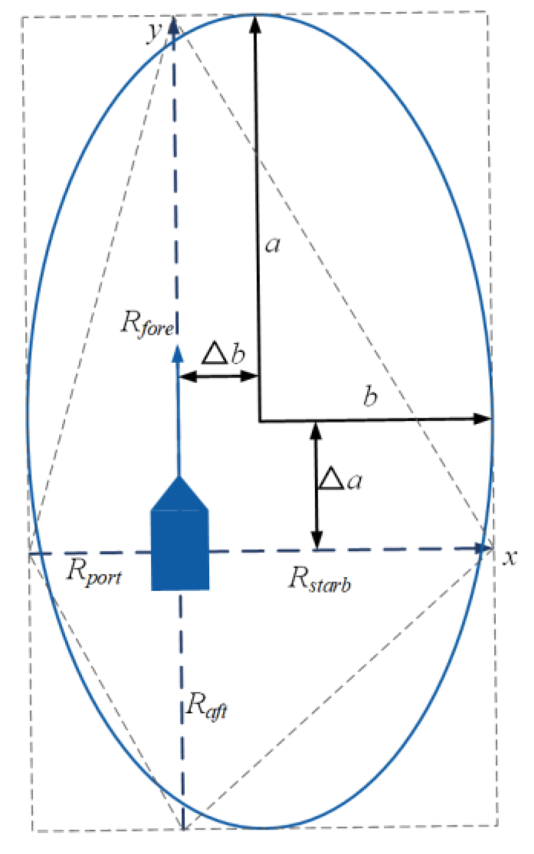
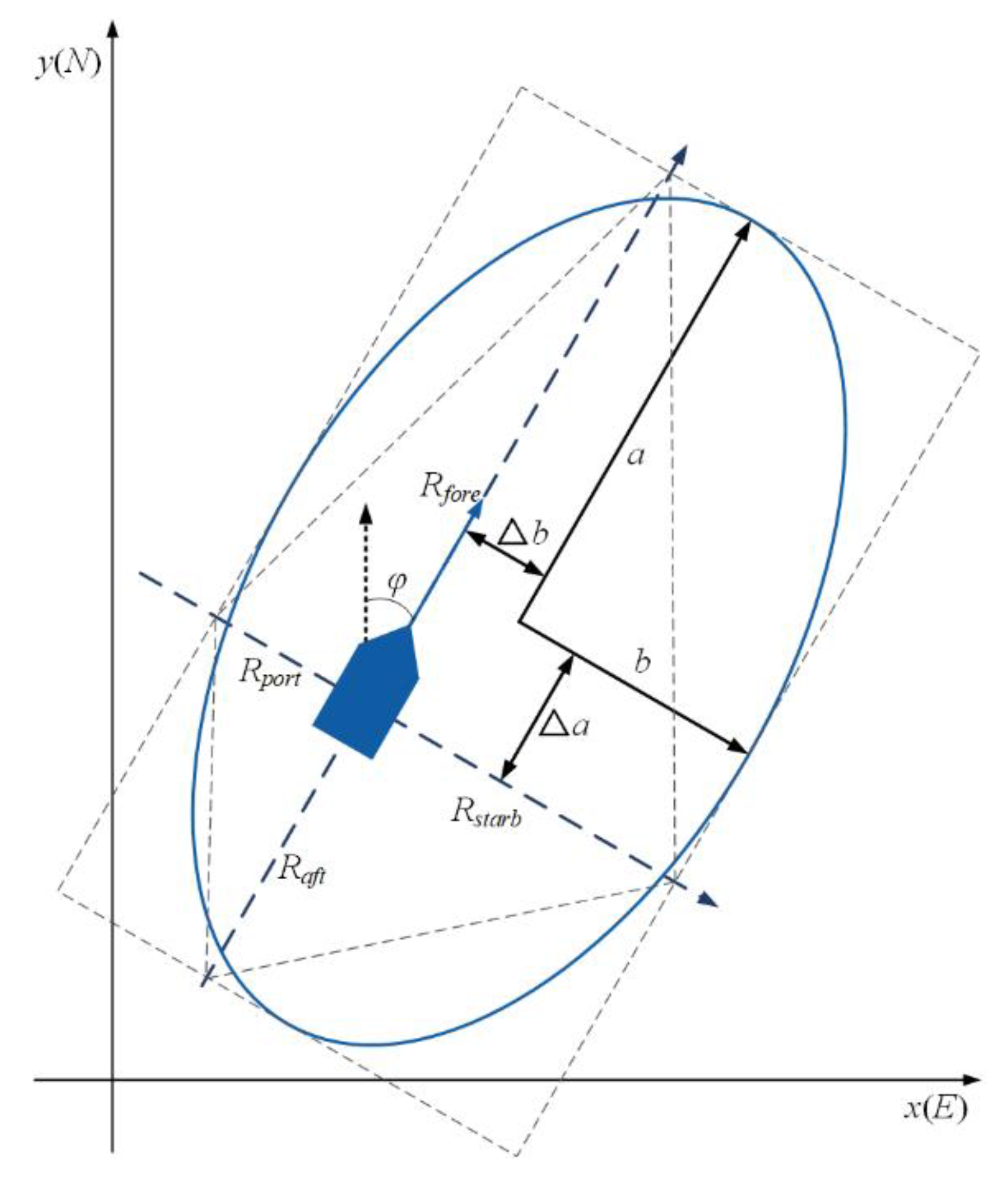
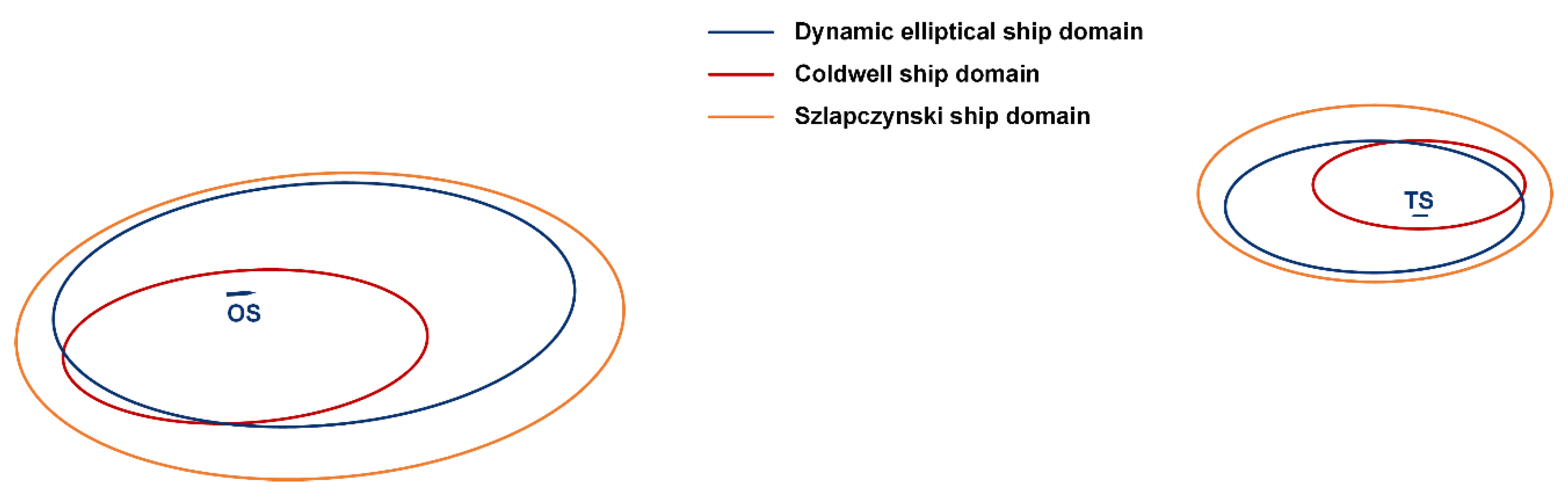
2.1. Dynamic Elliptical Ship Domain

As shown in Figure 1, the center of a ship can be taken as the origin of the Cartesian coordinate system. Then, the positive direction of the x-axis is toward starboard, and the positive direction of the y-axis is toward the bow. The boundary of the dynamic elliptical ship domain is given as follows:
( x Δ a ) 2 a 2 + ( y Δ b ) 2 b 2 = 1 ,
where a and b are the long and short axes, respectively; Δ a is the offset of the ship from the center of the ellipse to the stern along the long axis; and Δ b is the offset of the ship along the short axis. These parameters can be calculated from the four radii of the quaternion ship domain [21]:
a = R f o r e + R a f t 2 , b = R s t a r b + R p o r t 2
Δ a = R f o r e a , Δ b = R s t a r b b ,
where ( R f o r e , R a f t , R p o r t , R s t a r b ) represent the radii in the fore, after, portside, and starboard directions around the ship and can be optimally calculated according to the blocking area estimation method [33]:
R f o r e = ( 1.67 0.67 + s ) T 90 v R a f t = 1.67 0.67 T 90 v R s t a r b = 0.2 L + D T R p o r t = 0.2 L + 0.75 D T ,
where L and v are the ship length and speed, respectively; s is the coefficient used to consider the influence of different encounter situations, T 90 is the time required for the OS to rotate 90°, and D T is the tactical diameter.
s can be calculated as follows:
s = 2 ( v v t ) v ,   head   on s = 2 α π ,         crossing s = 1 ,        overtaking ,
where v t is the speed of the TS and α is the heading angle between the OS and TS, as shown in Figure 2. Although T 90 and D T are easy to obtain for the OS, they are usually difficult to obtain for the TS. They can be obtained from ship motion parameters. In this study, we used the following empirical formula to calculate T 90 :
T 90 = 0.67 v ( A D 2 + ( D T 2 ) 2 ) ,
where A D is the advance from the centroid of a ship at the beginning of the rudder to the distance of the ship’s longitudinal cutting surface when the bow turns 90°. In general, a larger advance indicates a slower steering response. A D and D T can be estimated by the following empirical formulas:
log ( A D L ) = 0.3591 log v + 0.0952
log ( D T L ) = 0.5441 log v 0.0795 ,
where v is the ship speed in knots.

2.2. Incorporation of AIS Data

AIS data contain a wealth of information on ship traffic, including static information such as the ship MMSI number, type, navigation, and size as well as dynamic information such as the ship speed, course, and position (longitude and latitude) [34]. AIS data can be used to understand the navigation intentions of the OS and surrounding TSs in real time. The transmission rate of AIS data varies from 2 s to 3 min depending on the ship speed and turning rate [35]. In this study, we incorporated AIS data to develop the dynamic elliptical ship domain for collision risk assessment. The coordinate system with the ship fixed at the origin can be converted to the ground coordinate system used for the AIS data, as shown in Figure 3.
For the OS, φ O S is the course, v O S is the speed, and ( x O S , y O S ) are the coordinates. In the ground coordinate system, the positive direction of the y-axis is to the north. The ground coordinate system can be used to incorporate the ship length, speed, and heading from the AIS data in the dynamic elliptical ship domain, which changes in size depending on the speed and maneuverability parameters.
In the dynamic elliptical ship domain, the offset parameters are presented in meters. Therefore, these parameters needed to be converted to ensure unit consistency in the subsequent algorithm calculations and visual display. The general conversion formula for navigation is as follows:
1 n   mile = 1852.25 9.31 cos ( 2 φ )   m .
The length of 1 nautical mile is usually fixed at 1852 m; the error caused by this process is not large and can be ignored. To simplify the calculation, we similarly defined 1 nautical mile as equal to 1852 m. Therefore, the offset parameters can then be calculated as follows:
a = k ( R f o r e + R a f t ) , b = k ( R s t a r b + R p o r t )
Δ a = k R f o r e a , Δ b = k R s t a r b b ,
where a , b , Δ a , and Δ b are the latitude of a ship and k is the conversion factor with a numerical value of 1/222240. Then, ( x O C , y O C ) are the new coordinates for the center of the dynamic elliptical ship domain, which can be calculated as follows:
x O C = Δ b cos φ O S Δ a sin φ O S + x O S y O C = Δ b sin φ O S + Δ a cos φ O S + y O S .
The boundary equation of the domain is given by
( x x O C ) sin φ O S + ( y y O C ) cos φ O S 2 a 2 + ( x x O C ) cos φ O S ( y y O C ) sin φ O S 2 b 2 = 1 .

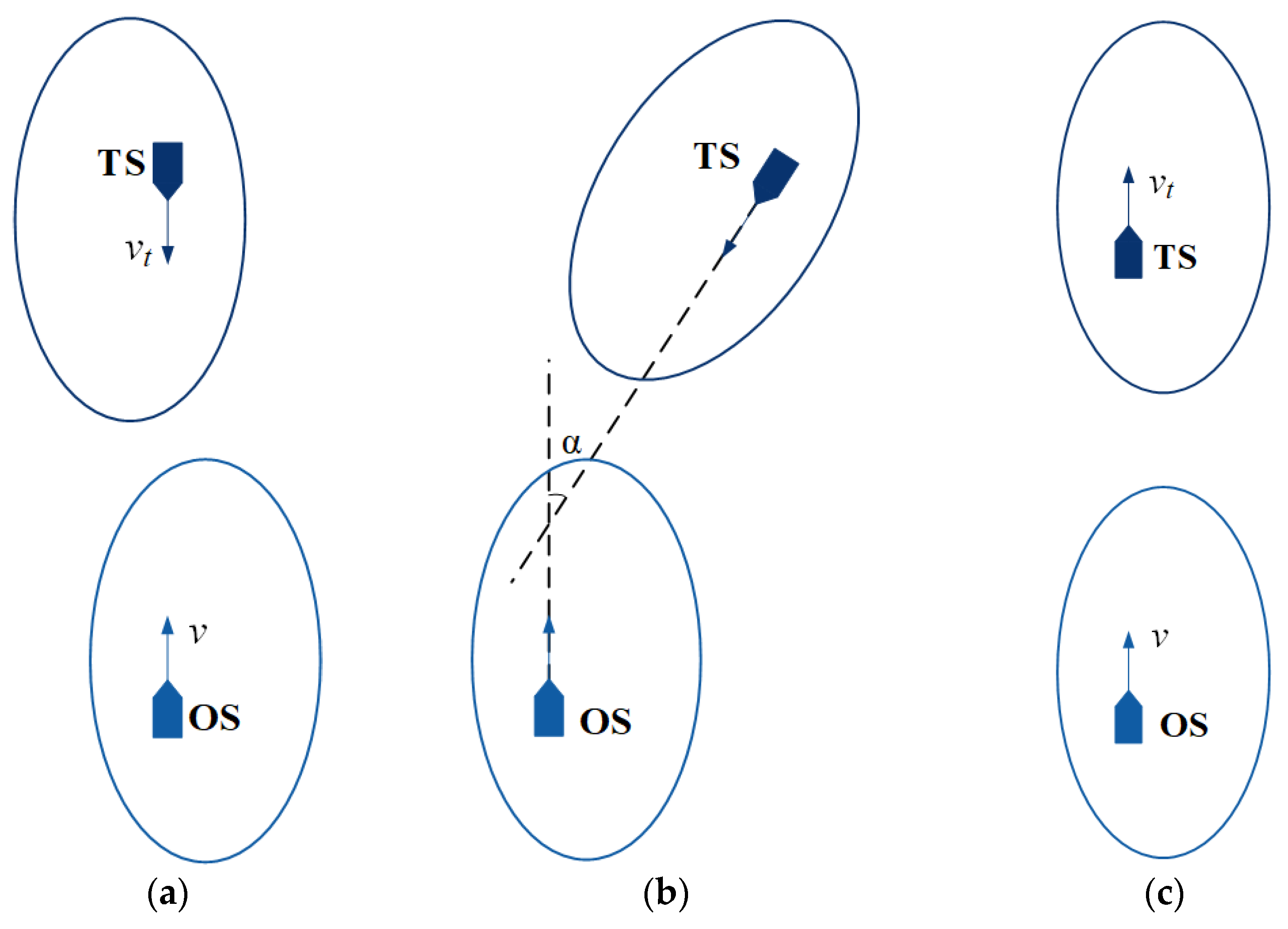
2.3. Domain-Based Safety Criteria

Ship domains can be static, dynamic, or fuzzy boundary models. Depending on the definition of the ship domain and safety criteria, such models may obtain different values for the spacing between ships. Figure 4 shows four safety criteria that are applicable to all ship domain models [11]:
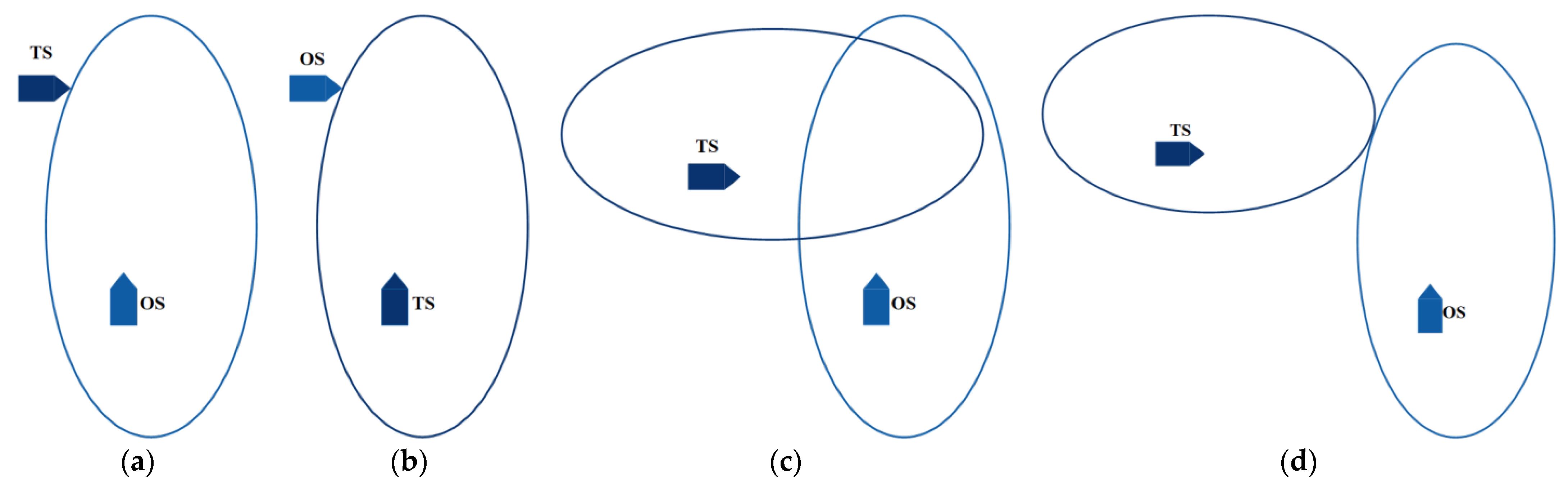
  • The OS domain should not be invaded by the TS;
  • The TS domain should not be invaded by the OS;
  • Neither the OS nor TS should invade each other’s domain;
  • The OS and TS domains should not overlap.
These four criteria were proposed to accommodate the different types of ship domains, which can have large differences. The size and shape of the ship domain greatly affect the effective safe distance between ships. Criteria 1 and 2 may be considered asymmetric: even if the same type of ship domain is used, they may lead to different safety assessments depending on which ship (i.e., OS or TS) is considered. Criteria 3 and 4 may be considered symmetric: as long as the same type of ship domain is applied, the safety assessment of the encounter will be the same, regardless of which ship is considered. In open waters, the collision between two ships will result in greater loss for smaller ships. Thus, we adopted criteria 1 and 2 for the dynamic elliptical ship domain with a center offset to fully consider the responsibilities of the two ships for collision avoidance. We decided against adopting criteria 3 and 4 to avoid the excessive pursuit of nonoverlapping ship domains, which would lead to early decision-making and excessive collision avoidance actions.

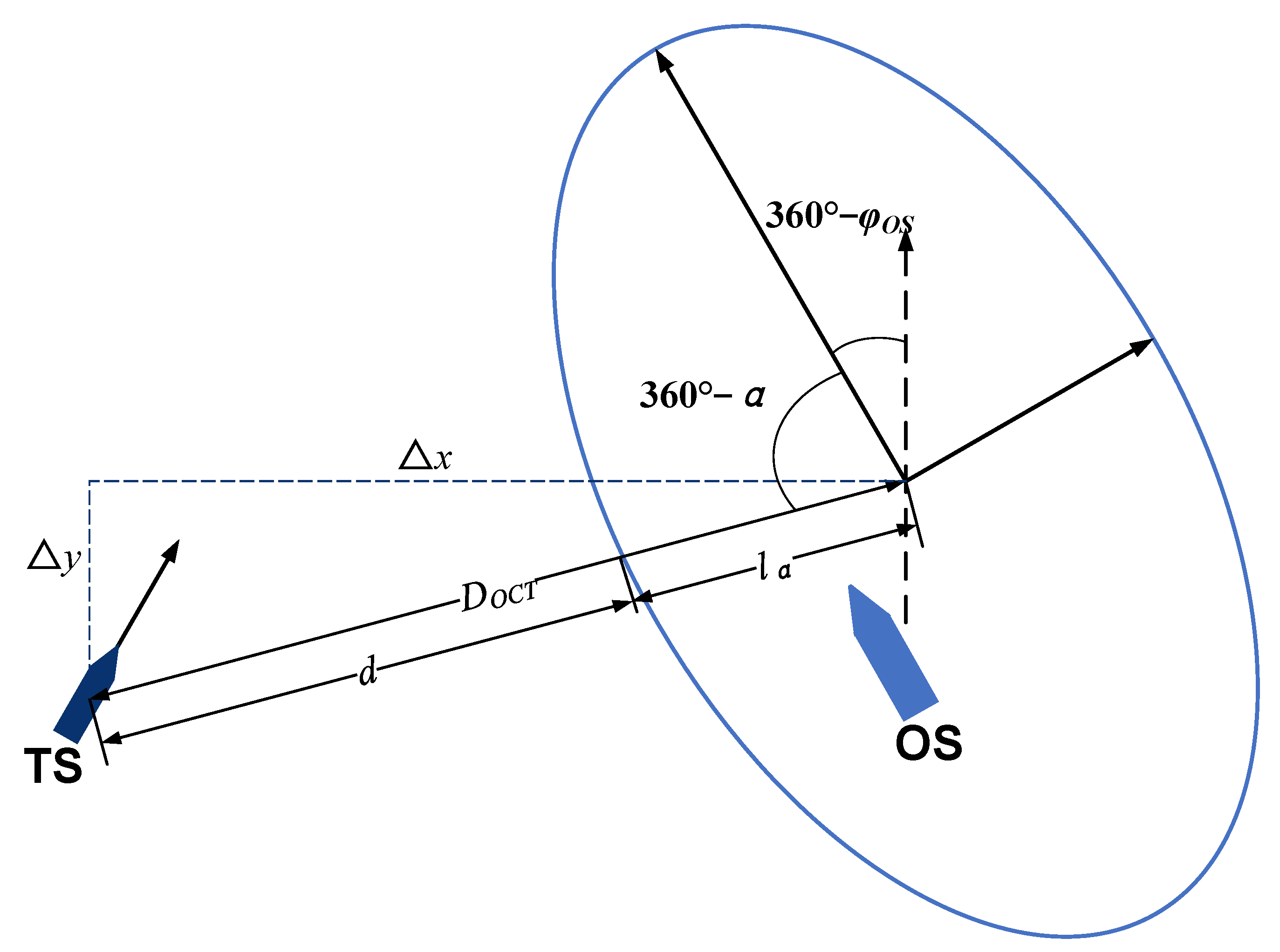
2.4. Calculation of Domain Parameters

To verify the superiority of the AIS data-driven dynamic elliptical ship domain, we compared it against the off-center ship domains of Coldwell [13] and Szlapczynski [24]. Figure 5 plots the sizes of the three domains for the two ships in the head-on encounter situation. Table 2 presents the basic parameters for the two ships, and Table 3 presents the initial information of the simulation experiment.
The ship YUKUN had a smaller domain than the ship YUPENG. Both domains had a large area in the fore direction, small area to the aft, large area to starboard, and small area to port. In actual navigation situations, the required safe distance increases with the ship size and speed. The ship domains of Coldwell and Szlapczynski are only determined by the ship length and do not consider the ship maneuverability. If the ship domain is too small, when a TS invades the OS domain, this will lead to a small safe distance and an inability to detect the collision risk. However, if the ship domain is too large, this can result in frequent early warnings, which are not conducive to collision avoidance actions. The dynamic elliptical ship domain is of appropriate size and meets the needs of actual navigation. Therefore, we adopted the dynamic elliptical ship domain for our proposed SICR model.

3. Ship Intrusion Collision Risk Model

The CRI is a coefficient that is used to measure the degree of risk of collision between ships. It can be used for collisions not only between ships but also between ships and static obstacles. The DCPA and TCPA are widely used parameters to judge the risk of ship collision and to determine whether to adopt collision avoidance behavior and which behavior to adopt. Because the CRI is independent of the research object, it is a subjective measure of the collision risk, which can introduce a human factor to the decision-making process and lead to serious consequences. Therefore, an objective approach is needed to quantify the degree of collision risk from encounters with TSs. Meanwhile, the COLREGs specify that collision avoidance actions should be performed “early.” However, they do not quantify the term “early” and only use it qualitatively. Navigation experts have different views on “early” and may define it according to time, distance, or both. We introduce the SICR to quantify the collision risk between ships from the perspectives of both distance and time. The timing of collision avoidance is calculated according to the concepts of the ship domain and moving boundary.

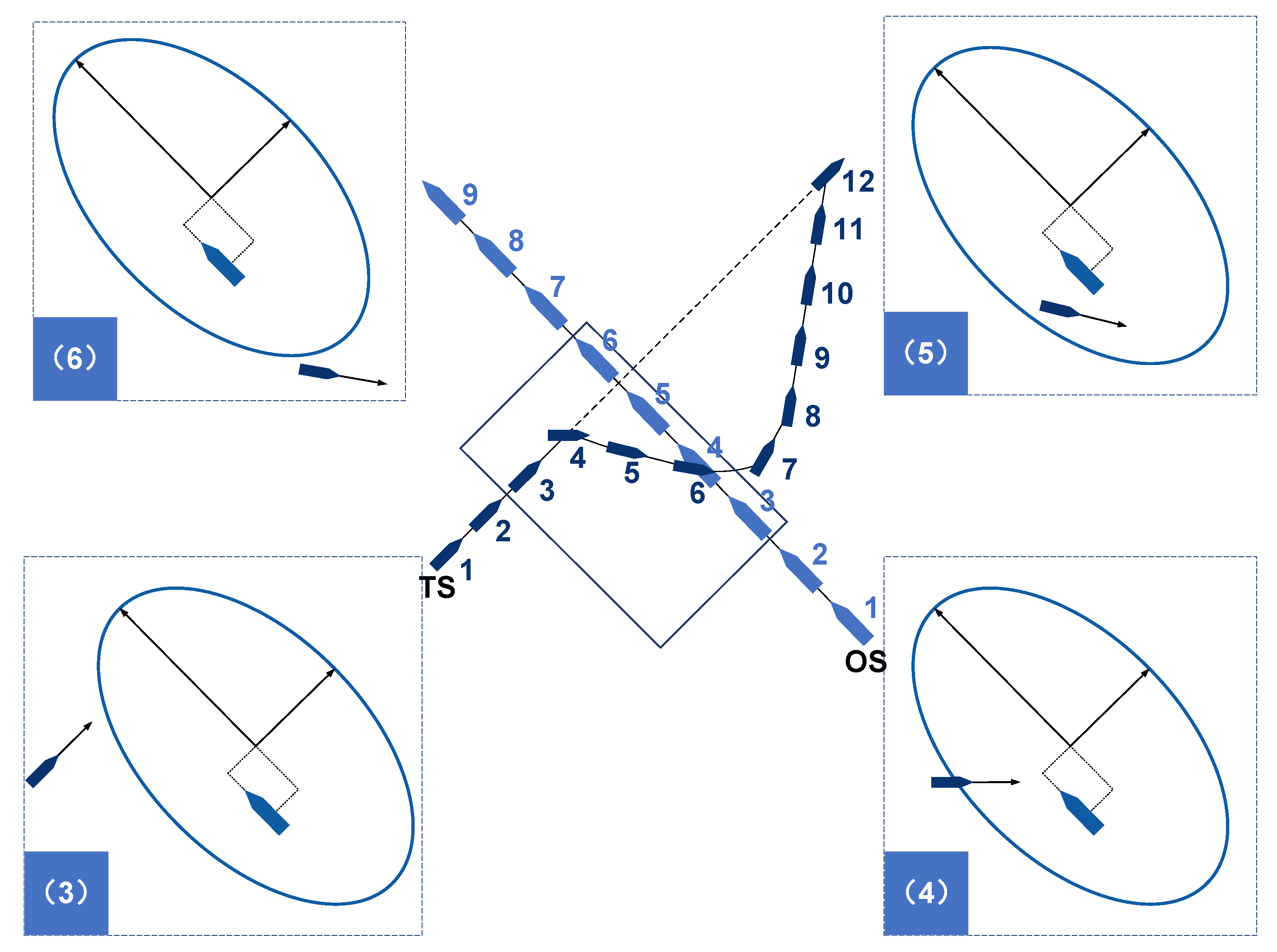
3.1. Ship Intrusion Collision Risk

Consider a TS sailing in open waters that encounters an OS in a crossing situation, as shown in Figure 6. The TS adheres to the collision avoidance principle of early action and large-scale steering. The TS sails from the initial position (marked as 1) to the point where it initiates the avoidance action (4). It then turns right and sails to the point of re-navigation (6). After the OS passes by completely, the TS turns back toward the preplanned route (7) and then resumes its original trajectory (12).
Because the distance between the ships cannot describe the complexity of the encounter, other parameters must be used. However, the severity of the collision risk decreases as the distance between the two ships increases [36]. In addition, the distance is not simply between the centers of the two ships but the distance from the TS to the boundary of the OS domain. This is because the navigator should keep a large distance between ships of different sizes, as shown in Figure 7. In a mathematical model, this relationship can be explained by the fact that the distance from the TS to the boundary of the OS domain is inversely proportional to the distance from the TS to the center of the OS domain. We define this relationship as the SICR, where the distance from the TS to the boundary of the OS domain is expressed by d . To quantify the risk and identify the difference between TSs approaching and leaving the OS domain, the SICR is divided into three stages.
  • The TS is outside the OS domain: the TS is sailing toward the OS domain (Figure 6(3)), so d > 0 .
  • The TS is within the OS domain: the TS enters the OS domain, reaches the maximum degree of intrusion, and sails out of the domain (Figure 6(4,5)), so d < 0 .
  • The TS is outside the ship domain: the TS is leaving the OS domain (Figure 6(6)), so d > 0 .
    S I C R 1 d , T S d o m a i n O S   and   d > 0 T S d o m a i n O S   and   d < 0 T S d o m a i n O S   and   d > 0 .
Quantifying the collision risk between ships depends on the relative motion between them (i.e., the relative ship positions at any time). Generally, the distance between the two points on the earth is calculated using the Haversine formula. The Haversine formula is very similar to the Euclidean distance formula because it calculates the shortest straight line between the two points on the positive sphere, but the earth is not a positive sphere, which makes the calculation difficult in some cases. In this paper, the relative position distance between the two ships is very small relative to the Earth’s sphere. Therefore, we utilized the Euclidean distance formula to calculate the distance between the relative positions of the two ships, which simplifies the calculation process.
In Figure 7, the course and coordinates of the OS are represented by φ O S and ( x O S , y O S ) , respectively, and the coordinates of the TS are given by ( x T S , y T S ) . Then, the coordinates for the center of the OS domain can be calculated as follows:
Δ x = x T S x O C Δ y = y T S y O C ,
where Δ x and Δ y are the component differences in the positions of the TS to the center of the OS domain. Then, we can calculate the angle α between the TS and fore direction of the OS domain in the clockwise direction as follows:
α = arccos ( Δ y ( Δ x ) 2 + ( Δ y ) 2 ) φ O S , Δ x 0   and   Δ y 0 180 ° arccos ( Δ y ( Δ x ) 2 + ( Δ y ) 2 ) φ O S , Δ x 0   and   Δ y < 0 360 ° arccos ( Δ y ( Δ x ) 2 + ( Δ y ) 2 ) φ O S , Δ x < 0   and   Δ y 0 180 ° + arccos ( Δ y ( Δ x ) 2 + ( Δ y ) 2 ) φ O S , Δ x < 0   and   Δ y < 0
α = α ,    α 0 α + 360 ° , α < 0 .
For a Cartesian coordinate system centered on the OS, the point P ( x , y ) ( P x , P y ) of the OS domain in the direction of angle α is given by
P ( x , y ) = ( a b b 2 + a 2 tan 2 ( α ) , a b tan ( α ) b 2 + a 2 tan 2 ( α ) ) , 0 α < π 2   or   3 π 2 α < 2 π ( a b b 2 + a 2 tan 2 ( α ) , a b tan ( α ) b 2 + a 2 tan 2 ( α ) ) , π 2 < α < 3 π 2 ( 0 , b ) , α = π 2 ( 0 , b ) , α = 3 π 2 .
Transforming P ( x , y ) to the ground coordinate system obtains the coordinates ( x P , y P ) :
x P = P x sin ( φ O S ) + P y cos ( φ O S ) + x O C y P = P x cos ( φ O S ) P y sin ( φ O S ) + y O C .
where D O C T is the distance from the TS ( x T S , y T S ) to the center of the OS domain ( x O C , y O C ) ; l α is the radius of the domain, considering the angle α between the TS and the fore direction of the OS domain, and that it is the distance from the point ( x P , y P ) in the direction of the angle α of the boundary of the domain to the center of the domain ( x O C , y O C ) ; and d is the distance from the TS to the boundary of the OS domain. These three terms can be calculated as follows:
D O C T = ( x T S x O C ) 2 + ( y T S y O C ) 2
l α = ( x P x O C ) 2 + ( y P y O C ) 2
d = D O C T l α .
According to safety criteria 1 and 2 (Figure 4) (i.e., the TS and OS should not invade each other’s domain), if the TS intrudes into the boundary of the OS domain, then the TS is responsible for taking appropriate and effective collision avoidance actions. Thus, the SICR highlights the rapid change in collision risk when a TS invades the OS domain and is denoted by P S I C R :
P S I C R = d D O C T .

3.2. Parameter Calculation

To demonstrate the feasibility of the proposed SICR, the SICR values for a TS intruding into the OS domain and an OS intruding into the TS domain in a head-on encounter situation were calculated. The SICR allows for a more intuitive measure of the relative collision risk between the two ships. Figure 8 shows a schematic diagram of the changes in SICR values for the two ships in Table 2, which were calculated using the initial time information in Table 3. In the head-on encounter situation, both ships maintained their speed and course, and no collision occurred. The red solid line represents the SICR (O, T) (i.e., the TS enters the OS domain). The encounter can be divided into three stages: the TS (A) approaches, (B) enters, and finally (C) exits the OS domain. In stage A, the two ships are approaching each other, but the TS is not inside the OS domain. The SICR decreases with decreasing distance between the two ships. In stage B, the TS enters the OS domain (SICR = 0). As the TS intrudes further into the OS domain, the SICR gradually decreases until it reaches the minimum value. When the SICR begins to increase, this indicates that the TS is leaving the OS domain. In stage C, the TS sails out of the OS domain (SICR = 0). The SICR continues to increase with increasing distance between the two ships.
The blue solid line represents the SICR (T, O) (i.e., the OS enters the TS domain). The SICR (T, O) is greater than the SICR (O, T), which can be attributed to the different sizes and speeds of the two ships. The OS was clearly larger than the TS. In an encounter situation, the smaller ship easily invades the domain of the larger ship, while the larger ship only invades the domain of the smaller ship when it is very close. In other words, for a given encounter situation, the larger ship detects the collision risk first because the smaller ship invades its domain, while the domain of the smaller ship has not been invaded. However, if the two ships collide, the smaller ship will suffer greater losses and thus is at greater risk. Therefore, the proposed SICR model generally uses the smaller value among the two ships for evaluation of the collision risk. This method is in line with actual needs.

4. Simulation of Model

In this study, we used real AIS data for ship pairs to demonstrate the effectiveness of the proposed SICR model in three encounter situations: head-on, overtaking, and crossing. The initial conditions for the three encounter situations are given in Table 4, Table 5 and Table 6. In the actual encounters, the two ships came very close, but there was no collision. Actual ship navigation is affected by wind and waves, which cause slight changes in the speed and heading. For our analysis, we regarded collision avoidance actions as taking place only when deviations in the ship speed and course exceeded 0.3 kn and 1°, respectively. The SICR was compared with DCPA to demonstrate its superiority at calculating the collision risk. MATLAB 2016a was used for all calculations.

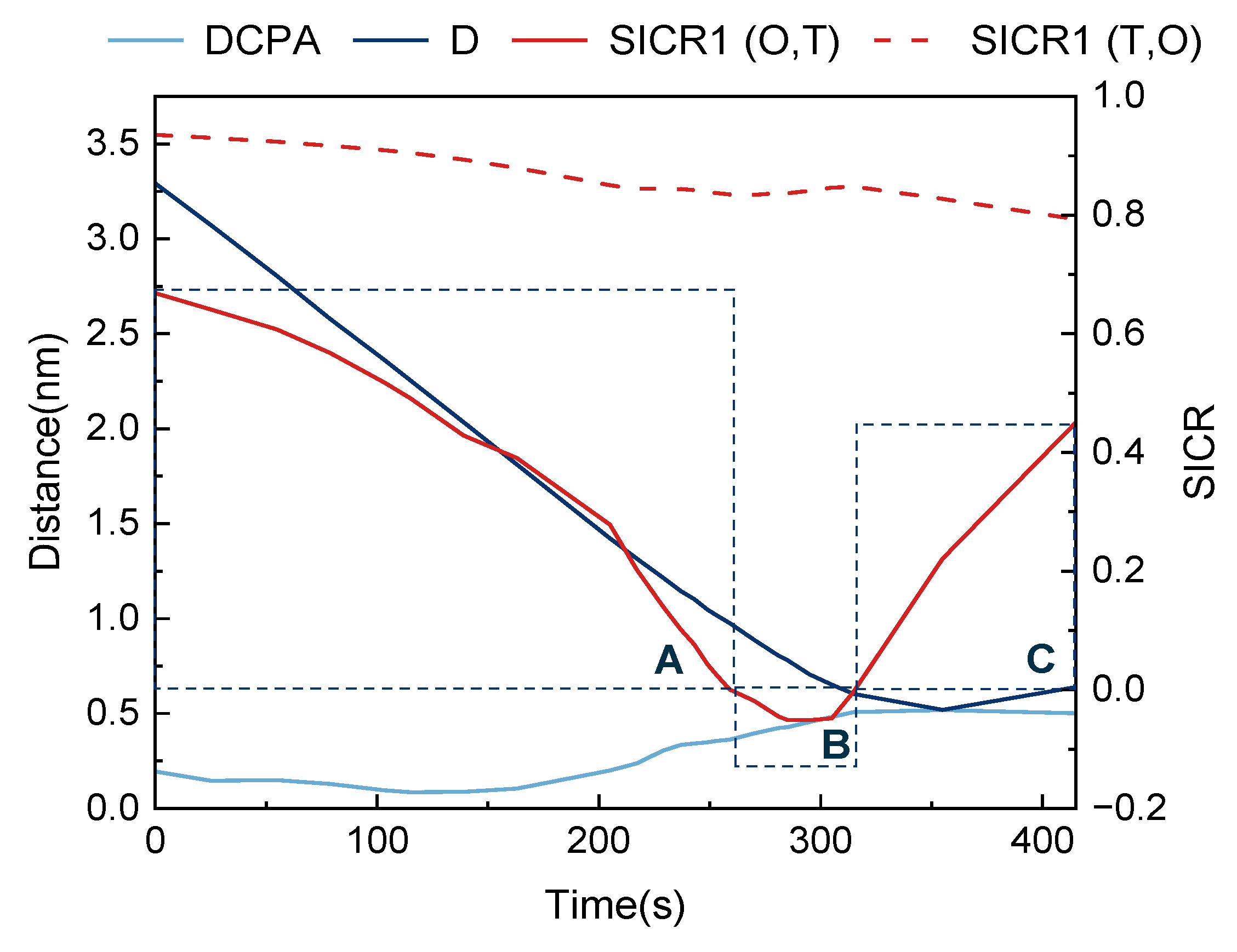
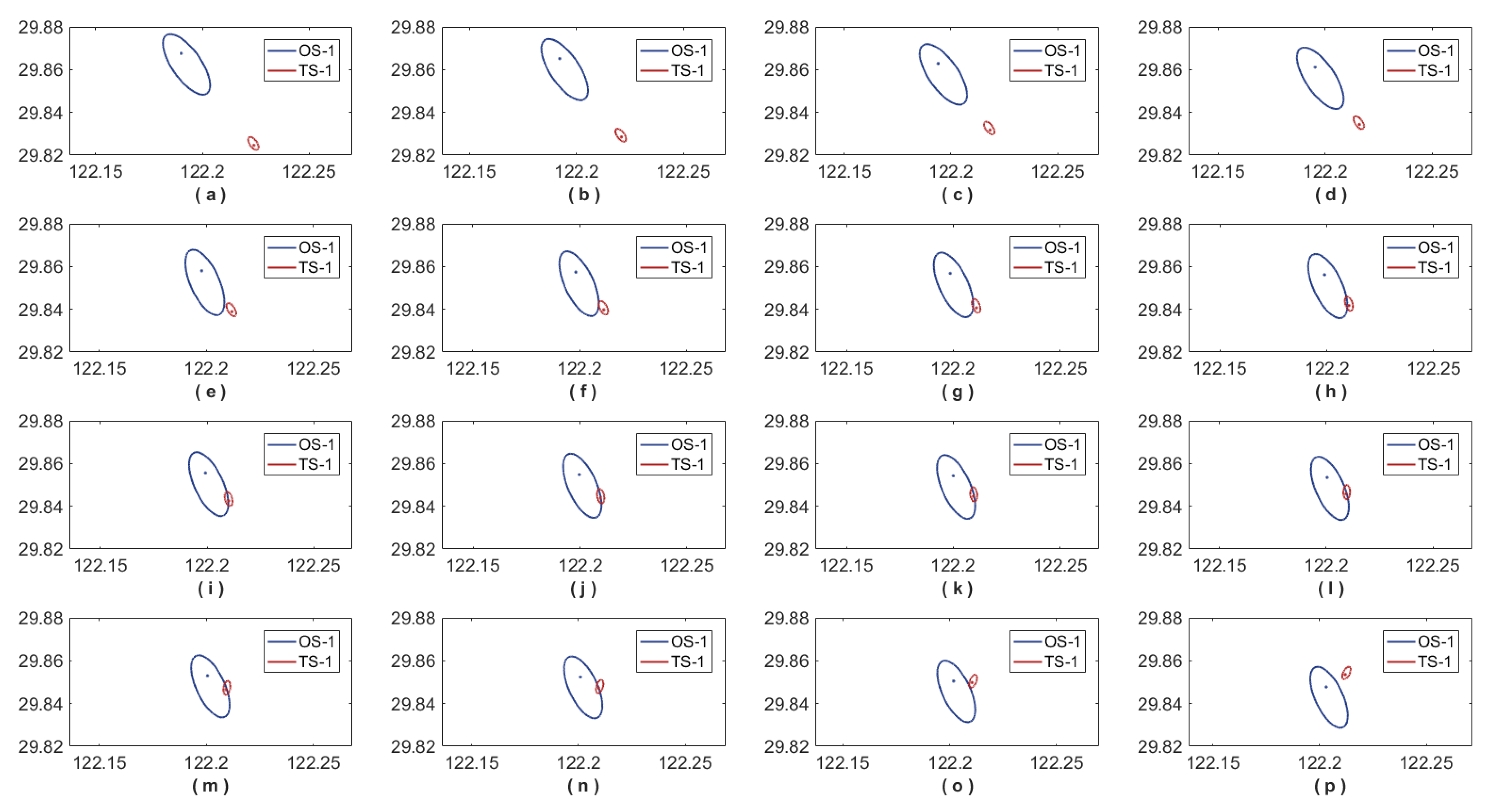
4.1. Head-On Encounter Situation

According to COLREGs, when two ships are at a collision risk in a head-on situation, they should turn to the right and pass each other on the port side. Figure 9 shows the actual head-on encounter situation between two ships based on their AIS data. The initial conditions are presented in Table 4. Figure 10 shows the variations in DCPA, D (i.e., the distance between the two ships), and the SICR. The red solid line segment represents the SICR1 (O, T) of TS-1 intruding into the OS-1 domain, and the red dotted line shows the SICR1 (T, O) of OS-1 intruding into the TS-1 domain. The SICR1 (O, T) is smaller than the SICR1 (O, T), so it was used to evaluate the collision risk in this scenario. The SICR1 (O, T) shows that the head-on encounter situation process can be divided into stages A, B, and C (shown as rectangles).
Figure 11 shows the changes in the relative positions of the two ships and their domains as well as the corresponding SICR1 (O, T) values for the head-on encounter situation as 16 subgraphs. In stages A (subgraphs a–i) and C (subgraphs o–p), TS-1 did not invade the domain of OS-1. In stage B (subgraphs j–n), TS-1 gradually invaded the domain of OS-1. In stage A, as the distance between the two ships gradually decreased, the SICR1 (O, T) gradually decreased from 0.669 to 0, at which point TS-1 invaded the ship domain of OS-1 (i.e., stage B). TS-1 then began to decelerate and turn to the right to avoid collision (subgraph f) when t = 163 s and the SICR1 (O, T) = 0.391. As the two ships came closer, TS-1 intruded further into the OS-1 domain. However, the collision avoidance actions of TS-1 slowed the decrease in the SICR1 (O, T) until the minimum value of SICR1 (O, T) = −0.051 was reached. TS-1 took action to leave the OS-1 domain (subgraph j), and the distance from OS-1 gradually increased with the SICR. In stage C, TS-1 continued to sail away from OS-1 until it was no longer in the OS-1 domain, and the SICR1 (O, T) gradually approached 1 as the distance between the two ships increased. The greatest intrusion of TS-1 into the OS-1 domain corresponded to the highest risk of collision.
Figure 10 shows that the collision avoidance actions of TS-1 resulted in relatively gentle changes in DCPA. This may cause difficulties with obtaining an early warning and may delay collision avoidance actions. The duration of the TS-1 intrusion into the OS-1 domain was short at 56 s, which is consistent with the characteristics of the encounter situation: a fast relative speed and short time for judging and avoiding collision. The timing of the action taken by TS-1 was consistent with the obtained values of the proposed SICR model.

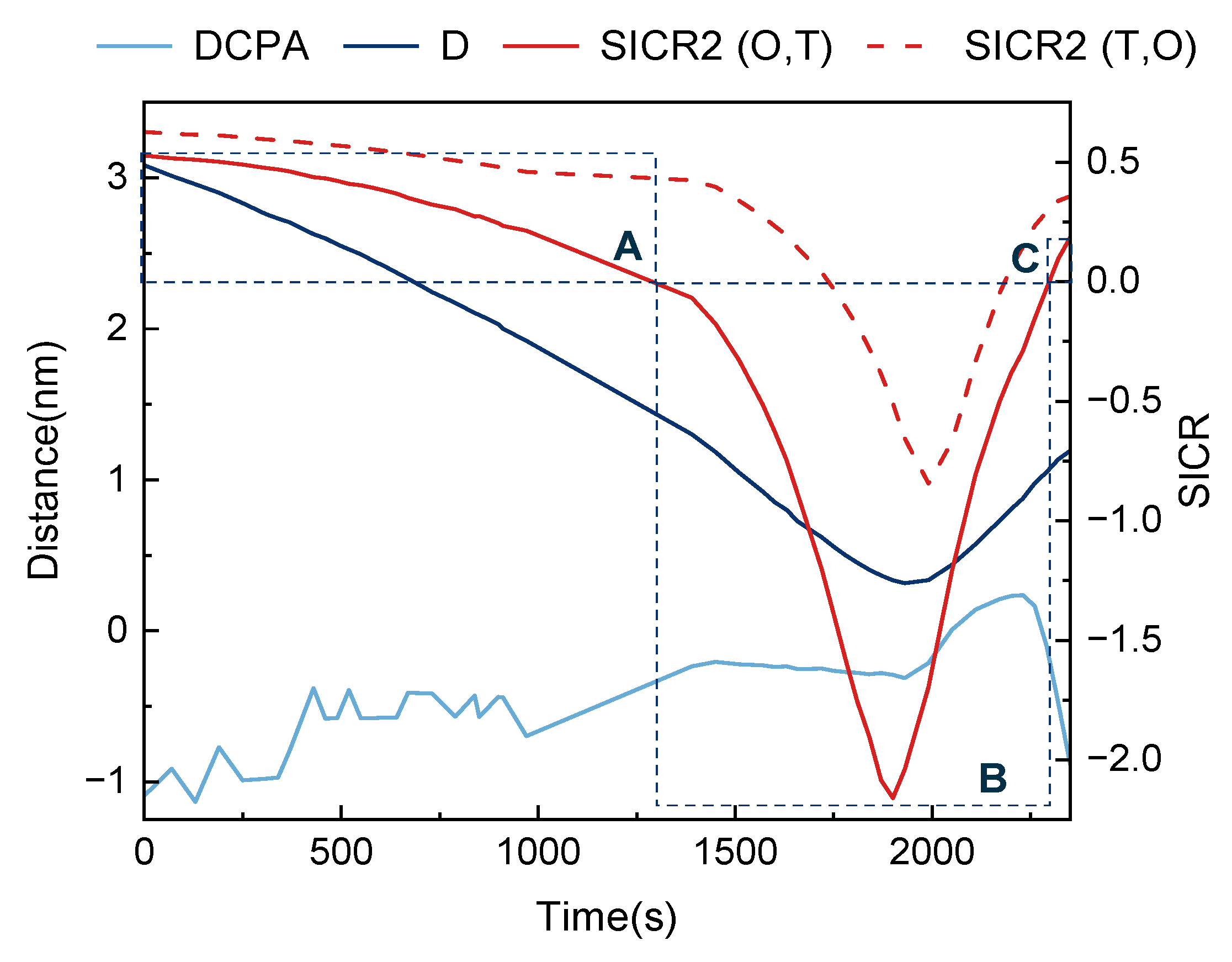
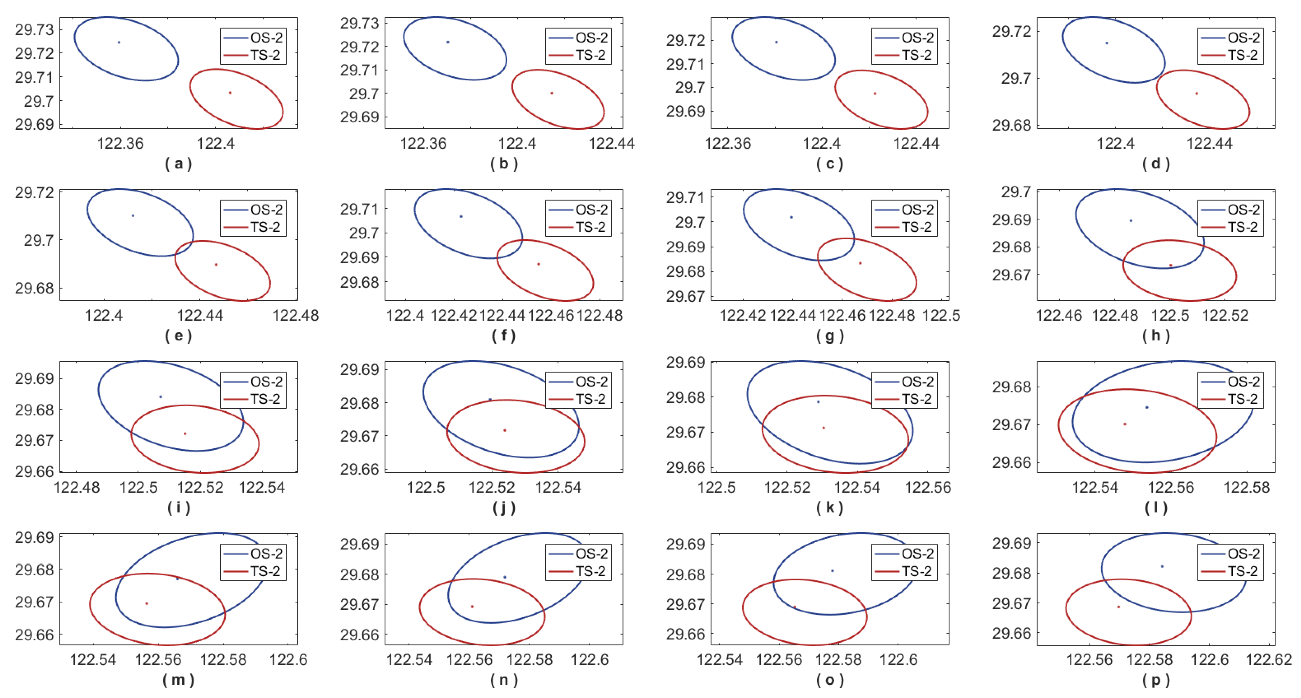
4.2. Overtaking Encounter Situation

In an overtaking encounter situation, COLREGs state that the overtaken ship should give way to the overtaking ship. Figure 12 shows the actual overtaking encounter situation of two ships at sea based on AIS data. OS-2 was the overtaking ship behind the overtaken ship TS-2.
Table 5 presents the initial time information of the two ships. Figure 13 shows the variations in the SICR values. The red solid line shows the SICR2 (O, T) of TS-2 entering the OS-2 domain, and the red dotted line shows the SICR2 (T, O) of OS-2 entering the TS-2 domain. The SICR2 (O, T) is smaller than the SICR2 (T, O), so it was used to evaluate the collision risk in this scenario. Figure 14 plots the changes in relative positions of the two ships as 16 subgraphs. In stages A (subgraphs a–g) and C (subgraph p), TS-2 did not invade the OS-2 domain. In stage B (subgraphs h–o), TS-2 gradually invaded the OS-2 domain. In an overtaking situation, the low relative speed between the two ships means that the distance between the two ships changed slowly. Thus, the SICR2 (O, T) decreased slowly from 0.528. At t = 250 s (SICR2 (O, T) = 0.489), OS-2 accelerated toward TS-2. In stage B, TS-2 invaded the ship domain of OS-2, which corresponded to a long parallel time, small transverse distance, and rapid change in the SICR2 (O, T). At t = 1900 s, the minimum value of SICR2 (O, T) = −2.159 was reached, after which TS-2 began to leave the OS-2 domain.
Figure 13 shows that the changes in DCPA during the collision avoidance actions of OS-2 were extremely unstable with large fluctuations, which may confuse a navigator trying to judge the collision risk. The low relative speed between the two ships means that the intrusion of TS-2 in the OS-2 domain was long at 1008 s. The timing of the actions taken by OS-2 were consistent with the values obtained by the proposed SICR model.

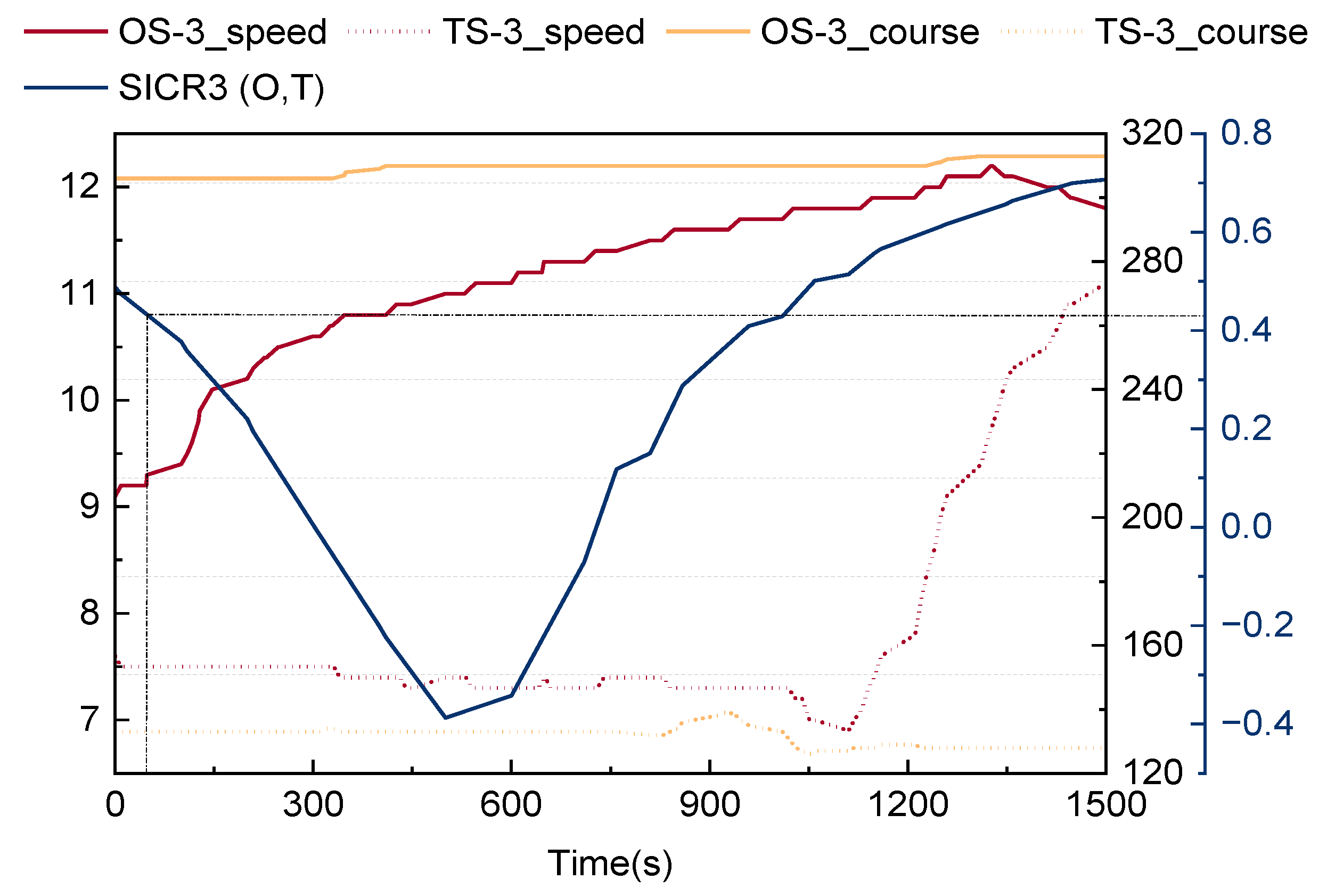
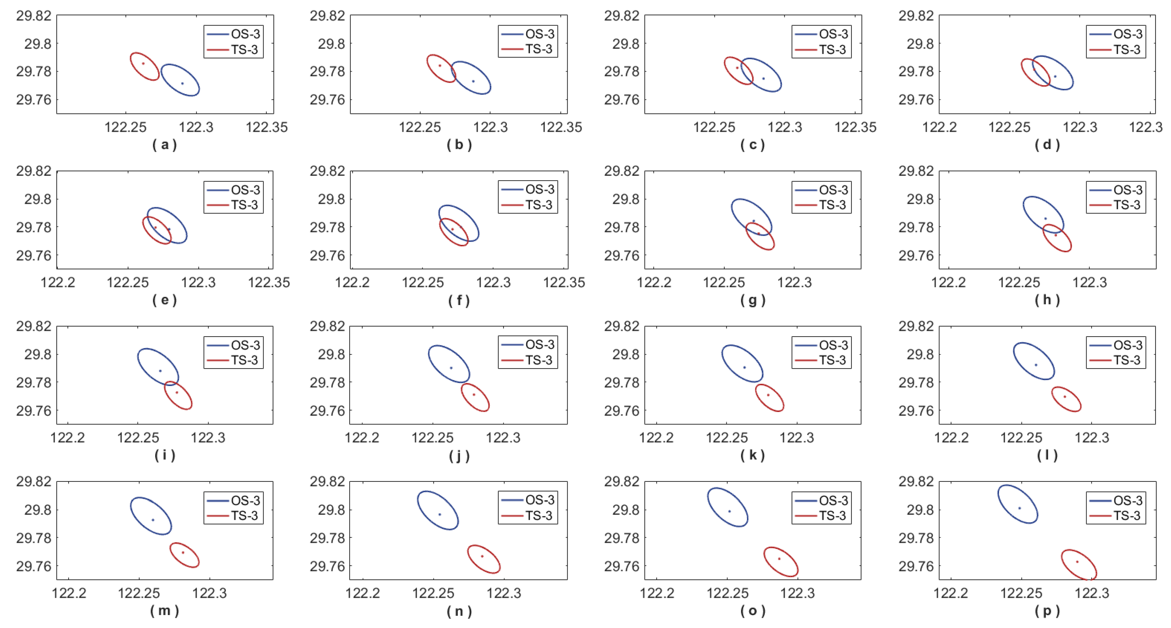
4.3. Crossing Encounter Situation

In a crossing encounter situation, COLREGs stipulate that a ship should give way to another ship on the starboard side. Figure 15 shows an actual crossing encounter situation where two ships crossed at a small angle. Based on the AIS data, OS-3 was on the starboard side of TS-3.
Figure 16 shows the calculated SICR values. The red solid line shows the SICR3 (O, T) of TS-3 entering the OS-3 domain, and the red dotted line shows the SICR3 (T, O) of OS-3 entering the TS-3 domain. The SICR3 (O, T) is smaller than the SICR3 (T, O), so it was used to evaluate the collision risk in this scenario. Figure 17 plots the changes in relative position of the two ships and their domains during the crossing encounter situation as 16 subgraphs. In stages A (subgraphs a–d) and C (subgraphs (h–p), TS-3 did not invade the OS-3 domain. In stage B (subgraphs e–g), TS-3 gradually invaded the OS-3 domain. In this situation, the high relative speed of the two ships meant that the two ships approached each other quickly. The SICR3 (O, T) decreased rapidly from 0.489. At t = 100 s and SICR3 (O, T) = 0.358, OS-3 accelerated to avoid collision. SICR3 (O, T) reached the minimum value of −0.387 at t = 500 s and then began to increase, which indicates that TS-3 began to leave the OS-3 domain.
Figure 16 shows that TS-3 taking collision avoidance actions resulted in relatively gentle changes to DCPA. Thus, it would be difficult to use DCPA to obtain an early warning in this situation, which can lead to delayed collision avoidance actions. The intrusion of TS-3 into the OS-3 domain lasted 426 s, which is between the durations for the head-on and overtaking scenarios. This is consistent with the characteristics of the crossing encounter situation. The collision avoidance actions taken by OS-3 corresponded with the values obtained by the proposed SICR model.

4.4. Case Simulation Discussion

This study proposes a SICR model based on the dynamic elliptical ship domain. We compared the SICR of ships in three encounter situations, that is, we compared the SICR curves in Figure 9, Figure 12, and Figure 15, as shown in Figure 18. It is found that in the head-on encounter situation, the value of the SICR1 (O, T) changes most rapidly and in a short time, which indicates that this situation is more dangerous than other situations. It also shows that the two ships approach at a faster relative speed in the field of dynamic ships. In the overtaking situation, the SICR2 (O, T) value changes more smoothly and lasts for a long time, indicating that the relative speed of the two ships is small and the parallel driving time is long. In the crossing encounter situation, the SICR3 (O, T) value is the gentlest, and the duration time is between the encounter and the overtaking scene. The change in the SICR value reflects the characteristics of the encounter situation, which is more accurate and reasonable than DCPA to judge the collision risk. However, one limitation of this model is that it does not consider the installation position of AIS equipment, which may cause a certain deviation when calculating the SICR. Although it is preliminary, the model can intuitively calculate the current collision risk of the ship, has better collision risk perception ability, reduces the subjective factors of the driver in judging the risk, and can be used to help the intelligent ship generate the timing of collision avoidance decision.

5. Conclusions

We developed an SICR model based on a dynamic elliptical ship domain and AIS data to facilitate collision avoidance between ships. The proposed model considers parameters such as the ship speed, course, and maneuverability and uses the degree of ship intrusion to quantify the collision risk. Simulations of the collision avoidance behavior in different encounter situations showed that the two ships should collaborate between SICR values of 0.5 and 0.6 to avoid collisions. Collision avoidance actions should be taken at SICR values between 0.3 and 0.5, depending on the encounter situation. We obtained the following conclusions:
  • Utilizing AIS data to optimize the dynamic elliptical ship domain meets the needs of algorithm calculation and visual display, which is convenient for rapid application in navigation collision avoidance practice.
  • The proposed SICR is more reasonable than the previous CRI because it is based on a dynamic elliptical ship domain driven by AIS data, and it fully considers the ship speed and maneuverability.
  • The SICR values of two ships in an encounter situation may differ because their differing maneuverability and speed affect the sizes of their individual domains, which in turn affect the safe distance. In this case, the smaller value between SICR (O, T) and SICR (T, O) at a given time can be used to measure the collision risk.
  • The SICR model can accurately detect the collision risk, and it can facilitate early warning of a collision risk. The simulation results indicated that ships can collaborate to avoid collisions at a minimum SICR of 0.5–0.6, and collision avoidance actions are most effective at SICR values of 0.3–0.5.
The proposed SICR model can help detect collision risks quickly and accurately, which can help improve navigation safety. However, some shortcomings still need to be addressed. Future research will involve optimizing the SICR model in the following aspects:
  • During the transmission of AIS data, the ship position is inevitably affected by wind, waves, and currents. This generates offsets in the speed and position of the ship, which introduces some error in the SICR calculation.
  • Existing ship track prediction models have low prediction accuracy and a lack of real-time prediction capability. We are developing an online multioutput least squares support vector machine (SM-OMLSSVR) ship track prediction model based on AIS data and a selection mechanism. The AIS data of TSs with a potential collision risk are obtained in real time, and the TS track is predicted to assist the OS with evaluating the collision risk.

Author Contributions

Methodology, W.L. and L.Z.; software, W.L.; validation, W.L. and L.Z.; writing—original draft preparation, W.L., L.Z. and Y.L.; writing—review and editing, W.L. and L.Z.; supervision, W.L. and G.S. All authors have read and agreed to the published version of the manuscript.

Funding

This research was funded by the Fundamental Research Funds for the Central Universities, under funding number 3132023153 and 3132023154.

Institutional Review Board Statement

Not applicable.

Informed Consent Statement

Not applicable.

Data Availability Statement

The data that support the findings of this study are available within this article.

Conflicts of Interest

The authors declare no conflict of interest.

Abbreviations

AbbreviationMeaning
AISAutomatic Identification System
COLREGsInternational Regulations for Preventing Collisions at Sea
CRICollision Risk Index
DBSCANDensity-Based Spatial Clustering of Applications with Noise
DCPADistance at the closest point of approach
IMOInternational Maritime Organization
MMSIMaritime Mobile Service Identity
OSOwn ship
OS-1Own ship in the head-on situation
OS-2Own ship in the overtaking situation
OS-3Own ship in the crossing situation
SICRShip Intrusion Collision Risk
SICR (O, T)Ship Intrusion Collision Risk of the TS entering the OS domain
SICR (T, O)Ship Intrusion Collision Risk of the OS entering the TS domain
SICR1 (O, T)Ship Intrusion Collision Risk of the TS entering the OS domain in the head-on situation
SICR1 (T, O)Ship Intrusion Collision Risk of the OS entering the TS domain in the head-on situation
SICR2 (O, T)Ship Intrusion Collision Risk of the TS entering the OS domain in the overtaking situation
SICR2 (T, O)Ship Intrusion Collision Risk of the OS entering the TS domain in the overtaking situation
SICR3 (O, T)Ship Intrusion Collision Risk of the TS entering the OS domain in the crossing situation
SICR3 (T, O)Ship Intrusion Collision Risk of the OS entering the TS domain in the crossing situation
SM-OMLSSVROnline Multioutput Least Squares Support Vector Machine based on Selection Mechanism
TCPATime at the closest point of approach
TSTarget Ship
TS-1Target Ship in the head-on situation
TS-2Target Ship in the overtaking situation
TS-3Target Ship in the crossing situation

References

  1. International Maritime Organization. Review of Maritime Transport 2019; IMO: London, UK, 2019. [Google Scholar]
  2. Agency EMS. European Maritime Safety Report 2022; Publications Office of the European Union: Luxembourg, 2022. [Google Scholar]
  3. Rong, H.; Teixeira, A.P.; Soares, C.G. Spatial correlation analysis of near ship collision hotspots with local maritime traffic characteristics. Reliab. Eng. Syst. Saf. 2021, 209, 107463. [Google Scholar] [CrossRef]
  4. Yuhong, L.; Hongbo, C.; Yanling, H. A Risk-Degree Model of Collision Based on Fuzzy Theory. Navig. China 1998, 2, 25–31. [Google Scholar]
  5. Shu, W.; Meng-Hong, Y.U. Development of Collision Avoidance System by Using Expert System and Search Algorithm. Ship Ence Technol. 2007, 48, 197–212. [Google Scholar]
  6. Zhen, R.; Riveiro, M.; Jin, Y. A novel analytic framework of real-time multi-vessel collision risk assessment for maritime traffic surveillance. Ocean Eng. 2017, 145, 492–501. [Google Scholar] [CrossRef]
  7. Chen, P.; Li, M.; Mou, J. A Velocity Obstacle-Based Real-Time Regional Ship Collision Risk Analysis Method. J. Mar Sci Eng 2021, 9, 428. [Google Scholar] [CrossRef]
  8. Huang, Y.; van Gelder, P.H.A.J. Collision risk measure for triggering evasive actions of maritime autonomous surface ships. Safety Sci. 2020, 127, 104708. [Google Scholar] [CrossRef]
  9. Liu, Y.; Ma, Y. A Field Theory-Based Novel Algorithm for Navigational Hazard Index. J. Mar. Sci. Eng. 2023, 11, 178. [Google Scholar] [CrossRef]
  10. Fujii, Y.; Shiobara, R. The Analysis of Traffic Accidents. J. Navig. 1971, 24, 534–543. [Google Scholar] [CrossRef]
  11. Szlapczynski, R.; Szlapczynska, J. Review of ship safety domains: Models and applications. Ocean Eng. 2017, 145, 277–289. [Google Scholar] [CrossRef]
  12. Goodwin, E.M. A Statistical Study of Ship Domains. J. Navig. 1975, 28, 328–344. [Google Scholar] [CrossRef]
  13. Coldwell, T.G. Marine Traffic Behaviour in Restricted Waters. J. Navig. 1983, 36, 430–444. [Google Scholar] [CrossRef]
  14. Hansen, M.G.; Jensen, T.K.; Lehn-Schiøler, T.; Melchild, K.; Rasmussen, F.M.; Ennemark, F. Empirical Ship Domain based on AIS Data. J. Navig. 2013, 66, 931–940. [Google Scholar] [CrossRef]
  15. Iperen, E.V. Classifying Ship Encounters to Monitor Traffic Safety on the North Sea from AIS Data. Transnav Int. J. Mar. Navig. Saf. Sea Transp. 2015, 9, 51–58. [Google Scholar] [CrossRef]
  16. Sun, L. The Research on Mathematic Models of Decision-Making in Ship Collision Avoidance. Ph.D. Thesis, Dalian Maritime University, Dalian, China, 2000. [Google Scholar]
  17. Liu, S. The Research of the Inland River Channel Transit Capacity Where Ship Is Crowed. Master’s Thesis, Dalian Maritime University, Dalian, China, 2002. [Google Scholar]
  18. Pietrzykowski, Z.; Uriasz, J. The Ship Domain—A Criterion of Navigational Safety Assessment in an Open Sea Area. J. Navig. 2009, 62, 93–108. [Google Scholar] [CrossRef]
  19. Pietrzykowski, Z. Ship’s Fuzzy Domain: A Criterion for Navigational Safety in Narrow Fairways. J. Navig. 2008, 61, 499–514. [Google Scholar] [CrossRef]
  20. Zhu, X.; Xu, H.; Lin, J. Domain and Its Model Based on Neural Networks. J. Navig. 2001, 54, 97–103. [Google Scholar] [CrossRef]
  21. Wang, N. An intelligent spatial collision risk based on the quaternion ship domain. J. Navig. 2010, 63, 733–749. [Google Scholar] [CrossRef]
  22. Wang, N. A novel analytical framework for dynamic quaternion ship domains. J. Navig. 2013, 66, 265–281. [Google Scholar] [CrossRef]
  23. Wang, S.; Zhang, Y.; Huo, R.; Mao, W. A real-time ship collision risk perception model derived from domain-based approach parameters. Ocean Eng. 2022, 265, 112554. [Google Scholar] [CrossRef]
  24. Szlapczynski, R.; Szlapczynska, J. An analysis of domain-based ship collision risk parameters. Ocean Eng. 2016, 126, 47–56. [Google Scholar] [CrossRef]
  25. Liu, J.; Shi, G.; Zhu, K. A novel ship collision risk evaluation algorithm based on the maximum interval of two ship domains and the violation degree of two ship domains. Ocean Eng. 2022, 255, 111431. [Google Scholar] [CrossRef]
  26. Yuan, X.; Zhang, D.; Zhang, J.; Zhang, M.; Soares, C.G. A novel real-time collision risk awareness method based on velocity obstacle considering uncertainties in ship dynamics. Ocean Eng. 2020, 220, 108436. [Google Scholar] [CrossRef]
  27. Li, W.; Zhong, L.; Xu, Y.; Shi, G. Collision Risk Index Calculation Based on an Improved Ship Domain Model. J. Mar. Sci. Eng. 2022, 10, 2016. [Google Scholar] [CrossRef]
  28. Smierzchalski, R.; Michalewicz, Z. Modeling of ship trajectory in collision situations by an evolutionary algorithm. IEEE Trans. Evolut. Comput. 2000, 4, 227–241. [Google Scholar] [CrossRef]
  29. Wielgosz, M.; Pietrzykowski, Z. Ship domain in the restricted area—Analysis of the influence of ship speed on the shape and size of the domain. Chin. J. Clin. Neurosurg. 2012, 36, 514. [Google Scholar] [CrossRef]
  30. Wang, Y.; Chin, H.C. An Empirically-Calibrated Ship Domain as a Safety Criterion for Navigation in Confined Waters. J. Navig. 2016, 69, 257–276. [Google Scholar] [CrossRef]
  31. Zhou, D.; Zheng, Z. Dynamic Fuzzy Ship Domain Considering the Factors of Own Ship and Other Ships. J. Navig. 2019, 72, 467–482. [Google Scholar] [CrossRef]
  32. Pietrzykowski, Z.; Wielgosz, M. Effective ship domain—Impact of ship size and speed. Ocean Eng. 2021, 219, 108423. [Google Scholar] [CrossRef]
  33. Kijima, K.; Furukawa, Y. Automatic collision avoidance system using the concept of blocking area. IFAC Proc. Vol. 2003, 36, 223–228. [Google Scholar] [CrossRef]
  34. Pallotta, G.; Vespe, M.; Bryan, K. Vessel Pattern Knowledge Discovery from AIS Data: A Framework for Anomaly Detection and Route Prediction. Entropy 2013, 15, 2218–2245. [Google Scholar] [CrossRef]
  35. Aarsæther, K.G.; Moan, T. Estimating navigation patterns from AIS. J. Navig. 2009, 62, 587–607. [Google Scholar] [CrossRef]
  36. Zhang, W.; Goerlandt, F.; Kujala, P.; Wang, Y. An advanced method for detecting possible near miss ship collisions from AIS data. Ocean Eng. 2016, 124, 141–156. [Google Scholar] [CrossRef]
Figure 1. Dynamic elliptical ship domain.
Jmse 11 01122 g001
Figure 2. Dynamic elliptical ship domain in different encounter situations: (a) head-on, (b) overtaking, and (c) crossing.
Jmse 11 01122 g002
Figure 3. Dynamic elliptical ship domain in the ground coordinate system.
Jmse 11 01122 g003
Figure 4. Different domain-based safety criteria: (a) the OS domain should not be invaded by the TS; (b) the TS domain should not be invaded by the OS; (c) neither the OS nor TS should invade each other’s domain; (d) the OS and TS domains should not overlap.
Jmse 11 01122 g004
Figure 5. Comparison among the three ship domains.
Jmse 11 01122 g005
Figure 6. Positions of the OS and the TS in the crossing situation.
Jmse 11 01122 g006
Figure 7. Diagram of the TS relative to the center of the elliptical dynamic ship domain for the OS.
Jmse 11 01122 g007
Figure 8. Variation in the SICR of two ships in the head-on encounter situation.
Jmse 11 01122 g008
Figure 9. Variations in the speed, course, and SICR of two ships in the head-on situation.
Jmse 11 01122 g009
Figure 10. Variations in DCPA, D, and SICR of two ships in the head-on situation.
Jmse 11 01122 g010
Figure 11. Relative positions of two ships in the head-on situation, (ap) are the subgraph of the positions of the two ships at different times in the head-on situation.
Jmse 11 01122 g011
Figure 12. Variations in the speed, course, and SICR of two ships in the overtaking situation.
Jmse 11 01122 g012
Figure 13. Variations in DCPA, D, and SICR of two ships in the overtaking situation.
Jmse 11 01122 g013
Figure 14. Relative positions of two ships in the overtaking situation, (ap) are the subgraph of the positions of the two ships at different times in the overtaking situation.
Jmse 11 01122 g014
Figure 15. Variations in the speed, course, and SICR of two ships in the crossing situation.
Jmse 11 01122 g015
Figure 16. Variations in DCPA, D, and SICR of two ships in the crossing situation.
Jmse 11 01122 g016
Figure 17. Relative positions of two ships in the crossing situation, (ap) are the subgraph of the positions of the two ships at different times in the crossing situation.
Jmse 11 01122 g017
Figure 18. Comparing the SICR of ships in three encounter situations.
Jmse 11 01122 g018
Table 1. Representative ship domains.
TypeReferenceInfluencing Factors
Static domain models[10]OS size, TS size, Weather conditions
[12]Weather conditions, COLREGs
[13]OS size, Encounter situations, COLREGs
[18]OS size, speed, and maneuverability; Weather conditions; Traffic conditions
[24]OS size
Dynamic domain models[28]OS speed and maneuverability
[29]OS size and speed
[30]OS size and speed, TS size and speed, COLREGs
[27]OS size, speed, and maneuverability; TS size, speed, and maneuverability; Encounter situations; COLREGs
Fuzzy boundary domain models[21,22]OS size, speed, and maneuverability; Weather conditions; COLREGs
[31]Distance of TSs to OS in different directions
[32]OS size, speed, and maneuverability; Encounter situations; Weather conditions; Traffic conditions
Table 2. Basic parameters of YUPENG and YUKUN.
ParametersYUPENG (OS)YUKUN (TS)
MMSI412212110412701000
Length overall (m)199.8116
Breadth (m)27.818
Depth (m)15.58.35
Displacement (T)22,036.75735.5
Design draft (m)10.35.4
Table 3. Initial information of YUPENG and YUKUN in the head-on encounter situation.
NameShip Position
(Relative to Nautical Miles)
Course
(°)
Speed
(kn)
YUPENG (OS)(−5.7, −0.26)08617
YUKUN (TS)(−1.5, 0)27015
Table 4. Initial ship information in the head-on encounter situation.
MMSIShip PositionCourse
(°)
Speed
(kn)
Length
(m)
OS-1210302000(29°52.056′ N, 122°11.406′ E)14512.2225
TS-1355384000(29°49.476′ N, 122°13.451′ E)32519.145
Table 5. Initial ship information in the overtaking encounter situation.
MMSIShip PositionCourse
(°)
Speed
(kn)
Length
(m)
OS-2209251000(29°43.474′ N, 122°21.564′ E)10816.9337
TS-2235069077(29°41.199′ N, 122°24.372′ E)11213.3340
Table 6. Initial ship information in the crossing encounter situation.
MMSIShip PositionCourse
(°)
Speed
(kn)
Length
(m)
OS-3219080000(29°46.283′ N, 122°17.418′ E)3069.1300
TS-3355384000(29°47.133′ N, 122°15.747′ E)1337.6260
Disclaimer/Publisher’s Note: The statements, opinions and data contained in all publications are solely those of the individual author(s) and contributor(s) and not of MDPI and/or the editor(s). MDPI and/or the editor(s) disclaim responsibility for any injury to people or property resulting from any ideas, methods, instructions or products referred to in the content.

