Article

Underwater Image Restoration Method Based on Multi-Frame Image under Artificial Light Source

1
College of Information Science and Engineering, Chongqing Jiaotong University, Chongqing 400074, China
2
College of Mechanical and Electrical Engineering, Harbin Engineering University, Harbin 150009, China
*
Author to whom correspondence should be addressed.
J. Mar. Sci. Eng. 2023, 11(6), 1213; https://doi.org/10.3390/jmse11061213
Submission received: 18 May 2023 / Revised: 4 June 2023 / Accepted: 9 June 2023 / Published: 12 June 2023
(This article belongs to the Section Physical Oceanography)

Abstract

:
This paper studies the underwater image restoration problem in autonomous operation of AUV guided by underwater visual. An improved underwater image restoration method is developed based on multi-frame neighboring images under artificial light source. At first, multi-frame neighboring images are collected during AUV approaching the targets, and a transmittance estimation method is developed based on the multi-frame images to avoid the assumption of the known normalized residual energy ratio in the traditional methods. Then, the foreground and background regions of the images are segmented by locking the small area where the background light is located. Hence, the accuracy of background light estimation is improved for the underwater mages in turbid water to improve the accuracy of image restoration. Finally, the performance of the developed underwater image restoration method is verified by the comparative results in the pool environment.

1. Introduction

Due to the advantages of good maneuverability and wide operation range, AUV (Autonomous Underwater Vehicle) has been widely used in underwater target detection and other tasks [1]. There are mainly two types of underwater target detection methods, hydroacoustic and optical vision [2]. The hydroacoustic method is suitable for the detection of long-distance and large targets [3], while the optical vision method is suitable for the detection of close-range and small targets [4]. Since optical vision has the characteristics of high image resolution and rich information, it is the main means to obtain target information during close operation of AUV [5]. Thus, optical vision has been widely used in AUV-based submarine pipeline monitoring and underwater salvage operations [6,7]. This paper focuses on underwater optical vision to capture spherical objects at close range.
Due to the scattering, attenuation and other characteristics of light propagation in water, the visual image in water has certain problems, such as blurred image, overall fog mask and color cast [8]. Thus, image processing is required to obtain a clearer image [9]. There are two main methods for underwater image clarity, including image enhancement and image restoration [10]. The image enhancement method mainly reduces underwater image noise and strengthens the characteristics of the object of interest, but the physical process of underwater image quality degradation is not considered [11,12]. In the image restoration method, the image quality degradation process is derived backwards based on underwater imaging model and some compensations are added accordingly [13,14]. Underwater image restoration method is the topic of this paper.
The performance of underwater image restoration is closely related to the light source. In the past, underwater image processing was mostly aimed at underwater images taken close to the water surface under the solar light source, or the solar light source was the main light source. AUV generally works in a water with several hundred meters depth, where there is no sunlight and the artificial light source (illuminator) is the only light source. Artificial light sources have different lighting directions than sun sources. The solar light source shines on the target from top to bottom. The artificial light source is fixed on the AUV and irradiates horizontally to the target. The characteristics of the visual image obtained by different light source directions are also different [15,16]. The modeling, detection and compensation of artificial light sources is relatively new to underwater image processing, and there is no universally applicable method, which has become a research hotspot and also a point of difficulty in recent years [17,18].
Dark channel prior was proposed for image restoration in [19], which has a very good effect on land image defogging. DCP has received widespread attention, and has also become one of the important methods in underwater image restoration [20,21,22]. Authors of Ref. [23] presented underwater dark channel prior (UDCP) for underwater single images, but this method only uses DCP in the blue and green channels, resulting in color casts in the restored image. Carlevaris [24] proposed an underwater image restoration method based on maximum intensity prior (MIP), where the depth of field value is estimated by the maximum intensity difference. However, the image restoration effect is greatly affected by the underwater lighting conditions. Another underwater image restoration method was developed based on wavelength compensation and dehazing model (WCID) [17], where some assumptions were required, for example, the normalized residual energy ratio is known and the attenuation factor can be obtained empirically. In [18], an underwater scene depth estimation method proposed based on image blurriness and light absorption (IBLA) to reduce the influence of the lighting conditions. In [25], a new scene depth estimation method was proposed based on the different attenuation laws under different wavelengths of light, which avoided that the pixels of white objects in the artificial lighting area may be incorrectly estimated as background light. The above references are aimed at the underwater image restoration for near the water surface where both sunlight and artificial light source exist, and their basic idea is to use the solar light source as the main light source to remove/reduce the influence of artificial light source.
There are a few research about the underwater image processing in deep sea with only artificial light source. For example, Ref. [26] proposed deep sea image enhancement method under artificial light alone based on the active illumination, and the performance is good when the quality of original images is good. However, the water quality in this paper is very turbid with many impurities, and the original image quality is poor. A two-stage underwater image restoration algorithm was proposed based on a physical model and causal intervention in [27], which effectively solves the problem of underwater image degradation. A rapid deep-sea image restoration algorithm was applied to unmanned underwater vehicles in [28], which has good results in terms of image restoration results, validity, quality, and real-time performance.
From the above-mentioned references, we can infer that underwater image processing research is aimed at solar sources or the combined effect of solar source and artificial light source, while there are a few studies on underwater image restoration under artificial light source.
This paper investigates underwater image restoration with only artificial light source for AUV operation guided by visual images. The main contributions of this paper are presented as follows.
(1)
An improved underwater image restoration method is developed based on multi-frame neighboring images under artificial light source.
(2)
To address the limitations of the traditional image restoration methods where the normalized residual energy ratio should be known a priori and the attenuation coefficient is difficult to be adjusted, a transmittance estimation method is developed based on the multi-frame images. Specifically, the attenuation coefficient is calculated using the light intensity attenuation relationship of corresponding points between multiple frame sequence images.
(3)
There is significant deviation or even failure in the estimation of background light under artificial light sources in turbid water bodies based on the existing methods. To solve the problem, this paper presents a new background light estimation method. By segmenting the foreground and background regions of underwater images under artificial light sources, the accuracy of background light estimation in turbid water bodies is improved by locking the small area where the background light is located. Therefore, the accuracy of image restoration is improved.
(4)
The developed method and some existing methods are used to restore the underwater images. The comparative results demonstrate the effectiveness of the developed method under artificial light source.

2. Transmittance Estimation under Artificial Light Source

According to Ref. [17], the underwater image can be restored to be clear based on the following equation.
I λ x = J λ x t λ x + B λ 1 t λ x
where, I λ x is the original image; J λ x is the clear image obtained after image restoration; B λ represents background light; and t λ x is the transmittance.
The accuracy of the transmittance ( t λ x ) and the background light ( B λ ) has great influences on the restored performance of underwater images. This paper will focus on the determination of the two parameters. This section will present an improved method to improve the accuracy of the transmittance estimation.

2.1. Ideas of the Improved Transmittance Estimation

Aiming at the problem of image restoration in turbid water environment under artificial light source, a new transmittance estimation method is developed based on multi-frame images. Multi-frame sequence images are acquired during the AUV approaching the target. Firstly, the attenuation relationship of the light intensity at the corresponding points between multi-frame sequence images is used to solve the attenuation coefficient of light, denoted as c λ . Then, the depth estimation method based on image saturation is used to estimate the scene depth, denoted as d ( x ) . Finally, according to the attenuation coefficient c λ and scene depth of an image d x , the transmittance t λ ( x ) can be obtained.
In addition to the wavelength of light, the attenuation coefficient c λ is also affected by the salinity of seawater and the concentration of phytoplankton. At present, most research give an empirical value of the attenuation coefficient c λ according to the type of marine environment. However, it is difficult to obtain a suitable empirical value. In the developed method, the attenuation coefficient c λ is obtained via the multi-frame sequence images.

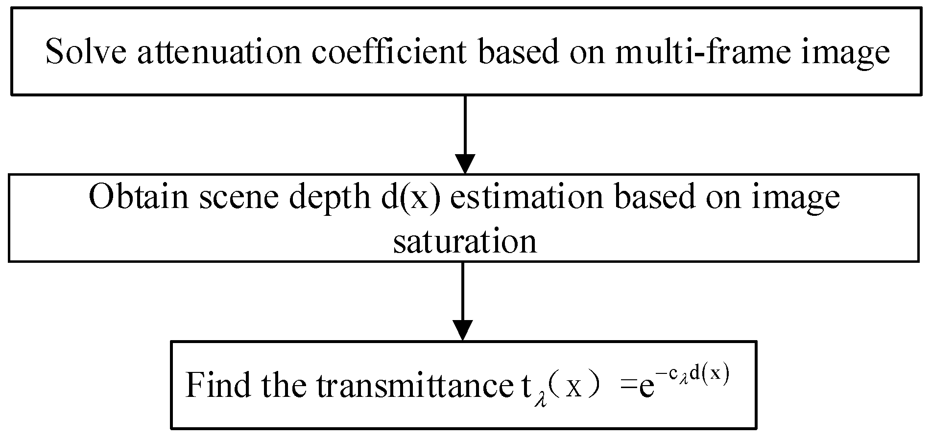
2.2. Specific Implementation of the Improved Transmittance Estimation

Based on the above ideas, the flow of the transmission estimation method in this paper is designed as shown in Figure 1.
According to Figure 1, the specific implementation is described below.
  • Step 1: Calculate attenuation coefficient c λ
Underwater imaging model [17]:
E λ , d x B λ 1 e c λ d = E λ , 0 x e c λ d
where, E λ , d x is the light intensity received by the camera d away from the target; x is the coordinates of a point in the scene, x = x , y ; E λ , 0 x is expressed as the light intensity at a point x on the target; and λ = { r , g , b } .
During the AUV approaching the target from far to near, two of the images are collected, and the equation is as follows:
E λ , d 1 x 1 B λ 1 1 e c λ d 1 = E λ , 1 x 1 e c λ d 1 E λ , d 2 x 2 B λ 2 1 e c λ d 2 = E λ , 2 x 2 e c λ d 2
where, E λ , d 1 x , and E λ , d 2 x are respectively expressed as the light intensity received by the camera d 1 and d 2 away from the target; B λ 1 , and B λ 2 are the corresponding background light; E λ , 1 x 1 , and E λ , 2 x 2 are the light intensity at the corresponding point x on the target in the image.
Taking logarithm of Equation (3), we can get:
ln E λ , d 1 x 1 B λ 1 1 e c λ d 1 = ln E λ , 1 x 1 c λ d 1 ln E λ , d 2 x 2 B λ 2 1 e c λ d 2 = ln E λ , 2 x 2 c λ d 2
The difference between the two equations in Equation (4) can be obtained:
ln E λ , d 1 x B λ 1 1 e c λ d 1 ln E λ , d 2 x B λ 2 1 e c λ d 2 = ln E λ , 1 x E λ , 2 x + c λ d 2 d 1
where, for the artificial light source configured in this paper, E λ , 1 x 1 , E λ , 2 x 2 is the light intensity reflected from the same point x on the target in the distance d 1 and d 2 images. Let the light intensity emitted by the artificial light source be E λ , 0 , then:
E λ , 1 x = E λ , 0 e c λ d 1 ρ λ , E λ , 2 x = E λ , 0 e c λ d 2 ρ λ
where, ρ λ represents the reflectivity of the target surface.
Take Equation (6) into Equation (5) to yield,
ln E λ , d 1 x B λ 1 1 e c λ d 1 ln E λ , d 2 x B λ 2 1 e c λ d 2 = 2 c λ d 2 d 1
In Equation (7), d 1 , and d 2 can be measured and calculated via Doppler Velocity Log (DVL) configured on AUV. E λ , d 1 x , and E λ , d 2 x are respectively expressed as the light intensity received by the camera d 1 and d 2 away from the target, and can be measured. Background lights B λ 1 and B λ 2 are calculated in below section. Therefore, the attenuation coefficient c λ is obtained.
  • Step 2: Scene depth estimation
When the underwater target is illuminated by the horizontal direction of the artificial light source, the light source intensity in the foreground area of the image is too strong, which increases the white light in the area and decrease the saturation. When the distance between the target and the AUV is increased, the effect of the artificial light source becomes weaker, and the saturation of the corresponding area gradually increases. Therefore, the relationship between image saturation and distance can be used to estimate the depth of field of the underwater image.
Image local saturation S ( x ) [29]:
S x = 1 3 m i n R x , G x , B x R x + G x + B x
where, R x , G x , B x are the intensity values of corresponding points in RGB three channels at point x.
The above image saturation can only reflect the relative distance between the nearest point and the farthest point in the underwater image scene. In order to convert the relative distance between points in the underwater image into absolute distance, it is necessary to define the actual distance of the nearest point in the image. In the actual operation of AUV, the distance d 0 between AUV and target can be calculated by DVL equipped in the AUV itself, so scene depth d ( x ) can be obtained as,
d x = D × S x + d 0
where, D is the conversion coefficient. Referring to Ref. [18] and comparing the experimental results of underwater images in this paper, D is taken as 9 in this paper.
  • Step 3: Transmission estimation
After attenuation coefficient c λ and scene depth d ( x ) , the transmittance t λ x can be obtained according to the following equation.
t λ x = e c λ d ( x )

3. Background Light Estimation under Artificial Light Source

Aiming at the restoration of underwater images with turbid water quality and artificial light source, this paper proposes a new method of background light estimation for underwater image restoration.

3.1. Ideas of Background Light Estimation

The light direction of artificial light source and solar light source is different, resulting in different image characteristics under the two light sources. The brightness of the foreground (target) of the underwater image under the solar light source is smaller than the background. This law is opposite under the artificial light source. Therefore, the background light estimation method under solar light source cannot be directly applied to estimate the background light of underwater image restoration with artificial light source. The foreground and background should be distinguished first, and then the background light should be estimated in the background.
For the underwater in turbid water, the effect of this method in [26] is very unsatisfactory to distinguish foreground and background. We can use the object segmentation to distinguish foreground and background.
Aiming at the target image segmentation, the image segmentation method based on YCbCr color space is a good choice for the images in turbid water under artificial light. It can effectively reduce the influence of scattering effect caused by suspended solids in turbid water on underwater background area segmentation of artificial light source. Please note: YCbCr is a kind of color space, where Y refers to the brightness component; Cb refers to the blue chromaticity component; and Cr refers to the red chromaticity component.
Therefore, the image segmentation method based on YCbCr color space is used to segment the foreground and background regions. Then, the quadtree method is used to further reduce the background area, and the small area corresponding to the background light is locked. Finally, the background light is estimated in the small area.

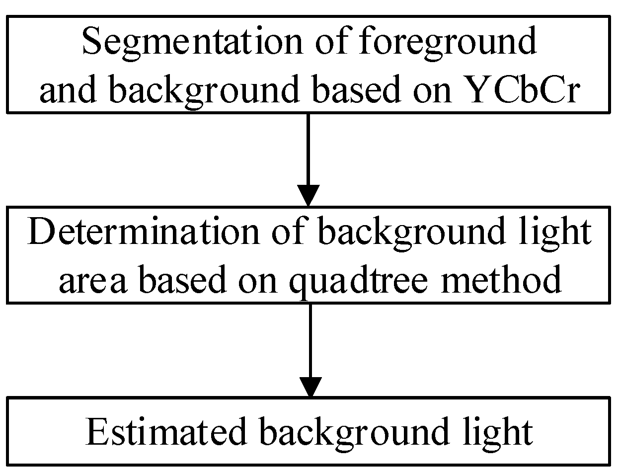
3.2. Specific Implementation of Background Light Estimation

Based on the above ideas, the flow of the background light estimation method in this paper is shown in Figure 2.
According to Figure 2, the specific implementation steps are as follows:
  • Step 1: Segmentation of foreground and background based on YCbCr
(1). Color space conversion.
The input image was converted from RGB color space to YCbCr color space according to the method in [29], and the conversion relationship is shown as Equation (11), where the value range of Cb and Cr components is [16, 240].
Y C b C r = 0.2568 0.5401 0.0979 0.1482 0.2910 0.4392 0.4392 0.3678 0.0714 R G B + 16 128 128
(2). Quantization channel.
The Cb and Cr components of the underwater image from [16, 240] to [0, 255] are quantized. Then, the corresponding pseudo gray level image is obtained on the Cb and Cr components.
(3). Determine threshold.
It is common in the image segmentation method. It was given in [26], but omitted here. Denote the thresholds in the Cb and Cr channels as t C b and t C r respectively.
(4). Image segmentation.
The above thresholds t C b and t C r are used to segment the target area and background area in the Cb and Cr channels, respectively. The corresponding background areas are denoted as P C b and P C r , respectively.
The information in the background area P C b and P C r is fused, that is, the pixel points contained in the area P C b and P C r are merged, to improve the accuracy of underwater image segmentation results.
(5). Morphological treatment.
In the merged area, the morphological processing in [30] is used to obtain the final background. To this end, the target area and background area in the underwater image can be completely segmented.
  • Step 2: Determination of background light area based on quadtree method
After the final background area, the background light area is determined according to the quadtree method in [12]. Here the procedures are simply described, and more details are presented in [12].
(1). The final background area is divided into four blocks, and these blocks are marked clockwise as i = 1, 2, 3, and 4.
(2). The average value and standard deviation of pixels in each image block, denoted as μ i and σ i , respectively, are calculated. Additionally, in each block, the corresponding average value and standard deviation are summed to obtain another variable, denoted as Q i , namely, Q i = μ i + σ i .
(3). Among Q i ( i = 1 ,   2 ,   3 ,   4 ) , the block with the minimum Q i can be determined.
(4). The above steps are repeated for the block determined in step 3), until the size of the block reaches the given threshold.
  • Step 3: Background light estimation
In the final image block determined in step 2, the pixel values of R, G and B channels are ranked from large to small. The first 20% of the pixel values are removed from the sequence, so as to reduce the interference of bright pixel points generated by large suspended particles in the background area. The average value of the first 10% of the remaining points is taken as the final background light on the corresponding channel.

4. Experimental Verification

In order to verify the effectiveness of the developed method under artificial light source, an experimental verification was conducted which is presented in this section. Firstly, the generation process of the original image is briefly described. Then, image restoration is performed for different underwater images in turbid water based on the developed method and another four existing methods, including WCID method [17], IBLA method [18], UDCP method [23], and MIP method [24].

4.1. Generation of Original Images

This paper studies the underwater image restoration method under artificial light source when the AUV detects the targets. At night, the windows and lights of the pool room are turned off, and only the underwater light is turned on. In this context, the balls with different colors are used to simulate the targets. The effective distance between the camera in the AUV and the target is about 1–1.5 m. The CCD (charge coupled device) camera and the artificial light source (illuminator) are selected based on this condition to be equipped in the AUV. When the distance between the camera in AUV and the target is larger than 2 m, the image captured by the CCD camera is not clear. When the distance is smaller than 1.0 m, it is possible to collide the targets due to ocean current. Therefore, in this paper, only two kinds of distances are considered, including 1 m and 1.5 m.
At first, two groups of images are collected with different distances between the camera and targets. Specifically, Figure 3, respectively, present the multi-balls in turbid water under 1.5 m and 1.0 m. In our project, while detecting, the AUV is always maintained 1.0 m away from the target. Hence, single balls with different colors are captured under the distance with 1.0 m between the camera and targets, as shown in Figure 4. From Figure 3 and Figure 4, it can be seen that the original image quality is poor due to the turbidity of water body and more impurities under the direct illumination of artificial light source.

4.2. Experimental Result
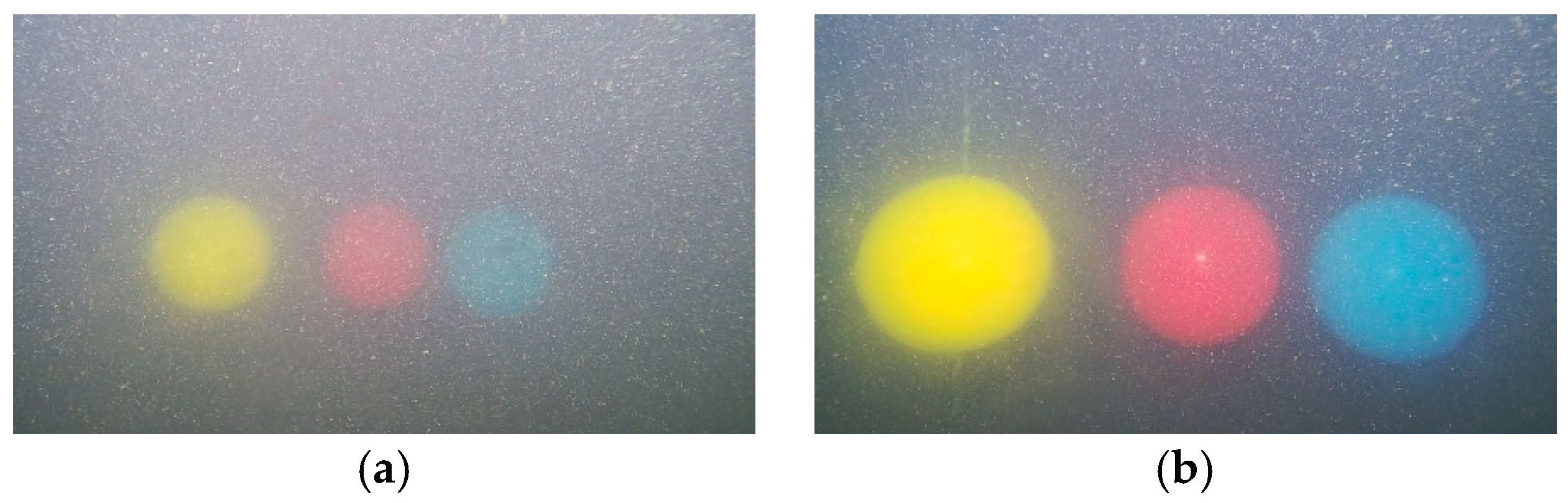
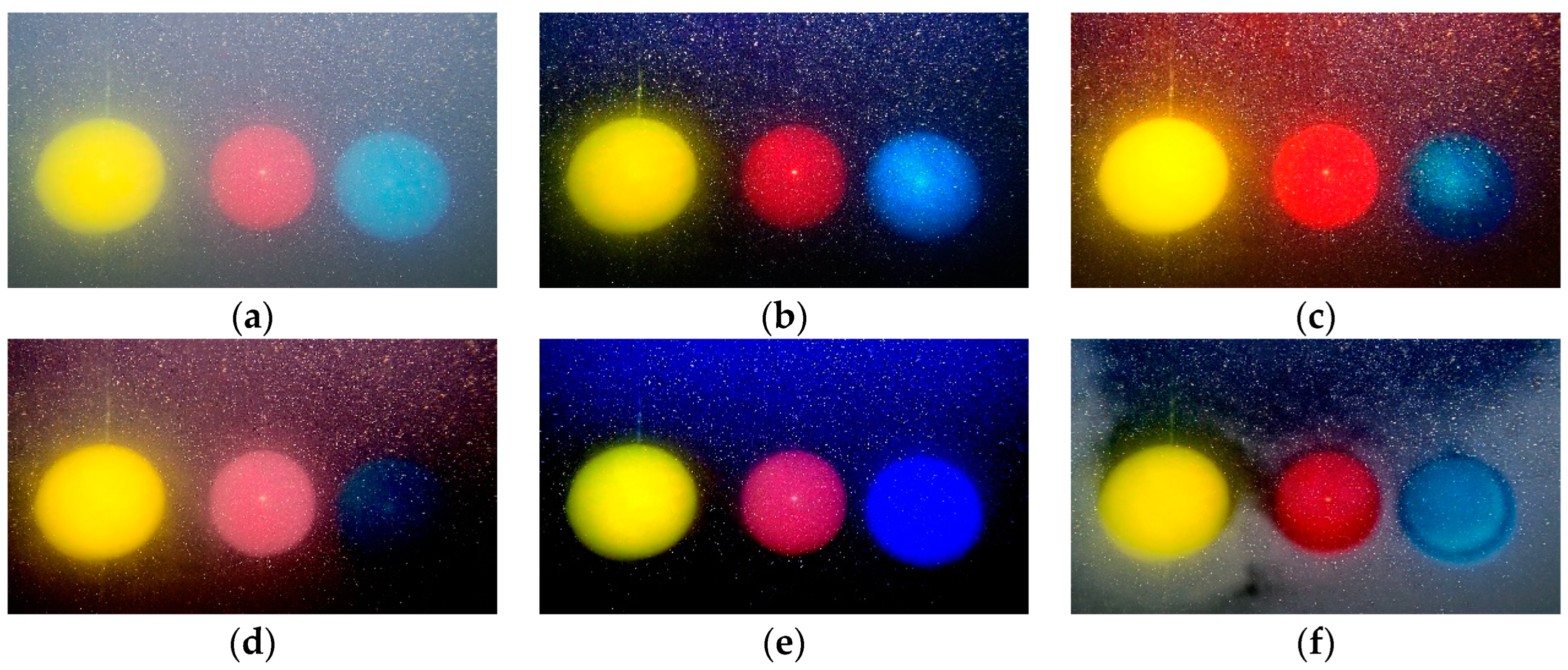
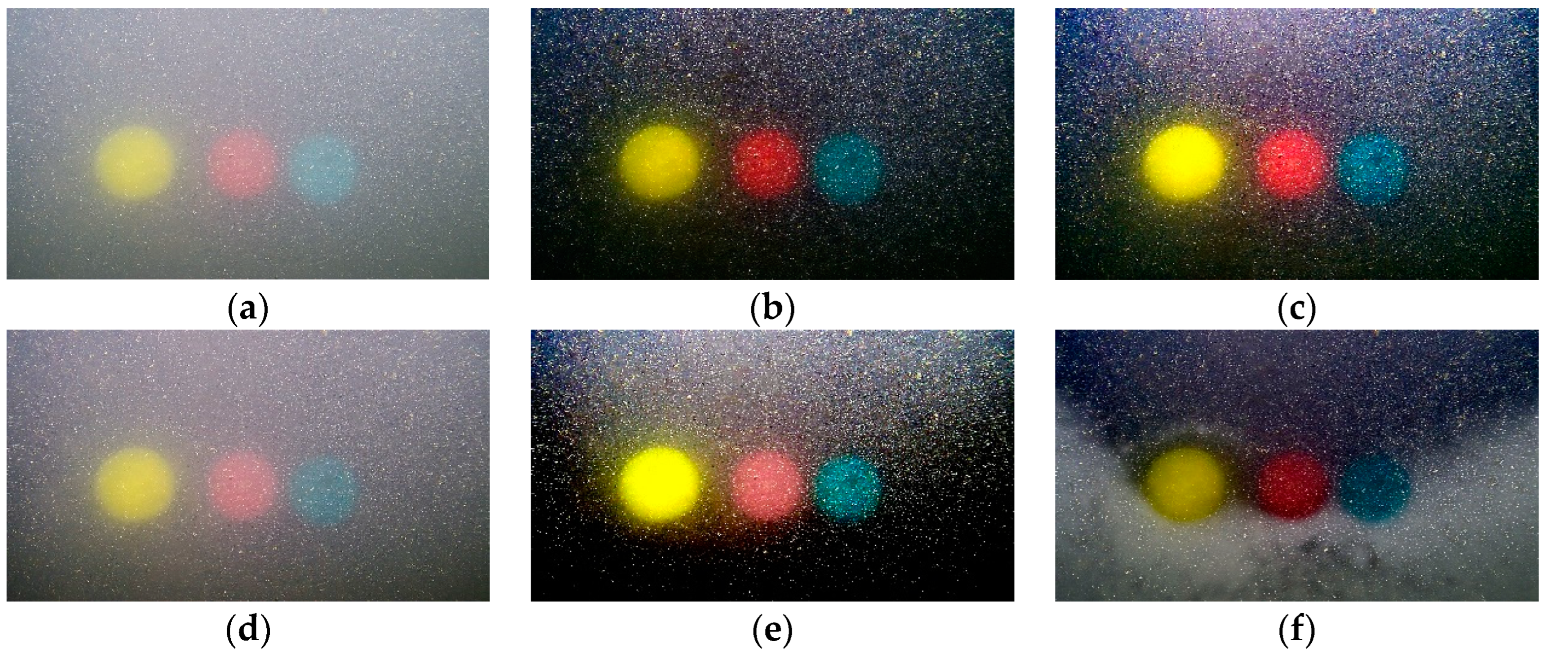
(1)
Experimental verification of multi-balls
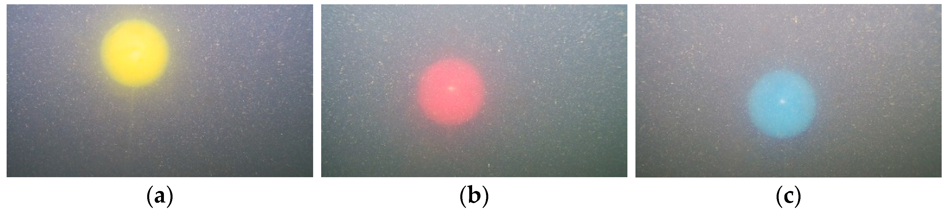
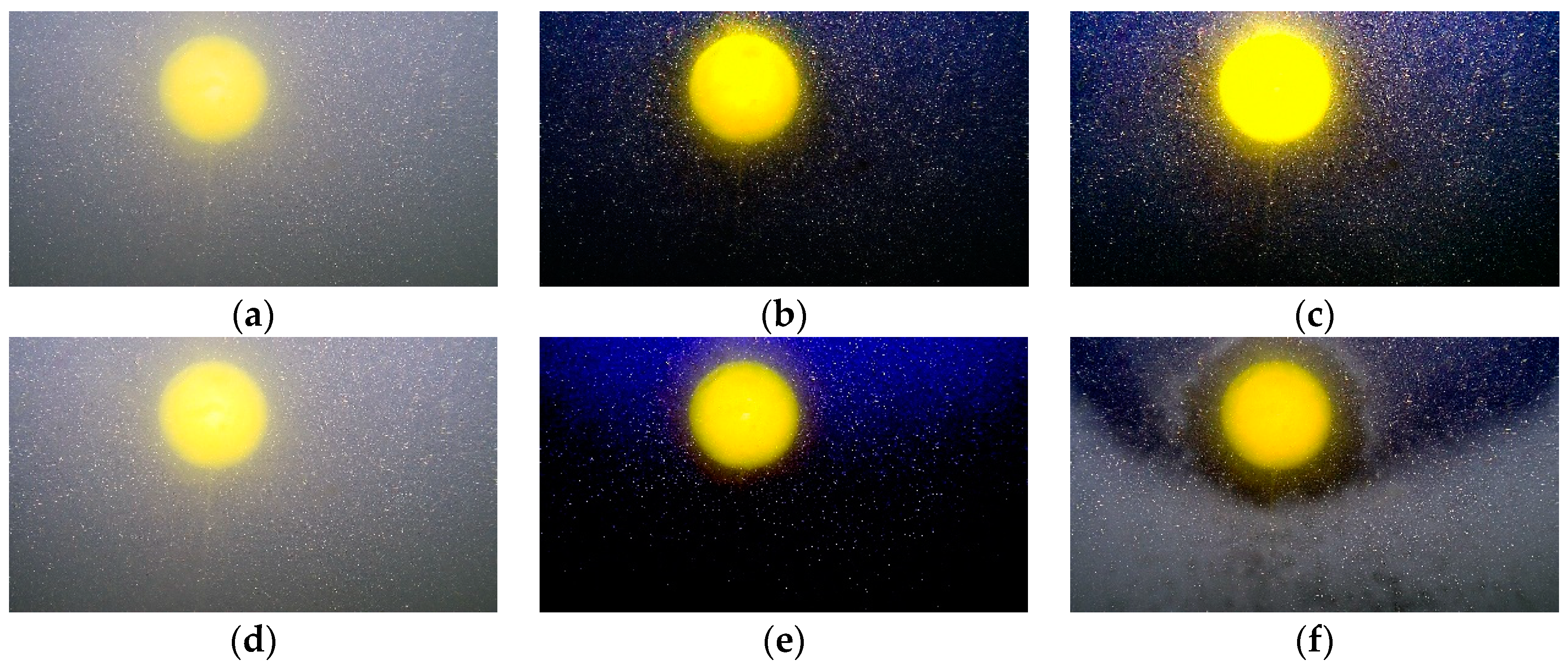
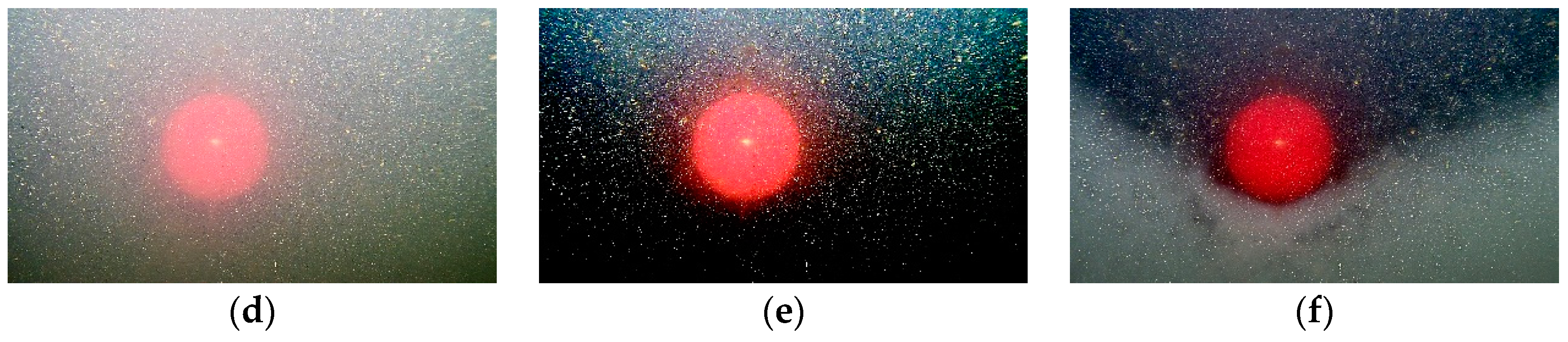
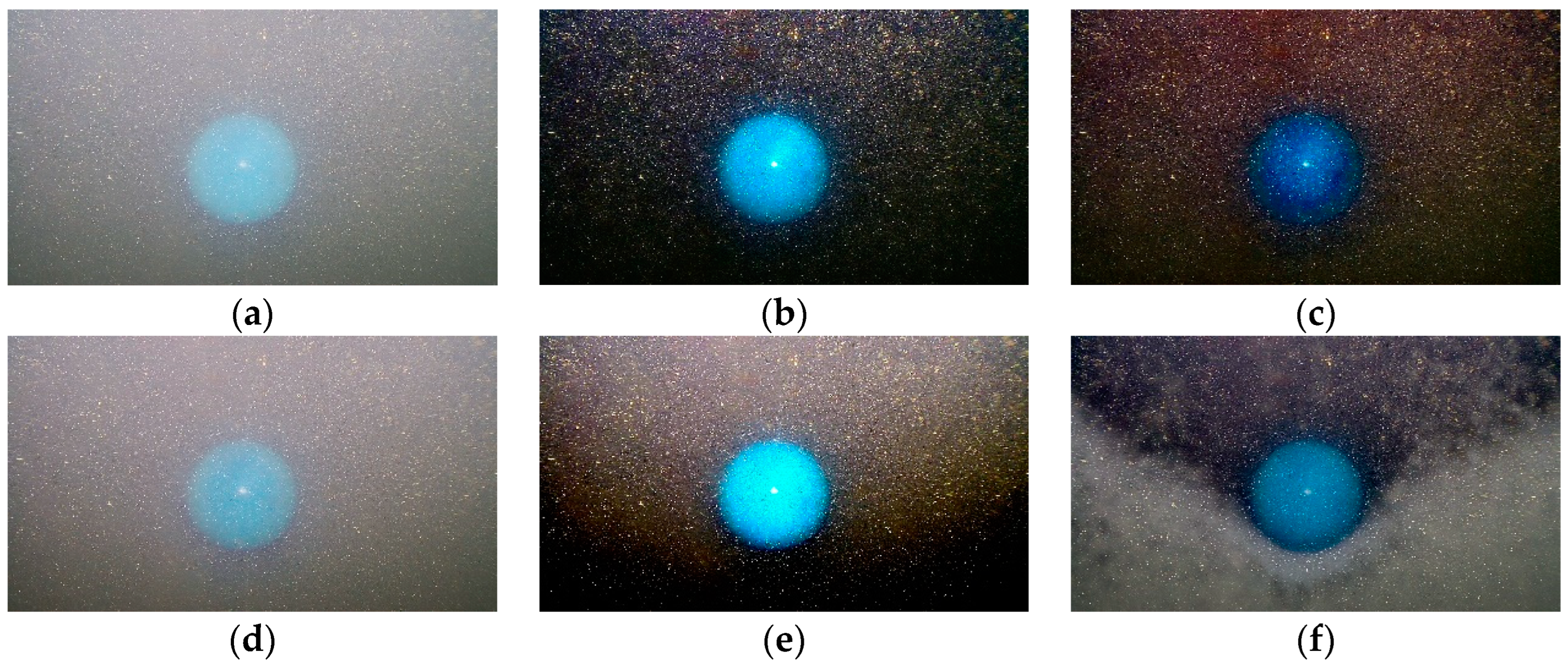
Under the developed method, WCID method [17], IBLA method [18], UDCP method [23], and the MIP method [24], the original images with different distance in Figure 4 are restored, and the results are shown in Figure 5 and Figure 6.
A. Intuitive evaluation
From Figure 5 and Figure 6, it is seen that under the developed method, the clarity of the restored image is significantly improved. Specifically, the target details are more obvious, and the image color is more natural than other methods. The UDCP method has a good de-scattering effect, but the brightness of the image is also enhanced, namely the problem of overexposure. The MIP method has poor restoration effect, and the fog mask in the image is not reduced. Although the IBLA method has a good effect in removing fog mask, the color distortion of the blue ball is serious and the background color of the restored image is changed. Although the WCID method has a good effect on avoiding color distortion, but the background color has changed and the edge details of the target are lost.
B. Objective evaluation
To further demonstrate the effectiveness of the developed method, common image quality evaluation indicators UCIQE (Underwater Color Image Quality Evaluation) [31], UIQM (Underwater Image Quality Measure) [32] and information entropy [33] are selected and objectively evaluated.
The results of these evaluation indicators, mentioned in Figure 5 and Figure 6, are shown in Table 1 and Table 2, respectively.
From Table 1 and Table 2, it is seen that the developed method has the maximum values on these three evaluation indicators, compared with other methods. The results demonstrate the advantages of the developed method to restore underwater images in turbid water and artificial light source.
(2)
Experimental verification of single ball with different color
In AUV detection and salvage, it is always maintained at about 1.0 m away from the target, and the target is always a single color. Three kinds of colors are determined, yellow, red and blue, and the original images are shown in Figure 4. Under the developed method, WCID method [17], IBLA method [18], UDCP method [23], and the MIP method [24], the original images in Figure 6 are restored, and the results are shown in Figure 7, Figure 8 and Figure 9.
A. Intuitive evaluation
From Figure 7, Figure 8 and Figure 9, it is seen that the clarity of the restored image in this method is significantly improved; the target details are more obvious and the image color is more natural than other methods. Other conclusions are similar with the results of multi-ball.
B. Objective evaluation
The results of these evaluation indicators, mentioned in Figure 7, Figure 8 and Figure 9, are shown in Table 3, Table 4 and Table 5, respectively.
From Table 3, Table 4 and Table 5, it is seen that the results of most indicators under the developed method is better than other methods for the underwater image with a single ball, although some indexes of this method are lower than those of other methods. Overall, the results indicate the advantages of the developed method in restoring underwater image in turbid water under artificial light source. Therefore, the developed method could be applied in AUV for detection and salvage.

5. Conclusions

This paper investigates an underwater image restoration method based on multiple frames of sequential images under artificial light source. In the transmission estimation, a new transmission estimation method based on multi frame images is developed to avoid assumptions used in the previous methods, such as “the attenuation factor can be obtained from experience”. Then, an improved background light estimation method is developed for images in turbid water under the artificial light source. The restoration results of different underwater ball images verify the advantages of the developed method in turbid water by comparing the evaluation indexes of UCIQE, UIQM and information entropy with other methods.
The complexity of the algorithms affects their real-time performance. The experiments in this paper are conducted offline. The developed method takes about 2 s to obtain the restoration results. It has to be admitted that there is a certain gap with the real-time requirements of AUV operation (about 1 s). In the future, research on real-time performance of underwater image restoration is required.

Author Contributions

Methodology, T.Z. and Y.G.; Validation, Z.W.; Formal analysis, T.Z. and M.Z.; Data curation, Z.W.; Writing—original draft, Y.G. and Z.W.; Writing—review & editing, T.Z. and M.Z.; Supervision, M.Z.; Project administration, T.Z. Methodology, T.Z. and Y.G.; Validation, Z.W.; Formal analysis, T.Z. and M.Z.; Data curation, Z.W.; Writing—original draft, Y.G. and Z.W.; Writing—review & editing, T.Z. and M.Z.; Supervision, M.Z.; Project administration, T.Z. All authors have read and agreed to the published version of the manuscript.

Funding

This work is supported by the National Natural Science Foundation of China under grant number 52001039, and research fund from the Science and Technology on Underwater Vehicle Technology Laboratory under Grant 2021JCJQ-SYSJJ-LB06903.

Institutional Review Board Statement

Not applicable.

Informed Consent Statement

Not applicable.

Data Availability Statement

Not applicable.

Conflicts of Interest

The authors declare no conflict of interest.

References

  1. Liu, X.; Zhang, M.-J.; Chu, Z.-Z.; Rogers, E. A Sphere Region Tracking Control Scheme for Underwater Vehicles. IEEE Trans. Veh. Technol. 2023. [Google Scholar] [CrossRef]
  2. Kim, L.; Sung, M.; Yu, S.-C. Development of simulator for autonomous underwater vehicles utilizing underwater acoustic and optic al sensing emulators. In Proceedings of the 18th International Conference on Control, Automation and Systems, PyeongChang, Republic of Korea, 17–20 October 2018; pp. 416–419. [Google Scholar]
  3. Xu, S.B.; Zhang, M.H.; Song, W.; Mei, H.B.; He, Q.; Liotta, A. A systematic review and analysis of deep learning-based underwater object detection. Neurocomputing 2023, 527, 204–232. [Google Scholar] [CrossRef]
  4. Zhang, T.C.; Li, Q.; Li, Y.S.; Liu, X. Underwater Optical Image Restoration Method for Natural/Artificial Light. J. Mar. Sci. Eng. 2023, 11, 470. [Google Scholar] [CrossRef]
  5. Lodi Rezzini, D.; Kallasi, F.; Aleotti, J.; Oleari, F.; Caselli, S. Integration of a stereo vision system into an autonomous underwater vehicle for pipe manipulation tasks. Comput. Electr. Eng. 2017, 58, 560–571. [Google Scholar] [CrossRef]
  6. Wang, Y.; Wang, S.; Wei, Q.; Tan, M.; Zhou, C.; Yu, J. Development of an underwater manipulator and its free-floating autonomous operation. IEEE/ASME Trans. Mechatron. 2016, 21, 815–824. [Google Scholar] [CrossRef]
  7. Bobkov, V.A.; Kudryashov, A.P.; Mel’man, S.V.; Shcherbatyuk, A.F. Autonomous Underwater Navigation with 3D Environment Modeling Using Stereo Images. Gyroscopy Navig. 2018, 9, 67–75. [Google Scholar] [CrossRef]
  8. Li, X.; Zhang, M. Underwater color image segmentation method via RGB channel fusion. Opt. Eng. 2017, 56, 023101. [Google Scholar]
  9. Manzanilla, A.; Reyes, S.; Garcia, M.; Mercado, D.; Lozano, R. Autonomous navigation for unmanned underwater vehicles: Real-time experiments using computer vision. IEEE Robot. Autom. Lett. 2019, 4, 1351–1356. [Google Scholar] [CrossRef]
  10. Qin, J.; Li, M.; Li, D.; Zhong, J.; Yang, K. A Survey on Visual Navigation and Positioning for Autonomous UUVs. Remote Sens. 2022, 14, 3794. [Google Scholar] [CrossRef]
  11. Raveendran, S.; Patil, M.D.; Birajdar, G.K. Underwater image enhancement: A comprehensive review, recent trends, challenges and applications. Artif. Intell. Rev. 2021, 54, 5413–5467. [Google Scholar] [CrossRef]
  12. Liu, Y.; Rong, S.; Cao, X.; Li, T.; He, B. Underwater Single Image Dehazing Using the Color Space Dimensionality Reduction Prior. IEEE Access 2020, 8, 91116–91128. [Google Scholar] [CrossRef]
  13. Chen, Z.; Wang, H.; Shen, J.; Li, X.; Xu, L. Region-specialized underwater image restoration in inhomogeneous optical environments. Int. J. Light Electron Opt. 2014, 125, 2090–2098. [Google Scholar] [CrossRef]
  14. Berman, D.; Levy, D.; Avidan, S.; Treibitz, T. Underwater Single Image Color Restoration Using Haze-Lines and a New Quantitative Dataset. IEEE Trans. Pattern Anal. Mach. Intell. 2021, 43, 2822–2837. [Google Scholar] [CrossRef] [Green Version]
  15. Zhao, X.; Tao, J.; Song, Q. deriving inherent optical properties from background color and underwater image enhancement. Ocean. Eng. 2015, 94, 163–172. [Google Scholar] [CrossRef]
  16. Han, P.; Liu, F.; Yang, K.; Ma, J.; Li, J.; Shao, X. Active underwater descattering and image recovery. Appl. Opt. 2017, 56, 6631–6638. [Google Scholar] [CrossRef]
  17. Li, T.Y.; Rong, S.H.; Cao, X.T.; Liu, Y.B.; Chen, L.; He, B. Underwater image enhancement framework and its application on an autonomous underwater vehicle platform. Opt. Eng. 2020, 59, 083102. [Google Scholar] [CrossRef]
  18. Peng, Y.T.; Zhao, X.; Cosman, P.C. Underwater Image Restoration Based on Image Blurriness and Light Absorption. IEEE Trans. Image Process. 2017, 26, 1579–1594. [Google Scholar] [CrossRef]
  19. He, K.M.; Sun, J.; Tang, X.O. Single Image Haze Removal Using Dark Channel Prior. IEEE Trans. Pattern Anal. Mach. Intell. 2011, 33, 2341–2353. [Google Scholar]
  20. Galdran, A.; Pardo, D.; Picón, A.; Alvarez-Gila, A. Automatic Red-Channel underwater image restoration. J. Vis. Commun. Image Represent. 2015, 26, 132–145. [Google Scholar] [CrossRef] [Green Version]
  21. Wang, Y.; Liu, H.; Chau, L.-P. Single underwater image restoration using adaptive attenuation-curve prior. IEEE Trans. Circuits Syst. I Regul. Pap. 2018, 65, 992–1002. [Google Scholar] [CrossRef]
  22. Nair, D.; Sankaran, P. Color image dehazing using surround filter and dark channel prior. J. Vis. Commun. Image Represent. 2018, 50, 9–15. [Google Scholar] [CrossRef]
  23. Paulo Drews, J.R.; Nascimento, E.; Moraes, F.; Botelho1, S.; Campos, M. Transmission Estimation in Underwater Single Images. In Proceedings of the IEEE International Conference on Computer Vision Workshops, Sydney, NSW, Australia, 1–8 December 2013; pp. 825–830. [Google Scholar]
  24. Carlevaris-Bianco, N.; Mohan, A.; Eustice, R.M. Initial results in underwater single image dehazing. In Proceedings of the IEEE Conference on OCEANS, Seattle, WA, USA, 20–23 September 2010; pp. 1–8. [Google Scholar]
  25. Deng, X.Y.; Wang, H.G.; Liu, X. Underwater Image Enhancement Based on Removing Light Source Color and Dehazing. IEEE Access 2019, 7, 114297–114309. [Google Scholar] [CrossRef]
  26. Deng, X.; Wang, H.; Zhang, Y. Deep Sea Enhancement Method Based on the Active Illumination. Acta Photonica Sin. 2020, 49, 0310001. [Google Scholar] [CrossRef]
  27. Hao, J.Y.; Yang, H.B.; Hou, X.; Zhang, Y. Two-Stage Underwater Image Restoration Algorithm Based on Physical Model and Causal Intervention. IEEE Signal Process Lett. 2023, 30, 120–124. [Google Scholar] [CrossRef]
  28. Guo, W.; Zhang, Y.B.; Zhou, Y.; Xu, G.F.; Li, G.W. Rapid Deep-Sea Image Restoration Algorithm Applied to Unmanned Underwater Vehicles. Acta Opt. Sin. 2022, 42, 0410002. [Google Scholar]
  29. Tan, Y.; Qin, J.; Xiang, X.; Ma, W.; Pan, W.; Xiong, N.N. A Robust Watermarking Scheme in YCbCr Color Space Based on Channel Coding. IEEE Access 2019, 7, 25026–25036. [Google Scholar] [CrossRef]
  30. Wang, X.F.; Zhang, X.Y.; Gao, R. Research of Image Edge Detection Based on Mathematical Morphology. Int. J. Signal Process. Image Process. Pattern Recognit. 2013, 6, 227–236. [Google Scholar] [CrossRef]
  31. Yang, M.; Sowmya, A. An underwater color image quality evaluation metric. IEEE Trans. Image Process. 2015, 24, 6062–6071. [Google Scholar] [CrossRef]
  32. Panetta, K.; Gao, C.; Again, S. Human-visual-system-inspired underwater image quality measures. IEEE J. Ocean. Eng. 2016, 41, 541–551. [Google Scholar] [CrossRef]
  33. Avcibas, I.; Sankur, B.; Sayood, K. Statistical evaluation of image quality measures. J. Electron. Imaging 2002, 11, 206. [Google Scholar] [CrossRef] [Green Version]
Figure 1. Flow of transmission estimation where e denotes exponential function.
Jmse 11 01213 g001
Figure 2. Flow of background light estimation.
Jmse 11 01213 g002
Figure 3. Original images of the multi-balls with different distances. (a) 1.5 m distance; (b) 1.0 m distance.
Jmse 11 01213 g003
Figure 4. Original images of the single ball with different colors under the distance with 1.0 m. (a) yellow ball; (b) red ball; (c) blue ball.
Jmse 11 01213 g004
Figure 5. Experimental results of AUV 1.0 m away from the target. (a) original image; (b) developed method; (c) UDCP method; (d) MIP method; (e) IBLA method; (f) WCID method.
Jmse 11 01213 g005
Figure 6. Experimental results of AUV 1.5 m away from the target. (a) original image; (b) developed method; (c) UDCP method; (d) MIP method; (e) IBLA method; (f) WCID method.
Jmse 11 01213 g006
Figure 7. Experimental results of the yellow ball. (a) original image; (b) developed method; (c) UDCP method; (d) MIP method; (e) IBLA method; (f) WCID method.
Jmse 11 01213 g007
Figure 8. Experimental results of the red ball. (a) original image; (b) developed method; (c) UDCP method; (d) MIP method; (e) IBLA method; (f) WCID method.
Jmse 11 01213 g008aJmse 11 01213 g008b
Figure 9. Experimental results of the blue ball. (a) original image; (b) developed method; (c) UDCP method; (d) MIP method; (e) IBLA method; (f) WCID method.
Jmse 11 01213 g009
Table 1. Comparative results of the underwater images with multi-ball and 1.0 m distance.
Original DevelopedUDCPMIPIBLAWCID
UCIQE1.23193.12581.38461.86182.99081.2923
UIQM0.88431.55671.17460.68310.33860.8956
ENTROPY7.01317.45447.42826.92814.67657.1672
Table 2. Comparative results of the underwater images with multi-ball and 1.5 m distance.
OriginalDevelopedUDCPMIPIBLAWCID
UCIQE0.61091.51921.75050.65520.95311.0329
UIQM0.72371.60641.58130.71671.28991.1950
ENTROPY6.83417.08807.17136.91406.31427.1595
Table 3. Comparative results of the underwater image with a yellow ball.
Original DevelopedUDCPMIPIBLAWCID
UCIQE0.99562.41872.10731.06451.81241.1310
UIQM1.00971.88191.03530.94641.66570.8202
ENTROPY7.10956.55874.07517.07663.88177.1193
Table 4. Comparative results of the underwater image with a red ball.
Original DevelopedUDCPMIPIBLAWCID
UCIQE0.57141.69701.80350.58491.16171.0105
UIQM0.69961.68141.67560.71171.27210.8362
ENTROPY5.61387.47336.07405.59676.07177.1237
Table 5. Comparative results of the underwater image with a blue ball.
OriginalDevelopedUDCPMIPIBLAWCID
UCIQE1.85443.12582.38461.86182.99082.5723
UIQM1.03912.25601.97911.10802.86531.3046
ENTROPY6.11327.14006.68556.14096.91776.9818
Disclaimer/Publisher’s Note: The statements, opinions and data contained in all publications are solely those of the individual author(s) and contributor(s) and not of MDPI and/or the editor(s). MDPI and/or the editor(s) disclaim responsibility for any injury to people or property resulting from any ideas, methods, instructions or products referred to in the content.

