Article

Hydrodynamics Analysis of an Underwater Foldable Arm

1
The Institute of Technological Sciences, Wuhan University, Wuhan 430072, China
2
School of Power and Mechanical Engineering, Wuhan University, Wuhan 430072, China
3
R&D Center, Wuhan Second Ship Design and Research Institute, Wuhan 430205, China
*
Authors to whom correspondence should be addressed.
J. Mar. Sci. Eng. 2023, 11(7), 1395; https://doi.org/10.3390/jmse11071395
Submission received: 29 May 2023 / Revised: 2 July 2023 / Accepted: 4 July 2023 / Published: 11 July 2023
(This article belongs to the Section Ocean Engineering)

Abstract

:
Improved designs for underwater manipulators are becoming increasingly important due to their utility in academic and industrial applications. In this work, an experiment was conducted in conjunction with a numerical simulation to investigate the hydrodynamic performance and structural reliability of the proposed foldable arm during the unfolding process at various movement velocities. A large-scale geometric model of the foldable arm with a single degree of freedom (DOF) was constructed. The distribution of the flow field, the movement stability and the equivalent stress of the foldable arm were quantitatively analyzed with a designed tank experiment and the Computational Fluid Dynamics (CFD) simulation. Simulation results show that the maximum deviation of the resistance and torque is 8.04% and 5.73%, respectively, compared with the experimental results of static postures. Comparison results prove the reliability of the numerical model. The results of transient simulation demonstrate that the optimal speed of the foldable arm is 3 Kn and the pressure distribution on the surface of foldable arm is relatively regular. Furthermore, a fluid–structure interaction (FSI) validation study of the foldable arm was presented. For the coupling between the fluid and structural mechanics domains, a nonmatching discretization approach was adopted. The results show that the directional deformation (Z axis) of the foldable arm is less than 0.50 mm. The proposed foldable arm has a large angle of rotation and high stability compared to the existing manipulators.

1. Introduction

Ocean exploration has become an emerging area of research due to many natural resources, which are located beneath the deep sea. Humans cannot withstand the harsh conditions that deep-sea exploration creates, so it presents a unique challenge. Therefore, the research on underwater robots is aimed at reducing human intervention in the deep sea [1]. The manipulators are considered to be the most suitable tool to replace human beings to execute subsea operations [2].
Unmanned underwater vehicles (UUV) are mainly divided into remotely operated vehicles (ROV) and autonomous underwater vehicles (AUV) according to whether human control is necessary during the operation. In some cases, UUVs are outfitted with one or more underwater manipulators. These manipulators consist of a series of rigid bodies (links) that are connected by revolute joints with an appropriate angular displacement between joints and grippers or other interchangeable tools attached to the end effector [2]. Underwater manipulators are used for a variety of underwater missions in different applications such as offshore oil and gas, marine renewable energy (MRE), marine civil engineering, marine science and military applications [3]. Pipeline detection [4], salvage of wrecks [5], hull-cleaning surfaces [6], maneuvering valves, punching, cutting ropes [4], cable laying and maintenance, clearing clutter and fishing nets [2], archaeological work [7], mine disposal [8], capturing UUVs and biological [9] and geological missions are among those that underwater manipulators are designed to carry out.
Special materials are used in the construction of underwater manipulators to allow them to operate in deep waters and deal with the harsh conditions of the subsea environment. Furthermore, underwater manipulators must meet the size of the workspace in which they are to operate, lifting capacity, wrist torque and other relevant requirements, depending on the missions for which they are designed [2]. As computational equipment improves, the manipulator design is increasingly becoming a simulation-based method, with Computational Fluid Dynamic (CFD) simulations replacing the reliance on traditional large-scale experiments on complex testbeds. Complex design iterations can be tested quickly and inexpensively using this computer-driven simulation that might be expensive and time-consuming to replicate and test in real life. This also allows for more precise data aggregation and statistical analysis that would otherwise be impossible in traditional experiments [10].
By comparing mathematical simulation results with ADAMS simulation results, Li et al. [11] investigated a spatial parallel manipulator’s dynamic and inverse kinematics with three degrees of freedom (DOF). The Newton–Euler method was used to establish the dynamic equations. Some joint constraint forces were eliminated, and actuator forces were derived based on the different kinematic constraints of the legs and the movable platform. Kuriyama et al. [12] devised a control system to prevent the six DOF manipulators from sloshing. The optimum controller was designed with the Hybrid Shape Approach to satisfy various control specifications such as sloshing suppression, transfer time, constraints of the 6 DOF manipulator, etc., considering the time and frequency characteristics. The CFD simulations and experiments showed that the designed control systems met the current requirements well. The CFD simulations and experimental results demonstrated that the designed control systems satisfied the present requirements well. Huang et al. [13] used ADAMS software to perform dynamics analysis on a single DOF parallel manipulator. They performed force analyses on each manipulator link using the method of body-separation according to the dynamics sequence solution. They drew the force–time curves of all the hinge points in ADAMS. By attaching two manipulators to an ROV, Hachicha et al. [6] presented a novel design of an underwater ship hull-cleaning robot (ARMROV). Using the dynamic equivalence approach, the dynamic stability of the hull was investigated and verified during the cleaning process. They ran a system simulation on the SimMechanics platform to assess the efficacy of the dynamic equivalence approach in system stability, and the simulation results demonstrated the efficacy of the stability approach and the feasibility of the proposed solution. Few studies have been conducted on the stability of manipulators during operation. Kazakidi et.al. [14] focused on an arm geometry performing prescribed motions that reflect octopus locomotion within the immersed-boundary framework. This method was compared with a finite-volume numerical approach to determine the mesh requirements that must be employed for sufficiently capturing not only the near wall viscous flow but also the off-body vortical flow field in intense forced motions. The objective was to demonstrate and exploit the generality of the immersed boundary approach to complex numerical simulations of deforming geometries. Results show that the incorporation of arm deformation increased the output thrust of a single-arm system and sculling motion combined with arm undulations providing an effective propulsive scheme for an octopus-like arm. Kolodziejczyk [15] obtained the transient hydrodynamic load of a single DOF underwater manipulator by using CFD simulations with dynamic mesh employed to generate the motion of arm. He presented the method of determination of transient hydrodynamic coefficients for the robotic arm, based on the time-dependent hydrodynamic load, and the results showed that hydrodynamic coefficients for a single DOF underwater robotic arm depend on the shape of the manipulator and were variable in time. Furthermore, the hydrodynamic properties of each component of the underwater manipulator remain to be investigated. Afra et al. [16,17] propose a hybrid model that includes an explicit Lattice Spring Model and Immersed Boundary non-Newtonian Lattice Boltzmann Method to simulate the effect of fluid flow on the structure.
In this work, a novel foldable arm is proposed to improve the motion stability and reduce control costs of the underwater manipulator. The experiment is conducted in conjunction with a numerical simulation to investigate the hydrodynamic properties of the proposed foldable arm with varying movement velocities during the unfolding process. The distribution of the flow field and the resistance and torque of the foldable arm in various postures are quantitatively analyzed. Fluid structure interaction (FSI) simulation is carried out to investigate the structure performance of the foldable arm.
The layout of the remainder paper is as follows: the proposed model and structural parameters are presented in Section 2. The experimental test setup is given in Section 3. In Section 4, validation of the numerical method and FSI simulation are detailed. Finally, the major conclusions of this study are gathered in Section 5.

2. Design of Foldable Arm

Exploring the ocean and interpreting the underwater behavior is significant in today’s world. Convenient accessories are required to minimize the presence of a human operator underneath the ocean to examine the ocean bed, clean the hull and even recover the AUV [1]. The manipulator is widely used in the exploration of underwater resources, captures underwater vehicles and has a broad application prospect. The manipulator’s stability and safety, on the other hand, are key technologies that limit its development, and the accurate resistance prediction is closely related to its stability and safety. To improve the motion stability of the underwater manipulator, this work proposed a novel and large-scale foldable arm with a single degree of freedom (DOF).
Figure 1 depicts the full-scale foldable arm. Four link rods, three plates and eight revolute bolts make up the structure. The bottom plate secures the foldable arm to an underwater vehicle, allowing it to rotate flexibly around bolts driven by a single hydraulic device while a synchronous device is installed in the middle. To maintain the light weight, durability and affordability of the foldable arm, the components are manufactured with an aluminum alloy [1]. Three typical postures of the foldable arm during the unfolding process are shown as Figure 1a–c. α is the included angle between the two link rods, and the angle of stage 1, stage 2 and stage 3 is 0°, 90° and 180°, respectively.
Figure 2 depicts the geometric dimension and the unfolding process of the foldable arm. The foldable arm unfolds dynamically along the positive X-axis and moves in a straight line along the positive Z-axis. The rotation angle α ranges from 0° to 180° as the posture progresses from Stage 1 to Stage 3, allowing a full range of motion for the arm. For the entire unfolding process, the motion time is approximately 21.6 s.

3. Tank Experiment

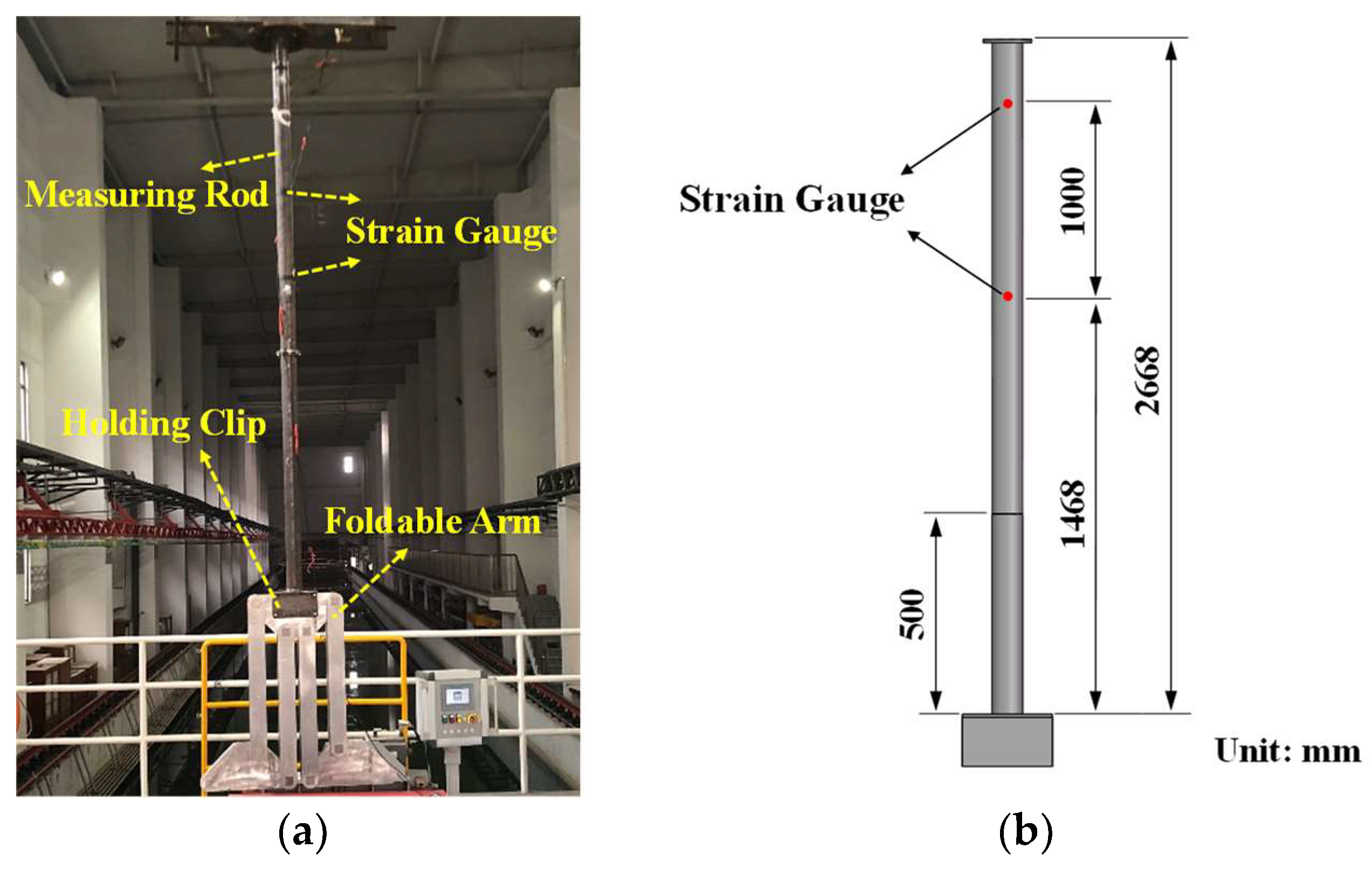
3.1. Experimental Setup

To test the hydrodynamics performance of the underwater foldable arm, the experiments were carried out in a towing tank with the towing vehicle. The towing tank measures 135 m × 7 m × 3 m. The link rods and plates of the foldable arm are riveted together with square bolts and cross square holes to realize the mutual conversion of three different postures. The foldable arm is fastened to the designed measuring rod with the holding clip, and the foldable arm is symmetrically distributed on both sides of the axis with the measuring rod serving as the axis of symmetry. Two strain gauges are fastened to the measuring rod, and the DH5922N dynamic strain collector (Donghua Testing Technology Co., Ltd., Jiangsu, China) is used to collect electrical signals. The size is 2340 mm × 220 mm × 100 mm when the foldable arm is fully extended (Figure 1c). Before the experiment, the measuring rod is secured to the towing vehicle and calibrated. The foldable arm is completely submerged in water, and the measuring rod is submerged underwater to a depth of 500 mm in the experiment. The hydrodynamics characteristics including the flow field, the resistance and torque of three different postures are measured by these mechanical measuring devices. The towing vehicle accelerates slowly with the control of the governor, and when the velocity reaches 1.286 m/s (2.5 Kn), the towing vehicle remains in uniform motion for a moment. The towing vehicle then gradually accelerates to 1.543 m/s (3.0 Kn) and then continues to move at a uniform motion for a moment again. The towing vehicle eventually comes to a halt. The foldable arm and the schematic of the recirculating water tank along with the detailed arrangement of the mechanical measuring devices are shown in Figure 3.

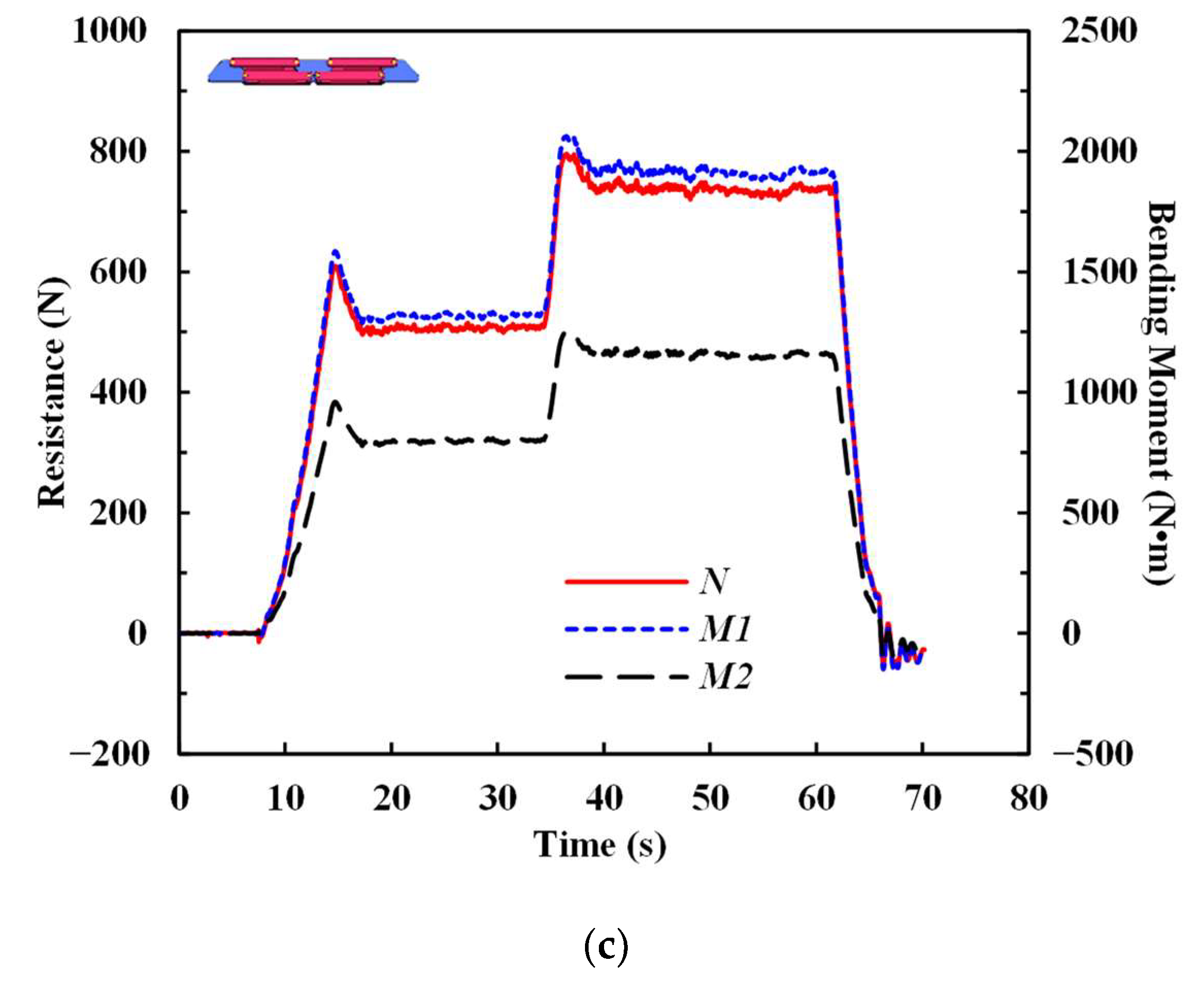
3.2. Experimental Results

The bending moment at two points (M1 and M2) can be obtained by using strain gauges. Considering that there are no external forces on the measuring rod in the horizontal direction, the horizontal shear force is the horizontal resultant force of the foldable arm in the towing tank during the whole process, which is the resistance that needs to be measured in the experiment. The torque of the foldable arm at three different postures (as shown in Figure 1) can be obtained through correlation calculations, and the equations are as follows.
M = W E ε
N T = M 1 M 2 Δ L
L 1 = L 2 M F r
N T = F r
where W is the cross section modulus, E is the Young’s modulus, ε represents the strain, NT is the shear force, M1 (M2) is the bending moment that obtained by the strain gauges, Δ L represents the distance of two strain gauges, M is the torque, Fr is the resistance, L 1 is the distance from the center of gravity of mechanical measuring devices to the bottom of foldable arm and L 2 is the distance from the measuring point to the bottom of foldable arm (the side away from the liquid surface).
Figure 4 shows the dynamic evolution of the resistance and bending moment of the foldable arm with the different movement speeds. The total resistance of the foldable arm in the process of underwater movement is obtained by subtracting the resistance of the measuring rod, as shown in Table 1. At the same velocity, the resistance changes slightly, and the torque decreases significantly (up to 74%) as the postures of foldable arm changes from Stage 1 to Stage 3. The reason is that the center of gravity of the foldable arm changes, but the incident flow surface remains the same with the change of postures.

4. Numerical Simulation

The hydrodynamic performances were also simulated by the commercial package FLUENT Version 2020R2 (ANSYS Inc., Canonsburg, PA, USA) to solve the system of Reynolds Averaged Navier–Stokes (RANS) equations using a finite-volume method (FVM), which included the overset mesh technique.
Several turbulence models, including the Reynolds stress model (RSM), Renormalization group (RNG) k ε and Shear stress transport model (SST) k ω , have been proposed for underwater-device simulation. Huang et al. [18] evaluated the applicability of turbulence models when predicting the hydrodynamic characteristics of propellers. The experimental results showed that the RSM had a higher prediction accuracy than the standard model and the RNG model. Cheng [19] demonstrated that the RNG k ε model can accurately predict the pressure and force coefficients of three-dimensional flat ovoid as it approached a wall at low velocity. Song [20] simulated a hybrid-driven underwater vehicle using the SST k ω model. To simulate the oil tank, Zhang and Wang [21] adopted the SST k ω model. Yu et al. [22] investigated the drag of a mini AUV using the standard k ε , RNG k ε and SST k ω turbulence model. In the present work, after a comparison of different turbulence models in the existing research, the SST k ω model was chosen to simulate the underwater foldable arm. The SST k ω model combines the advantages of the k ω model and the   k ε model, which makes it have a wider application [23]. It has the following advantages:
(1)
This model can adapt to various physical phenomena where pressure gradient changes.
(2)
It applies to the viscous layer, and it can precisely simulate the phenomenon of the boundary layer through the application of the near-wall function without using the viscous damping function which may distort easily.
The solution method is a pressure–velocity coupling scheme with the coupled algorithm. Spatial discretization is performed using a least-squares cell-based gradient with second order pressure, momentum, turbulent kinetic energy and specific dissipation rate in second-order upwind. The hybrid initialization method is employed. The Reynolds-Averaged Navier–Stokes (RANS) method is adopted for solving the governing equations. The flow is incompressible, and the governing equations are as follows:
For incompressible flow, the differential form of the continuity equation is
u i x i = 0
Momentum equation
ρ ( u i t + u i u j x j ) = x j ( μ u i x j ) p x j
where u i is the velocity component, x i is the coordinate component, ρ is the flow density, p denotes the pressure, t is the time and μ is the dynamic viscosity.

4.1. Validation of the Numerical Method

The environment parameters (fluid pressure, velocity and viscosity) of static simulations are consistent with the environment of tank experiment. The computational domain is set as a rectangular space, which is depicted in Figure 5. The size is 200 L × 20 W × 10 H, where L is the length and W and H are the width and height of the foldable arm. Due to the complicated geometry of the foldable arm, the computational domain is divided into many sub-domains, and the mesh types are set appropriately to improve the mesh quality [24]. The overset mesh consists of the background mesh and component mesh. The GAMBIT 2.4.6 (ANSYS Inc., Canonsburg, PA, USA) meshing software is used to generate background meshes with hexahedral elements. The polyhedral meshes for components are generated using the FLUENT Meshing (ANSYS Workbench, 2020R2) software. Because all parts share the same coordinate system, the background meshes and component meshes are assembled. The foldable arm moves in a straight line along the positive Z-axis with the constant speed of 3 Kn. Table 2 shows the boundary values that are configured before the solver’s initialization. The momentum Equation (6) in the steady-state simulation does not consider the time term.
According to the specified conditions and methodologies, the resistance and bending moment of the foldable arm at three different static postures are obtained. Figure 6 shows the pressure distribution on the foldable arm at three different postures (Stage 1, Stage 2 and Stage 3) when the velocity of towing vehicle is 3.0 Kn. The maximum pressure occurs on the incident flow surface of the foldable arm, and the maximum pressure is approximately the same at three different postures. The reason is that the foldable arm’s incident flow surface does not change with the change of postures. As shown in Table 3, the resistances and torques of three different postures are obtained. The torque of the foldable arm decreases gradually with the change of posture from Stage 1 to Stage 3, and Stage 3 has the smallest torque because the center of gravity in this posture is closest to the liquid surface.
The simulation results of the foldable arm at three static postures are compared with the experimental results (the towing velocity is 3.0 Kn), and the comparison results are shown in Figure 7. The maximum deviation of the resistances and torques are 8.04% and 5.73%, respectively, that can meet the design requirements, demonstrating that the finite element model of the foldable arm used in this work is effective for accurately predicting the resistance and torque of the underwater foldable arm.

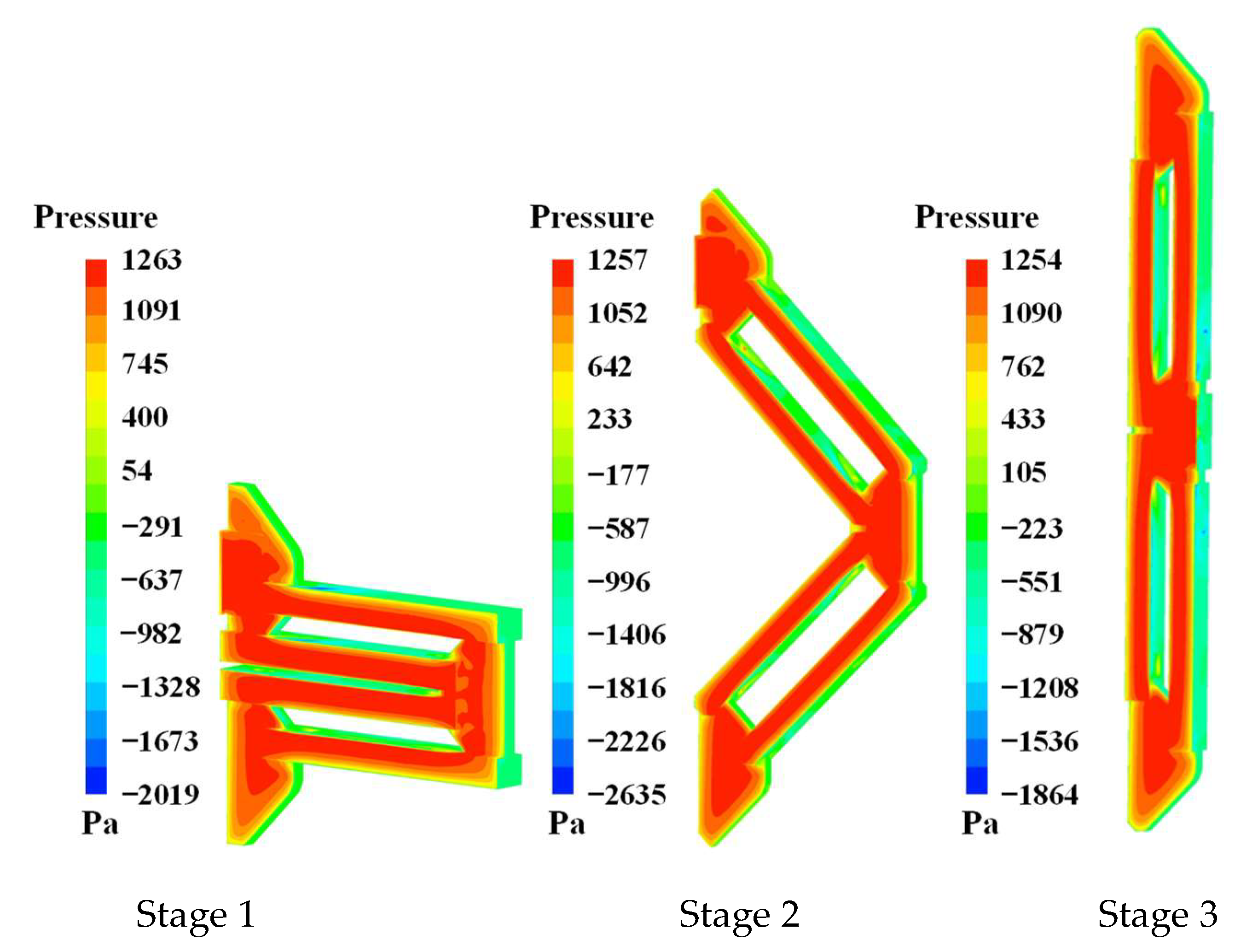
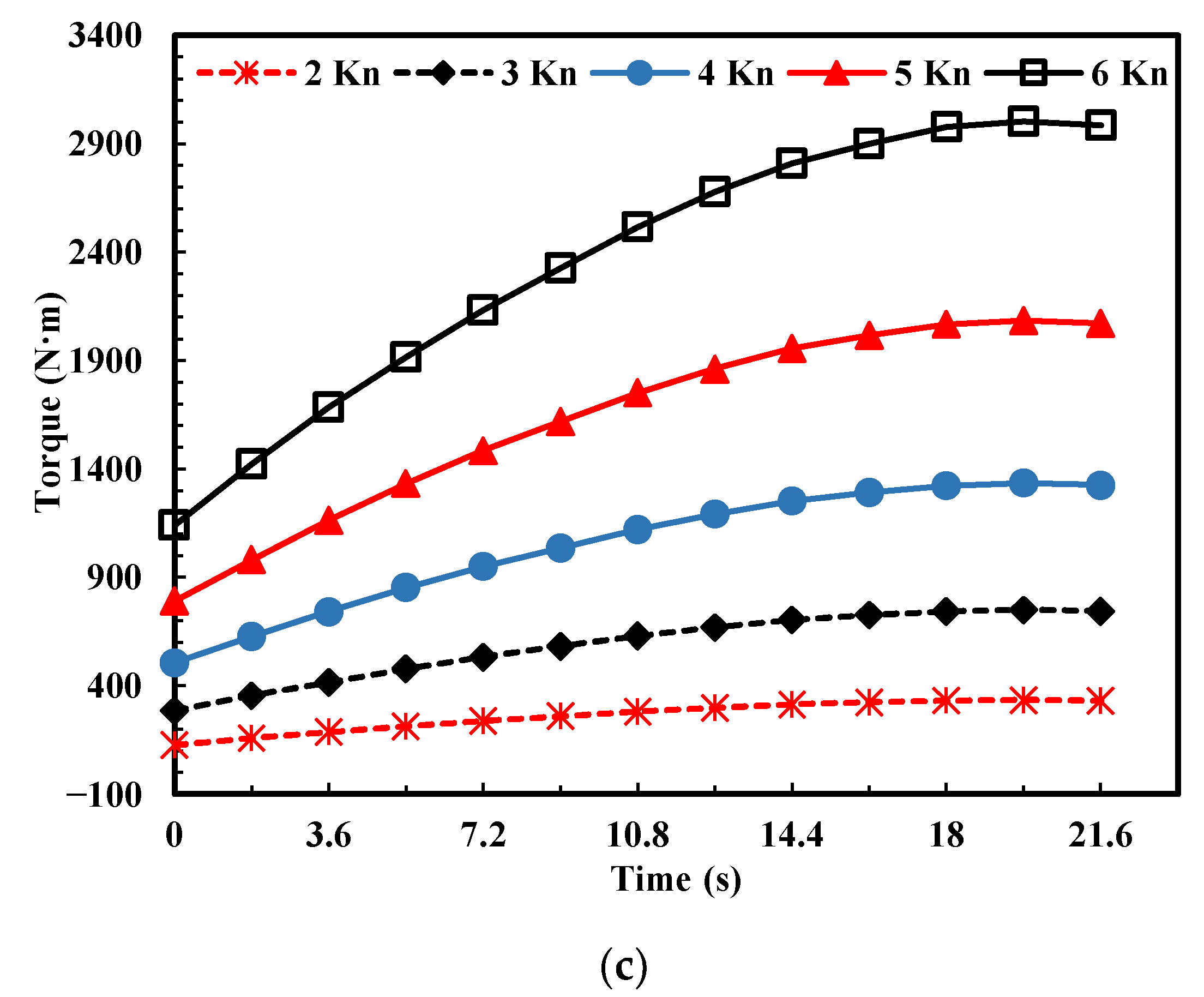
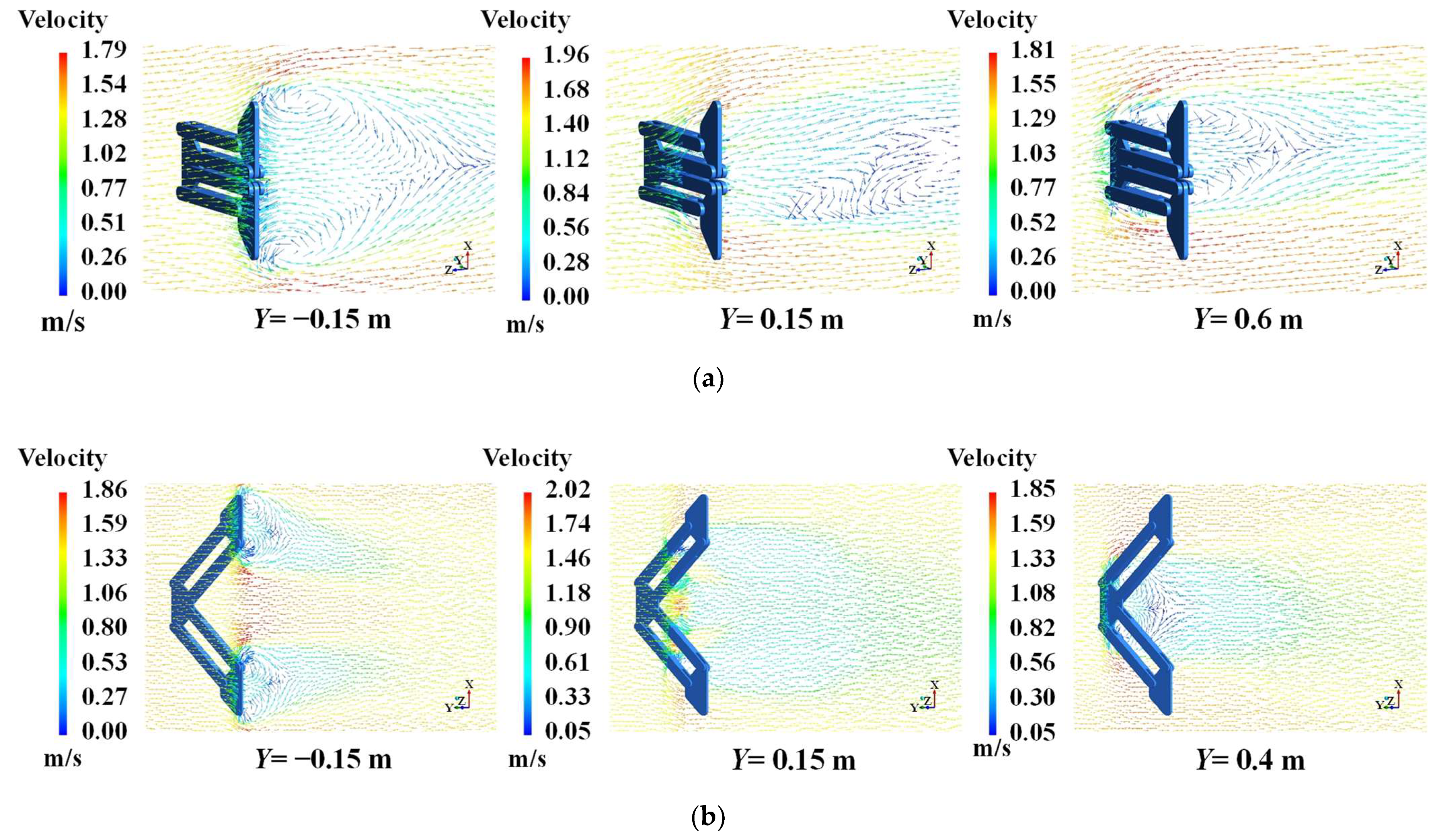
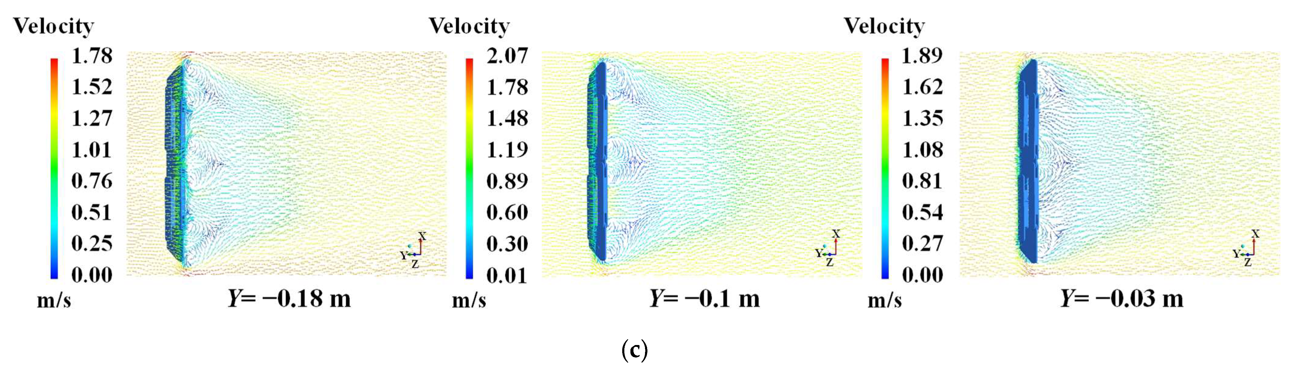
4.2. Hydrodynamics Performance of the Unfolding Process

The simulation results of static postures prove the reliability of the numerical model of the foldable arm. In order to further investigate the mechanical properties of the foldable arm, the transient simulation during the unfolding process was carried out. The foldable arm moves in a straight line along the positive direction of the Z-axis and unfolds dynamically along the positive direction of the X-axis. The angular velocity of the foldable arm is 0.073 rad/s, so that the motion time is 21.6 s. The speed of uniform linear motion is 2 Kn, 3 Kn, 4 Kn, 5 Kn and 6 Kn, respectively. The user-defined function (UDF) using the grid motion method for the moving link imposes the dynamic unfolding of the foldable arm. For the foldable arm, a free quadrilateral mesh with boundary layers is generated to obtain more details of fluid flow and fluid pressure around the key components, as shown in Figure 5. The boundary values of dynamic simulations are as shown in Table 2.
Figure 8 shows the change of resistance and torque of the foldable arm at different velocities (uniform linear motion) during the dynamic unfolding process. Figure 8a–c represent the total resistance of the foldable arm, the torque that the foldable arm rotates around the X-axis and Y-axis, respectively. As shown in Figure 8a, the resistance change is not obvious with the change of posture (from 0 s to 21.6 s), and the overall resistance is relatively stable during the dynamic unfolding process. As the kinematic velocity increases, the resistance of foldable arm increases significantly. At the same time, the magnitude of change in resistance increases sharply. As shown in Figure 8b, the torque that the foldable arm rotates around the X-axis decreases with the change of posture (from 0 s to 21.6 s), and the reason is that the center of gravity gradually approaches the X-axis, but the resistance of the foldable arm is almost unchanged during the dynamic unfolding process. As the kinematic velocity increases from 2 Kn to 6 Kn, the torque that the foldable arm rotates around the X-axis increases significantly, and the magnitude of change in torque increases obviously with the posture change of the foldable arm. The torque that the foldable arm rotates around the Y-axis increases with the change of posture (from 0 s to 21.6 s), and the reason is that the center of gravity gradually moves away from the Y-axis, but the resistance of the foldable arm is almost unchanged during the dynamic unfolding process. As the kinematic velocity increases from 2 Kn to 6 Kn, the torque that the foldable arm rotates around the Y-axis increases significantly, and the rate of change of torque increases obviously with the posture change of the foldable arm, as shown in Figure 8c. As shown in Figure 8, considering the overall resistance of the foldable arm and the torques rotate around the X and Y axes, the optimal motion velocity of the foldable arm is 3 Kn.
After determining the optimal motion velocity of the foldable arm, further investigation of the hydrodynamic performance when the foldable arm moved at the speed of 3 Kn was carried out. Pressure distributions on the foldable arm during the unfolding process are shown in Figure 9. Because the foldable arm is perpendicular to the direction of the incoming flow, the maximum pressure occurs on the incident flow surface of the foldable arm, and the pressure generated by the fluid all acts on the face of the flow of the foldable arm. The pressure on the inner side of the link rods is the lowest. The reason is that the velocity gradient appears on the non-flow surface of the link rod, and the fluid flow velocity increases, and the pressure decreases. Moreover, the maximum deviation of the highest pressure and lowest pressure are 4.13% and 14.09%, respectively. Meanwhile, the areas of high pressure and low pressure appear in the same position under different postures, and the results show that the pressure distribution on the surface of the foldable arm is relatively regular, allowing the foldable arm to maintain a higher level of stability throughout the movement.
To better display and analyze the flow field of the foldable arm during the unfolding process, many planes were established along the movement direction of the foldable arm (located in the X–Z plane) to project the flow-field distribution. Figure 10 shows the flow characteristics of the foldable arm at various times (t = 0 s, 10.8 s and 21.6 s, respectively). Because the influence of the sea bottom is ignored, the velocity distribution on different sections of the foldable arm is symmetrical. Meanwhile, the maximum velocity is 1.96 m/s, 2.02 m/s and 2.07 m/s, respectively. As shown in Figure 10a, the maximum velocity occurs on the upper and lower ends of the foldable arm. The velocity increases dramatically once the flow is no longer blocked. When the foldable arm unfolds to these postures shown in Figure 10b, the maximum velocity appears not only at the upper and lower ends of the foldable arm but also at the middle position of the mechanism. Meanwhile, the phenomenon of backflow does not exist in the plane of Y = 0.15 m. As a result of the structural changes, the fluidity in the middle of the foldable arm improves. The maximum velocity occurs at the upper and lower ends of the foldable arm in Figure 10c. However, due to a large number of components in the middle of the foldable arm, the smooth flow of fluid is impeded. Therefore, a large low-speed region appears. According to the continuous equation, once the velocity decreases, the pressure must increase, so that the components in this region will bear high dynamic pressure. The results show that the fluidity of water around the foldable arm changes with the change of posture during the unfolding process. The foldable arm, as opposed to the manipulator consisting of multiple flexible links and joints proposed by Subudhi and Morris [25], does not produce large-amplitude vibrations and thus maintains better stability.
The hidden mechanism of the influence of postures change of folding arm on the backflow is discussed from the perspective of the change of intermolecular adhesion of the flow. As the fluid flows around the foldable arm, the viscosity acts as a force between the fluid and the surface. The drag is caused by these intermolecular forces. However, due to intermolecular forces, the surface of the foldable arm also attempts to attach the fluid to itself. This also leads to the fluid adhering to the surface (no-slip condition). The layer above this adherent fluid layer will not be able to simply split itself away from the adhesive layer, because the intermolecular attraction and pressure forces also work between the layers. As a result, any fluid flow around an object tends to flow along with the profile of the surface. Under some circumstances, the fluid is no longer able to flow along with the surface profile as the structure of the object changes drastically or the fluid flows around the blunt body. The flow or boundary layer begins to separate from the surface of object. Vortices frequently form downstream of the separation point, creating a turbulent flow [26].

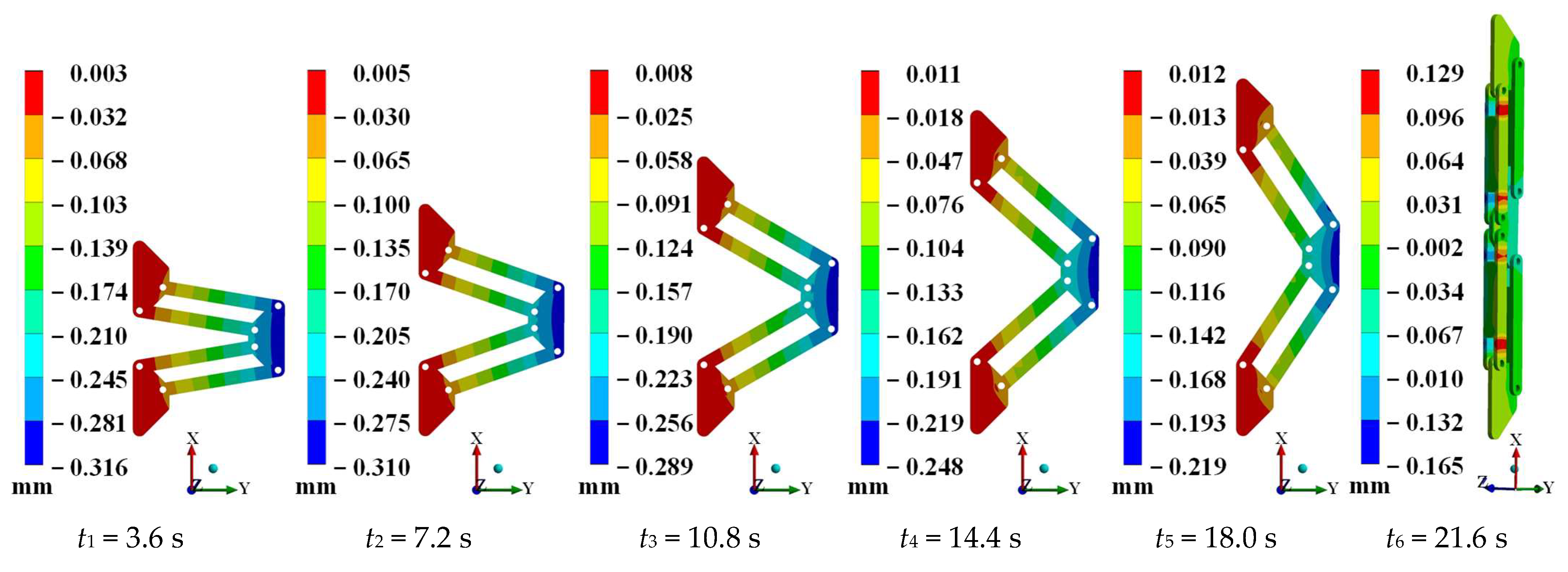
4.3. Fluid Structure Interaction of the Dynamic Unfolding Process

The entire computational fluid region is divided into two domains. One is a stationary rectangular domain, and the other is a mobile domain that surrounds the foldable arm. Two separate grids are generated using Meshing software in Workbench for stationary and mobile fluid domains. Tetrahedral cells are used in all fluid and solid domains in this analysis due to the complexity of foldable arm geometry. A smaller cell size is used at the foldable arm. The overall fluid domain dimensions and the grids on the foldable arm are shown in Figure 5. The Spalart–Allmaras turbulence model, a one-equation model that solved a modeled transport equation for the kinematic eddy turbulent viscosity, is used. The high-strength aluminum alloy is used for the foldable arm due to its low density, high strength, good processing performance and excellent welding performance. And the material properties of the foldable arm are shown in Table 4.
A fluid–solid interface boundary condition is applied on all faces of the foldable arm exposed to fluid. The ANSYS workbench is used to couple the finite element analysis (FEA) and CFD analyses through the system coupling component. FSI is the study of the mutual effects between deformable structures and a surrounding fluid. The total simulated time is 22 s for two-way coupled simulations. The time step is 0.05 s used in the fluid flow simulation, transient structural analysis and in the coupled analysis. Two data transfers are performed to transfer the force data from CFD to FEA solver and the displacement data from FEA to CFD solver, as shown in Figure 11. The contributing region for the data transfer is a fluid–solid interface. This two-way data transfer is accomplished by enabling the ‘smoothing’ and ‘remeshing’ in dynamic mesh settings of the FLUENT software. To improve the element quality by moving locations of nodes with respect to surrounding nodes, the smoothing method is used, and the diffusion parameter is selected as 1.5. Remeshing is used to relocate and adjust the grid with minimum and maximum length scales. The maximum cell skewness is 0.9 to ascertain the quality of the grid. Using the proper dynamic mesh methods and settings in two-way fluid–structure interaction analysis is important to resolve the convergence issues commonly raised during iterative solution. The boundary conditions of the FSI simulations are shown in Figure 5. A fixed support is applied to the lower edge surface of the bottom plate. The internal wall of the solid body is defined as the fluid–structure interface. An additional fluid–structure interface is introduced at the external walls of the solid body to simulate the foldable arm submerged under water. At the boundary between the fluid and solid domains, the following equation applies [27].
p n + τ · n = σ · n
where τ is the fluid effective shear stress tensor, σ is the Cauchy stress tensor and n is the normal vector.
The coupled FSI model provides a detailed insight into the structural response of foldable arm components against the imposed fluid loads by providing all the results that are possible from a standalone FEA analysis. From Figure 12, it can be observed that the maximum directional deformation (Z-axis) in the evaluated cases is relatively small (less than 0.50 mm) and the maximum deformation is along the direction of fluid loading (a negative sign in a vector only indicates direction). The maximum directional deformation occurs on the middle plate during the unfolding process, and the area of maximum directional deformation on the middle plate gradually decreases with the dynamic unfolding of the foldable arm. When the foldable arm is fully unfolded (t = 21.6 s), the maximum directional deformation (Z-axis) occurs on the link rods, near the hinge point of the links and plates. The maximum deformation area is symmetrically distributed along the plate (t = 21.6 s), but the deformation direction is opposite. Vortex distributions are different around the plates (Figure 10c). Due to the unequal distribution of material on the plates, the maximum deformation occurs only on the one side of the link rods.
Figure 13 shows the transient stress of the foldable arm during the unfolding process. The equivalent stress gradually increases with the dynamic unfolding of the foldable arm. The maximum equivalent stress of the foldable arm is 578.99 MPa when the foldable arm is fully unfolded, and the maximum equivalent stress occurs at the outer edge of the plate where it is hinged to the link. It is clearly evident that this area would require additional reinforcement. Except for the above positions, the von-Mises stress of the other position is less than the tensile ultimate strength (3.1 × 10⁸) of the material.
Compared with the water hydraulics manipulator designed by Hassan [28], the foldable arm proposed in this work has a larger rotation angle, which effectively increases the working space of the manipulator. Furthermore, each link of the foldable arm is an integrated structure, which can ensure link synchronization of the links and reduce the control difficulty.

5. Conclusions

This work presented experimental and numerical studies to investigate the hydro-dynamic and mechanical properties of the proposed foldable arm during the dynamic unfolding process with various movement velocities. A large-scale geometric model of a foldable arm with single DOF was constructed. A designed tank experiment and a CFD simulation were used to quantify the flow field distribution, resistance and torque and structural performance of the foldable arm. The comparison results of the tank experiment and the static simulation verified the reliability of the simulation model. The transient simulations show that the optimal motion velocity of the foldable arm is 3 Kn; meanwhile, the flow field around the foldable arm is relatively stable such that the foldable arm can maintain a higher level of stability. The following are the primary conclusions of this work:
(1)
The maximum deviation of the resistances and torques between the static posture simulation and experiment results (the towing velocity is 3.0 Kn) are 8.04% and 5.73%, respectively. The results show that the numerical model is effective for accurately predicting the resistance and torque of the underwater foldable arm.
(2)
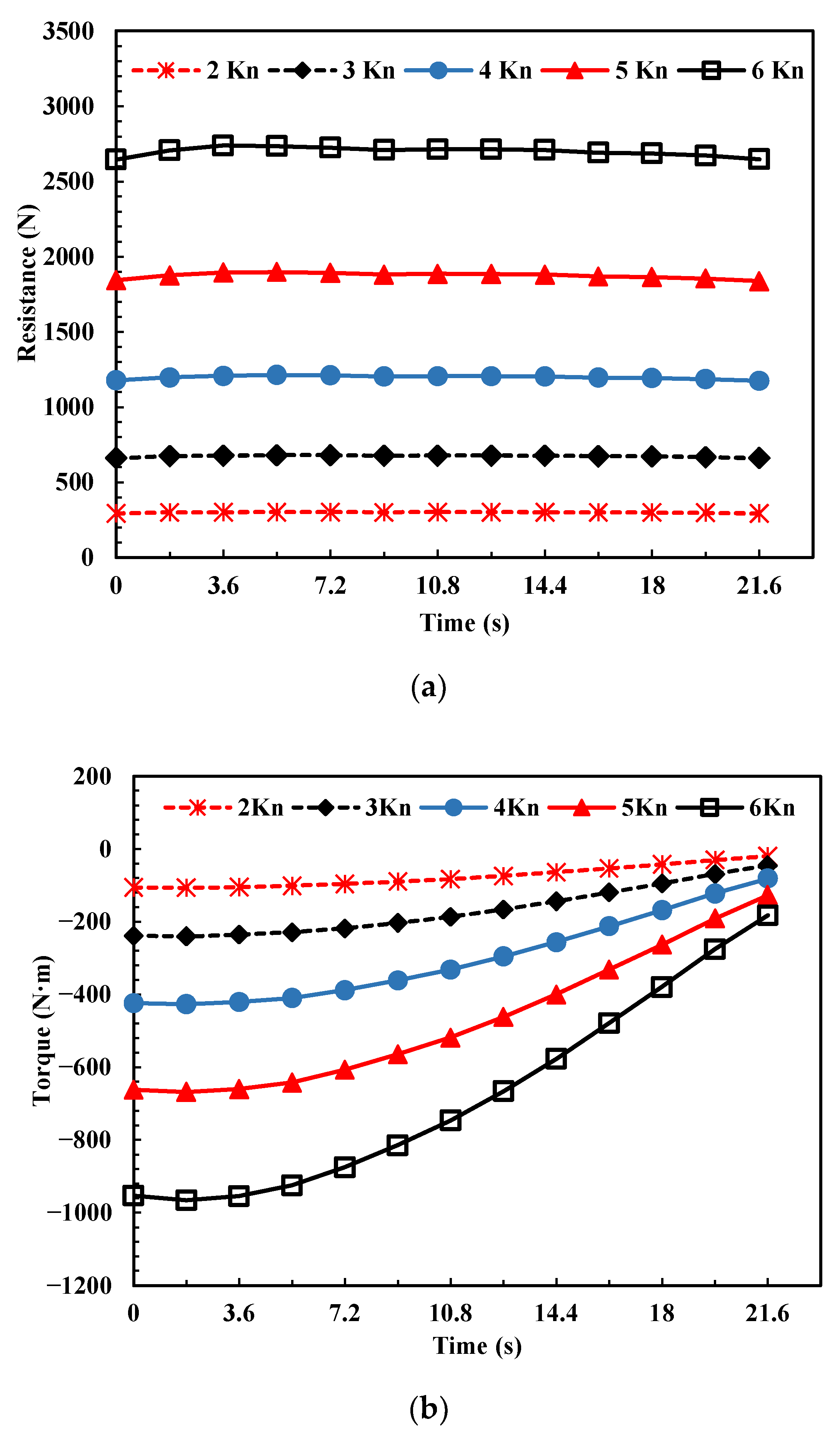
Considering the overall resistance of the foldable arm and the torque rotates around the X- and Y-axes, the optimal motion velocity of the foldable arm is 3 Kn. The simulation results show that the fluid flow around the foldable arm is relatively regular, allowing the foldable arm to maintain a higher level of stability throughout the movement.
(3)
The FSI results show that the maximum directional deformation (Z-axis) in the evaluated cases is relatively small (less than 0.50 mm) and the maximum deformation is along the direction of fluid loading. The maximum equivalent stress of the foldable arm is 578.99 MPa and occurs at the outer edge of the plate where it is hinged to the link.
The investigations have important guiding significance for the optimal posture selection and structural design of the manipulator.

Author Contributions

J.W.: Conceptualization, Methodology, Investigation, Data curation, Formal analysis and Writing—original draft. S.S.: Project administration, Conceptualization, Supervision and Review and editing. W.W.: Super-vision and Writing—review and editing. Y.H. (Yuqing Hou): Validation and Software. Y.H. (Yicang Huang): Validation and Software. All authors have read and agreed to the published version of the manuscript.

Funding

This work was supported by the Fundamental Research Funds for the Central Universities (Grant No. 2042022gf0017).

Institutional Review Board Statement

Not applicable.

Informed Consent Statement

Not applicable.

Data Availability Statement

The data presented in this study are available in this article (tables and figures).

Conflicts of Interest

The authors declare no conflict of interest.

References

  1. Sun, S.; Chen, F.; Zhao, M. Numerical simulation and analysis of the underwater implosion of spherical hollow ceramic pressure hulls in 11,000 m depth. J. Ocean Eng. Sci. 2022, 8, 181–195. [Google Scholar] [CrossRef]
  2. Sivčev, S.; Coleman, J.; Omerdić, E.; Dooly, G.; Toal, D. Underwater manipulators: A review. Ocean Eng. 2018, 163, 431–450. [Google Scholar] [CrossRef]
  3. Capocci, R.; Dooly, G.; Omerdić, E.; Coleman, J.; Newe, T.; Toal, D. Inspection-Class Remotely Operated Vehicles—A Review. J. Mar. Sci. Eng. 2017, 5, 13. [Google Scholar] [CrossRef] [Green Version]
  4. Christ, R.; Wernli, R. The ROV Manual: A User Guide for Remotely Operated Vehicles, 2nd ed.; Elsevier Science: Oxford, UK, 2014. [Google Scholar]
  5. Chang, C.C.; Chang, C.Y.; Cheng, Y.T. Distance measurement technology development at remotely teleoperated robotic manipulator system for underwater constructions. In Proceedings of the 2004 International Symposium on Underwater Technology, Taipei, Taiwan, 20–23 April 2004; pp. 333–338. [Google Scholar] [CrossRef]
  6. Hachicha, S.; Zaoui, C.; Dallagi, H.; Nejim, S.; Maalej, A. Innovative design of an underwater cleaning robot with a two arm manipulator for hull cleaning. Ocean Eng. 2019, 181, 303–313. [Google Scholar] [CrossRef]
  7. Coleman, D.; Ballard, R.; Gregory, T. Marine archaeological exploration of the Black Sea. Proc. Ocean. 2003, 3, 1287–1291. [Google Scholar] [CrossRef]
  8. Fletcher, B. Worldwide Undersea MCM Vehicle Technologies; Space and Naval Warfare Systems Center: San Diego, CA, USA, 2000. [Google Scholar]
  9. Jones, D.O.B. Using existing industrial remotely operated vehicles for deep-sea science. Zool. Scr. 2009, 38, 41–47. [Google Scholar] [CrossRef]
  10. Mitra, A.; Panda, J.; Warrior, H. Experimental and numerical investigation of the hydrodynamic characteristics of Autonomous Underwater Vehicles over sea-beds with complex topography. Ocean Eng. 2020, 198, 106978. [Google Scholar] [CrossRef] [Green Version]
  11. Li, Y.-W.; Wang, J.-S.; Wang, L.-P.; Liu, X.-J. Inverse dynamics and simulation of a 3-DOF spatial parallel manipulator. In Proceedings of the IEEE International Conference on Robotics and Automation, Taipei, Taiwan, 14–19 September 2003; Volume 3, pp. 4092–4097. [Google Scholar] [CrossRef]
  12. Kuriyama, Y.; Yasuda, Y.; Yano, K.I.; Hamaguchi, M. Liquid container transfer control by hybrid shape approach for 6dof manipulator. In Proceedings of the SICE Annual Conference, Takamatsu, Japan, 17–20 September 2007; pp. 3069–3072. [Google Scholar] [CrossRef]
  13. Huang, M.F.; Qian, G.; Luo, W.Z.; Chen, L.L.; Jin, G.C. Dynamics Analysis and Simulation of one-DOF Parallel Manipulator. Adv. Mater. Res. 2011, 422, 47–50. [Google Scholar] [CrossRef]
  14. Kazakidi, A.; Tsakiris, D.P.; Angelidis, D.; Sotiropoulos, F.; Ekaterinaris, J.A. CFD study of aquatic thrust generation by an octopus-like arm under intense prescribed deformations. Comput. Fluids 2015, 115, 54–65. [Google Scholar] [CrossRef]
  15. Kolodziejczyk, W. The method of determination of transient hydrodynamic coefficients for a single DOF underwater manipulator. Ocean Eng. 2018, 153, 122–131. [Google Scholar] [CrossRef]
  16. Afra, B.; Delouei, A.A.; Tarokh, A. Flow-Induced Locomotion of a Flexible Filament in the Wake of a Cylinder in Non-Newtonian Flows. Int. J. Mech. Sci. 2022, 234, 107693. [Google Scholar] [CrossRef]
  17. Afra, B.; Karimnejad, S.; Delouei, A.A.; Tarokh, A. Flow control of two tandem cylinders by a highly flexible filament: Lattice spring IB-LBM. Ocean Eng. 2022, 250, 111025. [Google Scholar] [CrossRef]
  18. Huang, S.; Wang, C.; Wang, S.Y. Application and comparison of different turbulence models in the computation of a propeller’s hydrodynamic performance. J. Harbin Eng. Univ. 2009, 30, 481–485. [Google Scholar] [CrossRef]
  19. Cheng, L. Hydrodynamic Interactions Between Two Bodies. J. Hydrodyn. 2007, 19, 784–785. [Google Scholar] [CrossRef]
  20. Song, F.X. Shape Design for a Hybrid-Driven Underwater Vehicle Based on CFD; Tianjin University: Tianjin, China, 2011. [Google Scholar]
  21. Zhang, L.; Wang, Z. A block LU-SGS implicit dual time-stepping algorithm for hybrid dynamic meshes. Comput. Fluids 2004, 33, 891–916. [Google Scholar] [CrossRef]
  22. Wu, L.; Li, Y.; Su, S.; Yan, P.; Qin, Y. Hydrodynamic analysis of AUV underwater docking with a cone-shaped dock under ocean currents. Ocean Eng. 2014, 85, 110–126. [Google Scholar] [CrossRef]
  23. Hong, L.; Fang, R.; Cai, X.; Wang, X. Numerical Investigation on Hydrodynamic Performance of a Portable AUV. J. Mar. Sci. Eng. 2021, 9, 812. [Google Scholar] [CrossRef]
  24. Hong, L.; Wang, X.; Zhang, D.; Xu, H. Numerical Study on Hydrodynamic Coefficient Estimation of an Underactuated Underwater Vehicle. J. Mar. Sci. Eng. 2022, 10, 1049. [Google Scholar] [CrossRef]
  25. Subudhi, B.; Morris, A. Dynamic modelling, simulation and control of a manipulator with flexible links and joints. Robot. Auton. Syst. 2002, 41, 257–270. [Google Scholar] [CrossRef]
  26. Zeng, Y.-S.; Yao, Z.-F.; Huang, B.; Wang, F.-J.; Wu, Q.; Xiao, R.-F.; Wang, G.-Y. Numerical studies of the hydrodynamic damping of a vibrating hydrofoil in torsional mode. J. Hydrodyn. 2021, 33, 347–360. [Google Scholar] [CrossRef]
  27. Huang, J.G.; Sun, Y.L.; Wang, T.M.; Lueth, T.C.; Liang, J.H.; Yang, X.B. Fluid-structure interaction hydrodynamics analysis on a deformed bionic flipper with non-uniformly distributed stiffness. IEEE Robot Autom. Lett. 2020, 5, 4657–4662. [Google Scholar] [CrossRef]
  28. Hassan, S.N.H.; Yusof, A.A.; Tuan, T.B.; Saadun, M.N.A.; Ibrahim, M.Q.; Nik, W.M.N.W. Underwater manipulator’s kinematic analysis for sustainable and energy efficient water hydraulics system. AIP Conf. Proc. 2015, 1660, 070112. [Google Scholar] [CrossRef]
Figure 1. Three postures of the designed foldable arm: (a) α = 0° (b) α = 90° and (c) α = 180°.
Jmse 11 01395 g001
Figure 2. Geometry model of the foldable arm: (a) diagram of geometric dimensions (b) unfolding process.
Jmse 11 01395 g002
Figure 3. Experimental setup in the recirculating water tank: (a) the designed measuring devices and (b) the geometry of the measuring rod.
Jmse 11 01395 g003
Figure 4. Hydrodynamics performance of underwater foldable arm with different velocities (2.5 Kn and 3.0 Kn) (a) Stage 1, (b) Stage 2, and (c) Stage 3. N represents the resistance, and M represents the bending moment.
Jmse 11 01395 g004aJmse 11 01395 g004b
Figure 5. Mesh model of the foldable arm.
Jmse 11 01395 g005
Figure 6. Pressure distribution of the foldable arm at three different static postures.
Jmse 11 01395 g006
Figure 7. Deviation analysis between the simulation and experiment results at three static postures (3.0 Kn). Rs is the resistance obtained by simulation. Re denotes the resistance obtained by experiment. Ts is the torque obtained by simulation and Te is the torque obtained by experiment.
Jmse 11 01395 g007
Figure 8. The resistance and torque acting on the foldable arm at different velocities during the unfolding process by the CFD simulation. (a) represents the total resistance of the foldable arm. (b) represents the torque of the foldable arm rotating around the X-axis. (c) represents the torque of the foldable arm rotating around the Y-axis.
Jmse 11 01395 g008aJmse 11 01395 g008b
Figure 9. Pressure distribution of the foldable arm during the unfolding process.
Jmse 11 01395 g009
Figure 10. Flow field distribution on planes at different locations during the unfolding process of the folding arm at (a) 0 s (b) 10.8 s and (c) 21.6 s.
Jmse 11 01395 g010aJmse 11 01395 g010b
Figure 11. Flow chart of two-way FSI solution technique.
Jmse 11 01395 g011
Figure 12. Directional deformation (Z-axis) of the foldable arm during the unfolding process.
Jmse 11 01395 g012
Figure 13. Equivalent (von-Mises) stress of the foldable arm during the unfolding process.
Jmse 11 01395 g013
Table 1. Average resistance and torque of the foldable arm at three postures in experiments.
Velocity (Kn)Stage 1Stage 2Stage 3
Resistance (N)2.5480.60488.68485.22
3.0695.28709.56701.70
Torque (N·m)2.5238.42169.6261.09
3.0332.97259.8485.19
Table 2. Boundary conditions of CFD analysis.
Boundary ConditionUnitBoundary Value
Turbulence Model-SST k ω
Flow Domain Dimensionsmm20,000 × 18,400 × 23,400
Flow VelocityKn3.0
Flow Direction-Z
Mesh NumberM3.59
Mesh Form-Polyhedron + Quadrilateral
Inlet-Velocity Inlet
Outlet-Pressure Outlet
Exterior Domain Surface-Wall
Table 3. The resistance and torque of the foldable arm at three static postures in CFD simulations.
Stage 1Stage 2Stage 3
Resistance (N)698.06689.40645.26
Torque (N·m)331.10275.6481.35
Table 4. Properties of the utilized aluminum alloy material.
Material ParametersValueUnit
Density
Young’s Modulus
2770
7.1 × 10¹⁰
kg/m3
Pa
Poisson’s Ratio
0.33(-)
Tensile Yield Strength
2.8 × 10⁸Pa
Compressive Yield Strength
2.8 × 10⁸Pa
Tensile Ultimate Strength
3.1 × 10⁸Pa
Disclaimer/Publisher’s Note: The statements, opinions and data contained in all publications are solely those of the individual author(s) and contributor(s) and not of MDPI and/or the editor(s). MDPI and/or the editor(s) disclaim responsibility for any injury to people or property resulting from any ideas, methods, instructions or products referred to in the content.

