1. Introduction
Recently, there have been many different semi-submersible floating offshore wind turbine designs introduced to public attention [
1]. As with every new technology, it is uncertain which option is the best, only with time will natural evolution strike out inefficient designs and standardize the invention to some extent. Regarding semi-sub FOWT, some configurations have already been well established in the industry, such as tri-column design and off-center turbine placement, as seen in commercialized projects. However, other parts of the semi-sub design are still highly debated, such as how the pontoon should look and the optimal column shape.
Among current and planned projects by different companies and research teams (
Figure 1), there are V-shaped (Fukushima Shinpuu) [
2], T-shaped (Bassoe T-floater) [
3], above-water pontoons (Gusto Tri-Floater old version) [
4], tubular joints (WindFloat) [
5] and ship-like hull pontoons (DeltaFloat) [
6], platforms with and without above-water bracing (EOLFI floater [
7], Fukushima Shinpuu), platforms with bracing bigger than pontoon (SanXia YingLing Hao) [
8], etc. It is evident that every design team drafts their design with particular constraints and necessities in mind; however, as most are made by for-profit companies, not much of their thought process is shared with the general public.
As researchers, we take the liberty to analyze and compare them without bias. With so many varieties, it is clear that some are to be outlived by the more efficient. The parts specifically looked at in this paper are the different pontoons, columns and, to a lesser extent, bracing configurations.
Pontoon and bracing have a practically similar purpose—to hold the columns together for them to make up a platform. In designs such as wind floats, they are practically the same, the only difference being the pontoon is located underwater, while the bracing is above water. Bracing also provides a way for workers to walk between the columns.
The pontoon is filled with ballast and thus brings the platform’s center of gravity down; if its vertical footprint is big, it also acts as a heave-damping plate. Sometimes, it can also provide buoyancy as will be described later.
2. Methodology
To compare different pontoons, 10 modifications of a base platform A were created in ANSYS SpaceClaim, shown as the shapes B to K in
Figure 2, and a cylindrical columns shape L. The original triangular ring pontoon platform is an updated version of TaidaFloat [
9], a prototype platform to be used in Taiwan strait. While TaidaFloat pontoons can be fully functional (provide buoyancy) or partially functional (permanently ballasted), they will be considered only partially functional to remove the influence of wildly varying buoyancy between the different pontoons. The other dimensions including all column dimensions and overall length and width are the same among designs, as shown in
Table 1. The platform supports a 15 MW IEA turbine [
10,
11], with the following characteristics shown in
Table 2. The platform also takes some ballast in columns for use in a dynamic stabilization system and to achieve the desired draught.
For every configuration, turbine, ballast and platform assembly weight characteristics including mass moments of inertia were calculated using ANSYS Mechanical, and they are shown in
Table 3.
Every design case should be analyzed from the following viewpoints:
Strength,
Stability,
Costs, and
Practicality.
This paper focuses on strength and cost only. Stability and practicality may be tackled in future research.
Nowadays, the common approach is to analyze the structural strength of a large number of designs with FEM. The ANSYS Mechanical Static Structural module was used for this purpose here. Hull weight and mass moments of inertia were calculated with a framed, ship-like, inner structure. The inner structure is based on the original inner structure for configuration A, slightly modified to fit the shape in other cases. It is shown in
Figure 3.
As the first step, all the configurations were subjected to static loads—gravity, water pressure (fully ballasted pontoon condition), turbine assembly weight and a 0.1 G acceleration in the x and y directions to approximately account for the wave loads.
It is unsurprising that every configuration successfully withstands these static loads, with no important difference between different designs. An example of the result is shown in
Figure 4.
The actual difference among the 12 pontoon designs can only be seen during its operation in the rough sea, with dynamic loads. According to ABS Rules [
12], and other major class societies’ rules [
13,
14,
15], offshore structures’ dynamic performance is to be analyzed with different DLP (Dominant Load Parameters) and DLC (Design Load Cases). They represent a comprehensive array of parameters such as wind, loading, waves applied together in the most unfavorable combinations (DLC), and their effect on particular structure parts and modes of deformation (DLP).
A common practice for a FOWT strength analysis is similar to oil and gas platforms with the added complexity of turbine–wind interaction:
Environmental conditions of the planned installation site are determined. This usually involves placing a buoy on-site at least one-two years in advance. A longer time is preferred, as 50 year return conditions will have to be extrapolated for the extreme weather survival load cases. As FOWT are unmanned, a less-conservative 50 year return period is used as opposed to 100 years for oil and gas.
After an initial design geometry and mass distribution are ready, the platform is subject to hydrodynamic response analysis, which provides Response Amplitude Operators (RAO) for 6 degrees of freedom. The motion and acceleration RAO peak values provide guidance on which wave conditions could impart maximal stress to the platform; the most dangerous wave condition that is expected to occur is referred to as the design wave. Then, a pressure distribution on the hull below the surface can be acquired and mapped onto a more detailed structural model for subsequent FEA. The RAO analysis and load mapping are usually performed with software, e.g., Ansys AQWA used in this paper.
Different from oil and gas, wind turbines impart a huge moment load onto the top part of the floater. When the mooring system and a turbine have been designed, wind turbine and mooring line loads can be found using coupled wind–wave simulation software, such as OrcaFlex used in this paper, and applied as loads in FEA software.
The hydrodynamic loads, wind and mooring loads, equipment weight and wave-induced acceleration are applied to the global FE model, including hull modelled as shell elements and scantling modelled as beam elements. For a detailed investigation of areas of interest and fatigue analysis, a set of local models are made with hull and girders represented by shell elements.
There is different software for FEA and techniques to constrain the model and map the loads. The authors map loads from AQWA directly to Ansys Mechanical and use springs at the place of moorings with constraints at the far end. Finally, a stress distribution can be obtained for assessment with the maximum stress design criteria, as shown in
Figure 5.
However, this process requires a complete design for internal stiffeners, wind turbine model, ballast distribution, and most importantly, a complete mooring system and many iterations loops to obtain the result; therefore, it is rare to see different floaters directly compared to each other. As such, a simplified approach is used here to compare the 12 floater shapes and find out their advantages rather than obtain a precise maximum stress value.
For a structure such as a FOWT floater, the matrix of DLP and DLC combinations reaches more than one hundred cases. For 12 pontoon configurations analyzed in this paper that would be more than a thousand cases to investigate. However, not all cases are equally important; here, we use engineering judgement and compare 12 shapes’ performances at critical DLPs and the roughest wave load DLC. This method was employed with great success to reduce the number of analyses when investigating a single platform under different loads [
16]. This study is similar in that it picks out separate DLPs to look at structural responses, but the cases are simplified as many different platforms are analyzed and compared with each other. The flowchart for the process is shown in
Figure 6 The mesh size employed was 600 mm, which corresponds to frame spacing. Case A full FEA result shown in
Figure 7.
As we are looking at stress induced only by a particular DLP, we need to isolate the load from others when we perform the analysis. The DLP concept is not sensitive to load origin (e.g., wave load, turbine load or impact load), but only to the force direction; therefore, we apply isolated forces or pressures for each DLP, and the magnitudes are chosen to represent pressure caused by a wave of 35 m height, just reaching the platform top deck.
The most critical is arguably DLP 1; when the wave front is along the platform’s
X axis, then one side column is on the wave top, another side column in the crest, and the main column is at the middle height, as shown in
Figure 8. Difference in buoyancy forces between the two columns produces a twisting moment on the pontoons linked with the main column, potentially breaking them. This condition is simulated by the application of two forces in opposing directions on the top decks of side columns. The boundary condition is a fixed support at the main column top—farthest from the area of interest, which is the plane defined by the two side columns.
DLP 2, shown in
Figure 9, is when the wave front approaches along the
Y axis, the main column on the wave top and both side columns in the crest, or vice versa. This condition is simulated by applying two upward forces at side columns and a downward force of double magnitude at the main column; a simple support condition is applied to a vertical line on the front side of the main column, as it is a rigid, non-deformed region in this case.
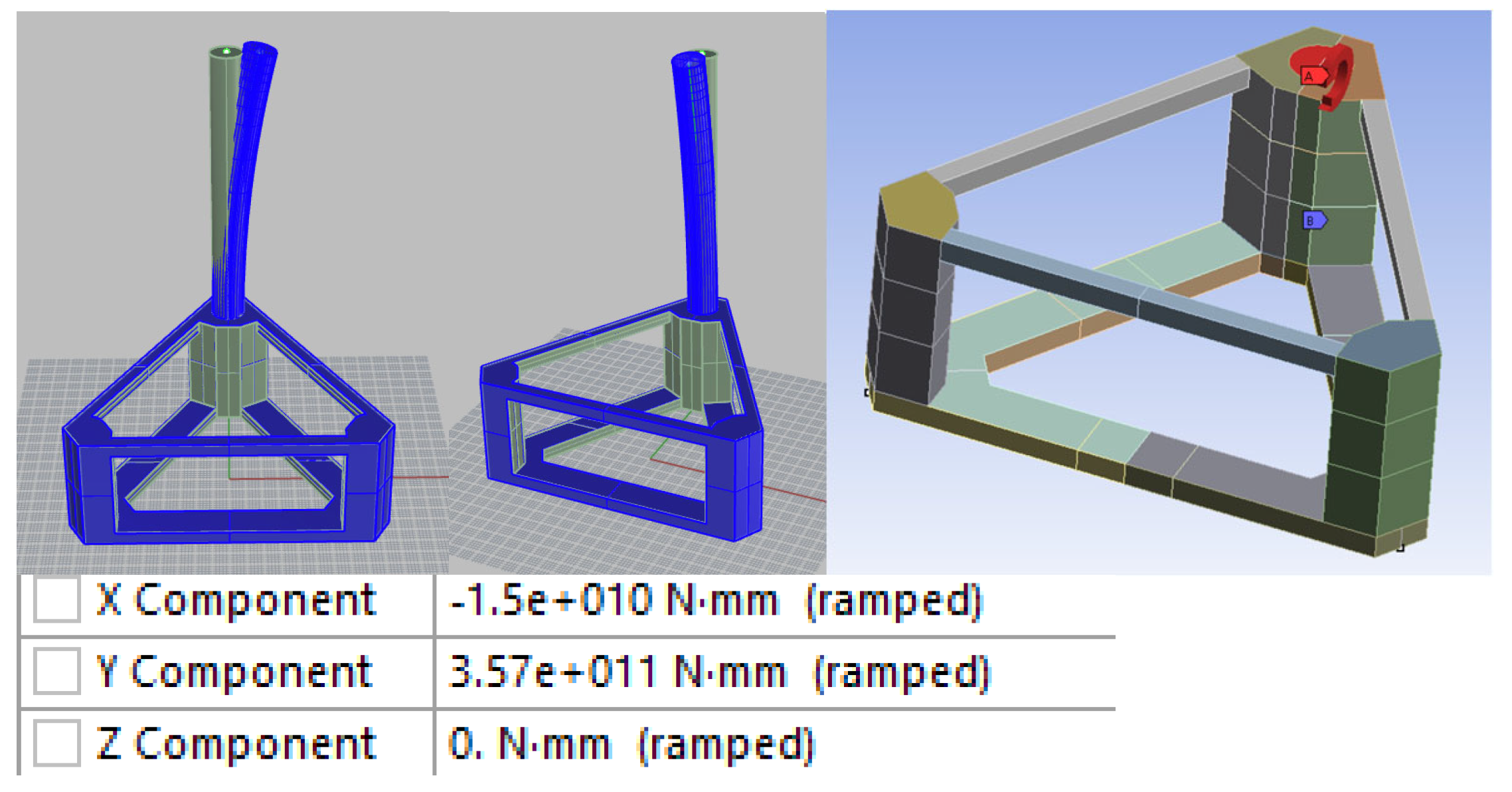
DLP 3 is bending of the main column, possibly induced by wind turbine load, as shown in
Figure 10. This condition is simulated by applying a moment to the circular turbine foundation on the top of the main column. The moment is taken from an OrcaFlex typhoon Extreme Sea State simulation described in [
17]; the boundary condition is three simple supports at column bottoms (fairlead position), far from the area of interest.
3. Pontoon Design
3.1. Floaters Comparison
For this part of this study, simplified models were used, which had a uniform plate thickness of 30 mm and no reinforcement, except for bulkheads. The force application areas were kept rigid using coupled multi-point constraints. The adequacy of this simplification was demonstrated in a previous study [
9]. By comparing the stress distributions of a full-detail model in
Figure 7 and the subsequent results, it can be seen that the stress concentration areas are the same (joints between columns, pontoons and bracings; bracings plating, the lowest belt of column plating), thus the simplified method and models produce credible results for this comparison study.
DLP 1: Faced with a beam wave-induced twist, floaters with a pontoon connecting every two columns resist the load well, while floaters without all three pontoons or with an intersection in the middle show large areas of stress concentrations (cases F, G, H, and K). Because the structure is not rigid enough, a small force is able to give birth to a large moment, due to a long moment arm which is the distance between the side and main column (cases F, G, and K) or a column and a central intersection in case H. Cases D, E, and I showed a moderate result, withstanding the forces with small stress concentrations in the connections between structural members. Cases A, B, C, and J showed the best results due to their ring pontoon structure.
Interestingly, case L did not exhibit the same high stress around the pontoon intersection as a similar case H; this can be attributed to another column in the middle reinforcing the structure in case L, as well as the rounded corners. However, when faced with shear (DLP 2), case L fails with 354% higher max stress when compared to case A, due to the central column location. Under this DLP, the pontoons connected in the middle can be seen as moment arms for large moments to act.
In cases where the columns were only connected with pontoons, stress is much higher, than where both pontoons (in the bottom) and bracings (on top) connect the columns.
DLP 2: Generally, the configurations that were resilient to DLP 1 had also withstood DLP 2 well, albeit with generally higher maximum stress, with notable exceptions in cases F and L. As seen in
Figure 14, in these two cases, the moment around the transverse (
Y) axis created large stresses in longitudinal members, cases K and L were able to withstand that due to their pontoon being twice as high as compared to other configurations. This effect is very apparent in case E—even as the max stress did not get much higher, the stress concentration area became very large around the longitudinal pontoon. If the platform is positioned to face the most probable strong wind direction, DLP 2 is the most probable mode of loading and must be treated with sufficient importance.
At the same time, the lack of transverse bracing had no impact on this load case, allowing cases K and G to have lower stress than in DLP 1, which might have influenced some real-life prototype designers motive to remove transverse bracing and pontoon.
DLP 3: Unique for Floating Wind, DLP 3 simulates wind turbine loading detached from other loads. Except for cases A and C, all others showed much higher stresses under this load. As seen in
Figure 15, if made without bracing, every platform is going to break.
This happens because the wave force is acting on the column top, while a pontoon supports it only at the bottom, thus the column height becomes a huge moment arm.
In particular, all configurations with Y-shaped pontoons performed particularly bad, with the Y-shaped bracing without underwater pontoon being the worst. This is because of two reasons: they have a weak point at the middle intersection and they only have one pontoon going to each of the columns, instead of two pontoons connecting each column. At the same time, Y-pontoons use equal amount of steel to manufacture the three pontoons, as the ring pontoon configuration. These characteristics make Y pontoons an uneconomical option and they should be avoided.
Case C showcases how to best withstand wind turbine load—a tall and narrow pontoon is much better than a conventional flat and wide. Using the same amount of steel, stress is reduced. However, such configuration’s drag coefficient might be much larger. Case J with tubular bracing showed good results overall, but with some spiky stress concentrations in connection regions due to members intersecting at sharp angles. This could be avoided if 90 degrees connections were used.
3.2. Bracing Design
Given the large stresses found, let us discuss wind turbine and bracing in detail. During normal operation and even during typhoon conditions when the turbine blades still receive wind loads, the turbine will generate a significant bending moment on the supporting structure. This loading consists of three force components and three-moment components, with the most prominent being the fore-aft bending moment and the vertical force that includes the weight of the turbine itself.
Figure 16 shows the stress distribution in the platform, which highlights the importance of the bracing, especially in the connection parts, as they experience the highest stresses.
As first described by Jonkman [
18], the wind turbine installed on a FOWT can generate several times the moment on its support that the same turbine would generate on land. Thus, it is essential that the bracing is designed to withstand these loads to ensure the platform can fulfil its primary purpose of supporting the turbine. Fatigue life is also significantly reduced under these loads, further emphasizing the importance of robust bracing design. Future research will investigate the impact of wind turbine moments on bracing in more detail, and this will be the subject of an upcoming paper.
Note that bracing can be structurally critical. The worst structural failure in a semi-submersible may be the Alexander Kielland accident in 1980, which resulted in the capsizing of the floater [
19]. The disaster started from a fatigue crack in bracing. The damaged bracing caused the column to break off from the platform. Consequently, the semi-submersible capsized.
A braceless V-shaped semi-sub FOWT was investigated in 2015 [
20]. It was argued that braceless configuration reduces fatigue stress because it removes the fatigue-prone joints altogether, citing successful examples of braceless oil platforms. We were unable to verify the success of such platforms and they were not referenced and most crucially, the authors did not consider the wind turbine bending moment, which makes a huge difference between FOWT and an oil rig. Fukushima Shinpuu was a cited example of a braceless FOWT. This semi-sub concept was retired in 2020 due to “obvious structural failures” [
21]. No post-decommission reports were published, but it could be deduced using this paper’s analysis that fatigue cracks might have developed in the pontoons as they had to bear the wind turbine moment in the absence of bracing.
Figure 17 plots a relationship between the number of connecting members and average stress levels in the aforementioned configurations analyzed under DLP 1. High average stress is directly related to fatigue in the case of FOWT as this stress will be caused by highly cyclic wave and turbine loads. Connections are the sum of bracings and pontoons of a platform. It was found that the number of pontoons does not have such a significant impact in this case, as bracings; a trend can be seen that the fewer bracings there are, the higher the average stress.
While it might be obvious to experienced engineers, FOWT is a new area with engineers coming from different industries, who, as can be seen from many unsuccessful designs, might be unaware of unique design requirements imposed by the wind turbine, and this paper aims to prevent the structural failures from happening, as it might make FOWT a less trusted technology.
Table 4 shows that platforms with similar hull weights can have vastly different structural performances. Although their average stress is not significantly different, the maximum stress varies greatly under the same load (DLP 1). This indicates that some shapes have severe stress concentration areas compared to others.
The best and worst performers in each DLP (column) are denoted by green and red colors, respectively. Interestingly, some platforms are the best in one category but the worst in another (cases H and L).
The advantage of configurations with many structural members is that they perform sufficiently well under different DLPs, which is important since conditions at sea and during transportation can be unpredictable. Configurations can withstand particular DLPs with lower stress than full bracing and pontoon configurations, but they may fail under other DLPs; therefore, all practically possible DLPs should be analyzed when considering the initial structure.
Note that the exact value of maximum stress may differ if a high-detail model were analyzed, but the table still provides a useful comparison of the structural performances of different platform shapes.
The strength of a structure can be measured by its average stress. A shape called J with tubular joints connecting columns is the strongest performer, with well-distributed loads. However, making tubular joints is complicated because they are round and need to connect to straight walls and each other. This causes high stress in connection regions, but this is not a problem if the columns, pontoon, and bracing intersect at right angles and their internal stiffeners align perfectly.
Although J is strong, it is heavier compared to other shapes with smaller pontoon and bracing configurations. The lightest shape is H with Y-shaped bracing and no pontoon, but it has high stress of almost 1000 MPa under DLP 1. This means it would need to be strengthened a lot, which negates its weight economy. The shape L with a circular central column is excluded from the weight comparison because it is a different breed of structure.
An experiment was done on J by increasing the tubular joints thickness to 60 mm, making a new shape called J2. Its maximum stress under DLPs 1 and 2 was reduced to below case A’s stress, and DLC 3 stress could be made equal to A’s stress with connection reinforcement. However, J2 was heavier, weighing 6124 tons, which is 53% heavier than shape A, which shows that just increasing thickness without changing the shape is not an economical solution.
4. Column Design
In most of the cases presented above, the columns of the semi-submersible floater are hexahedral, while in others they are cylindrical. This raises a question about why the hexahedral shape was chosen. To understand this, it is important to know that the columns of a semi-submersible floater serve three main functions:
Changing any aspect of the column to improve its performance in one function will affect its performance in the other two functions as well. Therefore, a complex balancing process is required to optimize the design of the columns.
At the moment, the FOWT industry has two types of column designs, as shown in
Figure 18 and
Figure 19:
Round (e.g., WindFloat designed by Principal Power) [
5].
Square (e.g., Shinpuu designed by Fukushima Project) [
22].
Table 5 lists the advantages and disadvantages of circular and polygonal cross-section columns. Since they are two opposite shapes, it makes sense that the optimal design would be somewhere in between. To create a column that approximates the circular shape while only using straight plates, a polygonal cross-section column is used.
For TaidaFloat, which has three columns and three pontoons, one column needs to connect to two pontoons. After considering various options, a hexagonal shape is proposed as the most suitable design. To ensure that the stiffeners of the pontoons fit the stiffeners of the column perfectly, two of the column sides are made to be the same width as the pontoon. Other sides are chosen to be integers and dimensions are chosen so that the main column-to-side-column section area ratio is the same as for circular columns.
Both tetrahedral (square section) and hexahedral columns share the simplicity of manufacturing advantage. There is no equipment to make 14 m-diameter pipes with one seam (at least in Taiwan), so cylindrical and polyhedral columns are all fabricated by welding numerous steel plates together. In the case of polyhedral columns, steel plates can be welded automatically into one wall section while lying flat, and then the sections are easily assembled to form a column. In the case of cylindrical columns, every plate would have to be bent first, requiring equipment and processing time; moreover, plates could not be assembled into sections while lying flat because of their curvature, they would have to be placed vertically, supported by cranes, then welded manually or semi-manually, taking not only much more time, equipment and workers to complete the assembly, but also the quality of manual welding is inherently inferior to automatic welding; weld strength is particularly important for deeply submerged structures. All this equally applies to the internal stiffeners, which would also have to be bent and welded onto the shell. Finally, curved structures are more difficult to store and transport. Thus, it is evident that with the same steel weight, cylindrical columns are more expensive in manufacturing, thus the exact percentage of the cost difference is subject to local shipyard procedures and equipment.
However, the easy-to-manufacture polyhedral shapes have another perceived weakness—stress concentrations. To check for them, finite elements analysis was conducted with turbine weight and gravity as loads. A stress concentration was indeed found in
Figure 21, but only in corners where the bracing and pontoon connect to the column’s inner side, and its value of 262 MPa is acceptable for the preliminary structure design stage. This corner can easily be reinforced during subsequent design.
In
Figure 22, the original TaidaFloat is shown along with two new hexagonal variants: To determine the final shape, an international expert group consisting of twenty specialists from the industry and academia were asked to vote. Interestingly, half of the votes went to the original circular platform, and half went to the hexagonal platform concept.
After careful consideration, the purple hexagonal shape was chosen—as this platform is designed to be mass-manufactured, construction ease is more important than a slightly better wave response. As this platform is made with flat plates and the pontoon is perpendicular to the column side, it retains all the benefits of the square section column from
Table 1, at the same time the cons are not as bad as for the full square shape, wave impact and drag are still less.
Following the principle of a close collaboration with the shipyard, the platform dimensions were changed to fit the shipyard’s steel plate dimensions and welding equipment sizes, e.g., pontoon and bracing height were reduced from 4 to 3.75 m to fit 3.8 m-width steel plates produced by Taiwanese steel mills.
After all the modifications, the latest version TaidaFloat characteristics are as in
Table 7.
5. Discussion
In this section, we will discuss the findings of this study and highlight the key factors that need to be considered when designing a floating offshore wind turbine (FOWT) platform.
This study analyzed 13 different platform configurations, under three (3) different design load parameters (DLP). The objective was to identify the most cost-effective and structurally efficient platform design that can withstand the environmental loads and stresses exerted on the FOWT platform.
Based on the analysis, platform E with a T-shaped pontoon provides the most cost-effective solution under the assessed DLC and DLP. It is robust, relatively cheap, and easy to fabricate. However, considering that FOWT floaters are a relatively new type of structure with a history of failures, a safer platform configuration might be preferred for a new 15 MW platform. In this case, the material economy is not as important as the safety of the platform. Platforms A and C, both ring pontoons with full bracing, are considered the safest configurations. While they are structurally similar, they may have different hydrodynamic performance and RAO, which requires further investigation.
Additionally, it is important to consider the draft of the platform and its relation to the pontoon. Typically, pontoons are permanently filled with water before exploitation to counteract outside water pressure. However, in the case of a floating offshore wind turbine, the emptied pontoon provides floatation during the transportation and installation stages. The internal structure of the pontoon needs to be strong enough to support water pressure exceeding 200 kPa. However, the mass of all this reinforcement helps bring the pontoon’s center of gravity further down, improving stability. It is cheaper to add weight by increasing pontoon steel parts thickness than by pouring concrete inside when considering added operational costs. The added buoyancy is crucial when entering and exiting shallow ports, allowing platforms (cases A–E) to be assembled and serviced closer to their deployment area, while cases G–K are limited to very deep ports or have to use temporary floatation modules.
Finally, the hexahedral column shape is chosen for TaidaFloat by the design team as it combines the best attributes of cylindrical and square shapes. The ease of construction with flat steel plates makes the square shape stand out.
One potential drawback of the hexahedral column shape chosen for TaidaFloat is that it may not be as efficient in terms of space utilization compared to other shapes. Future research could explore ways to optimize the design to maximize space utilization without compromising on other performance metrics.
Another area for future research is the long-term durability, fatigue life and maintenance requirements of these designs. As FOWT floaters are relatively new structures, there is still much to learn about their long-term behavior and performance in real-world conditions. Continued monitoring and research can help to identify any potential issues and optimize the design for improved durability and longevity.
There are some limitations to this study, as the method was simplified from the full-cycle design analysis to analyze many floaters. Additionally, the shapes analyzed are simplified, and there exist no special arrangements to make them withstand the loads better. It would be better to design and compare the floaters in full detail including the joints and stiffeners; however, it might take approximately a year for every floater.
6. Conclusions
In conclusion, designing an efficient and cost-effective floating offshore wind turbine platform requires consideration of various factors such as hydrodynamic performance, structural stability, and operational costs. Based on the research in this study, the design team chose the following for TaidaFloat:
A hexahedral column, as it combines the best attributes of cylindrical and square shapes, and uses flat steel plates, making the construction much easier and faster.
A full-ring pontoon configuration for low stresses under all load conditions and the ability to control draught by ballasting.
The ring bracing configuration to prevent stress concentrations and fatigue damage at connection points and efficiently distribute the wind turbine’s torque across the structure.
The findings of this study can provide valuable insights for future FOWT platform design and development. Further research is necessary to investigate other potential platform shapes and configurations and optimize their performance.


