Abstract
In this study, the tail-slapping behavior of an oblique water-entry projectile is investigated through high-speed photography technology. The experimental images and data are captured, extracted and processed using a digital image processing method. The experimental repeatability is verified. By examining the formation, development and collapse process of the projectile’s cavity, this study investigates the impact of the tail-slapping motion on the cavity’s evolution. Furthermore, it examines the distinctive characteristics of both the tail-slapping cavity and the original cavity at varying initial water-entry speeds. By analyzing the formation, development and collapse process of the cavity of the projectile, the influence of the tail-slapping motion on the cavity evolution is explored. Furthermore, it examines the evolution characteristics of both the tail-slapping cavity and the original cavity under different initial water-entry speeds. The results indicate that a tail-slapping cavity is formed during the reciprocating motion of the projectile. The tail-slapping cavity fits closely with the original cavity and is finally pulled off from the surface of the original cavity to collapse. In addition, as the initial water-entry speed increases, both the maximum cross-section size of the tail-slapping cavity and the length of the original cavity gradually increase. With the increase in the number of tail-slapping motions, the speed attenuation amplitude of the projectile increases during each tail-slapping motion, the time interval between two tail-slapping motions is gradually shortened, the energy loss of the projectile correspondingly enlarges, and the speed storage capacity of the projectile decreases.
1. Introduction
The formation of a cavity upon the entry of a high-speed projectile into the water is highly beneficial in reducing the fluid drag during its underwater movement, which is of great significance for improving the underwater motion distance and stability of the projectile. However, during the process of water entry, the perturbed projectile often periodically collides with the cavity wall, that is, the tail-slapping motion occurs. The tail-slapping process is often accompanied by the change of cavity structure, the impact of jet flow on the cavity wall, projectile deflection and the occurrence of projectile reciprocating motion, which has a great influence on the evolution characteristics of the water-entry cavity and the stability of the underwater movement. Therefore, researching the tail-slapping motion of the water-entry projectile problems is necessary, which will contribute to the study of the dynamic stability mechanism of water-entry objects. This research will provide a certain reference to the dynamic stability mechanism of water-entry objects.
In recent years, there has been extensive and in-depth research on water-entry problems, which lays a good foundation for the development of the problems of the tail-slapping motion of the water-entry.
Lee et al. [1] put forward a method to simulate the generation and collapse of cavities, laying the foundation for cavity dynamics. In that year, they also developed a pressure wave prediction model suitable for various projectiles (Lee et al. [2]).
Savchenko et al. [3] utilized high-speed photography technology to investigate the characteristics of cavity formation during high water-entry velocity.
Cameron, P. J et al. [4] studied the cavity shape during water entry through experiments and quantitatively described the evolution of cavity shape. Erfanian M R et al. [5] carried out both experimental and simulation studies to study the low-speed water-entry process of spherical-nose objects. H. Forouzani et al. [6] simulated the supercavitation dynamics and planing force through two mathematical models based on experiments and established the motion equation of a supercavitating projectile. Jiang et al. [7] investigated the drag characteristics and flow physics of ventilated supercavitating objects with two different forebodies and three different rear bodies through cavitation tunnel experiments.
Hong et al. [8] conducted simulations to analyze the influence of the impact speed and aeration effect on slamming loads for a cylinder with a flat bottom. Chen et al. [9] investigated the water-entry characteristics of projectiles with different nose shapes, high-speed impact speeds and entry angles. Li et al. [10] explored the impact of surface wettability on splash and cavity evolution, as well as the hydrodynamic characteristics for low Froude numbers. Li et al. [11] and Liu et al. [12] used numerical simulations to study the influence of entry angles, rotation speeds, and initial speeds on cavity evolution and trajectory stability of projectiles. Yun et al. [13] conducted experimental studies on the motion characteristics of oblique and vertical water-entry of two parallel spheres by using high-speed photography, obtaining the formation and evolution of the cavity.
Sun et al. [14] and Sun et al. [15] conducted water-entry experiments to investigate the effect of the highly viscous liquid layer thickness on the formation of the splash crowns for spheres. Yu et al. [16] applied the CFD method to analyze the motion characteristics of high-speed water entry of asymmetric-nose-shaped projectiles.
Gao et al. [17] examined the main characteristics of oblique water entry of high-speed cylindrical projectiles, specifically focusing on the speed attenuation during the entry process influenced by projectile geometric parameters. Song et al. [18] combined simulation and experimental methods to investigate the collapse and regeneration of cavities during the water-entry process of cylindrical projectiles. Sui et al. [19] performed experiments on oblique water entry of high-speed projectiles with a truncated-cone head and cylindrical body, studying cavity evolution and impact loads. Hong et al. [20] conducted an experimental study to investigate the transient cavity dynamics in the oblique water entry of a cylinder at a constant speed and proposed a simple theoretical model to describe the asymmetric cavity formation in the oblique water entry. Hou et al. [21] and Liu et al. [22] examined the multiphase flow characteristics, through-hole jets and multi-scale cavities of hollow cylinders with various inner and oblique impact angles using experimental methods. Zhao et al. [23] proposed a high-efficiency SPH model to simulate the oblique water entry of a cylinder, accurately predicting violent deformation, sealing, and breaking of the air-water interface throughout the stages of cavity evolution. In addition, in our previous studies (Li et al. [24]; Lu et al. [25], Lu et al. [26]), the cavity evolution and motion features of the projectile with a high water-entry speed were conducted numerically and experimentally, including synchronous and asynchronous different water-entry sequences (synchronous and asynchronous) and different water-entry impact angles.
All of the above studies are based on the stable motion of the water entry body. However, in practical application scenarios, the projectile is easily disturbed when entering water. The change of initial factors, such as different initial water-entry velocity, angle of attack, projectile head shape, etc. will have a greater impact on the process of the projectile entering the water. In particular, when the tail-slapping phenomenon happens the cavity evolutions and motion stability of the water-entry bodies will be influenced significantly. Thus, several studies have been investigated to address the issue of the important influence of the water-entry body stability due to the water-entry tail-slapping. Zou et al. [27] investigated the hydrodynamic characteristics of the vehicle with tail-slapping at constant horizontal speed and different maximum pitch angles. Zhao et al. [28] focused on the oblique water-entry process of projectiles with different heads and studied the velocity attenuation and projectile motion stability. Zhao et al. [29] studied the tail-slapping law of underwater projectiles with a speed of less than 50 m/s by MATLAB simulation. In addition, by means of computer numerical simulation technology, Akbari et al. [30] adopted the numerical simulation method to study the process of oblique water-entry of the stepped head projectile, and briefly described the tail-slapping phenomenon, which mainly analyzed the motion law of the projectile. The next year, they (Akbari et al., [31]) conducted studies on the projectile motion characteristics of water entry under different length-diameter ratios and established the connection between the length–diameter ratio of the projectile and the motion stability. Gu et al. [32] obtained the weight parameters of the supercavitating projectile and summarized the influence of the weight parameters on the motion characteristics of the tail-slapping. Sui et al. [33] studied the influence of geometric parameters of truncated-cone projectiles on the stability of the water-entry process and explored the influence of different wetted areas of the head on the tail-slapping motion. Huang et al. [34] investigated the structural deformation, structural vibration and motion stability of the hyper-speed projectile during tail-slapping.
To sum up, the research on water entry is sufficient, but there are few relevant studies on the evolution of cavity and motion characteristics in the process of tail-slapping motion. The characteristics and related laws of the tail-slapping motion of the water-entry body are still unclear. Therefore, in this study, we have carried out experimental research on the tail-flap motion characteristics and related laws of oblique water-entry projectiles by high-speed photography technology. The sections of this paper are arranged as follows: In Section 2, the experimental equipment and method are described. In Section 3, the experimental results are presented, the cavity evolution of the oblique water entry during the tail-slapping motion is studied, and the effects of initial speed on the tail-slapping motion and cavity evolution are discussed. Finally, Section 4 gives the main conclusions of the research.
2. Experimental Equipment and Method
2.1. Experimental Equipment
In order to avoid the interference of airflow, the projectile water-entry experiments in this study were carried out in the closed laboratory of the North University of China. All experiments were carried out at room temperature of 20 °C and normal atmospheric pressure. Figure 1 shows a schematic of the complete experimental equipment. Figure 2 is the experimental equipment. The water-entry experiment system mainly includes three parts: the water tank, the launch system and the high-speed photography systems.
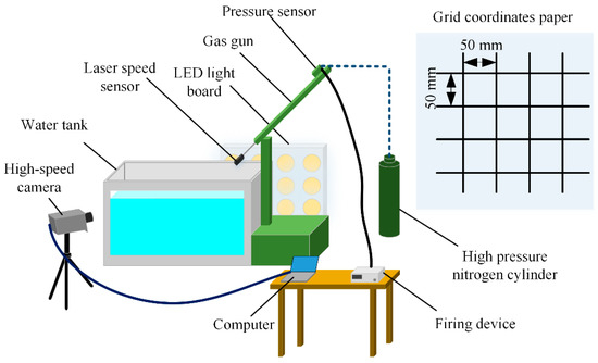
Figure 1.
Schematic diagram of the experimental equipment.

Figure 2.
Experimental equipment.
The horizontal size of the water tank is 3.0 m × 1.5 m × 1.5 m. The structure of the water tank is reinforced with a steel frame. Two pieces of toughened glass are installed on the side of the water tank to facilitate the observation of the water-entry process. The depth of water injection is 1.2 m. A projectile-receiving buffer device is arranged at the bottom of the water tank, and the projectile-receiving buffer device consists of a thickness of 25 mm pine and a thickness of 6 mm steel plate.
The launch system comprises a gas gun, an angle adjuster, a firing device, a gas storage container and a high-pressure gas cylinder. The gas gun is made of a steel tube with an inner diameter of 8 mm and a length of about 1.5 m. The angle adjuster is driven by a hydraulic device and can adjust any different water-entry angle within 0~90°.
The projectile was originally fixed in the gas gun tube and then accelerated by triggering the firing mechanism, which allows highly compressed nitrogen in the small gas storage container to be transported into the gun tube. The initial launch pressure is obtained by a pressure sensor mounted on a small gas storage container. By varying the initial launch pressure, different entry speeds are obtained. The initial velocity of the projectile can be obtained by a laser velocity sensor mounted at the mouth of the gas gun.
The high-speed photography system contains a light board, a coordinate paper and a high-speed camera. In the water-entry experiment, a high-brightness light board composed of 60 LED lamps was used as the background light source and placed at the back glass of the water tank. In addition, a soft screen is arranged between the water tank and the light board to make the background light uniform. At the same time, a piece of white coordinate paper (grid size is 50 mm × 50 mm) is pasted on the back glass of the water tank, which is convenient to extract the motion information of the projectile accurately. A high-speed camera (Photron FASTCAM SA-X2) was arranged at the front glass of the water tank to record the water-entry process. The frame rate and resolution of the camera were set to 7200 fps and 1024 (H) × 1024 (V) pixels, respectively.
The experimental projectile model is a cone-nosed revolution body, as illustrated in Figure 3. The main structure parameters of the projectile are listed in Table 1. The material employed for the projectile is 45# annealed steel.
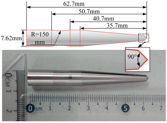
Figure 3.
Experimental projectile model.

Table 1.
Main structure parameters of the projectile.
2.2. Method for Processing Experimental Results
In this study, the digital image processing method is applied to detect the cavity contour, the edge of the cylinder and the attitude of the cylinder according to a grayscale image (Gonzalez et al. [35]). This method has been adopted by many scholars and its accuracy has been verified (Truscott et al. [36]; Truscott et al. [37]; Wei et al. [38]; Xia et al. [39]). The projectile position, trajectory and cavity profile information are extracted according to the different gray values of the photos. The projectile displacement is obtained by getting the projectile position in two experimental images at different times. The speed of the projectile is achieved by deriving its displacement. The velocity and acceleration of the projectile can be obtained by the first derivative and the second derivative of the displacement. The measurement error is reduced by fetching the pixel information of multiple experimental images.
In addition, before using the digital image processing method to convert the original experimental image into a grayscale image, it is necessary to preprocess the original experimental image to make the extraction of experimental data easier and the experimental images clearer. The specific approach is to enhance the brightness of the original experimental images and eliminate the background noise according to the bilateral filter method which is defined in Equation (1):
where is the new value of the central pixel, is the neighboring pixel value of the central, is the weight of , and W is the sum of all weights.
As shown in Figure 4a, there are a lot of black shadow areas and noises that will affect the extraction of experimental data. According to the image preprocessing method which was mentioned above, the shadow area and noise were eliminated, but the splash, cavity contours and coordinate paper remained and became clearer.
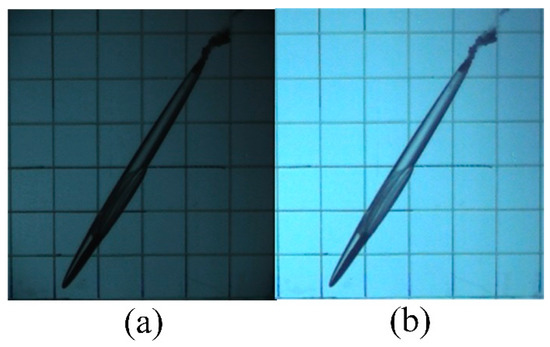
Figure 4.
Images without and with image processing: (a) original experimental image; (b) preprocessed image.
Due to the influence of the refraction effect on the experimental images captured by the high-speed camera, a correction algorithm is adopted to correct the experimental data in this study (Lu et al. [40]; Xia et al. [39]) and defined in Equation (2):
where = 0.75 m is the distance from the lens of the high-speed camera to the front wall of the water tank, = 1.5 m is the distance from the cylinder axis to the front wall of the water tank, is the measured value of the depth of cylinder, is the real value of the depth of cylinder, and = 1.333 is the refractive index.
2.3. Repeatability Test
A repeatability test is conducted for three different initial speeds of the projectile (v0 = 105 m/s, 130 m/s and 155 m/s). Figure 5 shows a series of images of cavity shapes in the repeatability test. The time t = 0 ms is defined as the moment that the cylinder head touches the air-water interface.
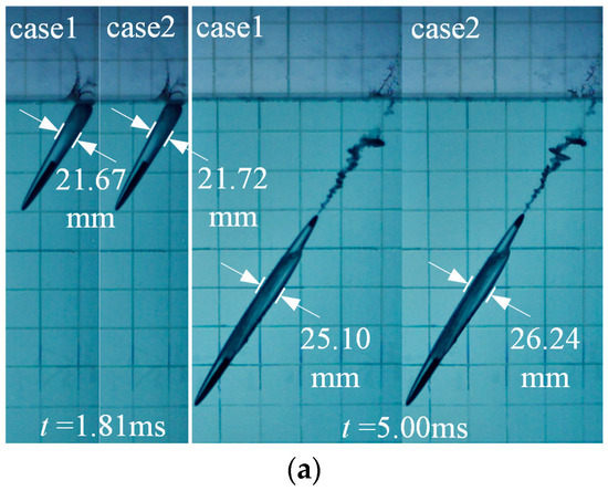
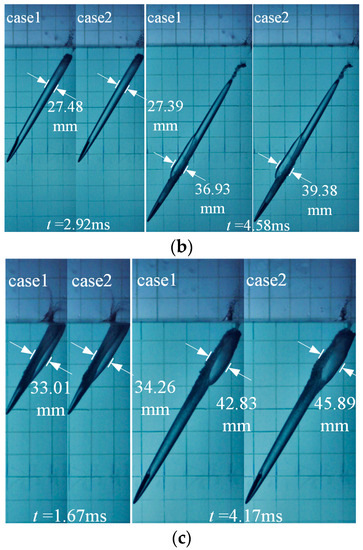
Figure 5.
Images of cavity shapes during water-entry in two cases for three different initial speeds: (a) v0 = 105 m/s, (b) v0 = 130 m/s, (c) v0 = 155 m/s.
As can be seen from Figure 5, for three different initial speeds, the splashes, cavity shapes, cylinder attitudes and the occurrence time and direction of tail-slapping motion show good consistency in two cases, and the maximum errors of the cavity size under the three different initial velocities are 4.54%, 6.63% and 7.14%, respectively. The experimental repeatability in this study is verified.
3. Results and Discussion
3.1. Influence of the Tail-Slapping Motion on the Evolution of the Cavity
Figure 6 shows the cavity evolution during the projectile entering the water at an initial speed of 130 m/s. As can be seen from Figure 6, at the moment of entering the water, the head of the projectile impacts the air-water interface. Part of the kinetic energy of the projectile is transferred to the water area near the head of the projectile to form an obvious splash. Once the projectile fully submerges into the water, it creates a smooth and transparent cavity where only the head of the projectile contact with the water, while the rest of its body is totally encapsulated. The trajectory of the projectile remains relatively stable. However, under the influence of the water-entry impact, the projectile gradually deflects counterclockwise in the cavity and touches the upper wall of the cavity at t = 2.92 ms. As the increase in the deflection amplitude, the projectile tail penetrates the cavity wall and a new cavity is generated in the water. For the convenience of the following analysis, the newly generated cavity is defined as the cavity, and the cavity that encapsulates the projectile body is called the original cavity. As shown in Figure 6, the cavity and the original cavity fit closely in position, but they are mutually independent in contour profile.
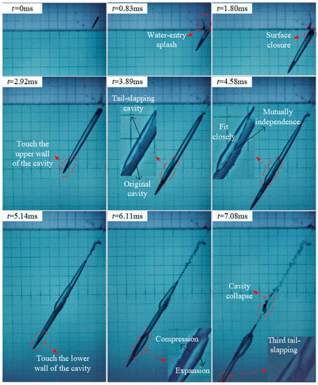
Figure 6.
Cavity evolution of the projectile at an initial speed of 130 m/s.
The schematic diagram of forces on the wetted surface of the projectile tail after the tail-slapping motion occurrence is presented in Figure 7. It can be seen that the forces mainly include the pressure along the normal direction of the tail wall surface after the tail is wetted, F1, and the axial fluid drag that hinders the downward movement of the tail, F2. The above two forces together induce the generation of the rotational torque of the projectile tail at the centroid of the projectile after the occurrence of the wetting phenomenon.
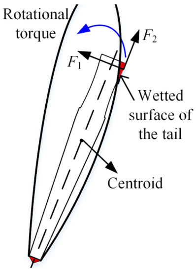
Figure 7.
Schematic diagram of forces on the wetted projectile tail.
As a result of this rotational torque, the projectile veers towards the opposite side of the cavity during each tail-slapping motion, before the subsequent tail-slapping motion becomes visible.
Due to the existence of this rotational torque, the projectile veers towards the opposite side of the cavity at the end of each tail-slapping motion, and then the next tail-slapping motion comes out into view. As shown in Figure 6, under the action of the rotational torque, the projectile turns back to the original cavity at t = 3.89 ms, and the tail-slapping cavity is no longer elongated. But then the projectile deflects to the opposite side of the original cavity and hits the lower wall of the cavity at t = 5.14 ms. The second tail-slapping motion appears. During this period, the tail-slapping cavity continues to expand outwards on the one hand, and on the other hand, it compresses the original cavity inwards. Finally, the tail-slapping cavity is pulled off from the surface of the original cavity and collapses in a bean shape, while the original cavity continues to move downward with the projectile after completing the surface closure at t = 1.80 ms. In addition, it can be found that the third tail-slapping motion occurs when the projectile deflects in the counterclockwise direction at t = 7.08 ms.
In order to obtain the regular change of the time interval of the tail-slapping motion, a dimensionless quantity t* = Δtv0/L is defined. Δt is the time interval between two tail-slapping motions, v0 is the initial entry speed of the projectile, and L is the length of the projectile. According to Fig4., it can be found that from the entry of the tail of the projectile (t = 0.42 ms) to the appearance of the first tail-slapping motion (t = 2.92 ms), t* = 5.58. From the end of the first tail-slapping motion (t = 3.89 ms) to the appearance of the second tail-slapping motion (t = 5.14 ms), t* = 2.79. From the end of the second tail-slapping motion to the start of the third slapping, t* = 2.17. It can be concluded that with the increase in the number of tail-slapping motions, the time interval between two tail-slapping motions is gradually shortened.
Figure 8 and Figure 9 illustrate the local evolution details of the cavity near the projectile when the first and second tail-slapping motions occur. It can be found from Figure 8a and Figure 9a that during the early stage of the two tail-slapping motions, the projectile tail strikes the cavity wall, which causes slight deformation and bulge of the original cavity. This is primarily due to that the deflection amplitude of the projectile is minimal during the initial phase of the tail-slapping motion, and the projectile has not yet penetrated the cavity wall and entered the water. The clarity and transparency of the original cavity also prove that the integrity of the original cavity is still good. However, with the increase in deflection amplitude, the projectile tail of the two tail-slapping motions pierces the original cavity into the water at t = 3.20 ms and t = 5.42 ms, respectively. At the same time, a jet flow is generated and shoots into the cavity from the wetted part of the tail, which makes the original cavity no longer transparent. When the projectile swings back to the original cavity, the two tail-slapping motions end at t = 3.89 ms and t = 6.11 ms, respectively.
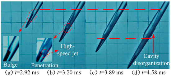
Figure 8.
Local evolution details of the cavity near the projectile of the first tail-slapping motion.

Figure 9.
Local evolution details of the cavity near the projectile of the second tail-slapping motion.
In addition, as we can see from Figure 8 and Figure 9, the tail-slapping cavity starts to form when the projectile’s tail makes contact with the inner wall of the original cavity and concludes when the projectile swings back to the inside of the original cavity. After each tail-slapping motion ends, the length and depth of the tail-slapping cavity is not changed significantly, while the wall of the tail-slapping cavity continues to expand outward along the radial direction for a certain distance. The reason is that after the end of the tail-slapping motion, the tail-slapping cavity loses the traction pointing to the direction of movement of the projectile because of its separation from the wetted surface of the projectile tail, so the length and depth of the tail-slapping cavity have almost no change.
However, the cavity wall continues to expand radially outward under the effect of inertia and finally stops under the action of the water pressure and the surface tension.
According to Figure 8d and Figure 9d, it can be found that unlike the tail-slapping cavity, which is clear, transparent and stable in structure, the original cavity of the same depth becomes turbid and collapses after the occurrence of the tail-slapping motion. The main reason for this phenomenon is that after the projectile penetrates into the original cavity, the high-speed jet will be produced in the original cavity and impact the side wall of the cavity, which will affect the stability of the original cavity structure and lead to the rapid collapse of the original cavity. Since the tail-slapping cavity closely fits with the original cavity and the jet flow does not break through the connected wall of the two cavities, the tail-slapping cavity structure is relatively stable due to the small impact. In addition, the original cavity after the occurrence of the second tail-slapping motion is more turbid and the collapse phenomenon is more prominent than those after the occurrence of the first tail-slapping motion, which indicates that the jet flow in the original cavity that is produced after the occurrence of the second tail-slapping motion has higher speed and impact energy.
Figure 10 and Figure 11 show the details of the collapse of the tail-slapping cavity after the occurrence of the first and second tail-slapping motion. From the previous analysis, it can be seen that the depth of the tail-beating cavity will not change significantly after the end of the tail-beating motion, while the original cavity will continue to move downward with the projectile after the surface closure happens. As time goes by, the original cavity tail of the two tail-slapping motions moves to the upper end of the tail-slapping cavity at t = 6.25 ms and t = 8.19 ms, respectively. As local high-pressure zone 1 is around the area of the original cavity tail, and there is the low internal pressure of the tail-slapping cavity, under the action of the pressure gradient inside and outside the cavity, high-speed jet-flow 1 emerges from the tail of the original cavity and shoots to the tail-slapping cavity. Ulteriorly, jet flow 1 diffuses and impacts the wall of the cavity, which aggravates the instability of the cavity. The tail-slapping cavity begins to collapse from the tail, and the cavity length gradually shortens. In addition, in the process of the two tail-slapping motions, the tail-slapping cavity is pulled off from the surface of the original cavity at t = 7.08 ms and t = 9.17 ms, respectively. At the same time, the original cavity completes deep closure, and local high-pressure zone 2 is formed at the closure point, which causes high-speed jet flow 2 inside the tail-slapping cavity. As shown in Figure 11d, jet flow 2 diffuses upward inside the tail-slapping cavity and finally accelerates the collapse of the tail-slapping cavity. In addition, it can also be seen from Figure 8 and Figure 11 that the original cavity structure of the same depth has been destroyed and completely collapsed when the tail-slapping motion starts to collapse. To sum up, although the behavior of the tail-slapping motion is able to make the projectile recover its stability after deflection, the jet flow and the impact generated during the tail-slapping motion process can quickly destroy the integrity of the cavity structure, and collapse the cavity, which has a great adverse effect on the stability of the projectile cavity.
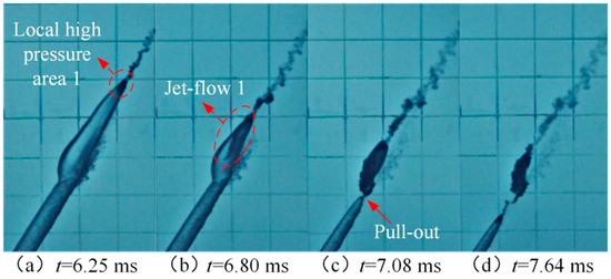
Figure 10.
Details of the collapse of the first tail-slapping cavity.
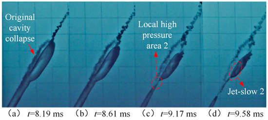
Figure 11.
Details of the collapse of the second tail-slapping cavity.
3.2. Influence of Initial Entry Speed on the Tail-Slapping Motion
The motion coordinate is defined as shown in Figure 12. The entry angle β is the angle between the projectile speed axis and the air-water interface. The projectile speed is represented by v, and v0 depicts the initial entry speed of the projectile. The contact point between the projectile head and the air-water interface is the origin of the coordinate system, denoted by O. The X-axis coincides with the air-water interface, and the angle between the Y-axis and the X-axis is 90° and the Y-axis is positive downward.
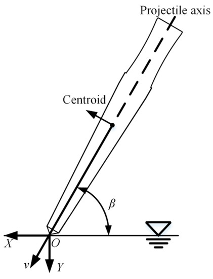
Figure 12.
Projectile motion coordinate system.
Figure 13 shows the cavity evolutions during the water-entry process of the projectile with β = 55° at v0 = 105 m/s, 130 m/s and 155 m/s. By comparing Figure 13a–c, it can be found that although the tail-slapping phenomenon occurs after the projectile enters the water under different working conditions, the characteristics of the cavity evolution are obviously different with the increase in initial speed. By comparing three different entry speeds, the projectile deflects after entering the water, and the tail-slapping phenomenon comes into sight at t = 3.33 ms, t = 2.92 ms and t = 1.67 ms, respectively. In addition, with the increase in the initial speed, the first tail-slapping motion takes place earlier. Moreover, it can also be observed from Figure 13 that for the first tail-slapping motion of three different entry speeds, the tail-slapping cavity reaches the maximum size at t = 5.00 ms, t = 4.58 ms and t = 3.33 ms, respectively. As v0 increases, the maximum size of the tail-slapping cavity enlarges. This is due to the higher entry speed, the residual kinetic energy of the projectile is larger when the first tail-slapping motion happens, and more energy is transferred to the tail-slapping cavity to expand. In addition, for three entry speeds of v0 = 105 m/s, 130 m/s and 155 m/s, the surface closure of the original cavity occurs at t = 3.33 ms, t = 3.89 ms and t = 4.17 ms, respectively, and the maximum length of the original cavity appears at t = 5.97 ms, t = 6.11 ms and t = 4.86 ms, which is 4 L, 7.6 L and 8.5 L. It means that with the increase in v0, it needs more time to finish the surface closure and forms a longer cavity.
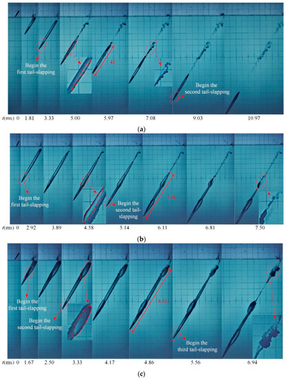
Figure 13.
Evolutions of the cavity of the water-entry process of the projectile under three different entry speeds: (a) v0 = 105 m/s; (b) v0 = 130 m/s; (c) v0 = 155 m/s.
It can also be found from Figure 13 that for v0 = 105 m/s, 130 m/s and 155 m/s, the tail-slapping cavity completely collapses at t = 7.08 ms, t = 7.50 ms and t = 6.84 ms, respectively. In addition, with the increase in the initial entry speed, the volume of the air-vapor-water mixture formed after the collapse gradually rises, which is related to the formation of a larger volume and higher energy tail-slapping cavity when the projectile enters the water with a higher initial velocity. Furthermore, the gas-liquid mixture formed by the collapse is asymmetrically distributed along the axis of the projectile; specifically, there are more mixtures on the side of the tail-slapping cavity, while there are fewer mixtures on the side of the original cavity.
Figure 14 shows the variation curves of the dimensionless speed and acceleration of the projectile at three different oblique initial entry speeds. The dimensionless speed and acceleration δ = v/v0 and μ = a/g are defined, where v and a are the axial speed and acceleration of the projectile at the current monitoring point. g is the gravitational acceleration. By observing the dimensionless acceleration curves, it can be found that the acceleration of the projectile during the early stage of entering water under three entry speeds has a maximum value, and then it decreases rapidly with the formation of the water-entry cavity. As the projectile continues to move under the water, the dimensionless acceleration in Figure 14 fluctuates. This is due to the impact of the water-entry disturbance, the projectile will have a tail-slapping motion after the projectile enters the water at different entry speeds. After the tail-slapping motion starts, a portion of the projectile tail gets wet and is subject to fluid drag. With the increase in the wetted area of the projectile tail, the fluid drag on the projectile increases, and the acceleration of the projectile also increases. Then the projectile deflects reversely under the effect of the rotational torque. During this period, the acceleration of the projectile gradually declines with the decrease in the wetted area of the projectile tail. After the projectile completely turns back to the original cavity, the projectile tail is free from the influence of the fluid drag, and the acceleration of the projectile also reaches the valley value. The dimensionless acceleration is going to fluctuate again after the next tail-slapping motion occurs. It can also be found from Figure 14b that the peak value of the dimensionless acceleration of the projectile in the process of the second tail-slapping motion is greater than that of the first tail-slapping motion, which indicates that the peak value of the rotational force on the projectile during the second-slapping is higher, thus forming a greater rotational torque. At the same time, compared with the first tail-slapping motion, the kinetic energy of the projectile is relatively small in the process of the second tail-slapping motion as the projectile moves downward, resulting in the smaller size of the cavity near the projectile tail. Under the combined action of the increase in the rotational torque and the decrease in the size of the projectile tail cavity, the frequency of the tail-slapping motion of the projectile gradually increases, which is consistent with the mentioned phenomenon that the time interval between two tail-slapping motions gradually decreases with the increase in the number of tail-slapping motions.
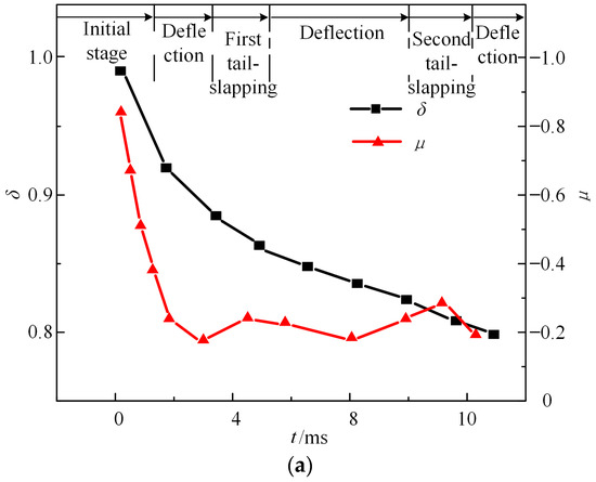
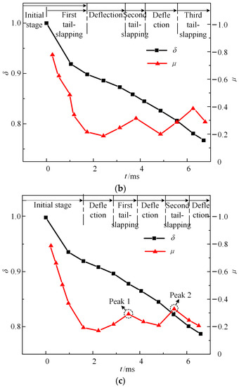
Figure 14.
Dimensionless velocities and accelerations under three different entry speeds: (a) v0 = 105 m/s: (b) v0 = 130 m/s; (c) v0 = 155 m/s.
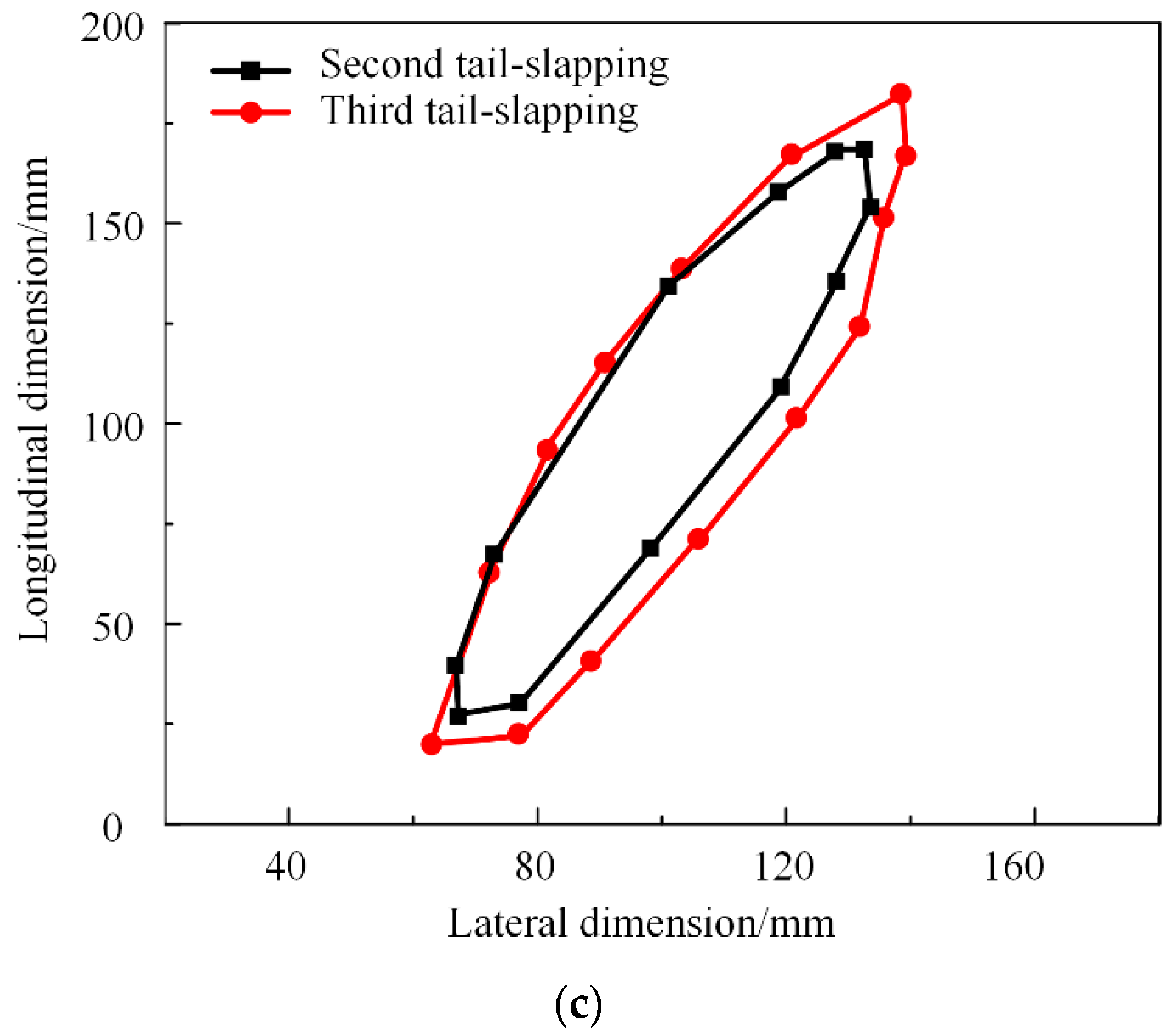
By comparing Figure 14a–c, it can be found that with the increase in the initial entry speed of the projectile, the peak value of the dimensionless acceleration in the process of the tail-slapping motion also gradually increases. It can be seen from the previous analysis that, unlike v0 = 105 m/s, the deflection amplitude of the projectile is relatively small. With the increase in the initial entry speed, for v0 = 130 m/s and 155 m/s, the deflection amplitude of the projectile gradually enlarges in the process of the tail-slapping motion, and the maximum wetted area of the projectile tail also increases, which makes the peak value of the dimensionless acceleration in the process of the tail-slapping motion shows an increasing trend. According to the analysis of the projectile speed variation in Figure 14, for v0 = 105 m/s, as shown in Figure 14a, the speed of the projectile attenuates by 2.88% in the process of the first tail-slapping motion, and 3.03% in the process of the second tail-slapping motion; for v0 = 130 m/s, as shown in Figure 14b, the speed of the projectile decreases by 3.06% in the process of the first tail-slapping motion, and 3.76% in the process of the second tail-slapping motion; and for v0 = 155 m/s, as shown in Figure 14c, since the first tail-slapping motion of this working condition occurs in the early stage of water-entry, the impact load of water-entry in this period has a dominant influence on the speed attenuation of the projectile, which leads to a sharp drop in speed, while the tail-slapping motion is not the decisive factor for the speed attenuation of the projectile in this period, so the second and third tail-slapping motion without the impact influence are selected for analysis in this study. The speed of the projectile for v0 = 155 m/s decreases by 2.40% in the process of the second tail-slapping motion, and 5.52% in the process of the third tail-slapping motion. From the above analysis, it can be found that compared with the previous tail-slapping motion, the attenuation of the projectile speed in the next tail-slapping motion is greater. In addition, it can be analyzed in combination with Figure 15, which shows the comparison of the maximum cross-section size profile of the tail-slapping cavity generated by two tail-slapping motions under three different entry speeds. As we can see from Figure 15a–c, compared with the first tail-slapping motion, the axial size of the tail-slapping cavity produced by the second tail-slapping motion has little change, while the radial size is larger. The cavity cross-section areas for three different entry speeds increased by 10.69%, 91.17% and 40.39%, respectively. It can be inferred that the projectile will use more energy for the cavity expansion and then transfer to the water in the process of the second tail-slapping motion. Therefore, with the increase in the number of tail-slapping motions, the speed of the projectile decays faster during each tail-slapping motion, resulting in higher energy loss and a decrease in the speed storage capacity of the projectile.
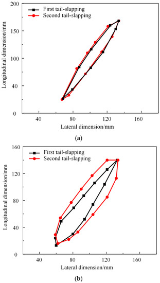
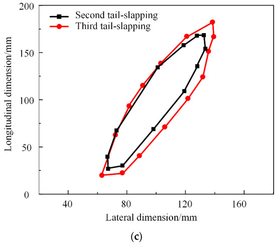
Figure 15.
Comparison of the maximum cross-section size of the tail-slapping cavity generated by two tail-slapping motions under three different entry speeds: (a) v0 = 105 m/s; (b) v0 = 130 m/s; (c) v0 = 155 m/s.
4. Conclusions
In this study, we conducted experimental investigations on the tail-slapping motion of the projectile during oblique water entry using high-speed photography technology. We explored the formation mechanism of the tail-slapping motion and examined its influence on the evolution of the projectile cavity. Additionally, we analyzed the evolution characteristics of the tail-slapping cavity and the original cavity under different initial water-entry speeds. Furthermore, we discussed the impact of the tail-slapping motion on the water-entry motion characteristics of the projectile. The main conclusions can be summarized as follows:
(1) The tail-slapping motion clearly affects the water-entry projectile cavity evolution characteristics. During the water-entry process, the projectile tail repeatedly hits the original cavity wall, causing the projectile to swing back and forth inside the original cavity. A clear and transparent tail-slapping cavity is formed in the process of the reciprocating motion of the projectile. The tail-slapping cavity is closely connected with the original cavity and finally pulled off from the surface of the original cavity to collapse. The high-speed jet flow generated by the tail-slapping motion causes the original cavity to collapse prematurely.
(2) As the initial water-entry speed increases, both the maximum cross-section size of the tail-slapping cavity and the length of the original cavity gradually increase. In addition, the degree of the cavity collapse becomes more intense at higher initial water-entry speeds. This results in a larger volume of gas-liquid mixture being present in the water after the cavity collapse.
(3) With the increase in the initial water-entry speeds, the deflection amplitude gradually increases during the tail-slapping, leading to an increase in the wetting area of the projectile. As the number of tail-slapping motions increases, the speed attenuation amplitude of the projectile increases in the process of each tail-slapping motion, and the time interval between two tail-slapping motions is gradually shortened, causing an increase in energy loss and a decrease in the speed storage capacity of the projectile.
Author Contributions
Conceptualization, L.L., X.Y., Q.L. and Y.H.; methodology, L.L. and C.G.; investigation, C.G. and D.Z.; data curation, C.G., F.L., X.Y. and Y.H.; writing—review and editing, L.L. and Q.L.; editing, F.L., D.Z. and Y.H.; funding acquisition, L.L. All authors have read and agreed to the published version of the manuscript.
Funding
This research was funded by the National Natural Science Foundation of China, grant number 52201385, the Natural Science Foundation of Shanxi Province, grant number 20210302123023, and the Shanxi Scholarship Council of China, grant number 2020-106.
Institutional Review Board Statement
Not applicable.
Informed Consent Statement
Not applicable.
Data Availability Statement
The data that support the findings of this study are available from the corresponding author upon reasonable request.
Conflicts of Interest
The authors declare no conflict of interest.
References
- Lee, M.; Longoria, R.G.; Wilson, D.E. Cavity dynamics in high-speed water entry. Phys. Fluids 1997, 9, 540–550. [Google Scholar] [CrossRef]
- Lee, M.; Longoria, R.G.; Wilson, D.E. Ballistic waves in high-speed water entry. J. Fluid. Struct. 1997, 11, 819–844. [Google Scholar] [CrossRef]
- Savchenko, Y.N. Perspectives of the supercavitation flow applications. In International Conference on Innovative Approaches to Further Increase Speed of Fast Marine Vehicles, Moving above, under and in Water Surface; SuperFAST: Saint-Petersburg, Russia, 2008. [Google Scholar]
- Cameron, P.J.K.; Rogers, P.H.; Doane, J.W.; Gifford, D.H. An Experiment for the Study of Free-Flying Supercavitating Projectiles. J. Fluids Eng. 2011, 133, 021303. [Google Scholar] [CrossRef]
- Erfanian, M.R.; Anbarsooz, M.; Rahimi, N. Numerical and experimental investigation of a three dimensional spheri-cal-nose projectile water entry problem. Ocean Eng. 2015, 104, 397–404. [Google Scholar] [CrossRef]
- Forouzani, H.; Saranjam, B.; Kamali, R. A study on the motion of high speed supercavitating projectiles. J. Appl. Fluid. Mech. 2018, 11, 1727–1738. [Google Scholar] [CrossRef]
- Jiang, Y.; Jeong, S.; Ahn, B.; Kim, H.; Jung, Y. Experimental investigation of drag characteristics of ventilated supercav-itating vehicles with different body shapes. Phys. Fluids 2019, 31, 052106. [Google Scholar] [CrossRef]
- Hong, Y.; Wang, B.; Liu, H. Numerical study of hydrodynamic loads at early stage of vertical high-speed water entry of an axisymmetric blunt body. Phys. Fluids 2019, 31, 102105. [Google Scholar] [CrossRef]
- Chen, T.; Huang, W.; Zhang, W.; Qi, Y.; Guo, Z. Experimental investigation on trajectory stability of high-speed water entry projectiles. Ocean Eng. 2019, 175, 16–24. [Google Scholar] [CrossRef]
- Li, D.; Zhang, J.; Zhang, M.; Huang, B.; Ma, X.; Wang, G. Experimental study on water entry of spheres with different surface wettability. Ocean Eng. 2019, 187, 106123. [Google Scholar] [CrossRef]
- Li, Q.; Lu, L. Numerical Investigations of Cavitation Nose Structure of a High-Speed Projectile Impact on Water-Entry Characteristics. J. Mar. Sci. Eng. 2020, 8, 265. [Google Scholar] [CrossRef]
- Liu, H.; Zhou, B.; Han, X.; Zhang, T.; Zhou, B.; Gho, W.M. Numerical simulation of water entry of an inclined cylinder. Ocean Eng. 2020, 215, 107908. [Google Scholar] [CrossRef]
- Yun, H.; Lyu, X.; Wei, Z. Experimental study on vertical water entry of two tandem spheres. Ocean Eng. 2020, 201, 107143. [Google Scholar] [CrossRef]
- Sun, T.; Zhou, L.; Yin, Z.; Zong, Z. Cavitation bubble dynamics and structural loads of high-speed water entry of a cylinder using fluid-structure interaction method. Appl. Ocean Res. 2020, 101, 102285. [Google Scholar] [CrossRef]
- Sun, T.; Wang, H.; Shi, C.; Zong, Z.; Zhang, G. Experimental study of the effects of a viscous liquid layer on the cavity dynamics of vertical entry by a sphere into water at low Froude number. Phys. Fluids 2021, 33, 013308. [Google Scholar] [CrossRef]
- Yu, Y.; Shi, Y.; Pan, G.; Chen, X.; Zhao, H.; Gao, S. Effect of asymmetric nose shape on the cavity and mechanics of projectile during high-speed water entry. Ocean Eng. 2022, 266, 112983. [Google Scholar] [CrossRef]
- Gao, J.-G.; Chen, Z.-H.; Huang, Z.-G.; Wu, W.-T.; Xiao, Y.-J. Numerical investigations on the oblique water entry of high-speed projectiles. Appl. Math. Comput. 2019, 362, 124547. [Google Scholar] [CrossRef]
- Song, Z.; Duan, W.; Xu, G.; Zhao, B. Experimental and numerical study of the water entry of projectiles at high oblique entry speed. Ocean Eng. 2020, 211, 107574. [Google Scholar] [CrossRef]
- Sui, Y.-T.; Zhang, A.-M.; Ming, F.-R.; Li, S. Experimental investigation of oblique water entry of high-speed truncated cone projectiles: Cavity dynamics and impact load. J. Fluids Struct. 2021, 104, 103305. [Google Scholar] [CrossRef]
- Hong, Y.; Zhao, Z.; Gong, Z.; Liu, H. Cavity dynamics in the oblique water entry of a cylinder at constant velocity. Phys. Fluids 2022, 34, 021703. [Google Scholar] [CrossRef]
- Hou, Y.; Huang, Z.; Chen, Z.; Guo, Z.; Xu, Y. Experimental investigations on the oblique water entry of hollow cylinders. Ocean Eng. 2022, 266, 112800. [Google Scholar] [CrossRef]
- Liu, H.; Zhou, B.; Yu, J.; Liu, K.; Han, X.; Zhang, G. Experimental investigation on the multiphase flow characteristics of oblique water entry of the hollow cylinders. Ocean Eng. 2023, 272, 113902. [Google Scholar] [CrossRef]
- Zhao, Z.-X.; Hong, Y.; Gong, Z.-X.; Liu, H. Numerical analysis of cavity deformation of oblique water entry using a multi-resolution two-phase SPH method. Ocean Eng. 2023, 269, 113456. [Google Scholar] [CrossRef]
- Lu, L.; Wang, C.; Li, Q.; Sahoo, P.K. Numerical investigation of water-entry characteristics of high-speed parallel pro-jectiles. Int. J. Nav. Archit. Ocean Eng. 2021, 13, 450–465. [Google Scholar] [CrossRef]
- Lu, L.; Yan, X.; Li, Q.; Wang, C.; Shen, K. Numerical study on the water-entry of asynchronous parallel projectiles at a high vertical entry speed. Ocean Eng. 2022, 250, 111026. [Google Scholar] [CrossRef]
- Lu, L.; Gao, C.; Qi, X.; Zhang, D.; Li, Q.; Yan, X.; Hu, Y. Numerical study on the water-entry characteristics of asyn-chronous parallel projectiles at an oblique impact angle. Ocean Eng. 2023, 271, 113697. [Google Scholar] [CrossRef]
- Zou, W.; Liu, H. Modeling and Simulations of the Supercavitating Vehicle With Its Tail-Slaps. J. Fluids Eng. 2015, 137, 041302. [Google Scholar] [CrossRef]
- Zhao, C.; Wang, C.; Wei, Y.; Zhang, X.; Sun, T. Experimental study on oblique water entry of projectiles. Mod. Phys. Lett. B 2016, 30, 1650348. [Google Scholar] [CrossRef]
- Zhao, X.; Lyu, X.; Li, D. Modeling of the Tail Slap for an Underwater Projectile within Supercavitation. Math. Probl. Eng. 2019, 2019, 1290157. [Google Scholar] [CrossRef]
- Akbari, M.A.; Mohammadi, J.; Fereidooni, J. Stability of Oblique Water Entry of Cylindrical Projectiles. J. Appl. Fluid. Mech. 2020, 14, 301–314. [Google Scholar]
- Akbari, M.A.; Mohammadi, J.; Fereidooni, J. A dynamic study of the high-speed oblique water entry of a stepped cy-lindrical-cone projectile. J. Braz. Soc. Mech. Sci. 2021, 43, 1–15. [Google Scholar]
- Gu, J.; Dang, J.; Huang, C.; Li, D.; Liu, F. Influence of Weight Parameters on the Effective Range of Supercavitation Projectile. Acta Armamentarii. 2022, 43, 1376. (In Chinese) [Google Scholar]
- Sui, Y.T.; Li, S.; Ming, F.R.; Zhang, A.M. An experimental study of the water entry trajectories of truncated cone pro-jectiles: The influence of nose parameters. Phys. Fluids. 2022, 34, 052102. [Google Scholar] [CrossRef]
- Huang, C.; Liu, Z.; Liu, Z.; Hao, C.; Li, D.; Luo, K. Motion characteristics of high-speed supercavitating projectiles in-cluding structural deformation. Energies 2022, 15, 1933. [Google Scholar] [CrossRef]
- Gonzalez, R.C.; Woods, R.E.; Eddins, S.L. Digital Image Processing Using MATLAB; McGraw Hill Education: New York, NY, USA, 2013. [Google Scholar]
- Truscott, T.T.; Techet, A.H. Water entry of spinning spheres. J. Fluid. Mech. 2009, 625, 135–165. [Google Scholar] [CrossRef]
- Truscott, T.T.; Epps, B.P.; Techet, A.H. Unsteady forces on spheres during free-surface water entry. J. Fluid. Mech. 2012, 704, 173–210. [Google Scholar] [CrossRef]
- Wei, Z.; Hu, C. Experimental study on water entry of circular cylinders with inclined angles. J. Mar. Sci. Technol. 2015, 20, 722–738. [Google Scholar] [CrossRef]
- Xia, W.; Wang, C.; Wei, Y.; Li, J.; Li, Y.; Yang, L. Position detection method and hydrodynamic characteristics of the water entry of a cylinder with multidegree motion. Exp. Fluids 2020, 61, 57. [Google Scholar] [CrossRef]
- Zhonglei, L.; Tiezhi, S.; Yingjie, W.; Cong, W. Experimental investigation on the motion feature of inclined water-entry of a semi-closed cylinder. J. Theor. Appl. Mech. 2018, 50, 263–273. [Google Scholar]


Disclaimer/Publisher’s Note: The statements, opinions and data contained in all publications are solely those of the individual author(s) and contributor(s) and not of MDPI and/or the editor(s). MDPI and/or the editor(s) disclaim responsibility for any injury to people or property resulting from any ideas, methods, instructions or products referred to in the content. |
© 2023 by the authors. Licensee MDPI, Basel, Switzerland. This article is an open access article distributed under the terms and conditions of the Creative Commons Attribution (CC BY) license (https://creativecommons.org/licenses/by/4.0/).