Article

Experimental and Numerical Analysis of Ultimate Carrying Capacity of a Funnel Structure with Opening under Wind Pressure

1
Green & Smart River-Sea-Going Ship, Cruise and Yacht Research Center, Wuhan University of Technology, Wuhan 430063, China
2
Hubei Province Engineering Research Center on Green & Smart River-Sea-Going Ship, Wuhan 430063, China
3
School of Naval Architecture, Ocean and Energy Power Engineering, Wuhan University of Technology, Wuhan 430063, China
4
School of Foreign Studies, Jiangnan University, Wuxi 214122, China
*
Authors to whom correspondence should be addressed.
J. Mar. Sci. Eng. 2024, 12(1), 41; https://doi.org/10.3390/jmse12010041
Submission received: 3 December 2023 / Revised: 20 December 2023 / Accepted: 21 December 2023 / Published: 23 December 2023
(This article belongs to the Special Issue Advanced Analysis of Marine Structures—Edition II)

Abstract

:
This study presents experimental and finite element investigations on the ultimate strength of the funnel structure of a large passenger ship subjected to wind pressure. An experimental test is conducted using a similar model to analyze the failure characteristics of the funnel structure. The model is designed based on similar theories to simulate the progressive collapse behavior of an actual ship’s funnel under wind load. Additionally, a simplified wind loading device is also developed to apply large wind loads. Practical insights are provided in the research to assess the opening’s influence on reducing the ultimate strength of funnel structures when suffering wind pressure. Results represent the failure initiated at the edges of the large opening, with stress concentration primarily occurring at the stiffener end, showing good agreement with the simulated results performed using the finite element method. Furthermore, the effects of different parameters on the ultimate strength of the funnel structure are discussed by using the numerical method. This analysis provides an important guide for the design of funnel structures of passenger ships with openings.

1. Introduction

During the extended operational period, ships and offshore structures face constant threats from harsh ocean environments, such as strong winds, high waves, and extreme events like typhoons. These environmental factors may lead to fatigue, damage, or even collapse of the structures. Under extreme load scenarios like typhoons, more severe marine climatic conditions can result in significant structural vibrations and displacements [1,2]. This poses potential safety risks to the overall integrity of towering structures such as funnels and wind turbines [3]. It has been reported that all the wind turbines operated by Okinawa Electric Power Company were extensively damaged by Typhoon Maemi [4].
Large passenger ships are very complex objects from the structural point of view [5]. They usually have full superstructures that provide a range of amenities, including the swimming pool, central hall and shopping malls. These facilities cater to the varied requirements of passengers for transportation and leisure activities throughout their time at sea. In terms of their principal dimensions, the total height of the superstructure is nearly the same as that of the ship hull, bringing new structural problems.
When a cruise ship navigates in open waters, it experiences more forceful wind pressures, leading to a notable reduction in its velocity and stability [6]. Wang et al. [7] investigated the load characteristic induced by the wind acting on the passenger ship’s superstructure. They found that the extreme wind pressure could cause a large bending moment.
Furthermore, different openings are widely applied in the structural design of large passenger ships in order to accommodate specific layouts as well as minimize the overall weight of the ship. However, these openings can lead to structural issues such as local plate fracture, stress concentration and a significant reduction in the limit strength of ship structures. Several research studies have been conducted on the residual strength of passenger ship structures with various openings [8,9,10,11]. The collapse behaviour of panels under the action of both compression and lateral pressure have also been studied [12].
The nonlinear finite element method (NFEM) has been extensively employed in the numerical analysis of limit strength of ship structures because of the advantage of reducing cost, ease of implementation and provision of detailed information on the structural collapse mode. Morshedsolouk and Khedmati [13] evaluated the effectiveness of composite superstructures in contributing to the bending moment and observed that the superstructure’s dimension significantly influenced the hull’s failure mode. Romanoff et al. [14] conducted similar researches, noting a considerable increase in load distribution by the superstructure as the neutral axis moved close to the ship bottom.
Considering that the full-scale experiments are hard to implement and are of high cost, the scaled model tests have been developed to analyze ship structure failures. Ensuring a proper similarity law is crucial in these model tests [15], as it effectively guides the design of scaled models, enabling a suitable understanding of collapse behaviour and ultimate strength in real ships. To accurately reflect the nonlinear stage of progressive collapse in actual ships, it is important to analyze factors influencing nonlinear similarity during the testing. Benson et al. [16] conducted experimental studies on hull girders’s post-ultimate strength behaviour using three scaled girders. Hirdaris et al. [17] provided a comprehensive review on examining design loads for plate structures based on model tests as well as theoretical methods, with particular consideration given to environmental loads. Quispe et al. [18] performed a pure bending test on a scaled hull girder, which revealed the plates between stiffeners failed first. Pei et al. [19] enhanced the law for nonlinear similarity design and utilized it in a test model with a large opening subjected to combined longitudinal bending and torsion.
Numerous studies have been conducted to analyze the ultimate strength of local structures and hull girders through experimental methods. However, the failure experiment was not carried out on the ship funnel structures suffering the wind load. The present researches mainly focus on the wind load evaluation acting on the whole superstructure or the whole ship structure. In their study, Kulkarni et al. [20] conducted a comparison between numerical analysis and wind tunnel experiment in order to analyze the load coefficients of superstructures with various wind angles. Chen et al. [21] computed the wind loads acting on a cruise ship considering different load components. The findings indicate significant variations in the load coefficients depending on the incoming wind’s angles. Janssen et al. [22] carried out a computational analysis of wind forces acting on ships in order to explore how simplifying geometries affect load calculations. They computed wind forces for four simplified models ranging from rectangular girders to complex ship hulls. It was found that substantial reductions in complexity can result in notable discrepancies between calculated wind forces. In addition, most of the research objects corresponding to the wind load on funnel structures are funnel on land. Insufficient attention has been paid to investigating potential failures or accurately assessing the ultimate strength associated with the funnel design. Zhang [22] studied the failure process of an industrial funnel under different load conditions. Bhatt and Vasanwala [23] examined the ultimate strength of a funnel under monotonic load while considering the effects of various materials.
In this paper, the funnel structure with openings from a passenger ship is selected to analyze its collapse behaviour under wind load, experimentally and numerically. The research aims at determining the ultimate strength of the towering structure for improving the design and construction of the funnel in passenger ships. A scaled model is designed based on the nonlinear similar law. A new loading device is designed to simulate the wind pressure, and the feasibility of this method is demonstrated. The scaled model of the funnel is tested for failure and the buckling collapse behaviour is examined. The load–displacement curves and structural collapse patterns derived from the experiment are compared with the results through the nonlinear finite element calculation. The impact of the opening on reducing the ultimate strength of the funnel structure is assessed. The ultimate strength of the real ship funnel is finally predicted by using this similar law and the influences of various parameters on the funnel’s ultimate strength are analyzed for optimum structural design.

2. Scaled Experiment

2.1. Similarity Law

Given the high cost and operational challenges associated with conducting real ship tests, it is crucial to develop a scaled model that can accurately replicate the collapse mode of a full-scale structures for ultimate strength research. Thus, a suitable similarity law is needed to guarantee the corresponding relationship between the scaled prototype and the real structure. Firstly, geometric similarity is widely used to calculate the overall size of the scaled model [24]. The funnel works as a thin-walled cantilever beam under wind forces. Based on the beam theory, the geometric scaling law can be expressed as follows:
C A = A r / A s = C L C t C I = I r / I s = C L 3 C t Q s = Q r C L C t ,
where C represents the scaled ratio of the test model to the actual ship; A denotes the area of the segment; L denotes the length; t denotes the plate thickness; I represents the moment of inertia; Q refers to the ultimate wind force. Additionally, r and s, respectively, refer to the real ship and its corresponding model.
In addition to considering geometric and material similarity, it is important to make sure that the local strength is similar. The local plate strength of the scaled model may not accurately reflect the actual ship due to the limitations of linear geometry similarity design. Considering the nonlinear properties, the geometries of the local stiffened plates should be corrected based on their ultimate strength, respectively. The average ultimate stress of stiffened plates under uniaxial compression can be predicted by Equation (2) given by Zhang and Khan [25]:
σ u σ y = 1 β 0.28 1 1 + λ 3.2 β = b / t σ y / E λ = a / π A s / I s σ y / E .
σu is the ultimate strength; σy is the yield stress; β is the plate slenderness ratio; λ is the stiffener slenderness coefficient; b is the plate width between stiffeners; t is the plate thickness; E is the elastic modulus; a is the spacing between transverse frames; As and Is are the area and inertia moment of the stiffener with attached plate, respectively.
It is obvious that the ultimate strength of local stiffened plates is determined by parameters β and λ. Therefore, the nonlinear strength criterion for the local stiffened panel under compression is determined by
β p = β m λ p = λ m ,
p and m represent prototype and model, respectively.

2.2. Model Design

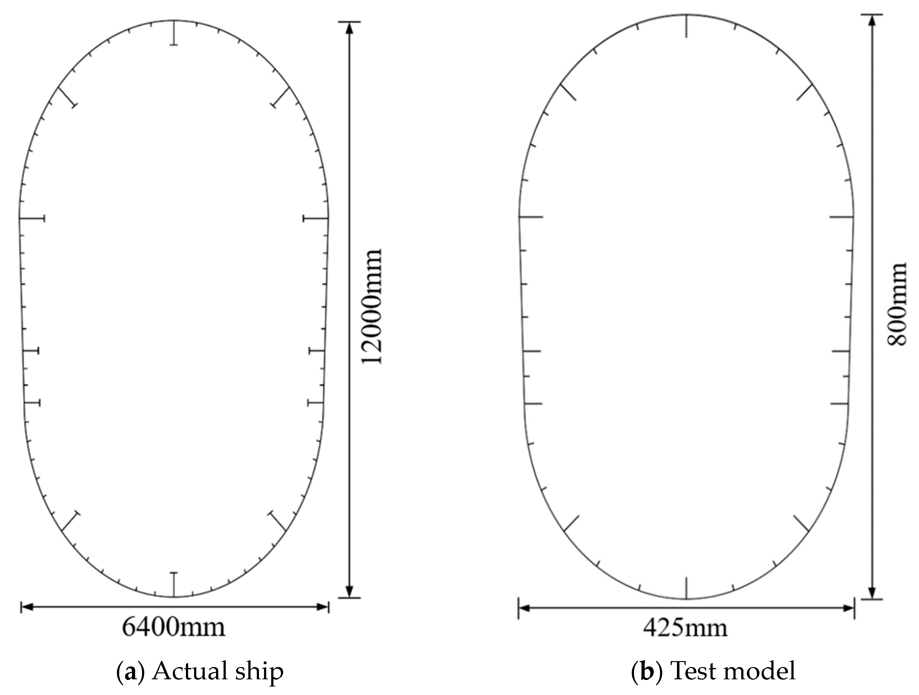
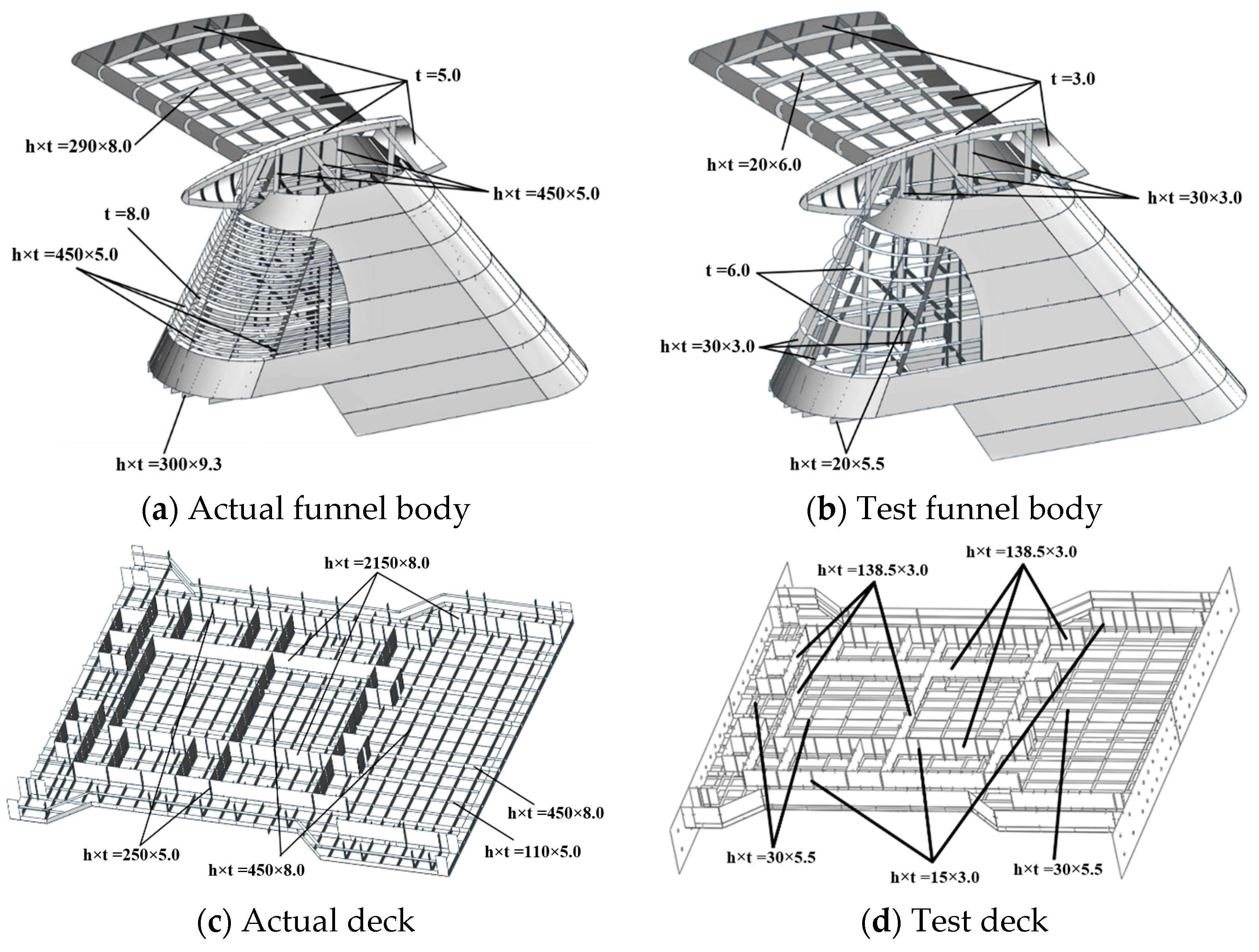
The actual funnel structure is shown in Figure 1. The max plate thickness of the actual funnel body is restricted to 5 mm for the purpose of weight control. The length ratio, denoted as CL, is established as 15:1, taking into account factors such as model costing, laboratory conditions, and fabrication process. Similarly, the thickness ratio, denoted as Ct, is taken as 5:3. Firstly, the initial dimensions of the scaled model are determined by geometric similarity. Then, the sizes of local stiffened plates are changed slightly to keep the same ultimate compressive strength. The details about the scaled model as well as the real structures are shown in Figure 2, Figure 3, Figure 4 and Figure 5.
Table 1 presents a comparison of geometric parameters for typical sections. The difference between the scaled model and the actual prototype is below 5%. Comparison of the plating slenderness ratio β and stiffener flexibility coefficient λ is shown in Table 2. The difference ratio is also within 5%. Thus, the designed model can reflect the elastic plastic characteristics of the actual structure.
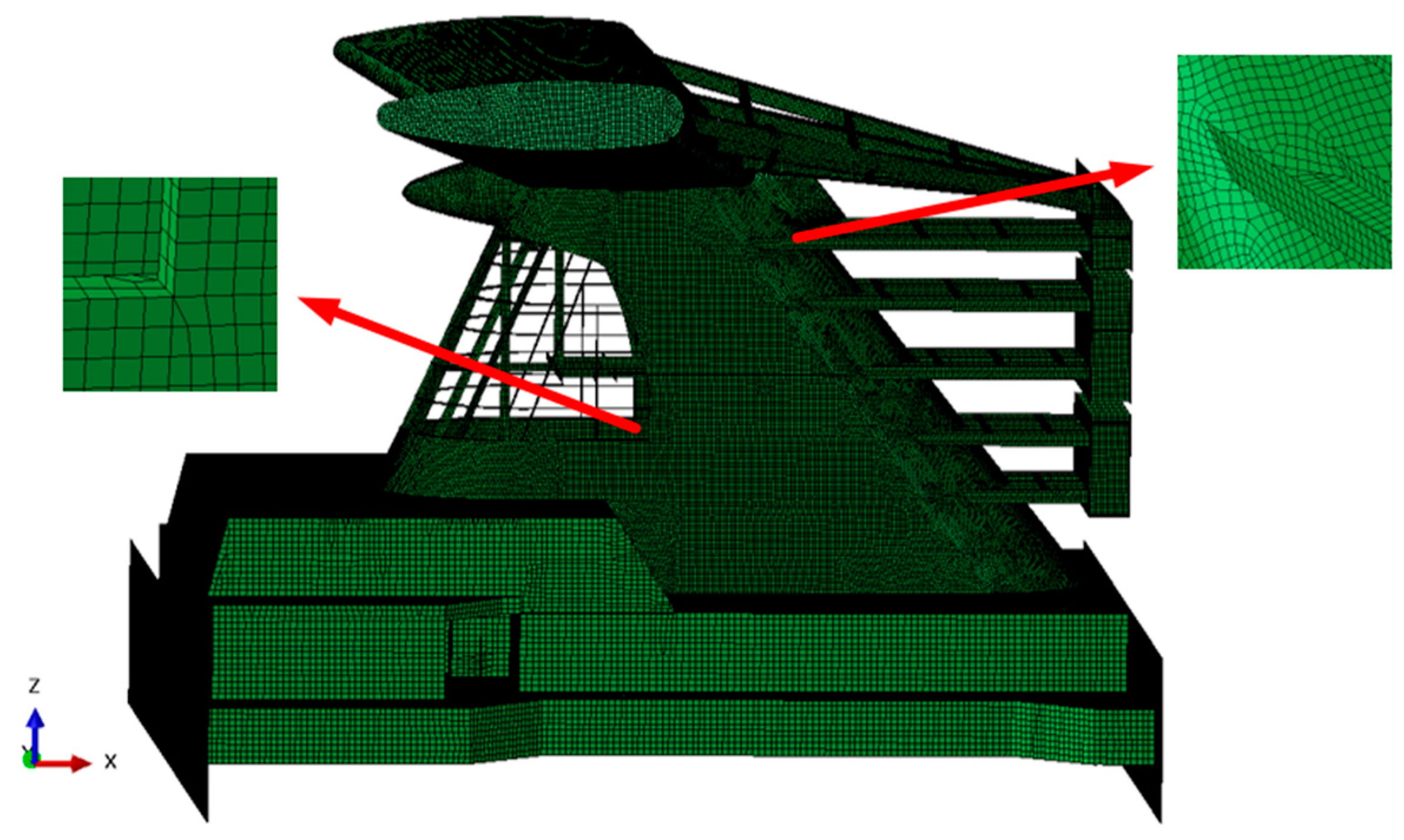
The numerical calculation of the funnel structures is conducted using finite element software ABAQUS 2021. Figure 6 displays the details of FE models. The explicit code is utilized to address the structural post-buckling and collapse phenomenon and takes into account the large plastic deformation. The finite element model is generated using S3R and S4R type shell elements. S3R and S4R type shell elements are 3 and 4-node, stress/displacement shell elements with reduced integration and large-strain formulation for tracking the large deformation [26]. The mesh size can have a significant effect on the uncertainty of the results obtained with finite element analysis. To obtain accurate numerical results, the meshes should be fine enough to well capture the yielding and local buckling process of the structure. However, finer meshes are accompanied by much greater consuming of computation efforts, which means that a balance between the mesh size and computing capability has to be made. Generally, more than 3 finite elements in the web of girders are generated, and the average element sizes of full-scale ship model for the refined parts and the scale model are 200 mm and 10 mm, respectively [27].
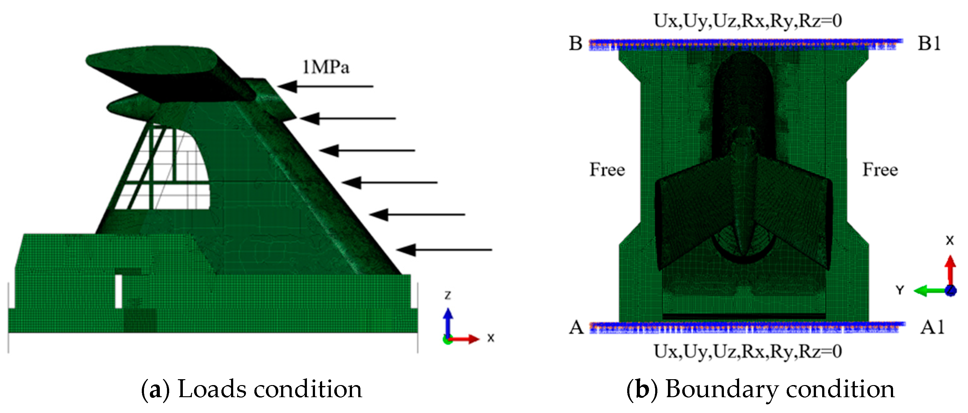
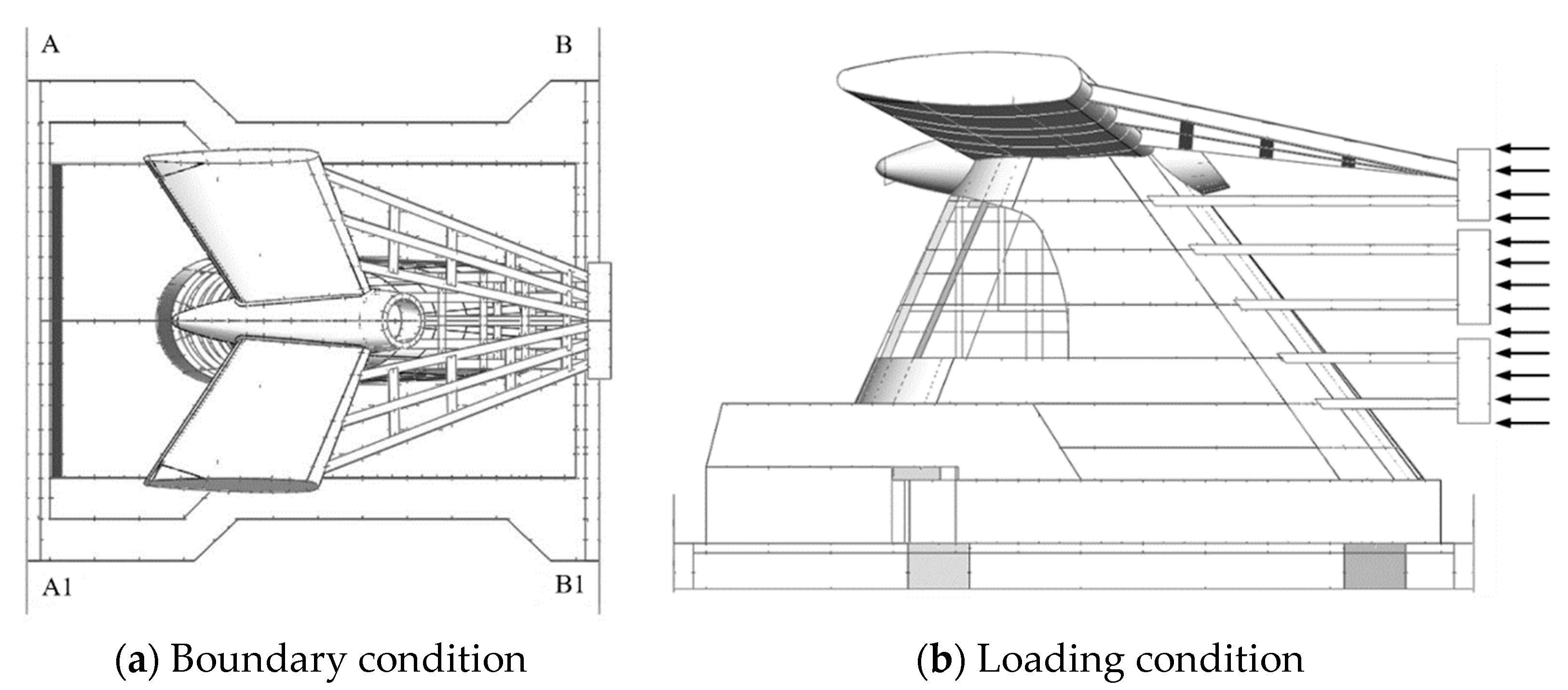
The loads and boundary conditions of the scaled model are shown in Figure 7. In this study, the uniform equivalent static wind pressure is adopted, and the surface pressure is applied on the windward side of the funnel structure to simulate the wind pressure. In engineering practice, wind action is often categorized into uniform wind and pulsating wind, and its load has a great relationship with waveform [28,29]. However, in the static linear and nonlinear analyses, the actual stochastic dynamic wind load is generally modeled as a quasi-static pressure with gusty wind effects [30]. When the transverse load acts on the funnel, the funnel plate on the windward side is directly damaged due to excessive pressure. However, when the longitudinal load acts on the funnel, due to the influence of the large opening, the main components buckle under the bending moment of the ultimate wind load, and the ultimate strength of the funnel under the transverse load is much greater than the longitudinal load. Therefore, the longitudinal load is selected in the experimental analysis. For actual ship structure, A-A1 and B-B1 are supported by bulkheads, which are connected with multiple decks, so the fixed boundary is adopted; A-B and A1-B1 are supported by strong beams, so simply supported boundaries are adopted. The scale model is simplified, A-B and A1-B1 directly support the upper deck through the side plate, so the two sides are free and convenient for test implementation. The x symbol represents the longitudinal direction of the ship.
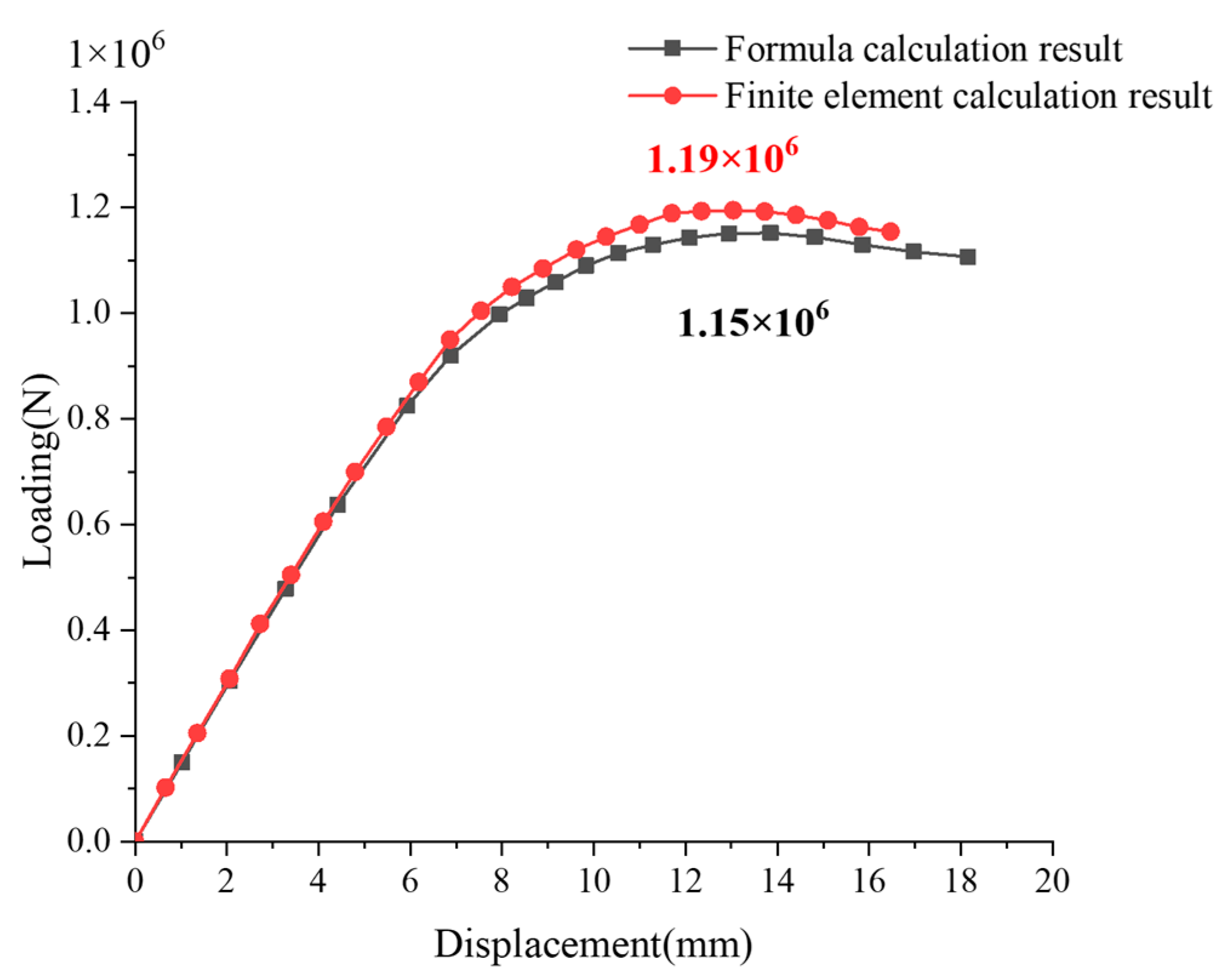
The finite element calculation shows that the ultimate wind load of the prototype structure is 2.88 × 10⁷ N, corresponding to the wind pressure of 0.38 MPa. According to the established similarity theory (Equation (1)), the ultimate load of the scaled model can be calculated as 1.15 × 10⁶ N (=2.88 × 10⁷/15/1.67 N).
The ultimate strength of scaled model is 1.19 × 10⁶ N, determined directly using the finite element method. Figure 8 shows load–deflection curves of the scaled model acquired through the application of the similar law and the finite element method. Observably, the ultimate strength of the scaled model, determined using the similarity formula, is comparable to the numerical value, with a discrepancy of 3.5%. The curves exhibit strong coherence within the elastic deformation. Nevertheless, it varies slightly during the plastic stage. In fact, some members are strengthened while some are removed during the model design, which causes an error in the structural carrying capacity. It can be found that under the same load, the displacement of the scale model determined by using the similar formula is smaller than that of the actually established scale model. It is mainly because the actually established scale model simplifies the internal components to some extent, resulting in the decrease in its stiffness.
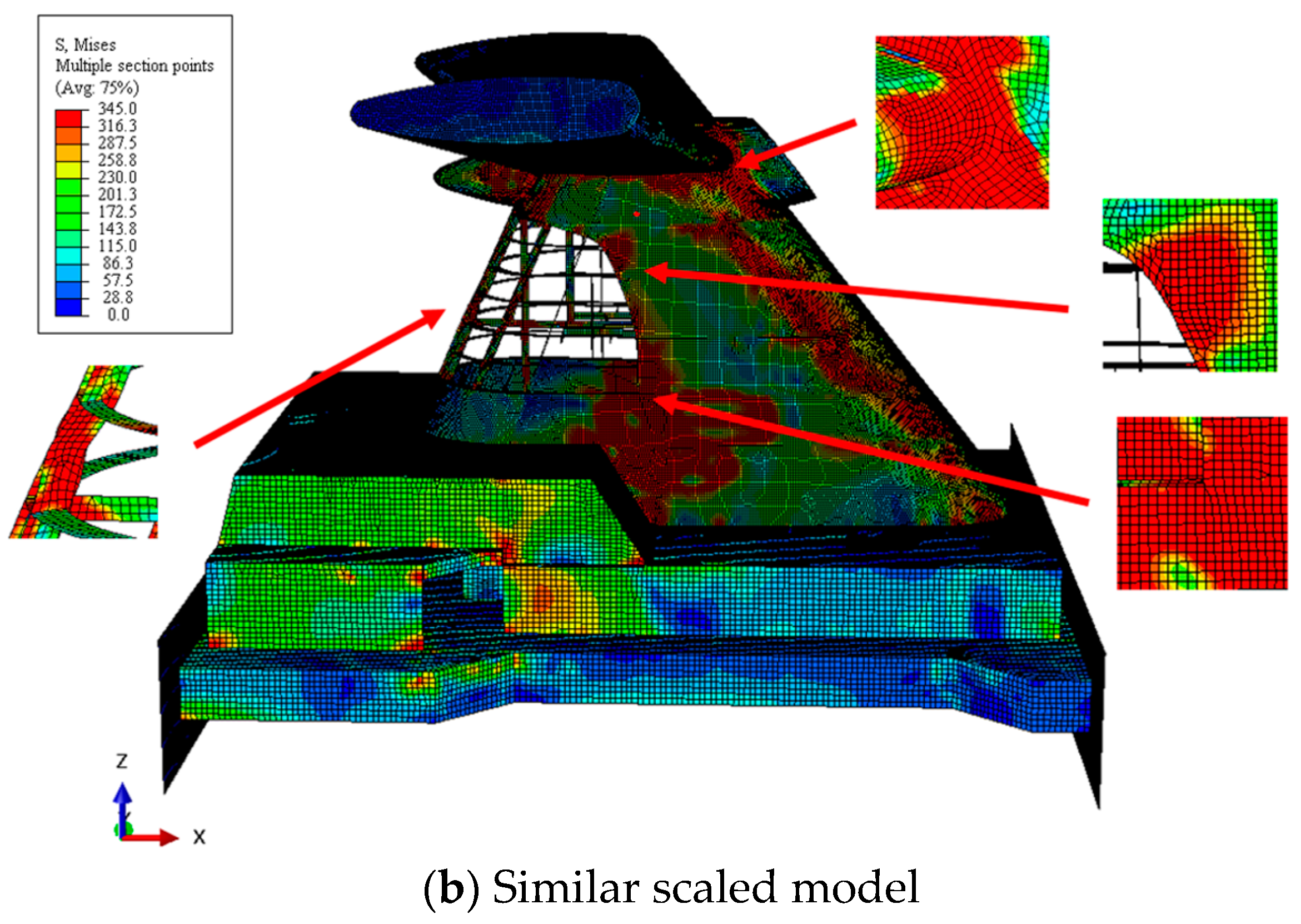
The final collapse modes of both the prototype structure and scaled model are presented in Figure 9. It shows that the funnel primarily collapses in the corner panels of the opening. At first, the plates of the funnel body that are exposed to the wind encounter significant tension, with the highest levels of stress mostly focused on the welding joints. As the load increases, the funnel body slopes toward the opening. Thus, the panels situated on the windward side suffer the tensile force, and the ones on the leeward side undergo the compressive force. Subsequently, buckling takes place in the plate and stiffener components adjacent to the opening. As the load increases, large plastic deformation occurs in the vulnerable cross-section, resulting in the complete failure of the structure.
Figure 10 shows that both models have the largest Y-direction deformation at the corner of the opening. This illustrates that the failure of the whole funnel under wind load is mostly attributed to the local buckling of the stiffened plates at the opening, which subsequently spreads to the adjacent members. Moreover, the finite element simulation confirms that the plastic deformation of both the full-scale ship structure and the test model is similar. Analyzing the loading and failure process of both models, it becomes evident that the scaled model precisely reflects the collapse characteristics of the real ship structure.
In order to replicate wind loading during the test process accurately, a rigid bracket (loading support) is welded to the windward side of the scaled model as shown in Figure 11. This bracket serves the purpose of applying hydraulic pressure upon itself, which is then dispersed into many concentrated forces acting on the welded joints. The stiffness of the bracket is much larger than that of the funnel model to prevent the failure of the loading support in the testing process. Figure 12 illustrates a comparison of the ultimate strength of the test model with and without the loading support. The ultimate strength value of the scaled model with the bracket is 1.24 × 10⁶ N, which is 4.2% larger than the unsupported model. This phenomenon is reasonable as the support is welded directly to the member’s joints, enhancing the strength of local structures. Within the allowable error, the provided support reinforces the model indeed. In the elastic region for both models, the two load–displacement curves exhibit a good agreement. During the plastic deformation stage, there is a minor variation in the ultimate load.
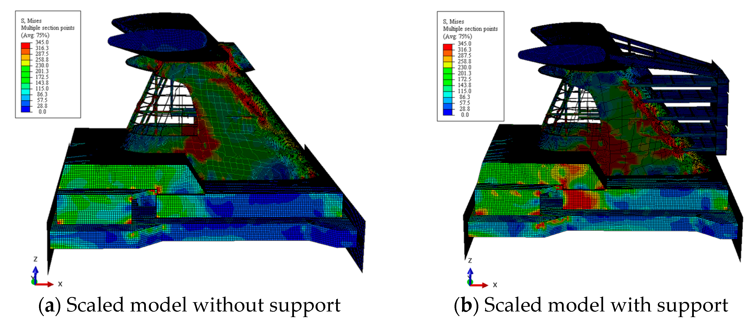
Figure 13 shows the ultimate collapse mode of these two models. The collapse deformation of both models exhibits consistency at the limit state. The funnel bodies both are displaced backward under the action of forces exerted on their entire surfaces. The front panel undergoes tensile force. The plate and stiffener members near the opening suffer compression, leading to buckling and plastic deformation of local plates. The specimens mainly undergo global failure as a result of plastic buckling occurring at the opening cross-section. The funnel falls as a result of sudden and substantial deformation of the structural elements near the aperture, leading to a significant reduction in the external wind load.

2.3. Experiment Setup

The applied boundary and loading conditions in the scaled test are shown in Figure 14. Edges A-A1 and B-B1 are clamped and edges A-B and A1-B1 are free. Six hydraulic cylinders are utilized to provide external horizontal forces on one end of the loading support, and the concentrated forces are distributed as forces acting on the surface of the funnel body through the welded joints. Each hydraulic cylinder can apply a load of 300 kN and is synchronously controlled through an oil pump. At the same time, the pressure sensor is used to measure the applied force.
In order to prevent the frame from toppling over, enclosed supporting beams are established in the testing process and huge triangular cantilevers are employed to limit the x displacement of the closed frame (Figure 15). Series of hydraulic cylinders are utilized to apply significant horizontal wind load. These hydraulic cylinders are simultaneously controlled by an oil pump system. In addition, a load transducer is incorporated to record the input loads precisely.
The steps involved in carrying out the experiment are described in the following manner. (1) In the initial stage, several cycles of loading and unloading procedures are carried out in order to partially release the residual stresses that were created in the welding process and reduce the gaps between the supporting beams. (2) Hydraulic cylinders are controlled to load the test specimen progressively and simultaneously until it collapses.

2.4. Tensile Test

The test model primarily consists of Q345 steel plates ranging in thickness from 3.0 mm to 5.0 mm. Its mass density is 7850 kg/m3, Young’s modulus is 210 MPa, and the Poisson’s ratio is 0.3. The tensile tests are carried out to acquire the material properties, as shown in Figure 16. The yield stresses of the steel materials, determined from the tensile results, are presented in Table 3.

2.5. Measuring Device Setup

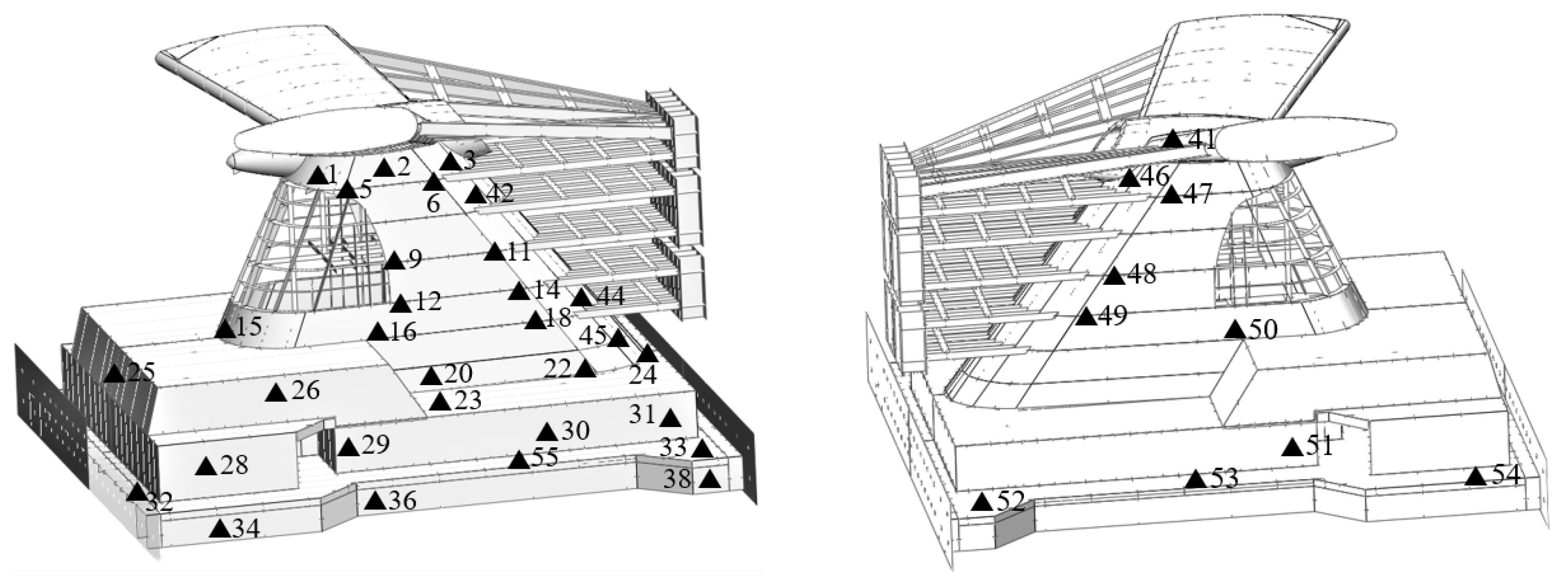
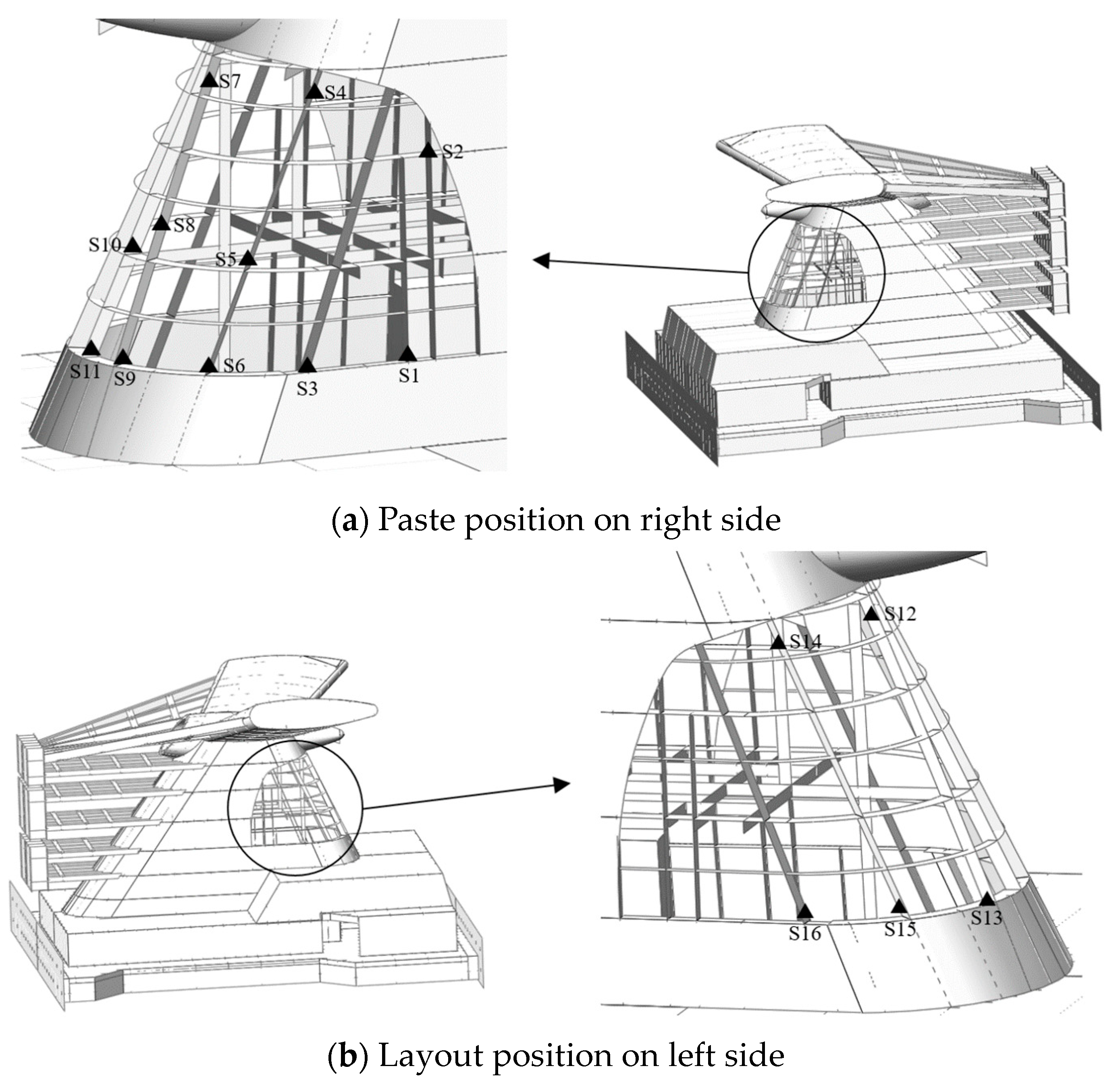
Figure 17 and Figure 18 illustrate the arrangement of strain gauges. These gauges are positioned in areas where large stress is concentrated, particularly at the region where welded joints buckle, areas with sudden and significant deformation, and the stiffeners of the opening. Prior to the experiment, finite element studies were performed to determine the locations of yield stresses for the test model.
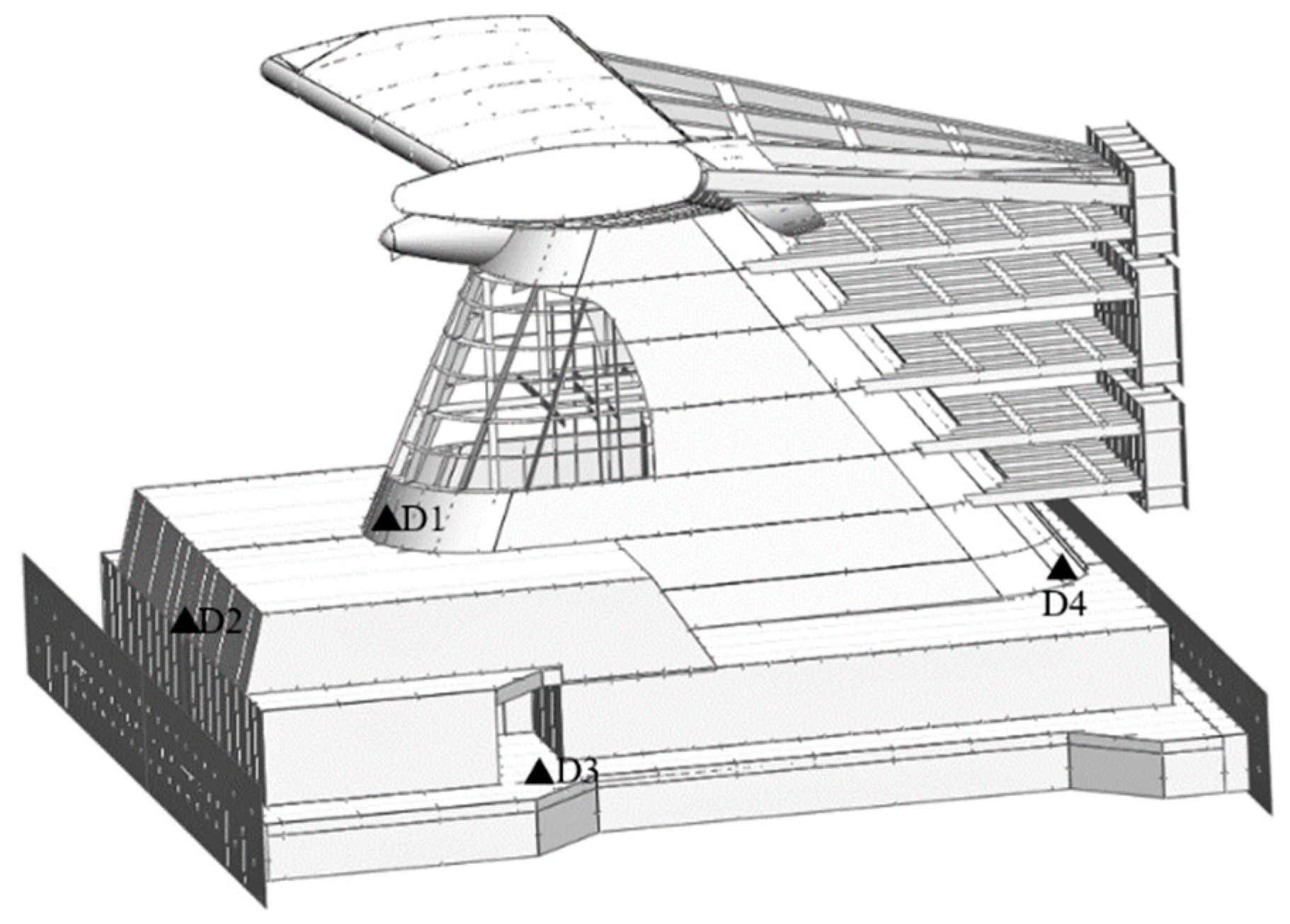
The layout of the displacement transducers is shown in Figure 19. Measuring points D1, D2 and D4 measure the horizontal displacement of the specimen caused by horizontal load, and D3 measuring point measures the out-of-plane deformation of the deck.

3. Experiment Results

3.1. Load–Displacement Relationship

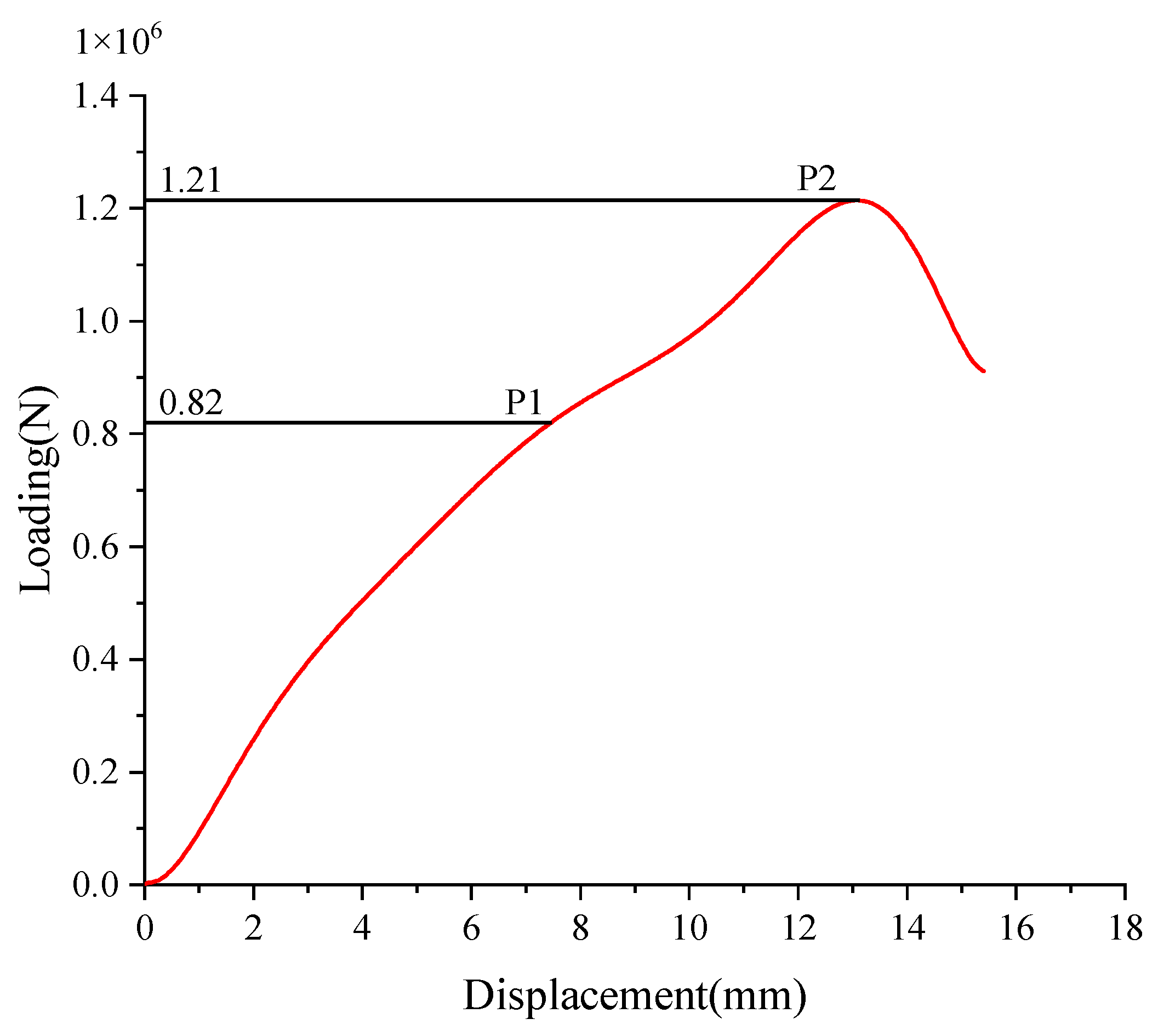
Figure 20 displays the load–displacement curve of the scaled model, representing the collapse process during the test. The resultant load value refers to the cumulative horizontal force applied by all the hydraulic cylinders, whereas the displacement value is recorded by the transducer of D4. The recorded maximum force during the experiment is 1210 kN, followed by the failure of the test model with a significant increase in deformation. It can be seen that the funnel structure shows an almost linear behaviour before point P1. It indicates that most members of the funnel are still within the elastic stage. When the external force increases about to 82 tons, intermittent noise occurs due to the plastic buckling of internal members. Before reaching the limit state point P2, it is obvious that the curve’s slope begins to decline as the load increases. It means that the bending stiffness of the test model decreases due to the local buckling and failure of members. As the hydraulic loads are progressively increased, the weakest part experiences severe deformation leading to the detachment of multiple strain gauges. This signifies that the test model has reached its ultimate condition.

3.2. Collapse Mode

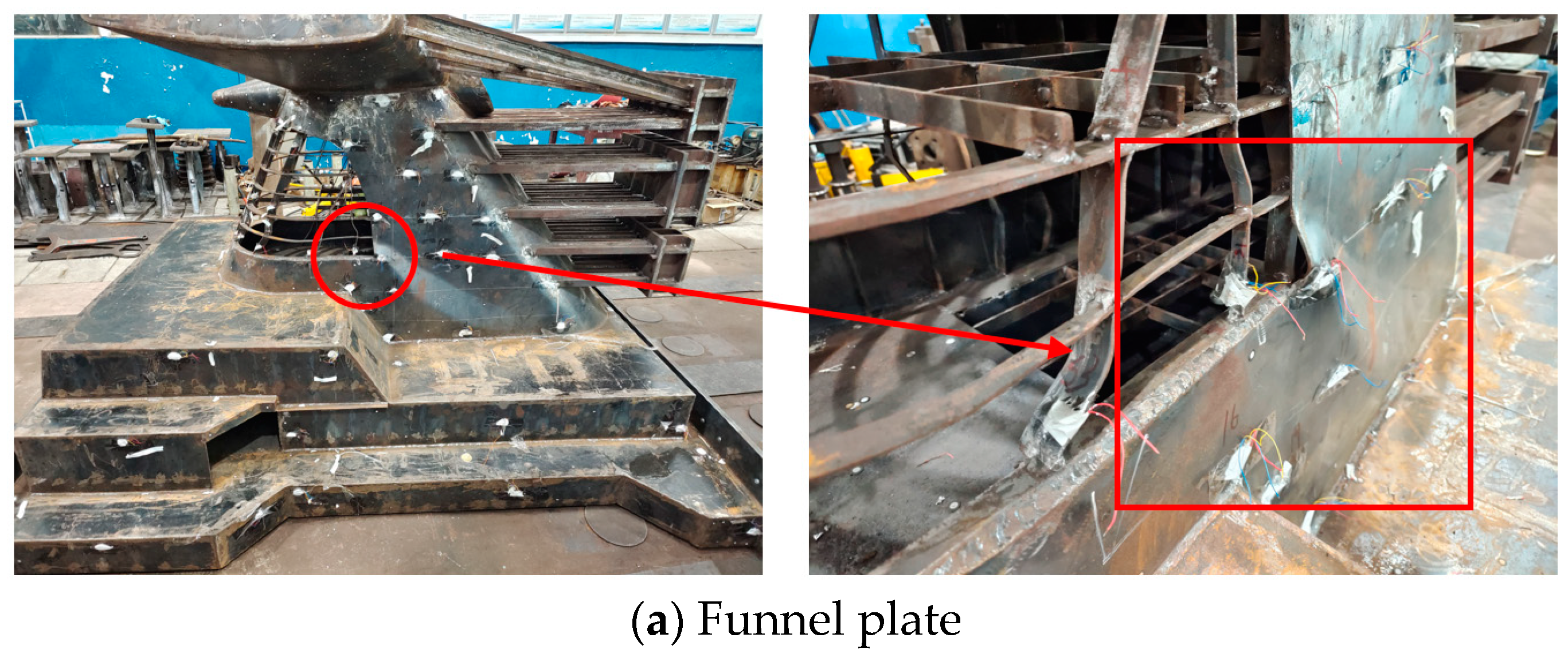
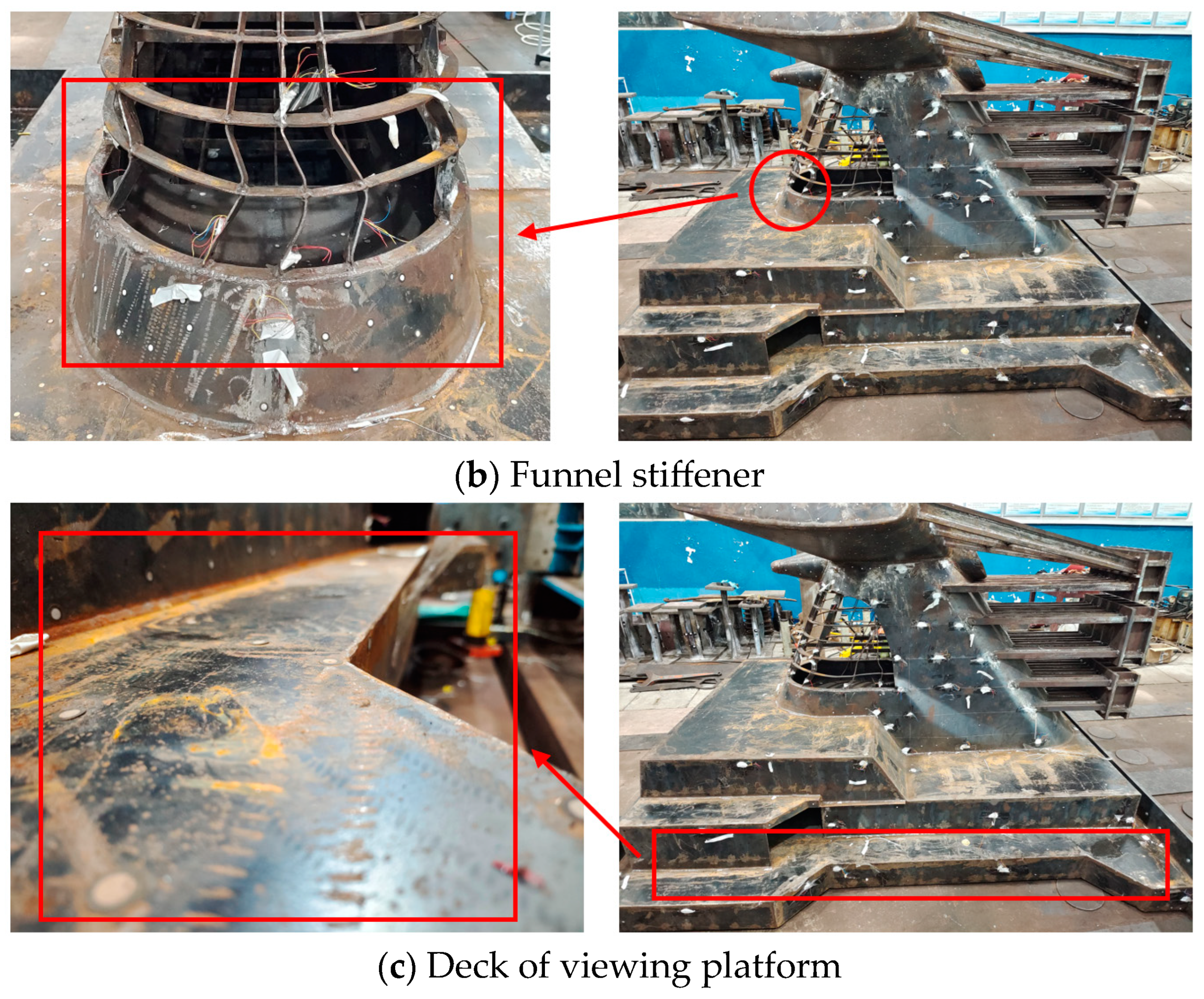
The specimen undergoes structural failure when subjected to a quick and substantial deformation, resulting in a considerable decrease in hydraulic forces. The large plastic deformation of local structures is shown in Figure 21. The sudden collapse of the funnel specimen is mostly due to plastic buckling occurring in its most vulnerable section. Under the action of horizontal wind pressure, the bottom section of the funnel body suffers the greatest bending moment, similar to that of a cantilever beam.
The primary occurrence of plastic failure in the funnel panel is concentrated in the opening corner. The local plates have large deflection when buckling happens. The propagation of buckling rapidly extends to the nearby panels, resulting in the tripping of stiffeners. Finally, the structure experiences plastic failure in the opening section (Figure 21a). The stiffeners within the opening exhibit significant buckling distortion and collapse at the bottom end (Figure 21b). The decks of the viewing platform supporting the funnel body do not show large deformations (Figure 21c). It is reasonable because the decks suffer out-of-plane stresses during the collapse process and the deck panels are hard to have buckling other than the ones of the funnel body suffering compressive stresses.

3.3. Stress Distribution

The von-Mises stress can be derived from the data collected by the strain gauges. The obtained results for partial yield region measured points are shown in Figure 22a,b, corresponding to the gauge arrangement in previous figures. The material yield stress is taken as the maximum value when the calculated stress is above this threshold, as the formulas rely on the linear elastic theory. It is evident that the stress initially rises at Point 5, located at the upper edge of the opening, due to the relatively low stiffness of the local structure. Point 12 exhibits the largest stress and experience buckling first, which is located at the opening corner, followed by large plastic deformation. The primary concentration of stresses occurs in the buckling zones (Points 12 and 16), with significantly higher strains present at the vertical stiffeners within the opening (S11 and S6). The stresses (Points 12 and 16) are mainly concentrated around the buckling regions, and much larger stresses exist at the vertical stiffeners in the opening (S11 and S6). A noticeable characteristic of sudden stress increase is detected at several points (Points 20 and S1). This abrupt shift in stresses and strains is caused by the buckling deformation of certain components, implying that the specimen suffers plastic buckling failure.
The strain gauge results are symmetrical with respect to the longitudinal direction of the scaled model (Points 3 and 45, Points 11 and 48, Points 33 and 52, S7 and S12 and S6 and S15; see Figure 17 and Figure 18), as shown in Figure 23. It is evident that the data from corresponding strain gauges are consistent throughout the testing process, suggesting that the applied load and deformation exhibit a satisfactory left–right symmetry, matching the criteria for a collapse test.
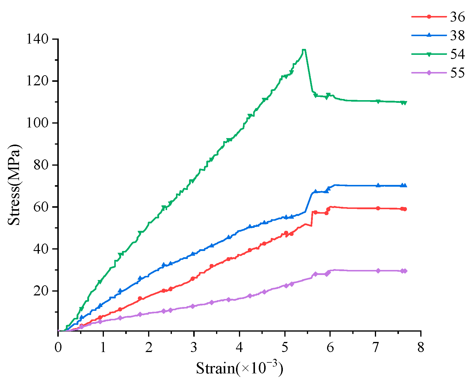
The strain gauge measurements taken from specific points of the deck (Points 36, 38, 54 and 55, as shown in Figure 17) are displayed in Figure 24. The obtained results from these points exhibit a linear change, indicating that the deck area of the test model is still in the elastic range, which corresponds to the previous results.

4. Comparison of the Experimental and Numerical Results

Experimental verification can be used to guarantee the precision of numerical computation outcomes. Firstly, the numerical load–displacement curve of the scaled model is compared to the experimental result in Figure 25. The ultimate strength value analyzed from the numerical simulation is 1.24 × 10⁶ N, while it is 1.21 × 10⁶ N in the experiment, with a difference of 2.4%. Within the model’s initial linear range, the two curves exhibit a strong concurrence. During the nonlinear stage, there is little discrepancy in predicting the ultimate strength, and the displacement obtained by the test is larger than that by the numerical analysis, with an error of 7.7%. At the beginning of the experiment, the funnel specimen undergoes multiple cycles of preloading and unloading processes to release the welding residual stress as well as reduce the gaps between the specimen and the supporting beam. However, the external force in the load–unload stage is not strong enough to eliminate the gaps in the specimen completely. The zero-displacement condition cannot be fully achieved in the experimental tests, which are applied in numerical analysis. In addition, some plates and stiffeners buckle seriously when subjected to loads closing to the limit state point. The test model experiences a sudden and significant deformation, leading to extensive destruction of the scaled model in a short period of time, which complicates the process of collecting data. Moreover, since the initial deflection and the residual welding stress cannot be recorded completely in the numerical analysis, there are discrepancies in the local buckling behaviour of some components. In any case, the finite element results are valid compared to the experimental ones with an acceptable margin of error. According to the similarity law, the ultimate strength value of the actual funnel can be predicted by using Equation (1), which is 3.01 × 10⁷ N (=1.21 × 106 × 15 × 1.67 N).

5. Discussion

This discussion focuses on the specific characteristics that significantly impact the ultimate strength of funnel structures, such as the influence of the large opening, the primary constituting members, and local reinforcements. The instances and outcomes that were studied are listed in Table 4.

5.1. Effect of Reinforced Stiffeners

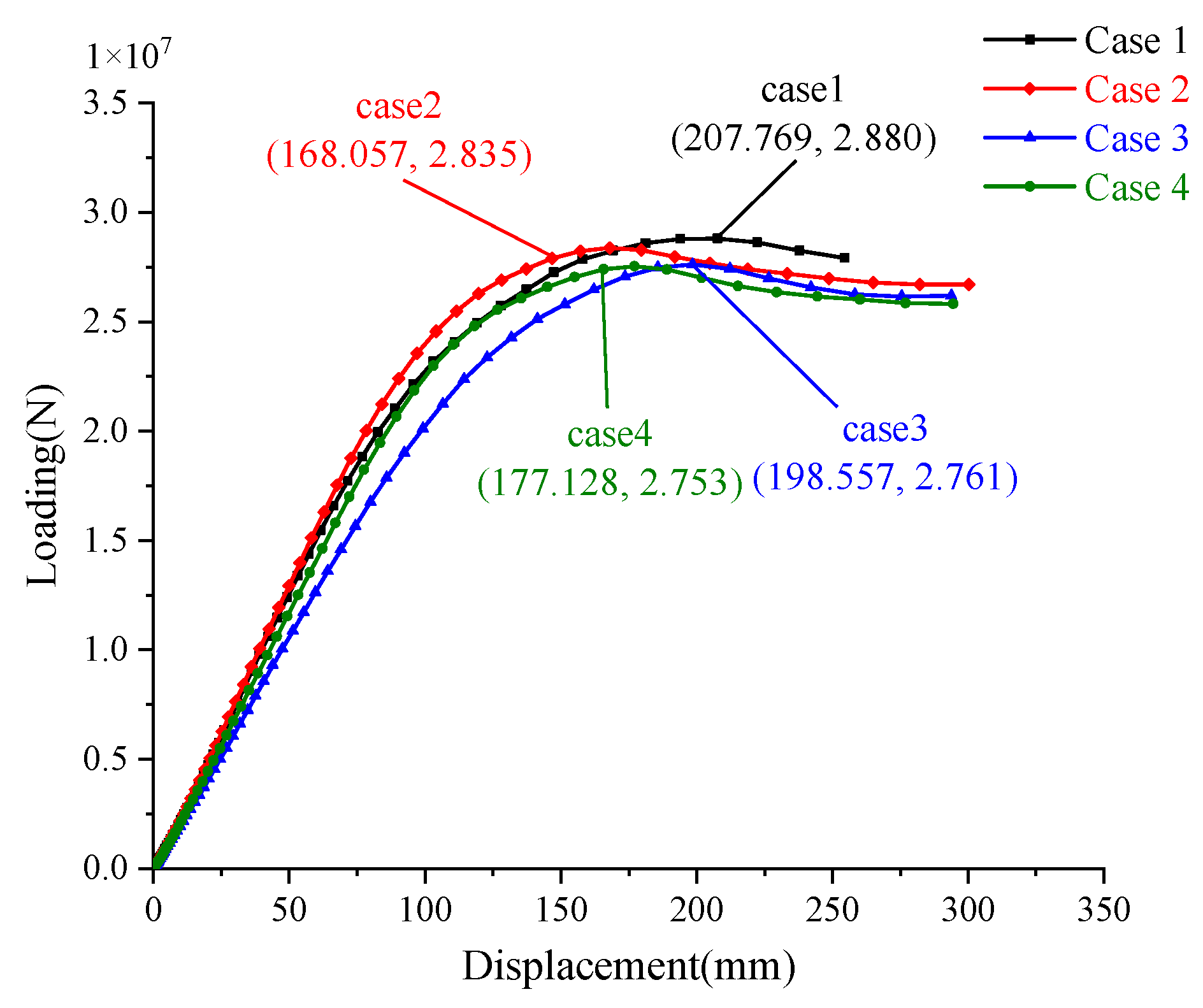
Additional finite element simulations are performed to examine the impact of the reinforcements surrounding the large opening on the ultimate strength of the funnel, as outlined in Cases 1–4 described in Table 4. A comparison of the load–displacement relationship is presented in Figure 26. By comparing Case 1 to Case 4, it shows that the ultimate strength is reduced by 4.4%. Upon analyzing the arrangement of reinforcement in the opening, it is found that the ultimate strength of the funnel with only vertical reinforcement decreases by 1.6% (Cases 1 and 2), while that with only transverse reinforcement decreases by 4.1% (Cases 1 and 3). It is analyzed that the plates and the stiffeners near the opening fail due to buckling under wind pressure. Thus, the vertical reinforcements can effectively improve the buckling strength other than the transverse ones.

5.2. Effect of Member Thickness

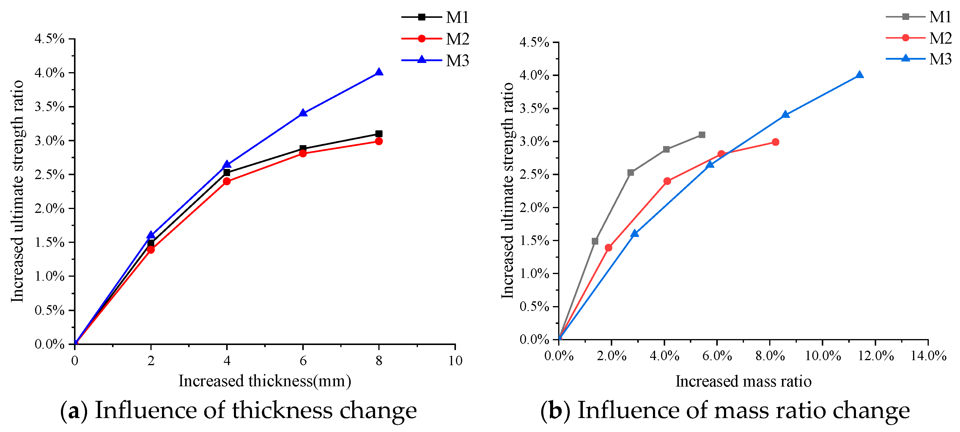
Figure 27a illustrates the correlation between the ultimate strength and the thickness of the member. The enhancement in the funnel’s strength is somewhat more pronounced when increasing the plate thickness (Case M1) compared to increasing the reinforcement thickness (Case M2). When the increased thickness exceeds 4 mm, the growth rate of the ultimate strength of M1 and M2 decreases significantly. The ultimate strength of the funnel in case M3 does not increase largely compared to that in case M1 and M2 when the extra thickness is below 4 mm. However, the growth rate of the ultimate strength in case M3 has no remarkable decease when the increased thickness exceeds 4 mm. The relationship between the increased ultimate strength and member mass is shown in Figure 27b. It is obvious that the increasing strength per unit weight in Case M1 is much larger than the other two cases. Therefore, it is better to improve the funnel’s strength by applying larger plate thickness. As the mass grows, the expansion rate of the structural strength slows down in the cases of M1 and M2. It implies that several members should be simultaneously strengthened in order to compensate for this effect.

5.3. Effect of the Large Opening

The ultimate strength of the funnel with no large aft opening is also analyzed using the FE method. Figure 28a shows the load–displacement curves, whereas Figure 28b illustrates the failure behaviour of the intact one. It can be seen that the opening reduces the ultimate strength by around 29.2%. When the opening is enclosed, the plastic buckling of the intact specimen primarily occurs at the joints between the top wings and the funnel body, marked in yellow lines. In order to improve the resistance of the funnel structure against buckling, it is essential to augment the rigidity of the open cross-section to match that of the closed cross-section.

6. Conclusions

In this study, both the experimental test and finite element calculation are conducted to assess the ultimate strength of a large passenger ship’s funnel structure under wind load, which reveals the collapse pattern of the ship’s funnel with openings. It introduces a comprehensive experiment for evaluating the ultimate strength of a similarly scaled funnel model under wind pressure. It illustrates the mechanical behaviour related to the ultimate strength and the step-by-step collapse of the ship funnel. Additionally, the corresponding numerical simulation is performed, and the numerical results match closely the experimental data in terms of the load–displacement curves, plate deformation and stresses. From the findings of the experimental and numerical analyzes, several key insights are concluded as follows:
(1)
The designed testing device is valid to apply large wind loads, and the scaled model can accurately present the progressive collapse process of the ship funnel subjected to wind pressure, with an error of 3.5% for predicting the ultimate strength value. The collapse patterns of structures observed in the experiment coincide with those derived from numerical analysis.
(2)
The presence of a large opening significantly alters the collapse pattern of the funnel structure, reducing its ultimate strength by 29.2%. The buckling deformation primarily occurs at the opening’s corner, followed by the sudden collapse of the specimen due to plastic deformation at the opening cross-section. The funnel tends to lean backward like a cantilever beam under horizontal wind pressure. The plates and stiffeners near the opening are prone to buckling under compression, and the side plates facing the wind are subjected to tensile stress.
(3)
Reinforcing the members surrounding the aperture increases the bending stiffness of the opening section and finally enhances the funnel’s ultimate strength. Thickening the plate material is found to be more effective than merely increasing the thickness of internal stiffeners. The optimal approach for improving structural strength involves ensuring the open section has comparable stiffness to the closed ones, thereby shifting the buckling region to the structures far from the opening. This principle is crucial for the optimal design of structures with inevitable openings.
At present, the research conducted in this paper is based on the equivalent static wind load, and it is evenly distributed on the windward side of the funnel. But besides the static component, the wind pressure also has a pulsation component. As the chimney has a complex shape, the distribution of wind pressure over its surface differs significantly from uniform. In the future, CFD software (ANSYS Fluent 2023 R1) complexes can be used to carry out these studies.

Author Contributions

Conceptualization, Z.D. and L.A.; methodology, Z.D.; software, Z.D.; validation, L.A.; writing—original draft preparation, Z.D.; writing—review and editing, L.A., B.L., Z.P., Q.T. and W.W.; supervision, L.A., B.L. and Z.P. All authors have read and agreed to the published version of the manuscript.

Funding

This research was funded by The general project of the National Natural Science Foundation of China, grant number 52301385, The Fundamental Research Funds for the Central Universities, grant number WUT:223173003.

Institutional Review Board Statement

Not applicable.

Informed Consent Statement

Not applicable.

Data Availability Statement

The data supporting the reported results cannot be shared at this time, as it were used in producing more publications on this research.

Acknowledgments

This work was supported by Hubei Provincial Engineering Research Center on Green & Smart River-sea-going Ship, China.

Conflicts of Interest

The authors declare no conflicts of interest.

References

  1. Janssen, W.D.; Blocken, B.; van Wijhe, H.J. CFD simulations of wind loads on a container ship: Validation and impact of geometrical simplifications. J. Wind. Eng. Ind. Aerodyn. 2017, 166, 106–116. [Google Scholar] [CrossRef]
  2. Bahatmaka, A.; Kim, D.; Prabowo, A. Numerical Investigation against Laboratory Experiment: An Overview of Damage and Wind Loads on Structural Design. Procedia Struct. Integr. 2020, 27, 6–13. [Google Scholar] [CrossRef]
  3. Chou, J.; Chiu, C.; Huang, I.; Chi, K.-N. Failure analysis of wind turbine blade under critical wind loads. Eng. Fail. Anal. 2013, 27, 99–118. [Google Scholar] [CrossRef]
  4. Ishihara, T.; Yamaguchi, A.; Takahara, K.; Mekaru, T.; Matsuura, S. An analysis of damaged wind turbines by typhoon maemi in 2003. In Proceedings of the Sixth Asia-Pacific Conference on Wind Engineering, Seoul, Republic of Korea, 12–14 September 2005. [Google Scholar]
  5. Bajic, D. Structural design of passenger cruise ships—An introduction to classification requirements. Ships Offsh Struct. 2015, 10, 232–238. [Google Scholar] [CrossRef]
  6. Jebsen, J.J.; Papakonstantinou, V.C. Evaluation of the Physical Risk of Ship Grounding. Master’s Thesis, Massachusetts Institute of Technology, Cambridge, MA, USA, 1997. [Google Scholar]
  7. Wang, P.; Wang, F.; Chen, Z. Investigation on aerodynamic performance of luxury cruise ship. Ocean. Eng. 2020, 213, 107790. [Google Scholar] [CrossRef]
  8. Doan, V.T.; Liu, B.; Garbatov, Y.; Wu, W.; Guedes Soares, C. Strength assessment of aluminium and steel stiffened panels with openings on longitudinal girders. Ocean. Eng. 2020, 200, 107047. [Google Scholar] [CrossRef]
  9. Zhou, B.; Han, X.; Guo, W.; Liu, Y.; Tan, S.K. Numerical and experimental study on cutting access opening in ship structure. J. Ship Prod. Des. 2017, 33, 12–23. [Google Scholar] [CrossRef]
  10. Zhao, Z.; Zhang, M.; Gao, Y.; Sun, Q. Investigations on shear capacity of steel plates with local opening. J. Constr. Steel Res. 2021, 179, 106518. [Google Scholar] [CrossRef]
  11. Liu, B.; Du, X.K.; Gan, J.; Ao, L.; Wu, W.; Soares, C.G. Experimental and numerical analysis of the ultimate compressive strength of double-deck structures with a large opening. Ships Offshore Struct. 2022, 17, 2788–2801. [Google Scholar] [CrossRef]
  12. Liu, B.; Gao, L.J.; Ao, L.; Wu, W. Experimental and numerical analysis of ultimate compressive strength of stiffened panel with openings. Ocean. Eng. 2021, 220, 108453. [Google Scholar] [CrossRef]
  13. Morshedsolouk, F.; Khedmati, M.R. An extension of coupled beam method and its application to study ship’s hull-superstructure interaction problems. Lat Am J Solids Struct. 2011, 8, 265–290. [Google Scholar] [CrossRef]
  14. Romanoff, J.; Remes, H.; Varsta, P.; Jelovica, J.; Klanac, A.; Niemelä, A.; Bralic, S.; Naar, H. Hull-superstructure interaction in optimised passenger ships. Ships Offshore Struct. 2012, 8, 612–620. [Google Scholar] [CrossRef]
  15. Yao, T.; Fujikubo, M.; Yanagihara, D.; Fujii, I.; Matsui, R.; Furui, N.; Kuwamura, Y. Buckling collapse strength of ship carrier under longitudinal bending (1st Report). J. Soc. Nav. Archit. Jpn. 2002, 191, 255–264. [Google Scholar] [CrossRef]
  16. Benson, S.; AbuBakar, A.; Dow, R.S. A comparison of computational methods to predict the progressive collapse behaviour of a damaged box girder. Eng. Struct. 2013, 48, 266–280. [Google Scholar] [CrossRef]
  17. Hirdaris, S.E.; Bai, W.; Dessi, D.; Ergin, A.; Gu, X.; Hermundstad, O.A.; Huijsmans, R.; Iijima, K.; Nielsen, U.; Parunov, J.; et al. Loads for use in the design of ships and offshore structures. Ocean. Eng. 2014, 78, 131–174. [Google Scholar] [CrossRef]
  18. Quispe, J.P.; Estefen, S.F.; de Souza, M.I.L.; Chujutalli, J.H.; Amante, D.D.A.M.; Gurova, T. Numerical and experimental analyses of ultimate longitudinal strength of a small-scale hull box girder. Mar. Struct. 2022, 85, 103273. [Google Scholar] [CrossRef]
  19. Pei, Z.Y.; Yuan, Q.N.; Ao, L.; Wu, W. A research on similarity law for combined ultimate bending and torsional strength. Ships Offshore Struct. 2023, 1–12. [Google Scholar] [CrossRef]
  20. Kulkarni, P.R.; Singh, S.N.; Seshadri, V. Parametric Studies of Exhaust Smoke–superstructure Interaction on a Naval Ship Using CFD. Comput Fluids. 2007, 36, 794–816. [Google Scholar] [CrossRef]
  21. Chen, Q.; Yin, Q.; Fan, A.; Sun, X.; Mou, X. Research on the calculation methods of wind load coefficients of inland cruise ship. In Proceedings of the 2015 International Conference on Transportation Information and Safety (ICTIS), Wuhan, China, 25–28 June 2015; pp. 871–876. [Google Scholar]
  22. Zhang, J.F.; Pei, H.; Li, J.; Ge, Y.J.; Zhao, L. Failure process and ultimate strength of RC hyperbolic cooling towers under equivalent static wind loads. Thin-Walled Struct. 2022, 176, 109307. [Google Scholar] [CrossRef]
  23. Bhatt, M.; Vasanwala, S.A. Ultimate Strength of RC Chimney Section under Monotonic Loading. J. Eng. Proj. Prod. Manag. 2022, 12, 217–223. [Google Scholar]
  24. Wang, C.; Wu, J.; Wang, D. Experimental and numerical investigations on the ultimate longitudinal strength of an ultra large container ship. Ocean. Eng. 2019, 192, 106546. [Google Scholar] [CrossRef]
  25. Zhang, S.; Khan, I. Buckling and ultimate capability of plates and stiffened panels in axial compression. Mar. Struct. 2009, 22, 791–808. [Google Scholar] [CrossRef]
  26. Dassault, S. Abaqus Analysis User’s Guide; Dassault Systèmes Simulia Corp.: Providence, RI, USA, 2014. [Google Scholar]
  27. Wang, Q.; Wang, C.; Wu, J.; Wang, D. Investigations on the torsional failure characteristics of the global hull girder with large deck openings. Ocean Eng. 2020, 198, 107007. [Google Scholar] [CrossRef]
  28. Jimenez-Martinez, M.; Varela-Soriano, J.; Carreón, J.; Torres-Cedillo, S.G. Waveform load analysis for fatigue in the printed PLA. Heliyon 2023, 9, e18480. [Google Scholar] [CrossRef]
  29. Hoang, T.; Duhamel, D.; Foret, G. Wave finite element method for waveguides and periodic structures subjected to arbitrary loads. Finite Elem. Anal. Des. 2020, 179, 103437. [Google Scholar] [CrossRef]
  30. Liang, Y.; Ren, X. Failure analysis and curvature-based failure criterion of super large cooling tower under strong equivalent static wind load. Eng. Fail. Anal. 2022, 142, 106801. [Google Scholar] [CrossRef]
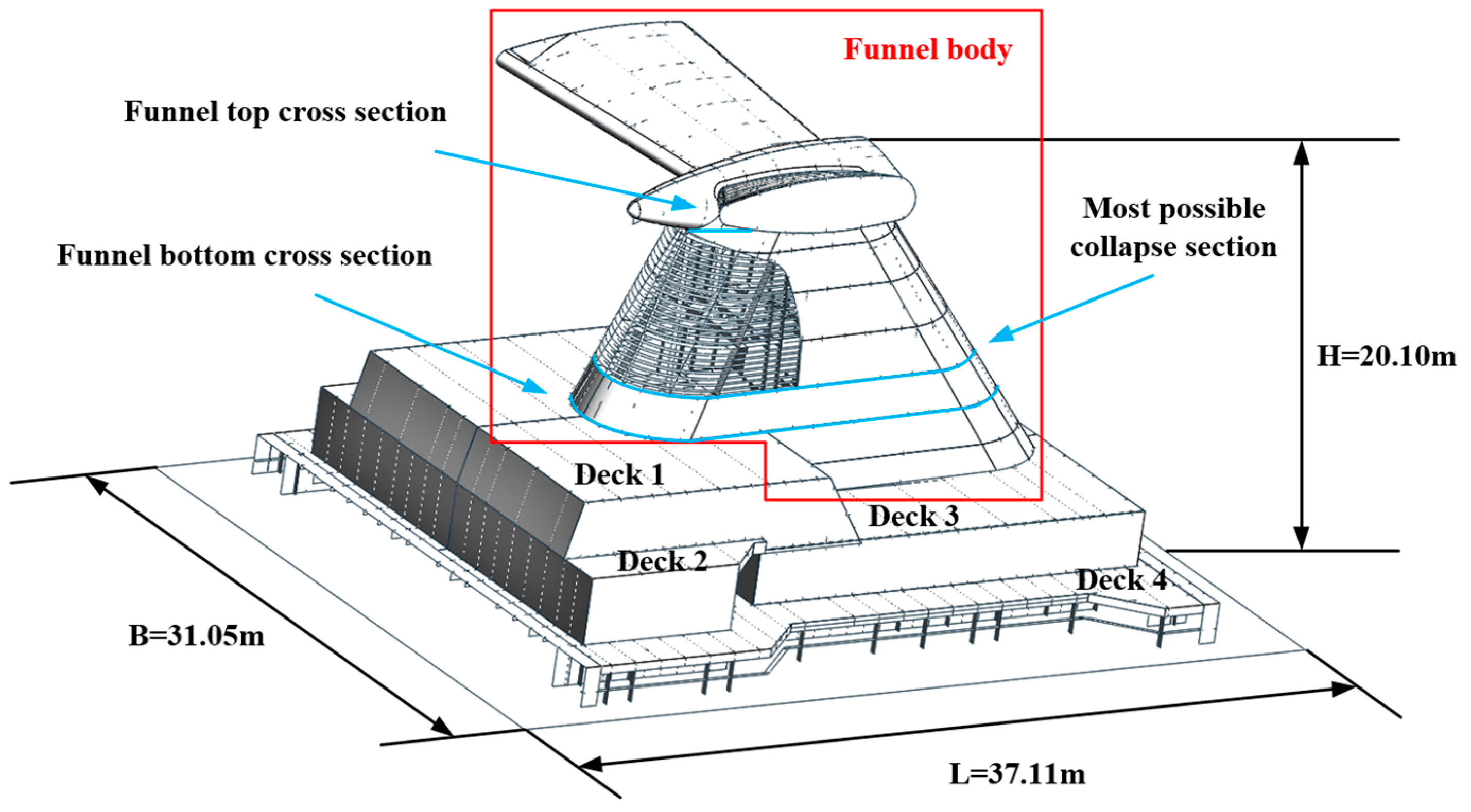
Figure 1. The main dimensions and compositions of funnel.
Jmse 12 00041 g001
Figure 2. Comparison of cross-sections of Decks 1, 2 and 4.
Jmse 12 00041 g002
Figure 3. Comparison of cross-sections of Decks 3 and 4.
Jmse 12 00041 g003
Figure 4. Dimensions of funnel top cross-section.
Jmse 12 00041 g004
Figure 5. Geometry properties of plates and stiffeners.
Jmse 12 00041 g005
Figure 6. The numerical model of the funnel.
Jmse 12 00041 g006
Figure 7. Loads and boundary conditions of the funnel.
Jmse 12 00041 g007
Figure 8. Load–displacement curves obtained by finite element analysis.
Jmse 12 00041 g008
Figure 9. Stress distribution of two funnel models.
Jmse 12 00041 g009aJmse 12 00041 g009b
Figure 10. Y direction deformation of two funnel models.
Jmse 12 00041 g010aJmse 12 00041 g010b
Figure 11. The FE model of the scaled model with support.
Jmse 12 00041 g011
Figure 12. Load–displacement curves of scaled models with and without support.
Jmse 12 00041 g012
Figure 13. Numerical overall collapse of two scaled models.
Jmse 12 00041 g013
Figure 14. The boundary and loading conditions of the model test.
Jmse 12 00041 g014
Figure 15. The collapse experiment setup.
Jmse 12 00041 g015
Figure 16. Stress–strain curve of test specimens.
Jmse 12 00041 g016
Figure 17. Layout of strain gauge on panel.
Jmse 12 00041 g017
Figure 18. Layout of strain gauge on stiffeners.
Jmse 12 00041 g018
Figure 19. Layout of displacement transducers.
Jmse 12 00041 g019
Figure 20. Load–displacement curve from the model test.
Jmse 12 00041 g020
Figure 21. The deformation of the model.
Jmse 12 00041 g021aJmse 12 00041 g021b
Figure 22. Average stress–strain relationship of the model.
Jmse 12 00041 g022
Figure 23. Test model symmetry check.
Jmse 12 00041 g023
Figure 24. Measuring point on deck.
Jmse 12 00041 g024
Figure 25. Comparison of load–displacement curves between numerical and experimental results.
Jmse 12 00041 g025
Figure 26. Influence of reinforced opening.
Jmse 12 00041 g026
Figure 27. Influence of different factors on ultimate strength ratio. M1 represents thickening the plate only; M2 represents thickening the stiffener only; M3 represents thickening the plate and the stiffener at the same time.
Jmse 12 00041 g027
Figure 28. Influence of large opening.
Jmse 12 00041 g028aJmse 12 00041 g028b
Table 1. Comparison of cross-section properties of the actual funnel to a scaled model.
SectionParametersActual ShipSimilar TransformationModelError
Deck 1Section area (mm2)93,519.33740.83904.54.4%
Position of neutral axis (mm)357.023.824.52.8%
Inertia moment about neutral axis (mm4)5.2 × 10109.2 × 1068.9 × 1063.1%
Deck 2Area (mm2)116,506.84660.34885.54.8%
Position of neutral axis (mm)311.420.820.51.2%
Inertia moment about neutral axis (mm4)6.3 × 10101.1 × 1061.1 × 1060.4%
Deck 3Section area (mm2)104,539.54181.64353.54.1%
Position of neutral axis (mm)451.130.130.41.1%
Inertia moment about neutral axis (mm4)6.1 × 10101.1 × 1061.1 × 1064.6%
Deck 4Section area (mm2)137,016.05480.65736.04.7%
Position of neutral axis (mm)202.513.513.60.5%
Inertia moment about neutral axis (mm4)2.5 × 10104.5 × 1064.4 × 1060.8%
Funnel bottom cross sectionSection area (mm2)417,581.216,703.316,252.32.7%
Moment of inertia (mm4)4.6 × 10128.2 × 1087.9 × 1083.0%
Funnel top cross sectionSection area (mm2)202,448.38097.97807.73.6%
Moment of inertia (mm4)1.4 × 10122.4 × 1082.5 × 1085.1%
Table 2. Comparison of nonlinear properties.
Members β p / β m λ p / λ m σ u p σ y p / σ u m σ y m
(Formula)
σ u p σ y p / σ u m σ y m
(FEA)
The stiffened panel of deck12.23/2.010.87/0.880.62/0.640.64/0.65
The stiffened panel of funnel body2.05/1.961.36/1.370.43/0.430.39/0.41
Table 3. Yield stress of the steel materials.
ThicknessYield Stress (MPa)
3 mm335.4
4 mm348.6
5 mm359.4
Table 4. The lists of the selected scenarios.
CaseReinforced OpeningStiffener ThicknessPlate ThicknessUltimate Strength
1V + T10 mm5 mm2.880 × 107 N
2V10 mm5 mm2.835 × 107 N
3T10 mm5 mm2.761 × 107 N
4 10 mm5 mm2.753 × 107 N
5V + T10 mm7 mm2.923 × 107 N
6V + T10 mm9 mm2.953 × 107 N
7V + T10 mm11 mm2.963 × 107 N
8V + T10 mm13 mm2.969 × 107 N
9V + T12 mm5 mm2.920 × 107 N
10V + T14 mm5 mm2.949 × 107 N
11V + T16 mm5 mm2.961 × 107 N
12V + T18 mm5 mm2.966 × 107 N
13V + T12 mm7 mm2.926 × 107 N
14V + T14 mm9 mm2.956 × 107 N
15V + T16 mm11 mm2.978 × 107 N
16V + T18 mm13 mm2.996 × 107 N
Note: V and T represent the vertical and transverse reinforcements, respectively.
Disclaimer/Publisher’s Note: The statements, opinions and data contained in all publications are solely those of the individual author(s) and contributor(s) and not of MDPI and/or the editor(s). MDPI and/or the editor(s) disclaim responsibility for any injury to people or property resulting from any ideas, methods, instructions or products referred to in the content.