Abstract
This paper presents an improved motion controller based on the backstepping method to address nonlinear control challenges in unmanned aerial–aquatic vehicles (UAAVs), enabling them to navigate between two different media. The nonlinear control approach is applied to UAAV motion control, incorporating filters to improve stability. The study designs motion controllers for three UAAV phases: underwater, in the air, and transitioning between media. Fluid simulations of the emergence process of the UAAV for future field experiments were conducted. By fine-tuning the simulations, a comprehensive understanding of the vehicle’s performance is obtained, offering crucial insights for the development of subsequent control systems. Simulation results confirm the controller’s ability to achieve target trajectory tracking with control system responses that meet practical requirements. The controller’s performance in attitude control and trajectory tracking is verified in underwater gliding, transmedia transitions, and airborne phases, demonstrating its effectiveness.
1. Introduction
In recent years, the escalating demand for marine resources has elevated the role of unmanned vehicles (UVs) as key platforms in areas such as water monitoring, environmental protection, and military operations. The diverse functionality of UV has a direct impact on the operational efficiency of engineering tasks. Consequently, researchers are increasingly focusing on the design of UVs that are adaptable to different mission scenarios [1,2,3]. To better explore marine resources and meet military requirements, nations around the world are actively developing innovative unmanned platforms. Traditional UVs, however, operate predominantly in a single medium, making it difficult to adapt to the growing complexity of mission requirements. To address this challenge, unmanned aerial–aquatic vehicles (UAAV) have emerged that are capable of operating in both aerial and aquatic environments. UAAVs combine the advantages of underwater robot concealment with the rapid mobility of UAAVs [4,5,6]. This dual-medium capability not only expands their operational scope but also increases their efficiency. The development of UAAVs has significant research value, bridging the gap between single-medium UV and meeting critical needs in both military and civilian applications.
Considering that the motion control workspace of traditional UVs is generally in a single medium and that the model parameters and control parameters related to the UV and the medium do not change much, the past research on the motion control of the aerial vehicle in a single medium is difficult to adapt to the needs of UAAVs and to meet the requirements of the control of the two different mediums across the water and the air [7]. The research of UAAVs is in the beginning stage, and the main research focuses on the shape and structure design of UAAVs, the water discharge method, and the prototype production experiment; the control of UAAVs in the cross-media stage is more complicated [8] as it involves complex knowledge, and the domestic and foreign research on the control of UAAV and many problems encountered in the control is also in the beginning stage. Therefore, it is necessary to analyze the UAAV from the two aspects of the water discharge performance test and the controller design.
Some research has been conducted in the area of motion control across media. Neto et al. [9] established aerodynamic and hydrodynamic models for quadcopter-based UAAVs, focusing on angular motion. They proposed a stability control method for UAAVs surfacing in the longitudinal plane, taking into account the effects of additional mass and inertial forces during the surfacing process. Yang Jian [10] and colleagues simplified the body dynamics of the UAAV and proposed experimental solutions to measure the surfacing process. They also designed a UAAV with an improved quadcopter layout, combining four air propellers with underwater thrusters, and developed controllers based on adaptive surface and Lyapunov stability theory. This research included underwater operation, surfacing, and airborne control, which was validated by simulation experiments. Ludi et al. [11] designed a UAAV based on an improved quadcopter layout, adding a pressure-resistant compartment and fixed wings under the quadcopter for underwater gliding and horizontal airborne cruising. They developed controllers for the UAAV and conducted simulation experiments, airborne prototype tests, and underwater surfacing experiments. Wu Yu et al. [12,13] established the dynamic models for the water entry process of the UAAV based on a quadcopter model. They designed trajectory tracking controllers for the water entry process and used collaborative path planning for UAAVs. In tackling the intricate control issues during the cross-medium phase of the UAAV, we opt for nonlinear control methods due to the inadequacy of traditional linearization approaches. While considering the backstepping method for UAAV motion control in a single medium, the complexities of the cross-medium phase with challenging mechanical characteristics and uncertain parameters during surfacing have prompted us to explore advanced strategies like adaptive control and model parameter identification [14,15,16,17]. This integrated approach aims to significantly enhance UAAV motion control performance amid complex and dynamic environmental conditions.
The dual-medium nature of UAAVs necessitates their ability to navigate both underwater and airborne environments while seamlessly transitioning between these media [18,19]. The large density difference between water and air, approximately 800 times, results in significant differences in mechanical properties and vehicle configurations. The ability of an UAAV to successfully surface or submerge is, therefore, critical to its overall success [20,21]. To adapt to the vast differences between air and water, UAAV designs often employ streamlined shapes. Bio-inspired approaches that mimic the forms of birds [22], flying fish, and convertible fixed-wing VTOLs [23] have been prominent in the UAAV design. Additionally, there are designs incorporating convertible fixed-wing vertical takeoff and landing aircraft. During the transition from underwater to airborne environments, the vehicle experiences rapidly decreasing fluid forces and additional inertial forces. If accompanied by cavitation effects, the collapse of cavities can cause drastic changes in the surface pressure distribution of the UAAV, resulting in significant disturbance forces and moments, potentially damaging the UAAV structure and compromising the control system [24]. During the transition from air to water, the UAAV is subjected to significant shock loads, requiring robust structural strength and proper buoyancy control mechanisms for successful submersion. The surfacing process typically takes two forms: slow, stepwise surfacing and rapid, high-angle surfacing [25,26]. Stepwise surfacing is commonly used in UAAVs with quadcopter or vertical takeoff and landing capabilities. It involves floating the UAAV to the water surface using buoyancy adjustment devices or compressed air systems and then launching the UAAV from the water surface using gliding or vertical takeoff methods [27,28,29]. High-angle rapid surface entry is typically observed in fixed-wing UAAVs. These UAAVs use underwater propulsion systems to gain sufficient speed and kinetic energy to rapidly surface at a given angle. The surfacing process poses the most challenging aspect in the entire design process of the UAAV as the moment of surfacing is extremely complex. There is limited research on this topic, with most studies focusing on the surfacing of symmetrically well-behaved rotating-body underwater-launched missiles. However, for UAAVs with a fixed-wing layout, the large wing area necessitates powerful thrust to overcome gravity and the attached water mass, facilitating the detachment from the water medium—a critical consideration in the surfacing process. Drawing inspiration from surfacing strategies employed by underwater-launched missiles, the approach of utilizing a high-angle ascent strategy is considered to address the surfacing phase of the vehicle. This strategic consideration involves a steep ascent angle to break the water surface, akin to strategies employed by underwater-launched missiles, and is tailored to meet the specific challenges encountered by UAAVs with a fixed-wing configuration.
Motivated by the above observations, we developed an UAAV capable of seamless transitions between the water and air media. Based on previous structural design and computational fluid dynamics simulations, our research focused primarily on solving control problems during the UAAV’s mission processes. These processes included successful emergence from underwater to air environments and accurate tracking of target trajectories. The main research contributions of this thesis are as follows:
- (i)
- Recognizing that the UAAV must operate in two different media while transitioning between air and water, we used the Newton–Euler theorem to establish the kinematic and dynamic models for the entire motion process of the UAAV. Using an improved fast power approximation method, we designed virtual control commands and finite-time control laws for the UAAV.
- (ii)
- The final aspect of our study focused on the practical implementation of the control system, both in terms of software and hardware. We delved into the underlying principles of the UAAV’s control system hardware and elucidated the software implementation process in accordance with the control algorithms. In addition, we conducted practical prototype experiments on the UAAV’s primary propulsion system to validate its performance under real-world operating conditions.
The remainder of this paper is structured as follows. First, the mathematical model and controller of UAAVs are described in Section 2. The cross-media performance testing and analysis are given in Section 3. In Section 4, the performances of the designed controller are shown using a simulation example. Finally, conclusions are drawn in Section 5.
2. Preliminaries and Problem Formulation
2.1. Modeling of Unmanned Aerial–Aquatic Vehicle
In this article, the trajectory tracking control problem of UAAV is considered in the 3-D space, in which two Cartesian frames (earth-fixed frame and body-fixed frame ) are introduced to describe the UAAV’s motions (See Figure 1). Within this context, the UAAV’s kinematic model is given in [30]
where denotes the vector of the UAAV’s position states and attitude states in ; stands for the UAAV’s velocity vector with being linear velocity states and being angular velocity states with respect to . is defined as
where denotes the rotation matrix between and , is the angular transformation matrix. Expressions of and are defined as follows
where , and are short notations for , and .
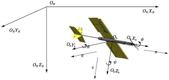
Figure 1.
The motion of the UAAV in a coordinate system.
The UAAV’s kinematic model is given as:
where represents the inertia matrix of the system; denotes the Coriolis and centripetal forces; stands for the control input as well as disturbance forces and torques under interference conditions.
Expressions of and are defined as follows [31]
where for inertia matrix satisfies the symmetry property and is a constant matrix, i.e., , i.e., is a real symmetric constant matrix.
2.2. Controlled Design of the Controller
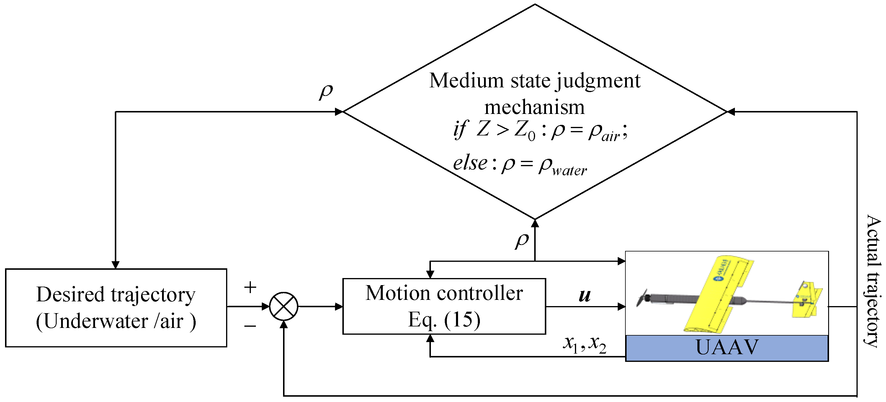
To more intuitively demonstrate the developed control scheme, the entire control architecture is depicted in Figure 2. Considering that the transmedia are mainly concerned with the positional quantities in the longitudinal plane of the UAAV during the water exit, the and are considered to be reasonable. Thus, the kinematic and dynamic model of the UAAV can be simplified to the mathematical model of 4DOF as follows
where is the state variable of the system, i.e., linear and angular displacements in the longitudinal plane in the geodetic coordinate system; is the first-order state variables of the system, i.e., linear and angular velocities in the longitudinal plane of the body coordinate system; is the output of the system indicating the position and attitude state of the UAAV; denotes inputs to the control system; is the inverse of the quality matrix in the control system; is the inverse of the quality matrix in the control system; is the product of the inverse of the mass matrix in the control system and the forces and moments in addition to the control forces and moments.
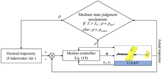
Figure 2.
Schematic of control architecture for the UAAV.
Let be the reference trajectory, then the tracking error can be given as
Considering the following Lyapunov function
Taking the time derivative of as:
According to the design process of the backstepping method, the corresponding virtual control law is designed as follows:
where is a positive constant control parameter, is the virtual control law.
Considering the problem of “explosion of complexity” caused by the derivative of , which is common in backstepping design, a new state variable is developed to obtain the differentiation of by introducing a first-order filter:
Defining virtual control law tracking error as , the time derivative of can be further derived as:
Here, the new Lyapunov function is given as
Taking the time derivative of as:
Here, the kinetic control law is proposed as follows to promote system stability:
where is a positive constant control parameter. satisfies .
Substituting the above controller into the time derivative of , it yields that
where . Apparently, it is verified that the whole control system is able to reach an asymptotically stable state.
3. Propulsion System Experiment and Transmedia Performance Research
To establish the relationship between the underwater and aerial propeller speeds and thrust of the aircraft and to prepare for subsequent motion control simulations of the aircraft, making the simulation more realistic, partial prototype experiments were conducted on the cross-medium aircraft control system. The experiment focused on the thrust of the aerial propeller, which was fixed on a test stand and powered by a lithium battery. The experiment took place in a large indoor water tank with no wind. The PWM controller provided signal values (PWM values). The initial PWM value for the propeller was set at 1000 (corresponding to 1/7 throttle percentage), starting with incremental increases of 100 for each iteration (equivalent to a 1/14 increase in throttle). The PWM value increased to 1700 (corresponding to 9/14 throttle). Simultaneously, the voltage and current readings from the lithium battery, as well as the recorded tension readings, were documented with each increment. The experimental data, including lithium battery voltage, current, and propeller tension, were collected as shown in Table 1. After continuous measurements at the set PWM values, the temperature of the electronic speed controller was recorded, stabilizing at 41 °C over a sustained operational period.

Table 1.
Propeller thrust experiment data.
The underwater propeller thrust experiment was conducted in a water tank where the overall frame was secured to a fixed object at the edge of the tank. The underwater section of the frame immobilized the propeller for underwater operation, allowing for a comprehensive experiment of the propeller underwater. Similar to the propeller experiment in the air, the thrust of the propeller was calculated using a tension meter based on the principles of leverage. This facilitated the measurement of the propeller thrust, aiming to verify whether the propeller could meet the thrust requirements when operating underwater, specifically to fulfill the demands for emerging from the water. In the windless conditions of the indoor ship tank, the propeller was fixed to the frame, and the entire propeller was submerged in the water tank for the experiment. The experiment data of underwater propeller thrust is shown in Table 2.
Table 2.
Underwater propeller thrust experiment data.
The fuselage of the fixed-wing transmedia UAAV is a cylindrical pressure-resistant chamber, and the main wing is directly connected to the fuselage. Considering that the wing may be subjected to large external forces when the UAAV enters or leaves the water, it is decided to adopt the upper monoplane form, and the wing, as a whole, is not disconnected in the center. Buoyant materials are arranged inside the wing to ensure the stability of the UAAV in the water. Before meeting the thrust requirements, a single thruster is used, placed at the forefront of the UAAV, which is convenient to provide thrust at the first time after leaving the water [32]. In order to enhance the stability of navigation and ensure good navigation performance and easy control, the UAAV should be set up with a tail using a combination of horizontal and vertical tails. The end of the wing should also be configured with two ailerons to control the UAAV roll angle to make its navigation process more stable.
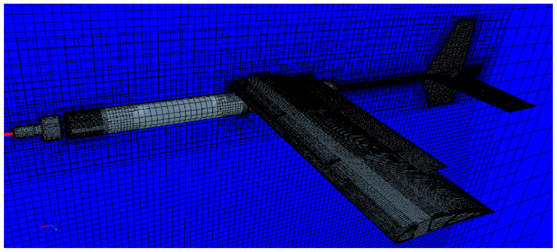
Vehicle emergence is one of the most critical working conditions for the UAAV, and simulation of the emergence process can further explain the performance of the UAAV, identify the design defects of the UAAV, and, thus, optimize its design. The upward initial velocity of the UAAV in the vertical direction is helpful for the emergence process; however, the magnitude of the initial velocity varies depending on the acceleration distance of the UAAV and the underwater propulsion force [33]. Therefore, a certain simplification is made in the preliminary simulation of the emergence state by assuming that the initial velocity is 0, i.e., there is no help to the emergence process in terms of initial velocity, and if this state can successfully emerge from the water, the possibility of the UAAV emergence from the water is higher in real conditions. The grid map of the UAAV in STAR-CCM+ software is shown in Figure 3. We simplify the three-dimensional model of the UAAV as much as possible by deleting the parts and features that have little influence on the hydrodynamic simulation, but we need to ensure that the drainage volume and the buoyancy center of the model remain unchanged, and we keep the permeable holes and try to ensure that the internal permeable structure of the wing remains unchanged.

Figure 3.
Grid map of the UAAV.
The thrust of the propeller in the underwater low-speed stable operation is 117.9 N—take 50% of the value of the thrust as the simulation of the UAAV underwater movement of the propulsive force, set the control propulsion in the UAAV propulsion out of the water to increase to the air in the thrust test of 95% of the maximum value of the thrust test, i.e., 185.1 N; elevator rudder initial angle is 0°, and the maximum adjustment of the rudder angle is ±25°, with the wing drainage cover plate. The initial angle of the elevator is 0°, the maximum adjustment angle is 25°, the starting position of the UAAV is 0 m, and the height of the water surface is 7 m; the results of the initial example section are shown in Figure 4 and Figure 5.
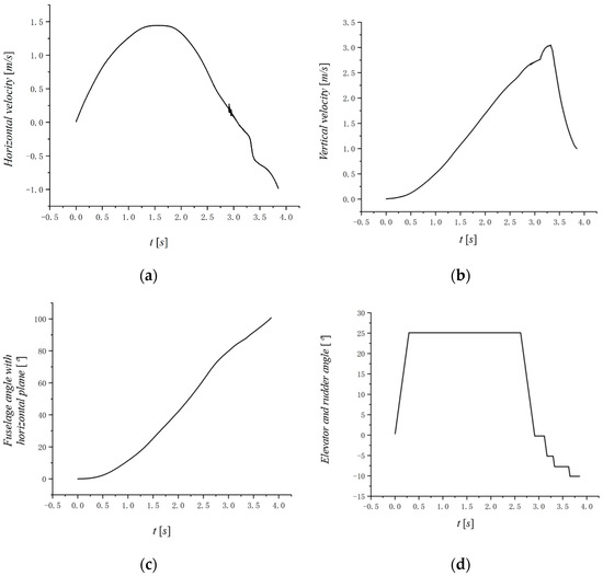
Figure 4.
Simulation result of the UAAV emergence. (a) Horizontal velocity. (b) Vertical velocity. (c) Fuselage angle with horizontal plane. (d) Elevator and rudder angle.
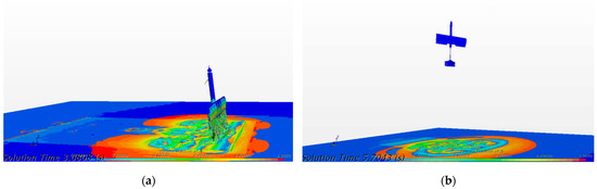
Figure 5.
The image of the UAAV emergence. (a) Image of the moment the vehicle came out of the water. (b) Image of the vehicle fully emerging.
The image of the algorithm running process is shown below:
For the data collected from the fluid simulation of the complete water emergence process of the UAAV, referring to the simulation data and combining it with the debugging process of the simulation algorithms, we can have a more in-depth understanding of the performance of the UAAV, accumulate debugging experience, reduce the cost of trial and error in the future experiments, and provide important references for the subsequent improvement of the motion control system of the UAAV.
4. Simulations
In this section, the designed controllers were applied to the motion control of the UAAV, with the stability improved by incorporating filters. Controllers for the three stages of the UAAV—underwater, airborne, and cross-medium surface—were developed based on this approach. Simulations were performed to validate the motion control of the UAAV in these three stages. Then, the control tasks for the three stages were integrated, and appropriate switching rules for the controllers were developed. This integration successfully achieved comprehensive motion control of the UAAV, including underwater gliding, cross-medium surfacing, and aerial flight.
4.1. Simulation Results of Underwater Motion Control
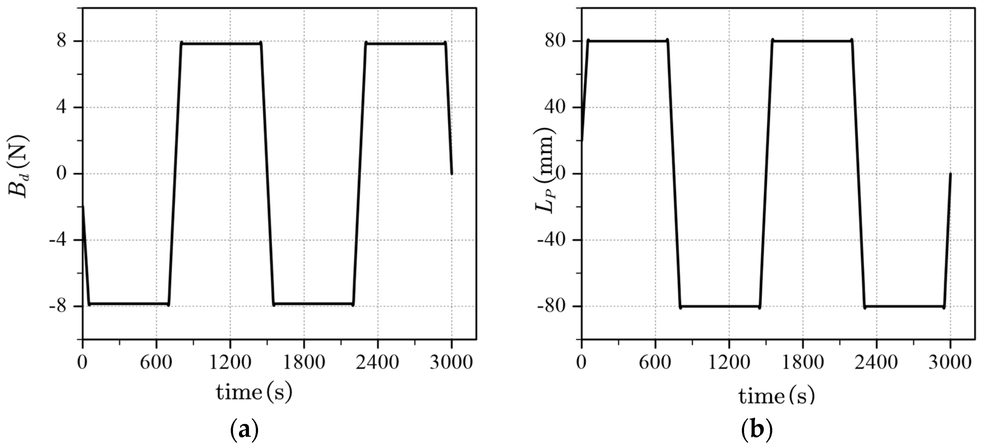
The UAAV propels its zigzag motion by adjusting its buoyancy. The weight of the battery pack responsible for adjusting the UAAV’s center of gravity is 1300 g, with a maximum displacement of 0.08 m. The volume of the buoyancy adjustment pump is 800 mL, which can provide a maximum driving buoyancy of 7.84. The UAAV was simulated to perform two zigzag motions within the entire cross section, each lasting 1500 s underwater. The initial motion parameters for the underwater gliding of the UAAV are set as follows
The initial assignment of very small axial velocity in the simulation parameters is aimed at preventing singular values in the numerical solution of the UAAV mathematical model. Based on the above settings, the control simulation results of the underwater motion of the UAAV were obtained. In these simulations, the driving buoyancy and the pitch adjustment of the battery pack serve as the driving inputs for the underwater gliding motion of the UAAV along the axis. Under these initial conditions, the relationship between the control inputs (horizontal movement of the driving buoyancy and pitch adjustment of the battery pack) and the time during the underwater gliding motion of the UAAV is shown in Figure 6. The simulation results of the “zigzag” motion control of the UAAV during underwater gliding are shown in Figure 7.

Figure 6.
Time responses of control inputs. (a) Driving buoyancy. (b) Center of gravity adjustment distance.
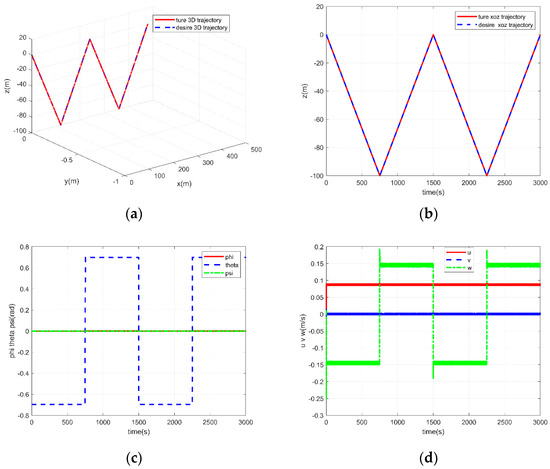
Figure 7.
Simulation result of zigzag motion control. (a) “Zigzag” motion 3D trajectory. (b) The relationship between vehicle depth and simulation time. (c) Vehicle angle with time. (d) Vehicle speed as a function of time.
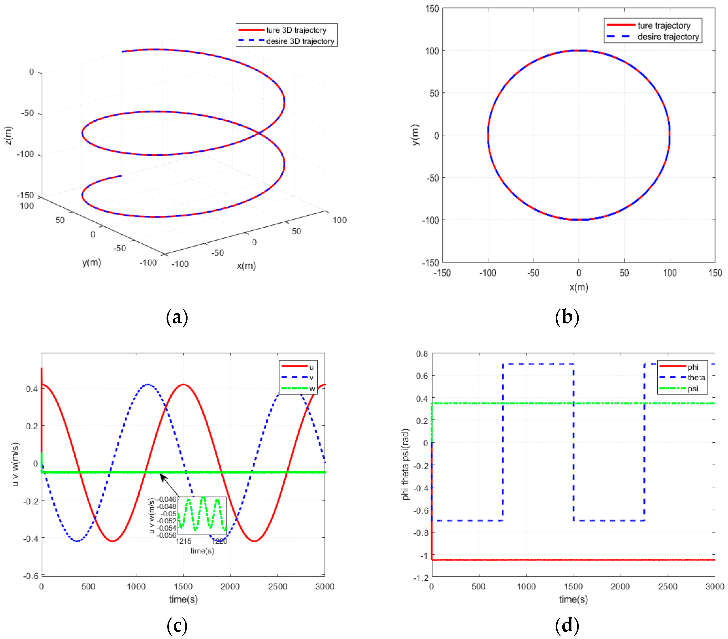
A simulation of spiral dive motion during underwater gliding of the UAAV was performed. The spiral dive motion during the UAAV’s underwater glide plays a crucial role in changing the glide direction. Based on the “zigzag” motion described above, a special rolling mechanism is added to the battery pack to control the spiral dive of the UAAV. The total simulation time is set to 3000 s, with the driving buoyancy and pitch adjustment following the same pattern as the ‘zigzag’ simulation. The simulation parameters remain unchanged throughout the process. The simulation results of the spiral dive motion are shown in Figure 7.
Figure 8 illustrates the stable turning motion of the UAAV. The results in Figure 8a,b show that the UAAV achieves a stable turning motion with a radius of 150 m, a cycle time of 1500 s, and a diving depth of 150 m. Figure 8c,d shows the relationship between the speed and attitude of the UAAV during the diving process with respect to the simulation time. The results show the average dive velocity of the UAAV, calculated as 0.05 units, and the periodic variation of the glide angle over time.
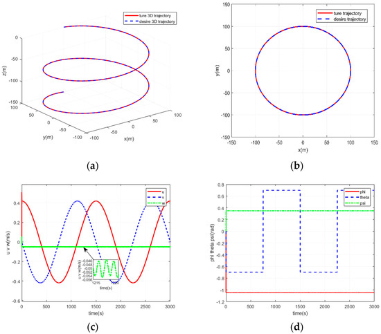
Figure 8.
Simulation results of the UAAV’s spiral diving motion. (a) Spiral dive three-dimensional space trajectory. (b) The projection of the spatial trajectory in the horizontal plane. (c) The relationship between speed and simulation time. (d) The relationship between attitude and simulation time. The black arrow denotes a local magnification of the w curve.
4.2. Simulation Results of Aerial Motion Control
The airborne motion of the UAAV is primarily focused on high angle of attack simulations after surfacing. In this phase, control is achieved by coordinating the UAAV’s airscrews as propulsion mechanisms and manipulation devices such as horizontal rudders and directional flaps.
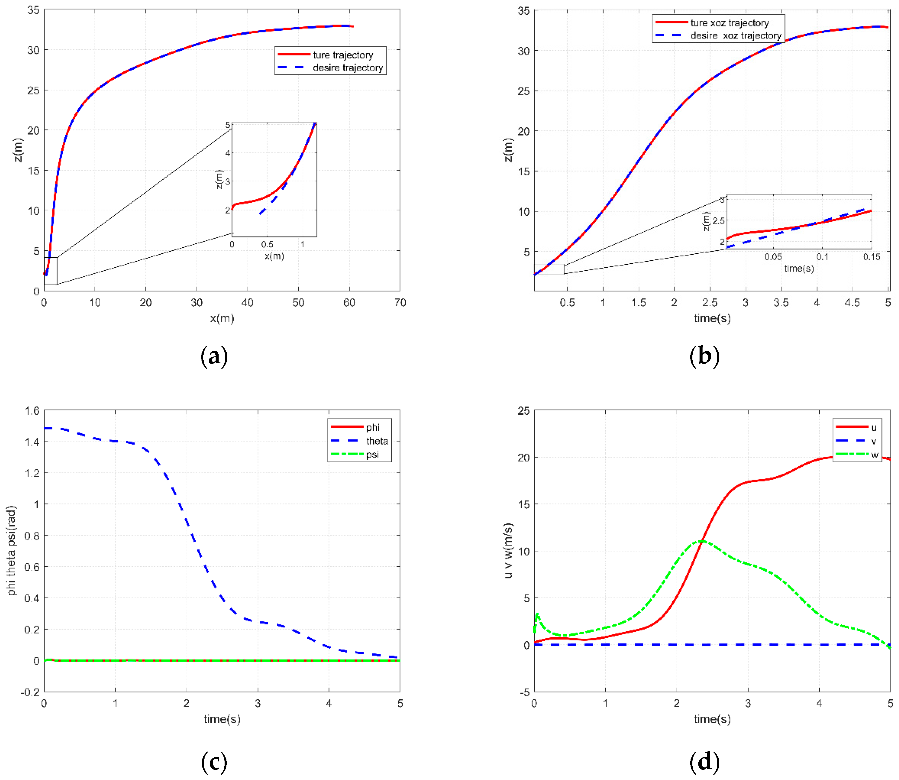
During aerial motion, the UAAV experiences a process where, after a high-angle launch from the water, it enters a high-angle-of-attack state. In this state, the lift provided by the body and wings is limited, requiring precise coordination between the propulsion system and the control devices. Rapid adjustments to the UAAV’s pitch angle are made to achieve stable-level flight. The dynamic model considers forces primarily from aerodynamics, control forces (including propulsion from the propulsion system and control forces from the manipulation system), and disturbance forces. The initial parameters for the aerial simulation state are set as ; ; ; ; ; ; ; . The controller parameters for the aerial phase are configured accordingly. Simulations conducted within a 5 s timeframe yielded the UAAV’s aerial motion results shown in Figure 9, along with corresponding responses from the propulsion and manipulation systems depicted in Figure 10.
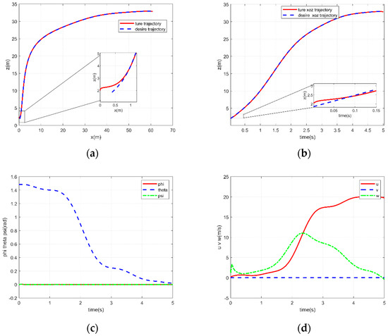
Figure 9.
Time responses of the UAAV altitude during aerial motion simulation. (a) z-x trajectory of the vehicle’s air motion. (b) Variation of the altitude of the vehicle with respect to time. (c) Euler angle changes with time. (d) Velocity as a function of time.
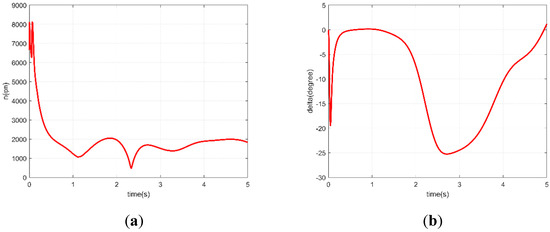
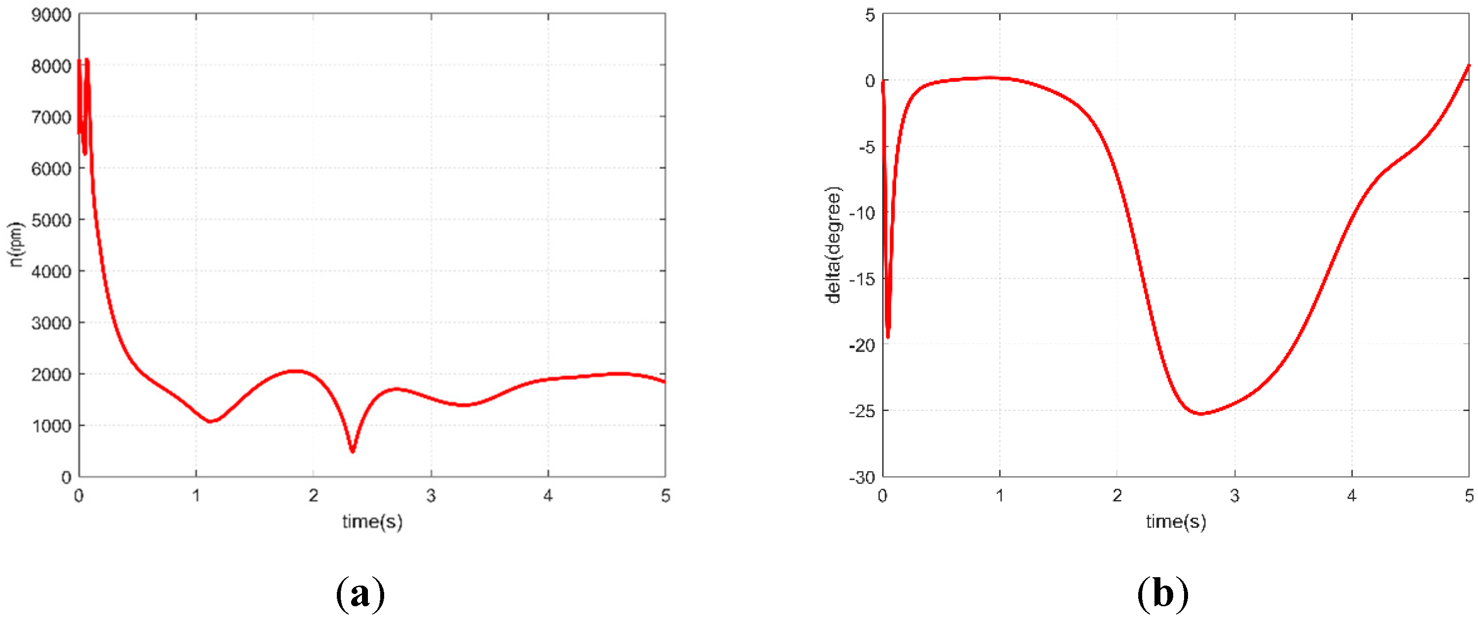
Figure 10.
Time responses of propulsion and control systems during aircraft aerial motion. (a) The change of propeller speed with time as red color curve. (b) The relationship of rudder angle with time as red color curve.
The results shown in Figure 9 indicate that the airplane can successfully follow the target trajectory during its flight. The pitch angle stabilizes to a level flight state at about 3 s, as shown in Figure 9d, corresponding to the axial and vertical velocities during the process. The results shown in Figure 10 reflect the responses of the main propulsion system and the control system over time during the aircraft’s flight movement, confirming that both systems meet the requirements for the aircraft’s high angle of departure during the flight phase.
4.3. Simulation Results of Cross-Medium Environment
During the cross-media phase, the UAAV operates in a cross-media environment and experiences different media states, including both air and water. In this phase, the motion control of the UAAV is studied by considering a simplified model consisting of a cylindrical body and rectangular wings. In this simplified scenario, the UAAV experiences forces from the water, including inertial forces, viscous forces, and control moments generated by underwater rudders. In the air, the UAAV is controlled by the rotating propellers. By simplifying the UAAV dynamics model during the cross-medium phase, the dynamics of the UAAV during the water exit phase can be effectively modeled [34,35].
Note: For the motion during moving in and out of media, the model is unchanging. But considering the resistance difference between seawater and air, the control forces need to be changed. Specifically, users can select the appropriate control parameters and to guarantee the system stability to obtain favorable control performance. By selecting the appropriate control parameters and , the control forces can be adjusted adequately to satisfy the need for control performance in cross-media environments. After selecting the appropriate control parameters and , the obtained control signals are properly distributed to the UAAV’s stern rudder and propeller to produce corresponding thrust and control torque such that the UAAV can track the preset desired trajectory under the proposed backstepping-based control scheme.
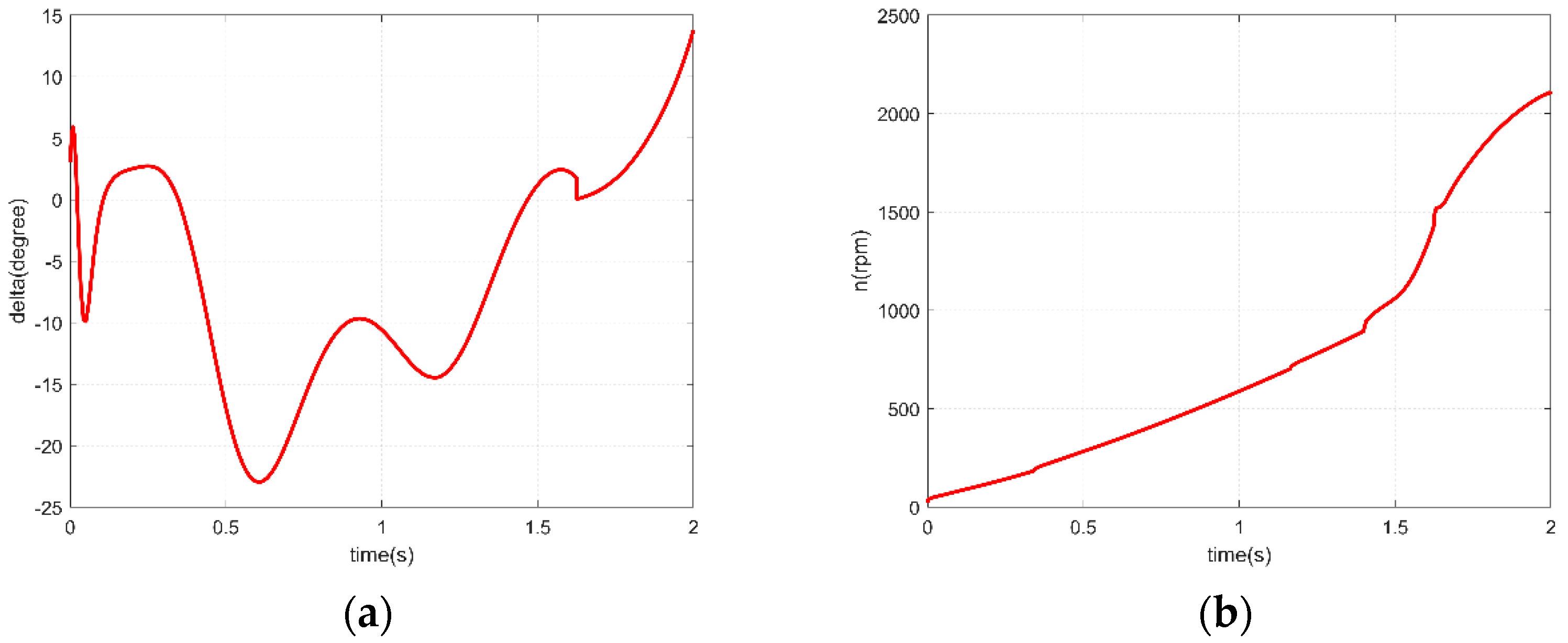
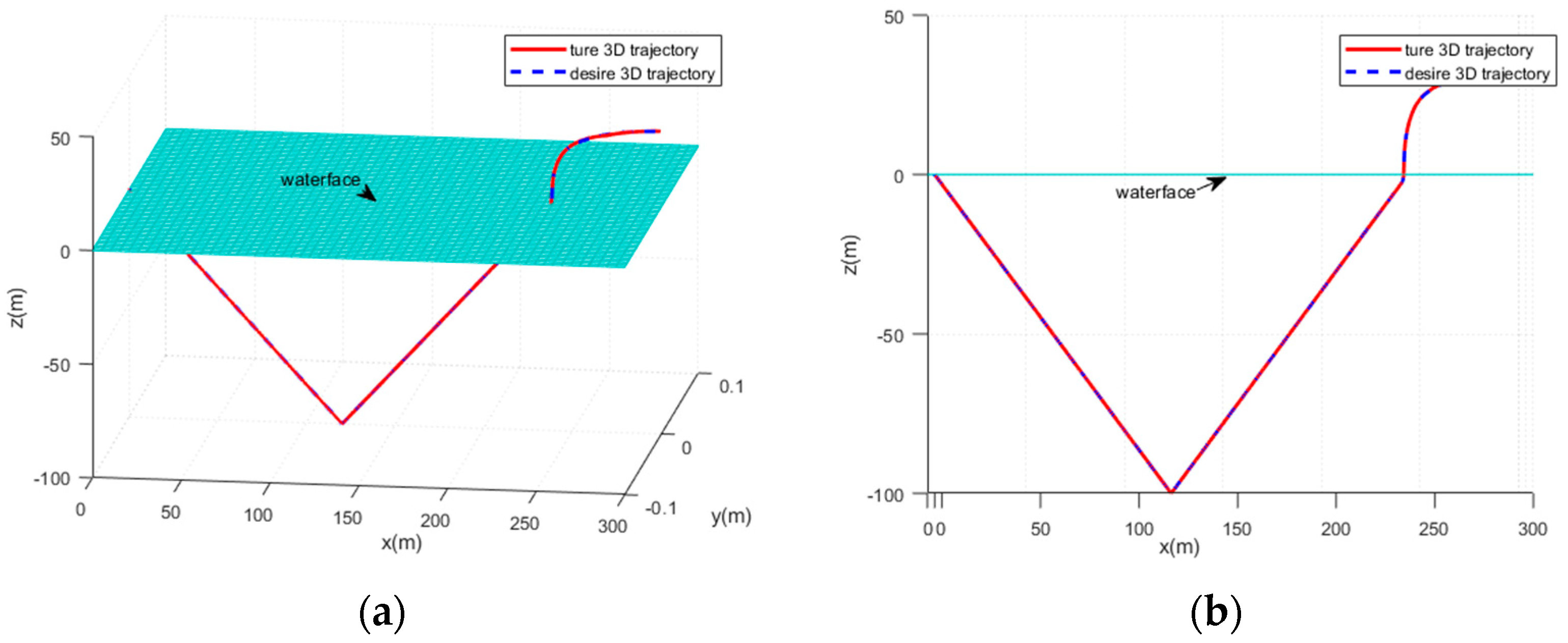
The specific simulation parameters are as follows: initial state parameters are ; ; ; ; ; ; ; . The controller parameters were adjusted to find the most suitable parameters for the water exit process, i.e., ; . The simulation results of the UAAV during the cross-medium water exit phase are shown in Figure 11, and the simulation results of the response of the propulsion and control systems are depicted in Figure 12.
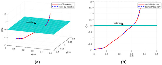
Figure 11.
Simulation results during the cross-medium phase. (a) Vehicle exit phase trajectory. (b) Projection of the water trajectory on the x-o-z plane.
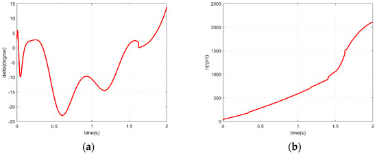
Figure 12.
Control system responses at the water ejection stage. (a) Stern rudder response curve. (b) Propeller response curve.
The results shown in Figure 11 reflect that the UAAV can follow the target trajectory during the water ejection process. The UAAV completes the water ejection in about 1.3 s, as shown by the propeller response curve in Figure 10b, where the propeller speed rapidly increases after the ejection, “pulling” the UAAV out of the water surface. The simulation results in Figure 10 illustrate the time response of the main propulsion system and the control system during the water ejection process.
4.4. Simulation Results of Complete Mission Phase of the UAAV
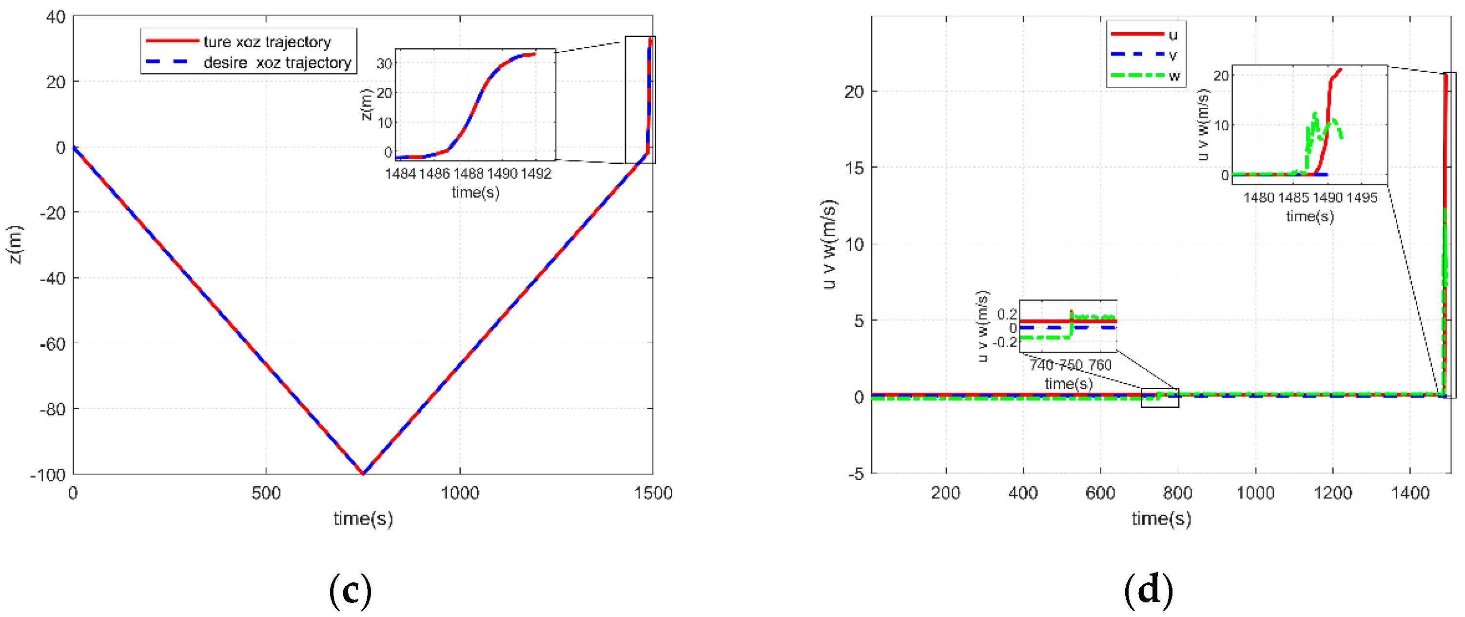
The watercraft integrates these three stages and undergoes control simulation throughout the mission phase, achieving the design objective of enabling the amphibious UAAV to move across media in both water and air. The control parameters of the watercraft vary according to the medium it is in, and the simulation trajectories are designed for the underwater, cross-medium, and air phases. The initial state represents the phase when the watercraft is ready for underwater gliding, followed by 1462.5 s of underwater gliding, and then the transition to the phase of surfacing and taking off at a high angle. The simulated results of the watercraft are shown in Figure 13, and the corresponding responses of the control system are shown in Figure 14.

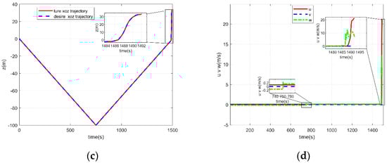
Figure 13.
Simulation results of the amphibious UAAV in cross-medium navigation. (a) Three-dimensional trajectory tracking diagram of the overall motion process. (b) Projection of the trajectory on the x-o-z plane. (c) The relationship between height and time. (d) Velocity as a function of time.
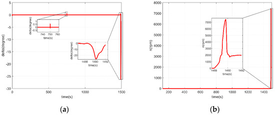
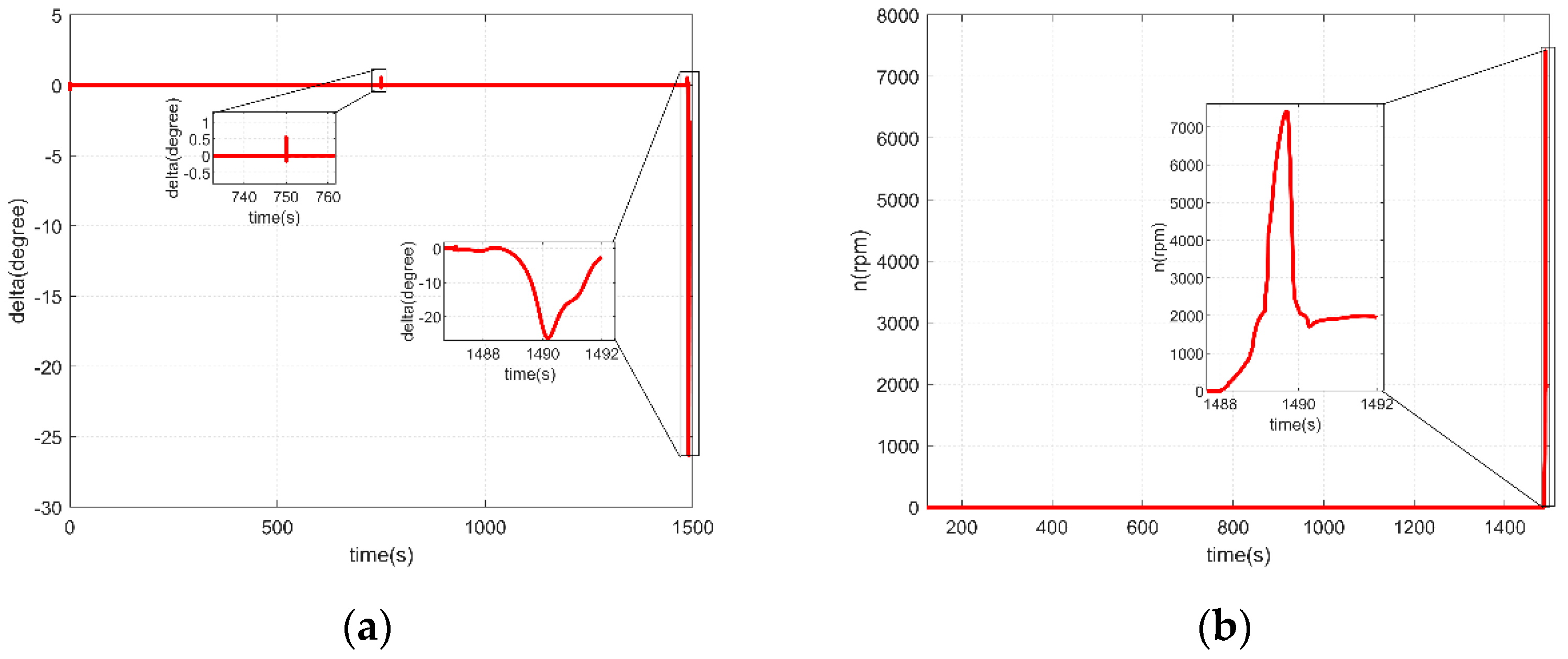
Figure 14.
Responses of the control actuators of the amphibious UAAV. (a) Rudder angle response throughout the mission as the red color curve. (b) Propeller response throughout the mission as the red color curve.
The results of the above simulation experiments show that the designed improved backstepping controller can successfully navigate the amphibious UAAV throughout the entire cross-medium mission process. First, as shown in Figure 13a,b, the simulation results reflect the controller’s ability to track the predefined target trajectory along with the corresponding linear velocities in three directions as shown in Figure 13d. The control inputs during this process include the thrust from the propellers and the responses of the control systems, as shown in Figure 14. Compared with the control methods proposed in the existing literature, this paper conducts a simulation analysis of the motion characteristics of the UAAV. Subsequently, through the design of a cross-medium vehicle’s motion control simulations in underwater, aerial, and cross-medium surfacing phases, the designed controller’s capability to achieve target trajectory tracking is validated. Simultaneously, the corresponding response of the control system meets practical requirements. The control tasks of the three phases are then integrated, and the switching rules for the controller are reasonably designed. This integration realizes the overall motion control of the cross-medium vehicle through three mission phases: underwater gliding, cross-medium surfacing, and aerial flight. The performance of the cross-medium vehicle’s motion controller in attitude control and trajectory tracking is verified to be excellent.
5. Conclusions
This paper provides a design of a motion controller based on the improved backstepping method for the nonlinear control problems encountered in the control of UAAVs and the control objects to cross two different media. This design applies the nonlinear control method to the motion control of UAAVs and adds filters to increase the stability of control. The integration of stability-boosting filters further fortifies the designed controller, ensuring its resilience in real-world scenarios. The meticulous design of the motion controller tailored for the distinct phases of UAAV operation signifies a significant stride in the realm of autonomous vehicle control systems. A noteworthy contribution of this research lies in the successful integration of control tasks across the three phases of UAAV operation. The carefully devised switching rules enable the motion controller to seamlessly orchestrate the entire spectrum of the UAAV’s motion, encompassing underwater gliding, transmedia surfacing, and aerial flight. This holistic approach not only underscores the versatility of the controller but also positions it as a pivotal component in achieving comprehensive autonomy for UAAVs. In summary, this research not only introduces an effective motion controller for UAAV but also substantiates its reliability and adaptability through rigorous simulation testing. The demonstrated robustness, precision, and versatility of the motion controller contribute significantly to the evolving field of UAAV control systems, paving the way for enhanced autonomy and operational efficiency in diverse environments.
This research was constrained by experimental conditions, and there are still many issues worth exploring. Future research on the motion control of cross-medium vehicles can improve and expand the following aspects:
- (1)
- Accurate analysis and optimization of the dynamical characteristics of the vehicle: In this paper, significant simplifications were made in modeling the motion control of the vehicle, primarily focusing on control simulations. Nonlinearities, strong couplings, and time-varying parameters, especially during crossmedium transitions, were only considered on a simplified basis, resulting in a certain gap from real-world scenarios. Subsequent efforts should involve a more extensive analysis of the vehicle’s dynamical characteristics to establish a more accurate dynamical model.
- (2)
- Optimization and refinement of the tuning of vehicle control algorithms and parameters: The research in this paper primarily resides in theoretical simulation. Future work should involve applying the proposed control algorithms to real crossmedium vehicles, validating the performance of the control methods in actual environments.
- (3)
- Utilization of formal verification and validation techniques to enhance the quality and ensure the correctness of Internet of Things (IoT) services [36,37].
Author Contributions
X.S., W.W. and H.L. contributed to conceptualization, methodology, formal analysis and writing—original draft preparation; J.C. and Y.L. contributed to supervision, project administration and funding acquisition. All authors have read and agreed to the published version of the manuscript.
Funding
The research was co-supported by the Hainan Provincial Joint Project of Sanya Yazhou Bay Science and Technology City, Grant No: 520LH007; the work was financially supported by the National Natural Science Foundation of China (52071104); the project was supported by the Stable Supporting Fund of Science and Technology on Underwater Vehicle Technology (JCKYS2023SXJQR-02) and National Key R&D Program of China (2021YFC2800500).
Institutional Review Board Statement
Not applicable.
Informed Consent Statement
Not applicable.
Data Availability Statement
Due to privacy, the data is unavailable. The data that support the findings of this study are available on request from the corresponding author. The data are not publicly available due to privacy or ethical restrictions.
Conflicts of Interest
The authors declare no conflict of interest.
References
- Coe, R.G. Improved Underwater Vehicle Control and Maneuvering Analysis with Computational Fluid Dynamics Simulations. Ph.D. Thesis, Virginia Tech, Blacksburg, VA, USA, 2013. [Google Scholar]
- Eisenbeiss, H. A mini unmanned aerial vehicle (UAV): System overview and image acquisition. In Proceedings of the International Archives of Photogrammetry, Remote Sensing and Spatial Information Sciences, Pitsanulok, Thailand, 18–20 November 2004; Volume 36, pp. 1–7. [Google Scholar]
- Li, G.; Zhang, H.; Tang, G. Maneuver characteristics analysis for hypersonic glide vehicles. Aerosp. Sci. Technol. 2015, 43, 321–328. [Google Scholar] [CrossRef]
- Shen, C. Motion Control of Autonomous Underwater Vehicles Using Advanced Model Predictive Control Strategy. Ph.D. Thesis, University of Victoria, Victoria, BC, Canada, 2018. [Google Scholar]
- Moore, J.; Fein, A.; Setzler, W. Design and analysis of a fixed-wing unmanned aerial-aquatic vehicle. In Proceedings of the 2018 IEEE International Conference on Robotics and Automation (ICRA), Brisbane, Australia, 21–25 May 2018; pp. 1236–1243. [Google Scholar]
- Sánchez-García, J.; García-Campos, J.; Arzamendia, M.; Reina, D.; Toral, S.; Gregor, D. A survey on unmanned aerial and aquatic vehicle multi-hop networks: Wireless communications, evaluation tools and applications. Comput. Commun. 2018, 119, 43–65. [Google Scholar] [CrossRef]
- Alzu’bi, H.; Mansour, I.; Rawashdeh, O. Loon copter: Implementation of a hybrid unmanned aquatic–aerial quadcopter with active buoyancy control. J. Field Robot. 2018, 35, 764–778. [Google Scholar] [CrossRef]
- Ravell, D.A.; Maia, M.M.; Diez, F.J. Modeling and control of unmanned aerial/underwater vehicles using hybrid control. Control Eng. Pract. 2018, 76, 112–122. [Google Scholar] [CrossRef]
- Neto, A.A.; Mozelli, L.A.; Drews, P.L.; Campos, M.F. Attitude Control for an Hybrid Unmanned Aerial Underwater Vehicle. In Proceedings of the IEEE International Conference on Robotics and Automation, Seattle, WA, USA, 26–30 May 2015; Volume 10, pp. 78–81. [Google Scholar]
- Yang, J.; Li, Y.; Feng, J.; Hu, J.; Liu, A. Simulation and experimental research on trans-media vehicle water-entry motion characteristics at low speed. PLoS ONE 2015, 12, e0178461. [Google Scholar] [CrossRef] [PubMed]
- Lu, D.; Xiong, C.; Zeng, Z.; Lian, L. A Multimodal Aerial Underwater Vehicle with Extended Endurance and Capabilities. In Proceedings of the International Conference on Robotics and Automation (ICRA), Montreal, QC, Canada, 20–24 May 2019; pp. 4674–4680. [Google Scholar]
- Wu, Y.; Li, L.; Su, X.; Gao, B. Dynamics modeling and trajectory optimization for unmanned aerial-aquatic vehicle diving into the water. Aerosp. Sci. Technol. 2019, 89, 220–229. [Google Scholar] [CrossRef]
- Wu, Y. Coordinated path planning for an unmanned aerial-aquatic vehicle (UAAV) and an autonomous underwater vehicle (AUV) in an underwater target strike mission. Ocean Eng. 2019, 182, 162–173. [Google Scholar] [CrossRef]
- Huang, B.; Zhou, B.; Zhang, S.; Zhu, C. Adaptive prescribed performance tracking control for underactuated autonomous underwater vehicles with input quantization. Ocean Eng. 2021, 221, 108549. [Google Scholar] [CrossRef]
- Huang, B.; Song, S.; Zhu, C.; Li, J.; Zhou, B. Finite-time distributed formation control for multiple unmanned surface vehicles with input saturation. Ocean Eng. 2021, 233, 109158. [Google Scholar] [CrossRef]
- Huang, B.; Zhang, S.; He, Y.; Wang, B.; Deng, Z. Finite-time anti-saturation control for Euler–Lagrange systems with actuator failures. ISA Trans. 2022, 124, 468–477. [Google Scholar] [CrossRef]
- Zhou, B.; Huang, B.; Su, Y.; Wang, W.; Zhang, E. Two-layer leader-follower optimal affine formation maneuver control for networked unmanned surface vessels with input saturations. Int. J. Robust Nonlinear Control 2023, 1–25. [Google Scholar] [CrossRef]
- Ma, Z.; Feng, J.; Yang, J. Research on vertical air–water trans-media control of Hybrid Unmanned Aerial Underwater Vehicles based on adaptive sliding mode dynamical surface control. Int. J. Adv. Robot. Syst. 2015, 18, 96–101. [Google Scholar] [CrossRef]
- da Rosa, R.T.; Evald, P.J.; Drews, P.L.; Neto, A.A.; Horn, A.C.; Azzolin, R.Z.; Botelho, S.S. A Comparative Study on Sigma-Point Kalman Filters for Trajectory Estimation of Hybrid Aerial-Aquatic Vehicles. In Proceedings of the IEEE/RSJ International Conference on Intelligent Robots and Systems (IROS), Madrid, Spain, 1–5 October 2018; pp. 7460–7465. [Google Scholar]
- Lu, D.; Xiong, C.; Zeng, Z.; Lian, L. Adaptive dynamic surface control for a hybrid aerial underwater vehicle with parametric dynamics and uncertainties. IEEE J. Ocean. Eng. 2019, 45, 740–758. [Google Scholar] [CrossRef]
- Lu, D.; Xiong, C.; Lyu, B.; Zeng, Z.; Lian, L. Multi-mode hybrid aerial underwater vehicle with extended endurance. In Proceedings of the 2018 OCEANS-MTS/IEEE Kobe Techno-Oceans (OTO), Kobe, Japan, 28–31 May 2018; pp. 1–7. [Google Scholar]
- Siddall, R.; Kovač, M. Launching the AquaMAV: Bioinspired design for aerial–aquatic robotic platforms. Bioinspir. Biomim. 2014, 9, 031001. [Google Scholar] [CrossRef] [PubMed]
- Durán-Delfín, J.; García-Beltrán, C.; Guerrero-Sánchez, M.; Valencia-Palomo, G.; Hernández-González, O. Modeling and Passivity-Based Control for a convertible fixed-wing VTOL. Appl. Math. Comput. 2024, 461, 128298. [Google Scholar] [CrossRef]
- Stewart, W.; Weisler, W.; MacLeod, M.; Powers, T.; Defreitas, A.; Gritter, R.; Anderson, M.; Peters, K.; Gopalarathnam, A.; Bryant, M. Design and demonstration of a seabird-inspired fixed-wing hybrid UAV-UUV system. Bioinspir. Biomim. 2018, 13, 27–31. [Google Scholar] [CrossRef]
- SNAME. Nomenclature for Treating the Motion of a Submerged Body through a Fluid; SNAME Technical and Research Bulletin; Society of Naval Architects and Marine Engineers: Jersey City, NJ, USA, 1950. [Google Scholar]
- Bannwarth, J.X.; Chen, Z.J.; Stol, K.A.; MacDonald, B.A. Disturbance accomodation control for wind rejection of a quadcopter. In Proceedings of the International Conference on Unmanned Aircraft Systems, Arlington, VA, USA, 7–10 June 2016; pp. 695–701. [Google Scholar]
- Izraelevitz, J.S.; Triantafyllou, M.S. A novel degree of freedom in flapping wings shows promise for a dual aerial/aquatic vehicle propulsor. In Proceedings of the 2015 IEEE International Conference on Robotics and Automation (ICRA), Seattle, WA, USA, 26–30 May 2015; pp. 5830–5837. [Google Scholar]
- Liang, J.; Yang, X.; Wang, T.; Yao, G.; Zhao, W. Design and Experiment of a Bionic Gannet for Plunge-Diving. J. Bionic Eng. 2013, 10, 282–291. [Google Scholar] [CrossRef]
- Gao, A.; Techet, A.H. Design considerations for a robotic flying fish. In Proceedings of the OCEANS’11 MTS/IEEE KONA, Waikoloa, HI, USA, 19–22 September 2011; pp. 1–8. [Google Scholar]
- Weisler, W.; Stewart, W.; Anderson, M.B.; Peters, K.J.; Gopalarathnam, A.; Bryant, M. Testing and Characterization of a Fixed Wing Cross-Domain Unmanned Vehicle Operating in Aerial and Underwater Environments. Ocean. Eng. IEEE J. 2018, 43, 969–982. [Google Scholar] [CrossRef]
- Yang, X.; Wang, T.; Liang, J.; Yao, G.; Zhao, W. Submersible unmanned aerial vehicle concept design study. In Proceedings of the Aviation Technology Integration and Operations Conference, Los Angeles, CA, USA, 12–14 August 2013; pp. 1–12. [Google Scholar]
- Moore, J. Closed-Loop Control of a Delta-Wing Unmanned Aerial-Aquatic Vehicle. arXiv 2019, arXiv:1906.01532. [Google Scholar]
- Stewart, W.; Weisler, W.; Anderson, M.; Bryant, M.; Peters, K. Dynamic modeling of passively draining structures for aerial–aquatic unmanned vehicles. IEEE J. Ocean. Eng. 2019, 45, 840–850. [Google Scholar] [CrossRef]
- Fengbo, Y.; Xinyu, X.; Ling, Z.; Zhu, S. Numerical simulation and experimental verification on downwash air flow of six-rotor agricultural unmanned aerial vehicle in hover. Int. J. Agric. Biol. Eng. 2017, 10, 41–53. [Google Scholar] [CrossRef]
- Hwang, J.Y.; Jung, M.K.; Kwon, O.J. Numerical study of aerodynamic performance of a multirotor unmanned-aerial-vehicle configuration. J. Aircr. 2015, 52, 839–846. [Google Scholar] [CrossRef]
- Krichen, M. A Survey on Formal Verification and Validation Techniques for Internet of Things. Appl. Sci. 2023, 13, 8122. [Google Scholar] [CrossRef]
- Hofer-Schmitz, K.; Stojanović, B. Towards formal verification of IoT protocols: A Review. Comput. Netw. 2020, 174, 107233. [Google Scholar] [CrossRef]


Disclaimer/Publisher’s Note: The statements, opinions and data contained in all publications are solely those of the individual author(s) and contributor(s) and not of MDPI and/or the editor(s). MDPI and/or the editor(s) disclaim responsibility for any injury to people or property resulting from any ideas, methods, instructions or products referred to in the content. |
© 2023 by the authors. Licensee MDPI, Basel, Switzerland. This article is an open access article distributed under the terms and conditions of the Creative Commons Attribution (CC BY) license (https://creativecommons.org/licenses/by/4.0/).