Article

Underwater Line Monitoring Using Optimally Placed Inclinometers

by
Chungkuk Jin
1,* and
Seong Hyeon Hong
2,*
1
Department of Ocean Engineering and Marine Sciences, Florida Institute of Technology, Melbourne, FL 32901, USA
2
Department of Mechanical and Civil Engineering, Florida Institute of Technology, Melbourne, FL 32901, USA
*
Authors to whom correspondence should be addressed.
J. Mar. Sci. Eng. 2024, 12(11), 1939; https://doi.org/10.3390/jmse12111939
Submission received: 14 September 2024 / Revised: 24 October 2024 / Accepted: 27 October 2024 / Published: 29 October 2024
(This article belongs to the Special Issue Structural Analysis and Failure Prevention in Offshore Engineering)

Abstract

:
Underwater monitoring presents challenges related to maintaining a continuous power supply and communication, necessitating the use of a smaller number of sensors to effectively cover the entire line. An underwater line tracking method is proposed to evaluate global behaviors and stresses in real time. The method employs angles at several points on the line, as well as displacements and curvatures at both ends. In this method, any line displacement, angle, and curvature are expressed as Fourier series, and Fourier coefficients are obtained by utilizing sensor data. Then, the behavior of any line location is assessed. In addition, to reduce the number of sensors and improve accuracy, optimal inclinometer locations are determined by a genetic algorithm. The proposed line tracking algorithm was validated through two numerical examples; one with an inclined tunnel and one with a marine steel catenary riser attached to a Floating Production Storage and Offloading (FPSO) vessel. Through these examples, the proposed algorithm was proven to capture global behaviors accurately when optimally located sensors are used. In the riser monitoring case, the optimized sensor placement with eight intermediate sensors achieved an average mean distance error of 1.91 m, which is lower than the 2.65 m error obtained with ten intermediate sensors without optimization.

1. Introduction

Underwater monitoring is challenging in nature due to problems associated with continuous power supply and communication. In particular, monitoring long, slender, flexible line-like structures—such as risers, mooring lines, and underwater pipelines—presents significant challenges due to long-range surveillance. While remotely operated vehicles (ROVs), autonomous underwater vehicles (AUVs), and underwater robots have been used for various tasks, their primary function remains limited to visual surveys [1,2,3]. The application of visual inspection is generally restricted to tasks such as detecting cracks and holes. Moreover, their operations are often costly, and real-time monitoring is frequently infeasible. Another method involves using monitoring sensors, which offer a cost-effective solution and enable real-time transmission of data to the surface platform. Additionally, these sensors provide essential data for estimating accumulated fatigue damage. The sensor-based approach is also crucial for the digitalization and automation of unmanned platforms in offshore environments.
Various types of sensors and algorithms have been employed for monitoring underwater behavior and stresses [4,5,6,7,8,9,10,11,12,13,14,15,16,17,18,19,20,21,22,23,24,25]. To monitor the global behavior and stresses of underwater line-like structures such as risers, various sensors have been employed, including accelerometers, inclinometers, angular rate sensors, and strain gauges. Using these sensors, different monitoring algorithms have also been explored. For example, the mode matching method has been suggested, which identifies dominant excitation modes and estimates fatigue damage along the entire riser [4,5,6]. It involves comparing measured acceleration amplitudes from accelerometers with modal amplitudes obtained from the riser’s finite element (FE) model at various measurement points. This method additionally uses angular rate sensors alongside accelerometers to enhance monitoring accuracy [7]. Moreover, a method similar to the mode matching method, based on the Fourier series, was suggested [8]. This Fourier-series-based method is more generic compared to the mode matching method because it does not rely on any mode shapes. This advantage is particularly significant in marine environments, where obtaining accurate mode shapes for complex structures can be challenging. Researchers also suggested the transfer function method to obtain the power spectral density of the bending moment along the riser by using predefined transfer functions and power spectral density of measured accelerations [9,10,11]. Ge, Kannala, Li, Maheshwari and Campbell [12] proposed an analytical transfer function, derived from beam theory, to convert accelerations to bending moments, which allows for the estimation of the bending moment at the sensor location. Mercan, Chandra, Maheshwari and Campbell [13] conducted a comprehensive comparison of these methods for monitoring drilling risers. Furthermore, inclinometers have been utilized for riser monitoring [14,15]. The algorithm employs polynomial equations defined between two neighboring sensors with coefficients of the polynomial equations from sensor data. Unlike methods using accelerometers and angular rate sensors, the inclinometer-based method does not require time integrations, thereby facilitating more straightforward real-time monitoring.
This study proposes a novel line monitoring method that uses Fourier series with inclinometer measurements. Compared to existing methods that utilize the Fourier series [8] or inclinometers [14,15], the proposed method offers enhanced features. Traditional Fourier series methods rely on accelerometers, which necessitate time derivatives and consequently require Fourier transforms. This process makes real-time monitoring challenging because accurate Fourier transforms require data from a long period. In contrast, the proposed method, which is based on displacement, inclination, and curvature data, eliminates the need for time derivatives and Fourier transforms. As a result, it allows for the continuous calculation of unique Fourier coefficients at each time step, enabling real-time monitoring. Current ocean technology is advancing towards unmanned platforms and structures. In this context, real-time monitoring significantly enhances confidence in structural integrity. The proposed methodology plays a crucial role in achieving this goal. Previous methods using inclinometers depend on polynomial equations (typically 2nd- or 3rd-order) to define the displacement field between sensors. These methods assume that curvature, which is the second derivative of displacement, is linear; therefore, accuracy is guaranteed in the regions near the midpoint between sensors. As a result, the accuracy of bending moment measurements diminishes if sensor intervals are large. In contrast, the Fourier series offers continuous functions not only for displacements but also for angles and curvatures, allowing for more accurate and reliable bending moment estimation. Reliable monitoring of stress and accumulated fatigue damage is critical for life extension, thereby reducing both capital and operational expenditure. The proposed method, therefore, addresses the demerits of traditional methods in monitoring real-time global behavior and stress. The proposed methodology is generic and can be applied to most line-like structures, including risers, marine cables and pipelines, underwater tunnels, submerged floating tunnels, and floating bridges.
The proposed method does have an inherent limitation in that many sensors are required to guarantee a long Fourier series fit to the actual displacement. However, considering the challenging ocean environment, installing many monitoring sensors is not economical. Therefore, optimization was conducted to select the best sensor locations to maximize the performance of line monitoring. Optimizing sensor locations is essential because a uniform distribution of sensors may not provide the highest estimation accuracy for line displacement. This is because the motion of the line may not be most active at the uniformly placed locations. For this reason, a smaller number of sensors placed at optimized locations may outperform a larger number of equally distributed sensors when monitoring line behavior. The details of the proposed method and the case studies are presented in the following section.
The paper is organized into four sections. Section 2 presents the details of the proposed monitoring algorithm. In Section 3, two case studies, focusing on an underwater inclined tunnel and a steel catenary riser, are discussed along with the corresponding numerical models and results. Section 4 concludes the paper by outlining the key findings, limitations, and future research directions.

2. Method

2.1. Line Monitoring Method

The proposed method is based on the approach developed by Mukundan, Hover and Triantafyllou [8]. Their method, which was applied to the vertical riser, is briefly summarized. A line’s displacement can be represented by a combination of Fourier series with time-dependent Fourier coefficients, a n and b n , along with location-dependent cosine and sine functions as
y z , t = a 0 t + j = 1 a j t cos j π L z + b j t sin j π L z ,
where y is y-directional displacement and L is the total line length. When the number of sensors is N s ( = 2 J + 1 ) , Equation (1) can be approximated as
y z , t a 0 t + j = 1 J a j t cos j π L z + b j t sin j π L z = k = 1 N s w k t ψ k z ,
where ψ k denotes the corresponding k -th cosine or sine terms and w k is the corresponding k -th Fourier coefficient. This monitoring algorithm was applied to the vertical riser so that the y-directional displacement is considered in their analysis and the Fourier series is a function of vertical coordinates. These Fourier coefficients can be found by taking advantage of sensor data. In this case, accelerometers along the line were used as sensors. Because time derivatives are required to define the acceleration field of the line, the Fourier transform was performed to transform the time-domain equations into frequency-domain ones:
y ^ z , ω = k = 1 N s w ^ k ω ψ k z
and
y ^ ¨ z , ω = ω 2 k = 1 N s w ^ k ω ψ k z ,
where accents, hat, and upper dot denote the Fourier transformed components and time derivative, respectively. The process is reasonable because taking the time derivative twice imposes additional challenges associated with undefined a n and b n . Then, given the finite number of sensors, several frequency components were selected, and w ^ k is identified at those frequencies. Once w ^ k is identified, the riser displacement at any location can be estimated.
In the present study, a generalized coordinate was selected to define the line’s global behavior in a single global coordinate system, as shown in Figure 1. In this coordinate system, r i ( s , t ) is the position vector that defines a space curve, where the subscript i represents three directions in the x, y, and z axes, s is the arc length, and t is time; a spatial derivative of the position vector r i is a unit tangent vector; an additional spatial derivative of the unit tangent vector r i is called a principal normal vector; and r i × r i is a bi-normal vector, which is perpendicular to both r i and r i due to the nature of the cross-product. Since each vector component is defined with respect to a global coordinate system, no coordinate transformations are necessary, which is particularly advantageous when analyzing the behaviors of geometrically complex lines. It is important to note that r i and r i are associated with angle and curvature. The conversions between the principal normal vector and the in-plane/out-of-plane curvatures, as well as between the unit tangent vector and the azimuth/inclination angles, are straightforward and therefore not discussed here.
Based on the Fourier series, displacements of any line in the x, y, and z directions can be expressed as an infinite series of cosine and sine terms as a function of both time and space:
r i s , t = a i , 0 t + j = 1 a i , j t cos j π L s + b i , j t sin j π L s ,           i = 1 , 2 , 3 .
Fourier coefficients are vector forms, so three different sets of Fourier coefficients express displacements in the x, y, and z directions, respectively. Due to the impracticality of working with infinite series given the constraints of a finite number of sensors, Equation (5) can be formulated as a summation that accounts for the number of sensors, N s = N + M + 1 , where N and M are the numbers of Fourier cosine and sine series:
r i s , t a i , 0 t + n = 1 N a i , n t cos n π L s + m = 1 M b i , m t sin m π L s                   = k = 1 N s w i , k t ψ k s .
This formulation enables a more practical and manageable representation of the data. Sensor arrangements are illustrated in Figure 2. This study selected displacements, angles, and curvature at both ends, as well as angles along the length of the line. Measured angles and curvatures can be converted into unit tangent vectors and principal normal vectors in the x, y, and z axes. Notably, the approach eliminates the need for time derivatives of the Fourier series, relying instead solely on spatial derivatives. This characteristic is advantageous as it simplifies real-time monitoring. In contrast, methods involving accelerometers necessitate time derivatives, as discussed in previous research [8], which employs the Fourier transform. Such methods require extensive time histories of sensor data to ensure the accuracy of the Fourier transform. Our approach, however, provides a unique solution for each time step without the need for a Fourier transform. The fields of unit tangent vectors and principal normal vectors can also be represented as Fourier series based on the generalized coordinate system:
r i s , t n = 1 N a i , n t n π L sin n π L s + m = 1 M b i , m t n π L cos m π L s                   = k = 1 N s 1 w i , k t ψ k s ,
r i s , t n = 1 N a i , n t n π L 2 cos n π L s + m = 1 M b i , m t n π L 2 sin m π L s                   = k = 1 N s 1 w i , k t ψ k s .
The above sensor arrangements, i.e., displacement, angle, and curvature at both ends and angles along the line can result in the following equation in a matrix form:
r i , A r i , B r i , A r i , B r i , A r i , 1 r i , 2 r i , B = ψ i , 11 ψ i , 12 ψ i , 13 ψ i , 1 N s ψ i , 21 ψ i , 22 ψ i , 23 ψ i , 2 N s ψ i , 31 ψ i , 32 ψ i , 33 ψ i , 3 N s ψ i , N s 1 ψ i , N s 2 ψ i , N s 3 ψ i , N s N s w i , 1 w i , 2 w i , 3 w i , N s = r i = ψ i w i ,
where subscripts A and B denote end A and B locations, [ ψ i ] is a matrix representing cosine and sine terms, i.e., terms associated with space, and { w i } and { r i } are vectors for Fourier coefficients and sensor data. Since finding the unknown vector { w i } is our target, the following equation can be used:
w i = ψ i 1 r i
Once { w i } is identified, Equation (6) can be used to estimate displacement at any line location. Similarly, the principal normal vector at any point can also be obtained by using Equation (8). Subsequently, the in-plane and out-of-plane curvatures and corresponding bending moments can be estimated from principal normal vectors. Since this study focuses on the estimation of global displacements, all displacements presented and discussed herein refer to global displacements.

2.2. Optimization

The optimization problem to identify the most suitable sensor location for line monitoring is defined as follows:
min s = s 1 , s 2 , , s N L k = 1 N t j = 1 N s i = 1 3 r i s j , t k r ^ i w ^ i s , s j , t k 2 s . t .   s l + 1 s l d     for     l = 1 , 2 , , N L 1
where r i and r ^ i denote ground truth and predicted displacements, respectively, w ^ i ( s ) represents Fourier coefficients identified using Equation (10) for the given sensor locations s , N s refers to the total number of discrete positions of the line, d is the minimum distance between the two consecutive sensors, N t stands for the total number of observed discrete timestamps, and N L is the total number of sensor locations subject to optimization. As shown in Figure 2, the sensors at End A and End B were fixed to the line, while the sensors in between were positioned by solving the optimization problem described above. The goal of the optimization was to minimize the distance error between the true and predicted positions of the entire line at all discrete timestamps. It is essential to note that a constraint was added to ensure a minimum distance between sensors. If sensors are placed at the same location or near the vicinity of one another, the matrix [ ψ i ] becomes singular or nearly singular. Therefore, to ensure numerical stability, this constraint must be included.
In this specific optimization problem, the genetic algorithm (GA) was employed to search for the optimal solution. GA is a widely recognized and reliable meta-optimization technique inspired by evolutionary principles [27,28,29,30]. The objective is to evolve an initial population of random gene sequences into a final gene sequence that exhibits the best performance according to the cost function through iterative operations including sorting, selection, crossover, and mutation. The optimization efficiency and computational complexity of GA depend on the size of the population, the complexity of fitness evaluation, the selection/crossover/mutation methods, and the number of generations. Despite the salient performances exhibited by GA in various research fields [31,32,33,34], GA faces limitations such as slow convergence speed, premature convergence, and high computational cost. To overcome these limitations, parallel computing was implemented. Moreover, to avoid premature convergence, optimization parameters were tuned to maintain high exploration throughout the optimization process.

3. Case Studies

The Case Studies section used two numerical examples to verify the proposed line monitoring methodology. The first example was an underwater inclined tunnel. The second example was the single steel catenary riser (SCR) attached to the FPSO. The numerical models and simulations were conducted using OrcaFlex version 11.4, a commercial software [35]. The details of the numerical models are explained in each subsection. The synthetic sensor data were obtained from numerical simulations. Then, to verify the developed method, distance errors were checked.

3.1. Case Study I: Underwater Inclined Tunnel

3.1.1. Case Description

Figure 3 shows the numerical model of the underwater inclined tunnel, and major design particulars are summarized in Table 1. Wet natural frequencies and mode shapes are also presented in Figure 4. The tunnel had a length of 2000 m and was inclined at 5 degrees to the seabed. It was designed to be neutrally buoyant, meaning that the buoyancy-to-weight ratio (BWR) was 1; in other words, the tunnel’s weight was equal to its buoyancy. The entire tunnel was modeled using a line model based on the lumped mass method in OrcaFlex. A total of 400 finite elements, each 5 m long, were used to model the tunnel. A whole line consisted of nodes and finite elements between nodes. Key physical properties were lumped at the nodes. Massless linear springs connected these nodes with axial, bending, and torsional springs, which represented elastic behaviors with axial, bending, and torsional stiffnesses. The equation of motion for a line can be written in a matrix form as:
M x ¨ + K x = F
where [ M ] and [ K ] are mass and stiffness matrices and { x } and { F } are displacement and force vectors. Massless linear springs were modeled by [ K ] . Each node had 6 degrees of freedom. { F } consisted of the wet-weight vector { F i } and the hydrodynamic force vector based on the Morison equation { F o } . The given case had zero wet weight since weight was equal to buoyancy. The hydrodynamic force vector can be written as:
F o = C A ρ V E x ¨ n + C M ρ V E η ¨ n + 1 2 C D ρ A E η ˙ n x ˙ n η ˙ n x ˙ n ,
where C A , C M , and C D are added mass, inertia, and drag coefficients, ρ is seawater density, V E and A E are displaced volume and sectional area, { η ¨ } and { η ˙ } are the acceleration and velocity vectors of fluid particle, and a superscript n denotes normal direction. The detailed methodology for modeling the submerged floating tunnel can also be found in Refs. [35,36].
To optimize the monitoring setup for this particular structure, metocean conditions in the Guyana Sea (−56 degrees east and 10 degrees north) were selected, where the water depth is 1500 m. One-year wave data were collected in 2019 using ERA5 (the fifth generation reanalysis project from the European Centre for Medium-Range Weather Forecasts), as shown in Figure 5. Collecting more data points is generally beneficial for optimization. However, seasonal wave patterns were observed at that location, making one year of data sufficient for optimization. Wave data, including significant wave height, peak period, wave direction, enhancement parameter, and spreading factor, were collected at 0 a.m. daily and inputted to OrcaFlex as the environmental load. Time histories of wave elevation and consequent hydrodynamic load were generated using the Jonswap wave spectrum and Airy linear wave theory. A total of 365 simulations were conducted, each lasting 30 min with a time step of 0.25 s and a data logging time of 0.5 s.

3.1.2. Results and Discussion

The optimization was performed with three different numbers of intermediate sensors: 8, 6, and 4. Here, intermediate sensors refer to all sensors except those attached at the endpoints A and B (see Figure 2). For each optimization, the sensor locations were determined such that the position errors for the entire line were minimized. Data generated by OrcaFlex simulations was considered as the ground truth.
The optimized sensor locations for the three optimization runs are depicted in Figure 6. To reiterate, the sensors at the two endpoints were not subject to optimization but were included in the plot to visualize the locations of all sensors. In the figure, blue circles and red asterisks represent the locations of the uniform and optimized sensors. It can be observed that for the horizontal pipe, the optimized sensors are not positioned significantly differently from the uniformly located sensors. Interestingly, in the 6- and 4-sensor optimizations, the optimized sensor positions are biased toward the center of the line, forming a mirror image about the center.
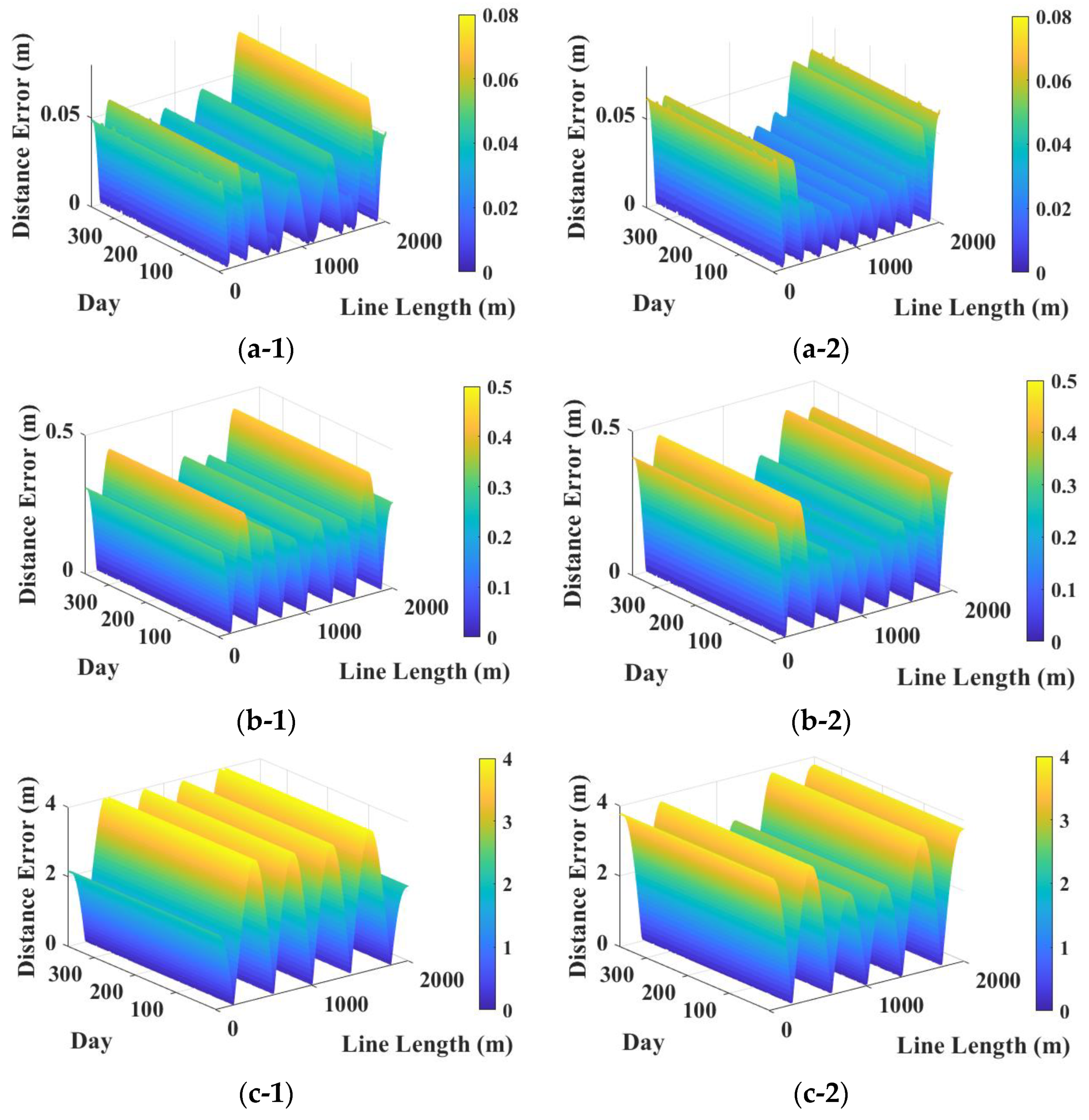
To evaluate the performance of the optimized solutions, the mean distance error (MDE) is calculated for the entire line for all 365 daily simulations, as demonstrated in Figure 7. It is important to highlight that the purpose of optimizing sensor locations is to improve the accuracy of predicting the line motion. In other words, our ultimate goal is to precisely estimate the discrete positions of the line at each time step using the sensor measurements. Consequently, a smaller MDE between the predicted and actual line positions is desirable. The left and right columns in Figure 7 represent the results for uniform and optimized sensor placements, respectively.
It is vividly observed from the figure that as the number of sensors decreases, the MDE increases. Additionally, optimizing sensor locations reduces the height of the error surface slightly. To quantitatively compare the results, the average and maximum MDE values are presented in Table 2. To be specific, the average MDE is computed by averaging the error across all discrete points on the line and over all daily simulations. Similarly, the maximum MDE refers to the largest error found on the entire error surface shown in Figure 7. While the optimized sensors exhibit a slightly lower average MDE compared to the uniformly distributed sensors for all three runs, the maximum error increased slightly when six intermediate sensors were optimized.
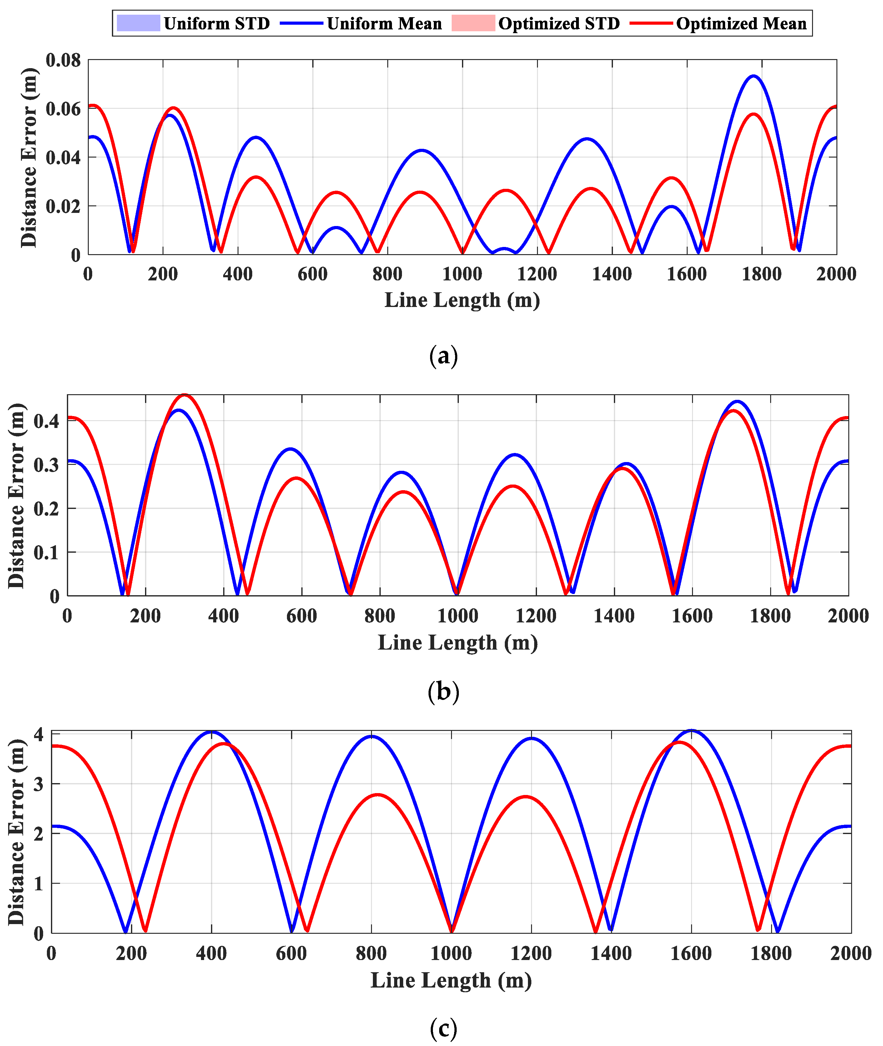
To further scrutinize the results, the MDE and its standard deviation (STD) are calculated across all simulations at each discrete point along the line as demonstrated in Figure 8. The blue and red solid curves represent the average MDEs for uniform and optimized sensor locations, respectively. The shaded areas indicate one STD away from the mean at each discrete position of the line. Nonetheless, shaded areas are not visible in the plots because the MDE was nearly identical for all 365 simulations, as also indicated in Figure 7. It is evident from the figure that the optimized sensors outperform the uniformly placed sensors over a larger portion of the line for all three different numbers of intermediate sensors.
The Case Study I shows minor improvements through optimization. The major reasons can be associated with the relatively narrow frequency range of input loadings since only waves are considered without any second-order wave loads and no wind loads are taken into account; no initial curvature and no discontinuity of the tunnel shape; and sinusoidal-like dominant mode shapes at the given tunnel configuration and boundary conditions as presented in Figure 4, which results in large motions around uniformly distributed sensor locations. Riser monitoring, a more complex case involving environmental loadings across a wider range of frequencies, moving end boundary conditions induced by floater motions, and a more radical initial curve shape, will be discussed in the next section.

3.2. Case Study II: Steel Catenary Riser Attached to Floating Production Storage and Offloading Vessel

3.2.1. Case Description

A generic FPSO with a spread mooring system and a single SCR was designed to further verify the developed algorithm, as shown in Figure 9. The principal dimensions of the FPSO and particulars of the mooring and SCR are given in Table 3 and Table 4. The FPSO had 12 spread mooring lines with a chain-polyester-chain configuration. One steel catenary riser was located, which was arrayed parallel to the y-axis. The same design as in Ref. [37] was used.
The time-domain equation of motion for the FPSO was based on the Cummins equation [38]:
M + M a x ¨ + K h x = F w + F w d + F c + F d + F s ,
where [ M a ( ) ] is the added mass matrix at the infinity frequency, and [ K H ] is the stiffness matrix, i.e., hydrostatic restoring stiffness and gravitational stiffness, { F w } is the first-order wave-excitation load vector, { F w d } is the difference-frequency wave load vector, { F c } is the radiation-damping load vector, { F d } is the viscous drag load vector from wind and current, and { F s } is the connection load vector. There are six degrees of freedom motions to be solved, i.e., surge, sway, heave, roll, pitch, and yaw. { F w d } was obtained by Newman’s approximation, by which off-diagonal terms in the quadratic transfer function were obtained from diagonal terms, and Aranha’s formulation was used for correcting diagonal terms due to current-wave interactions. { F d } was computed by the OCIMF formulation. { F s } was induced to couple FPSO with mooring lines or riser. The mooring lines and riser were modeled by the lumped mass method, the same modeling methodology used for the underwater inclined tunnel. All hydrodynamic coefficients and wave excitation forces were obtained by frequency-domain 3D diffraction/radiation program. The details of the formulation and modeling methodology are given in Ref. [39].
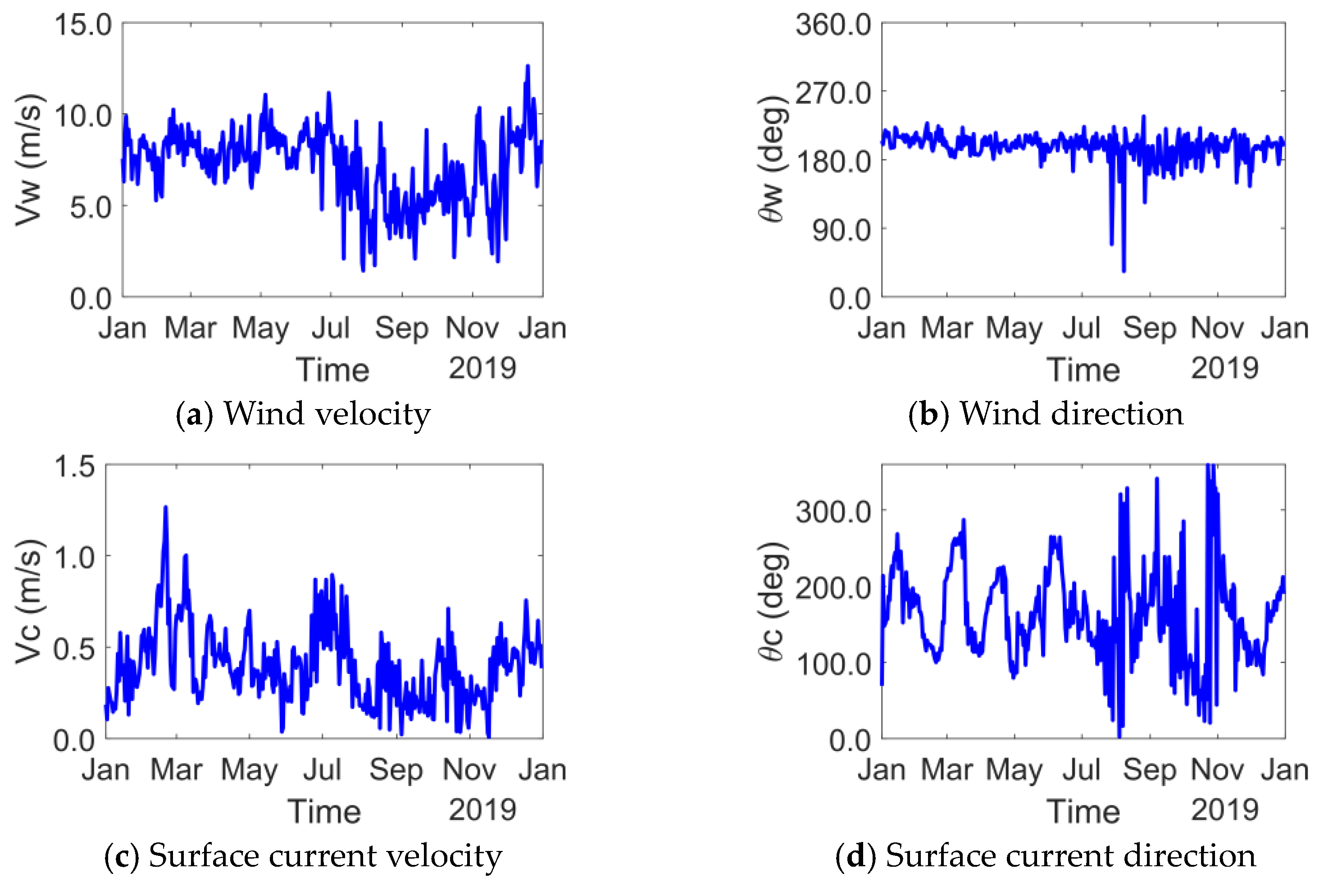
The same environmental conditions as in Case Study I were adopted. In this case, wind and current data were further taken into account. Wind and current data were, respectively, collected from ERA5 and HYCOM (The Hybrid Coordinate Ocean Model) at the same location, as summarized in Figure 10. The water depth was 1500 m. Time histories of the wind velocity were generated by the NPD spectrum. As with the first case study, a total of 365 simulations were conducted, each lasting 30 min with a time step of 0.25 s and a data logging time of 0.5 s. Considering the complex shape of the riser and its coupled interactions under wind, wave, and current conditions, the case presents intricate line behaviors. Thus, the given case is more challenging for line behavior monitoring compared to Case Study I.

3.2.2. Results and Discussion

Similar to the previous case study, the optimization was performed for three different numbers of intermediate sensors: 10, 8, and 6. Since the length of the riser is longer than that of the horizontal pipe, more sensors are utilized to monitor its motion. The optimized sensor locations are shown in Figure 11. Identical to Figure 6, blue circles and red asterisks represent the positions of uniform and optimized sensors, respectively. Unlike the results from the horizontal pipe case, the optimized sensors for riser monitoring manifest an apparent deviation from the uniformly distributed sensors. For all three optimization runs, it is challenging to discover a common pattern. Nevertheless, sensors near the left end of the riser (i.e., where the length equals zero) tend to shift toward the left end.
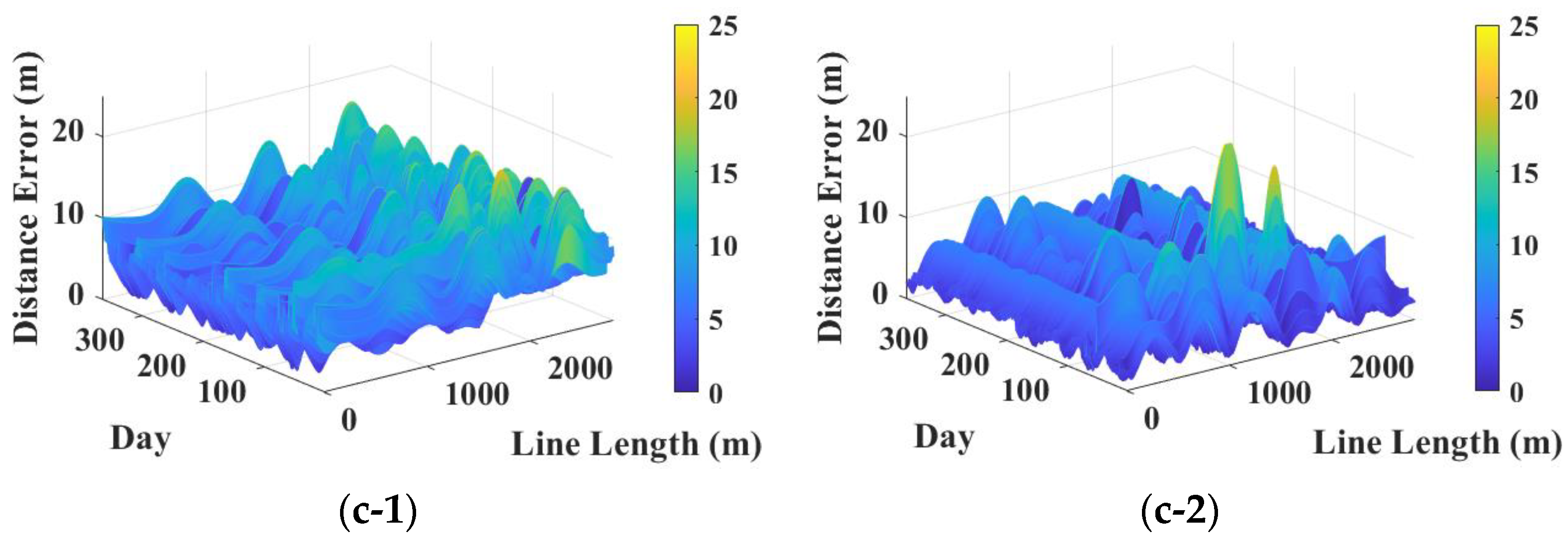
Figure 12 presents the MDE for all discrete positions of the line across all daily simulations. The left and right columns demonstrate the prediction performance for uniform and optimized sensor locations, respectively. Furthermore, rows (a), (b), and (c) represent results for deployments of 10, 8, and 6 intermediate sensors, in that order. It is evident from the plot that the MDE fluctuates significantly more among different daily simulations for the riser model compared to the horizontal pipe, indicating more dynamic motion. As a result, some simulations exhibit undesired peak errors. Generally, optimizing sensor locations exhibits a smaller MDE compared to uniformly distributed sensors. Furthermore, the MDE typically increases as fewer intermediate sensors are used. However, it is important to note that reducing the number of intermediate sensors from 10 to 8 significantly compromises the performance of uniform sensors but has less impact on optimized sensors. In fact, the performance of 10 uniformly located sensors is comparable to that of 8 optimally placed sensors. For a quantitative comparison, average and maximum MDEs were computed and are illustrated in Table 5. The numerical results clearly indicate that optimizing sensor location is extremely effective, particularly when the line experiences highly dynamic behavior. According to the average MDE, 10 and 8 uniformly distributed sensors can be replaced by 8 and 6 optimized sensors, respectively. One of the key aspects of underwater line monitoring is to reduce the number of sensors to minimize the cost and maintenance. Therefore, the presented results in Table 5 are critical as they clearly show that the given optimization reduces the number of sensors while maintaining accuracy.
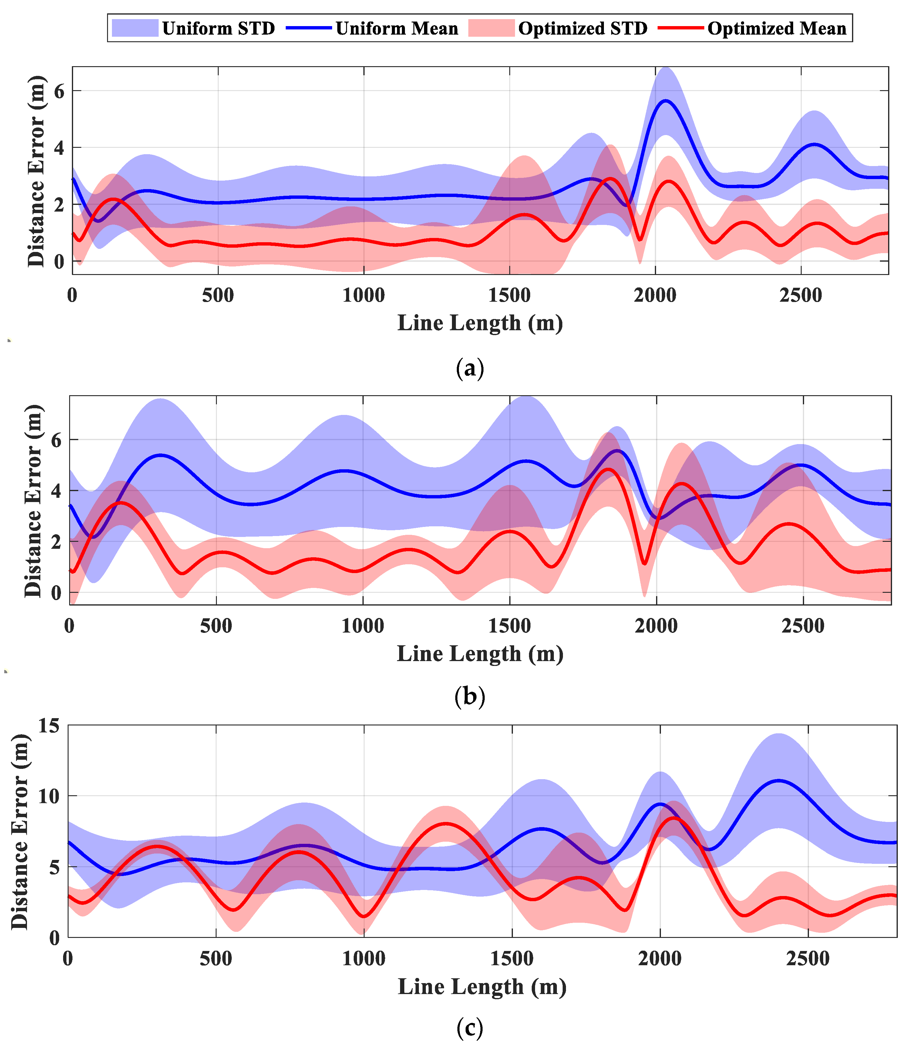
For an in-depth analysis, the average MDE and STD are computed across all daily simulations as depicted in Figure 13. In the figure, rows 1, 2, and 3 represent the results for different numbers of intermediate sensors: 10, 8, and 6, respectively. MDE and STD values are shown along the entire line. The blue and red solid curves represent the average MDE for uniform and optimized sensor locations, respectively, while the STD of the errors is illustrated by the shaded areas in blue and red. Since MDE varies across different simulations, the STD is more apparent in Figure 13 compared to Figure 8. Over almost the entire range of the line, the optimized sensors outperform the uniformly distributed sensors. The greater fluctuations in STD observed in Case Study II are attributed to the highly curved initial shape of the riser, with a minor discontinuity near the touch-down zone, as well as both low- and wave-frequency riser excitations. Low-frequency excitation is mainly induced by wind and second-order difference-frequency wave loads on the FPSO, while wave-frequency excitation is due to wave and current load on both the FPSO and the riser. This complexity results in lower accuracy compared to Case Study I; however, the optimized sensor arrangement significantly enhances accuracy.
There are several challenges associated with the application of the present methodology. First, the Fourier series in nature struggles to express radical shape changes when only a few sensors are used, and a small number of sensors may face challenges in capturing high-frequency excitations, such as those induced by vortex-induced vibrations. However, these limitations can be addressed through optimization. By introducing an optimization process, it was proven that the number of sensors can be reduced while maintaining accuracy. Another challenge is the optimization of sensor locations. The optimization must be applied on a case-by-case basis, allowing sensor locations to be adjusted for each specific structure.

4. Conclusions

This study introduces a real-time line monitoring method based on the Fourier series and inclinometers. Specifically, the method employs angle measurements at multiple points along the line, as well as displacement and curvature data at both ends. To enhance performance, sensor locations were optimized using a GA by minimizing the MDE. The proposed method was validated through two numerical examples: an underwater inclined tunnel and a SCR. The key findings from these case studies are as follows:
  • Increasing the number of sensors improved accuracy by capturing critical line excitations more effectively.
  • For Case Study I, optimization yields only marginal improvements. This is due to the narrow frequency range of input loads, which involves only wave-induced forces without second-order wave loads, the absence of initial curvature or discontinuities in the tunnel shape, and the sinusoidal-like dominant mode shapes under the given configuration and boundary conditions. These factors lead to large displacements around uniformly distributed sensor locations, diminishing the benefit of optimization.
  • For Case Study II, optimization significantly improves accuracy. The large standard deviation fluctuations observed in Case Study II are attributed to the riser’s highly curved initial shape, minor discontinuities near the touch-down zone, and low- and high-frequency riser excitations from both environmental loads and FPSO motions. These factors make uniform sensor placement less effective, and optimization highlights the importance of identifying the best sensor locations.
  • Optimization can reduce the required number of sensors. In Case Study II, the performance of 8 optimally placed intermediate sensors is comparable to that of 10 uniformly distributed intermediate sensors. While previous studies on riser monitoring focused primarily on minimizing the number of sensors, optimizing sensor placement provides a viable alternative for solving this challenge.
While the current study demonstrates the feasibility of the proposed method through synthetic data, verifying the method using measured data is critical since several uncertainties may appear in measured data such as sensor noise. The proposed methodology can be utilized for evaluating the line stress and fatigue damage. Additionally, the optimal selection of Fourier series terms could further enhance performance. Future work will explore these aspects to improve both accuracy and robustness.

Author Contributions

Conceptualization, C.J. and S.H.H.; methodology, C.J. and S.H.H.; software, C.J. and S.H.H.; validation, C.J. and S.H.H.; formal analysis, C.J. and S.H.H.; investigation, C.J. and S.H.H.; resources, C.J. and S.H.H.; data curation, C.J. and S.H.H.; writing—original draft preparation, C.J. and S.H.H.; writing—review and editing, C.J. and S.H.H.; visualization, C.J. and S.H.H.; project administration, C.J.; funding acquisition, C.J. All authors have read and agreed to the published version of the manuscript.

Funding

Research reported in this publication was supported by an Early-Career Research Fellowship from the Gulf Research Program of the National Academies of Sciences, Engineering, and Medicine. The content is solely the responsibility of the authors and does not necessarily represent the official views of the Gulf Research Program of the National Academies of Sciences, Engineering, and Medicine.

Institutional Review Board Statement

Not applicable.

Informed Consent Statement

Not applicable.

Data Availability Statement

The raw data supporting the conclusions of this article will be made available by the authors on request.

Conflicts of Interest

The authors declare no conflicts of interest.

References

  1. Bogue, R. Underwater robots: A review of technologies and applications. Ind. Robot Int. J. 2015, 42, 186–191. [Google Scholar] [CrossRef]
  2. Huvenne, V.A.; Robert, K.; Marsh, L.; Lo Iacono, C.; Le Bas, T.; Wynn, R.B. ROVs and AUVs. In Submarine Geomorphology; Springer: Cham, Switzerland, 2018; pp. 93–108. [Google Scholar]
  3. Cruz, N.A.; Matos, A.C.; Almeida, R.M.; Ferreira, B.M.; Abreu, N. TriMARES-a hybrid AUV/ROV for dam inspection. In Proceedings of the OCEANS’11 MTS/IEEE KONA, Waikoloa, HI, USA, 19–22 September 2011; pp. 1–7. [Google Scholar]
  4. Shilling, R.; Campbell, M.; Howells, H. Drilling riser vortex induced vibration analysis calibration using full scale field data. In Proceedings of the Deep Offshore Tech Conference, Vitoria, Espirito Santo, Brazil, 2–5 May 2005. [Google Scholar]
  5. Tognarelli, M.A.; Taggart, S.; Campbell, M. Actual VIV fatigue response of full scale drilling risers: With and without suppression devices. In Proceedings of the International Conference on Offshore Mechanics and Arctic Engineering, Estoril, Portugal, 15–20 June 2008; pp. 513–525. [Google Scholar]
  6. McNeill, S.; Agarwal, P. Efficient modal decomposition and reconstruction of riser response due to VIV. In Proceedings of the International Conference on Offshore Mechanics and Arctic Engineering, Rotterdam, The Netherlands, 19–24 June 2011; pp. 345–354. [Google Scholar]
  7. Saruhashi, T.; Kluk, D.J.; Kyo, M.; Bhalla, K.; Sawada, I.; Miyazaki, E.; McNeill, S.; Yamazaki, Y. Development of a real-time riser fatigue monitoring system. In Proceedings of the Offshore Technology Conference, Houston, TX, USA, 6–9 May 2013; p. OTC–24216–MS. [Google Scholar]
  8. Mukundan, H.; Hover, F.; Triantafyllou, M. A systematic approach to riser VIV response reconstruction. J. Fluids Struct. 2010, 26, 722–746. [Google Scholar] [CrossRef]
  9. Mercan, B.; Campbell, M.; Thompson, C. Fatigue Monitoring and Life Extension for Top Tensioned Production Riser Systems. In Proceedings of the Offshore Technology Conference, Virtual, Houston, TX, USA, 16–19 August 2021; p. D021S017R006. [Google Scholar]
  10. Bakker, M. An Alternative Methodology for Riser Lifetime Prediction. Master’s Thesis, Department of Offshore Engineering, Delft University of Technology, Delft, The Netherlands, 2011. [Google Scholar]
  11. Wang, J.; Sheng, L.; Geng, Y.; Wang, M.; Wang, Y.; Li, Y.; Liu, X. Fatigue damage assessment methodology for a deepwater subsea wellhead based on monitoring data. Ships Offshore Struct. 2023, 1–13. [Google Scholar] [CrossRef]
  12. Ge, M.L.; Kannala, J.; Li, S.; Maheshwari, H.; Campbell, M. A new riser fatigue monitoring methodology based on measured accelerations. In Proceedings of the International Conference on Offshore Mechanics and Arctic Engineering, San Francisco, CA, USA, 8–13 June 2014; p. V06AT04A063. [Google Scholar]
  13. Mercan, B.; Chandra, Y.; Maheshwari, H.; Campbell, M. Comparison of Riser Fatigue Methodologies Based on Measured Motion Data. In Proceedings of the Offshore Technology Conference, Houston, TX, USA, 2–5 May 2016. [Google Scholar]
  14. Kim, H.; Jin, C.; Kim, M. Real-time estimation of riser’s deformed shape using inclinometers and Extended Kalman Filter. Mar. Struct. 2021, 77, 102933. [Google Scholar] [CrossRef]
  15. Choi, J.; Kim, J.M.-H. Development of a new methodology for riser deformed shape prediction/monitoring. In Proceedings of the International Conference on Offshore Mechanics and Arctic Engineering, Madrid, Spain, 17–22 June 2018; p. V005T004A041. [Google Scholar]
  16. Blondeau, S.; Andre, M.; Garnier, P.; Benmedakhene, S.; Quesnel, J. Riser integrity monitoring system for offshore fields. In Proceedings of the Offshore Technology Conference Asia, Kuala Lumpur, Malaysia, 25–28 March 2014; pp. OTC–24791–MS. [Google Scholar]
  17. Inaudi, D.; Glisic, B.; Gasparoni, F.; Cenedese, S.; Zecchin, M. Strain sensors for deepwater applications. In Proceedings of the Proceedings of the 3rd International Conference on Structural Health Monitoring of Intelligent Infrastructure, Vancouver, BC, Canada, 13–16 November 2007. [Google Scholar]
  18. Brower, D.; Hedengren, J.D.; Shishivan, R.A.; Brower, A. Advanced deepwater monitoring system. In Proceedings of the International Conference on Offshore Mechanics and Arctic Engineering, Nantes, France, 9–14 June 2013; p. V001T001A048. [Google Scholar]
  19. Sundararaman, S.; Thethi, R.; Hill, M. Data driven virtual sensors for riser prognostic integrity management. In Proceedings of the Offshore Technology Conference, Houston, TX, USA, 30 April–3 May 2018; p. D011S014R006. [Google Scholar]
  20. Repalle, N.; Thethi, R.; Viana, P.; Tellier, E. Application of Machine Learning for Fatigue Prediction of Flexible Risers-Digital Twin Approach. In Proceedings of the SPE Asia Pacific Oil and Gas Conference and Exhibition, Virtual, 17–19 November 2020; p. D013S104R005. [Google Scholar]
  21. Sivaprasad, H.; Lekkala, M.R.; Latheef, M.; Seo, J.; Yoo, K.; Jin, C. Fatigue damage prediction of top tensioned riser subjected to vortex-induced vibrations using artificial neural networks. Ocean Eng. 2023, 268, 113393. [Google Scholar] [CrossRef]
  22. Lekkala, M.R.; Latheef, M.; Jung, J.H.; Kim, Y.T. Fatigue damage assessment of offshore riser subjected to vortex-induced vibrations by SHEAR7. Int. J. Nav. Archit. Ocean Eng. 2022, 14, 100464. [Google Scholar] [CrossRef]
  23. Rombado, G.; Wadhwa, H.; Cooke, N.; Pasala, D.; Paulin, M.; Rao, P.; Majed, A. A Flexible Riser Digital Twin for Real-Time Monitoring and Asset Management. In Proceedings of the SNAME Offshore Symposium, Virtual, 6–7 April 2021; p. D011S002R007. [Google Scholar]
  24. Chen, M.; Li, C.B.; Han, Z.; Lee, J.-b. A simulation technique for monitoring the real-time stress responses of various mooring configurations for offshore floating wind turbines. Ocean Eng. 2023, 278, 114366. [Google Scholar] [CrossRef]
  25. Albani, Y.; Cavallini, F.; Girello, E.; Lazzarin, D.; Massari, G.; Novello, M. RIMS: A Fully Integrated Technology for Long-Term Riser Monitoring. In Proceedings of the Offshore Technology Conference Brasil, Rio de Janeiro, Brazil, 24–26 October 2023; p. D011S010R005. [Google Scholar]
  26. Jin, C.; Kim, M.-H. Tunnel-mooring-train coupled dynamic analysis for submerged floating tunnel under wave excitations. Appl. Ocean Res. 2020, 94, 102008. [Google Scholar] [CrossRef]
  27. Hong, S.H.; Cornelius, J.; Wang, Y.; Pant, K. Fault compensation by online updating of genetic algorithm-selected neural network model for model predictive control. SN Appl. Sci. 2019, 1, 1–16. [Google Scholar] [CrossRef]
  28. Lambora, A.; Gupta, K.; Chopra, K. Genetic algorithm-A literature review. In Proceedings of the 2019 International Conference on Machine Learning, Big Data, Cloud and Parallel Computing (COMITCon), Faridabad, India, 14–16 February 2019; pp. 380–384. [Google Scholar]
  29. Mirjalili, S.; Mirjalili, S. Genetic algorithm. In Evolutionary Algorithms and Neural Networks: Theory and Applications; Springer: Cham, Switzerland, 2019; pp. 43–55. [Google Scholar]
  30. Katoch, S.; Chauhan, S.S.; Kumar, V. A review on genetic algorithm: Past, present, and future. Multimed. Tools Appl. 2021, 80, 8091–8126. [Google Scholar] [CrossRef] [PubMed]
  31. Lee, S.-L.; Shin, S.J. Structural design optimization of a wind turbine blade using the genetic algorithm. Eng. Optim. 2022, 54, 2053–2070. [Google Scholar] [CrossRef]
  32. Owoyele, O.; Pal, P.; Vidal Torreira, A. An automated machine learning-genetic algorithm framework with active learning for design optimization. J. Energy Resour. Technol. 2021, 143, 082305. [Google Scholar] [CrossRef]
  33. Hamdia, K.M.; Zhuang, X.; Rabczuk, T. An efficient optimization approach for designing machine learning models based on genetic algorithm. Neural Comput. Appl. 2021, 33, 1923–1933. [Google Scholar] [CrossRef]
  34. Han, S.; Sun, X. Optimizing Product Design using Genetic Algorithms and Artificial Intelligence Techniques. IEEE Access 2024, 12, 151460–151475. [Google Scholar] [CrossRef]
  35. Orcina, L. OrcaFlex User Manual, Version 11.4; Orcina: Cumbria, UK, 2023. [Google Scholar]
  36. Jin, C.; Kim, M. The effect of key design parameters on the global performance of submerged floating tunnel under target wave and earthquake excitations. Comput. Model. Eng. Sci. 2021, 128, 315–337. [Google Scholar] [CrossRef]
  37. Kwon, D.-S.; Kim, S.-J.; Jin, C.; Kim, M.; Guha, A.; Esenkov, O.E.; Ryu, S. Inverse estimation of a vertical current velocity profile using motions of an FPSO and artificial neural network. Ocean Eng. 2023, 285, 115343. [Google Scholar] [CrossRef]
  38. Cummins, W. The Impulse Response Function and Ship Motions; David Taylor Model Basin: Washington, DC, USA, 1962. [Google Scholar]
  39. Jin, C.; Kim, S.-J.; Kim, M.; Lee, Y.; Guha, A.; Ryu, S.; Xu, W. Real-time dynamic and structural behavior estimation of a steel lazy wave riser through finite-element-based digital twin and hull-motion sensor. Appl. Ocean Res. 2024, 150, 104137. [Google Scholar] [CrossRef]
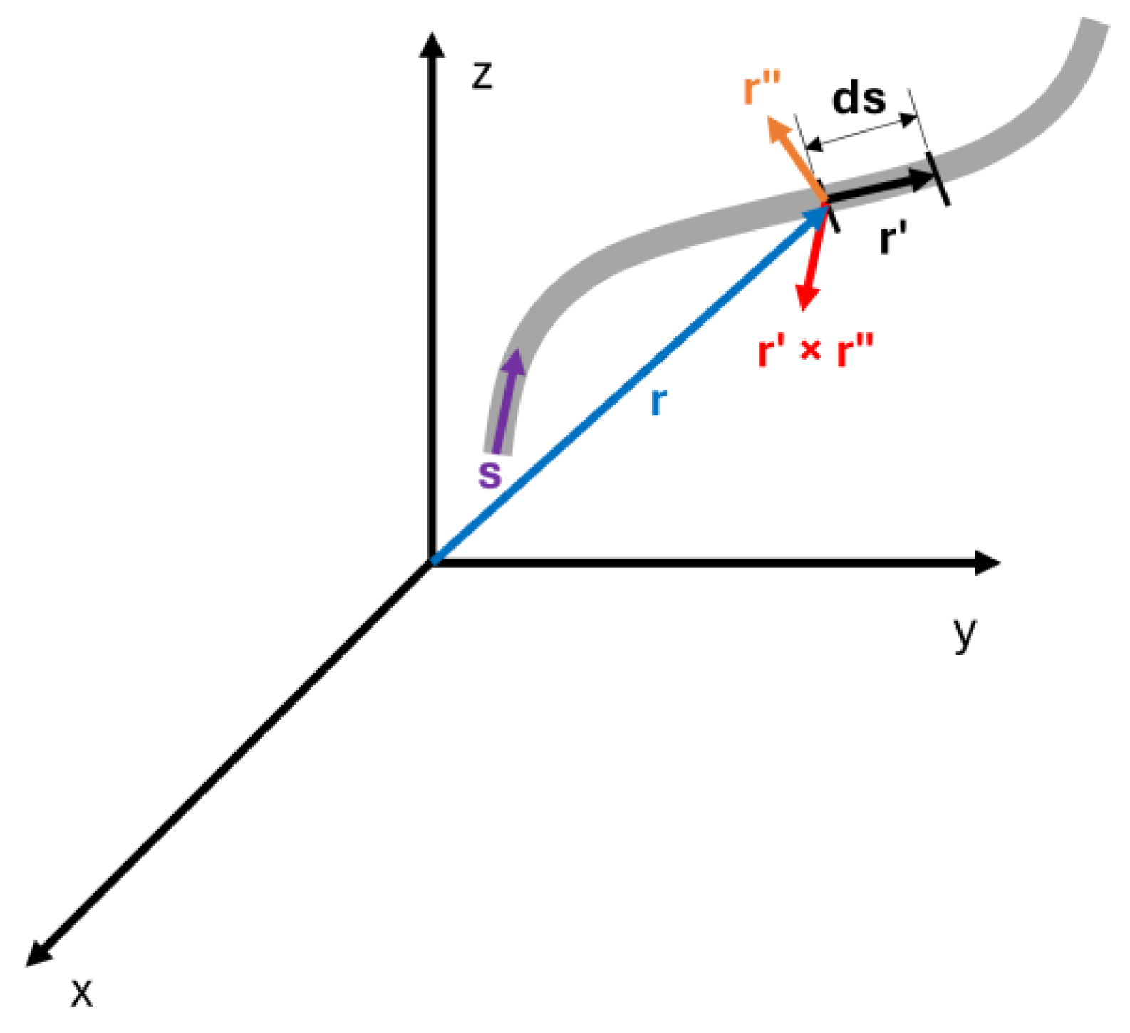
Figure 1. Generalized coordinates defined in the global coordinate system [26].
Jmse 12 01939 g001
Figure 2. Sensor arrangement.
Jmse 12 01939 g002
Figure 3. Numerical model of the underwater inclined tunnel in OrcaFlex (front view).
Jmse 12 01939 g003
Figure 4. Wet natural frequencies and mode shapes up to the first 15 modes.
Jmse 12 01939 g004
Figure 5. One-year wave conditions (−56 degrees east and 10 degrees north).
Jmse 12 01939 g005
Figure 6. Optimized locations of different numbers of intermediate sensors: (a) 8, (b) 6, and (c) 4.
Jmse 12 01939 g006
Figure 7. Mean distance error for all 365 daily simulations for the entire line. Left and right columns show results of uniform and optimized sensor locations, respectively. Furthermore, (a), (b), and (c) refer to 8, 6, and 4 intermediate sensors, respectively.
Jmse 12 01939 g007
Figure 8. Average mean distance error and its standard deviation for different numbers of intermediate sensors: (a) 8, (b) 6, and (c) 4.
Jmse 12 01939 g008
Figure 9. Numerical model of moored FPSO in OrcaFlex.
Jmse 12 01939 g009
Figure 10. One-year wind and current conditions (−56 degrees east and 10 degrees north).
Jmse 12 01939 g010
Figure 11. Optimized locations of different numbers of intermediate sensors: (a) 10, (b) 8, and (c) 6.
Jmse 12 01939 g011aJmse 12 01939 g011b
Figure 12. Mean distance error for all 365 daily simulations for the entire line. Left and right columns show results of uniform and optimized sensor locations, respectively. Furthermore, (a), (b), and (c) refer to the number of intermediate sensors 10, 8, and 6, respectively.
Jmse 12 01939 g012aJmse 12 01939 g012b
Figure 13. Average mean distance error and its standard deviation for different numbers of intermediate sensors: (a) 10, (b) 8, and (c) 6.
Jmse 12 01939 g013
Table 1. Design particulars for the underwater inclined tunnel example.
ParameterValueUnit
Length2000m
Outer diameter10m
Shell thickness1.22m
End boundary conditionHinged boundary condition-
Mass/unit length80.5t/m
BWR1.0-
Axial stiffness1.01 × 109kN
Bending stiffness9.89 × 109kNm2
Torsional stiffness8.24 × 109kNm2
Added mass coefficient1.0-
Drag coefficient0.55-
Table 2. Average and maximum mean distance error comparison.
Number of Intermediate Sensors
864
Average mean distance errorUniform0.0281 m0.2230 m2.3367 m
Optimized0.0252 m0.2182 m2.2234 m
Maximum mean distance errorUniform0.0734 m0.4441 m4.0695 m
Optimized0.0641 m0.4591 m3.8330 m
Table 3. Design particulars for FPSO.
ParameterValueUnit
Length between perpendicular (Lpp)310m
Breadth (B)47.17m
Depth (H)28.04m
Draft (d)18.90m
Displacement240,869MT
Center of gravity above base (KG)13.30m
Roll radius of gyration at CoG (Rxx)14.77m
Pitch radius of gyration at CoG (Ryy)77.47m
Yaw radius of gyration at CoG (Rzz)79.30m
Heave natural period14.62s
Roll natural period12.88s
Pitch natural period11.79s
Table 4. Design particulars for mooring lines and SCR.
ParameterValueUnit
Mooring LinesSteel
Catenary
Riser
Segment 1
(Chain)
Segment 2
(Polyester)
Segment 3
(Chain)
Length1202290902800m
Diameter *9.5216.09.5225.4cm
Mass/unit length189.220.4189.2131.0kg/m
Axial stiffness9.12 × 1052.79 × 1049.12 × 1053.34 × 106kN
Bending stiffness---2.25 × 10⁴kNm2
Torsional stiffness---1.84 × 10⁴kNm2
Added mass coefficient **1.01.01.01.0-
Drag coefficient2.41.22.41.0-
* For the mooring lines, this is the nominal diameter. ** The equivalent diameter is used to determine these coefficients.
Table 5. Average and maximum mean distance error comparison.
Number of Intermediate Sensors
1086
Average mean distance errorUniform2.6512 m4.1470 m6.5259 m
Optimized1.0960 m1.9135 m4.2016 m
Maximum mean distance errorUniform17.7508 m15.7451 m19.4728 m
Optimized11.7648 m14.6098 m25.4105 m
Disclaimer/Publisher’s Note: The statements, opinions and data contained in all publications are solely those of the individual author(s) and contributor(s) and not of MDPI and/or the editor(s). MDPI and/or the editor(s) disclaim responsibility for any injury to people or property resulting from any ideas, methods, instructions or products referred to in the content.