Article

Adaptive Pitch-Tracking Control with Dynamic and Static Gains for Remotely Operated Towed Vehicles

1
International Co-Operation Platform of Intelligent Ocean Equipments Technology of Zhejiang Province, Hangzhou Dianzi Univeristy, Hangzhou 310023, China
2
School of Mechanical Engineering, Hangzhou Dianzi University, Hangzhou 310018, China
3
School of Mechanical and Electrical Engineering, China University of Mining and Technology, Xuzhou 221116, China
4
State Key Laboratory of Satellite Ocean Environment Dynamics, Second Institute of Oceanography, Ministry of Natural Resourcs, Hangzhou 310012, China
5
School of Electronics and Information, Hangzhou Dianzi University, Hangzhou 310018, China
*
Authors to whom correspondence should be addressed.
J. Mar. Sci. Eng. 2024, 12(11), 1953; https://doi.org/10.3390/jmse12111953
Submission received: 8 September 2024 / Revised: 21 October 2024 / Accepted: 25 October 2024 / Published: 31 October 2024

Abstract

:
The pitch angle regulation in Remotely Operated Towed Vehicles (ROTVs) is essential to ensure the robustness of emitted signals within the maritime surveillance domain. Characterized by inherent nonlinear dynamics and stochastic uncertainties, the pitch angle model poses significant challenges to conventional tracking controls relying on linearization. This study introduces an adaptive pitch-control algorithm designed for ROTVs, which adeptly manages nonlinear dynamics as well as unmeasurable states through a synergistic integration of dynamic and static gains. A key feature of our approach is the incorporation of a high-order observer that adeptly estimates the system’s unmeasurable states, thereby enhancing control precision. Our proposed algorithm greatly exceeds traditional PID and fuzzy PID methods in both settling time and steady-state error, particularly in high-order nonlinear and unmeasurable state scenarios. Compared to sliding mode control, the proposed control strategy improved the settling time by 74% and the steady-state error was enhanced from 10 6 to 10 8 , as confirmed by numerical simulations. The efficacy of the algorithm in achieving the desired tracking trajectories highlights its potential for deep-water operations and fine-tuned attitude adjustments for ROTVs.

1. Introduction

Marine equipment is crucial to ocean geographical surveys, the exploitation of mineral resources, and the protection of marine ecosystems [1,2,3,4,5,6]. Remotely Operated Towed Vehicles (ROTVs), connected to the mother ship by a cable, are widely used for gas hydrate explorations, marine biology surveys, and environmental data collection [7,8,9,10,11,12]. To ensure high-quality data are obtained in complex underwater environments, it is essential to enhance the stability of ROTV control [13,14]. However, the dynamics of the ROTV are distinctly nonlinear due to its susceptibility to multiple forces, including buoyancy, resistance, gravity, and towing cable tension. Furthermore, due to the limitations of sensor performance and environmental interference, it is difficult to accurately measure the actual motion state of the ROTV when executing tasks [15,16,17]. Therefore, the development of a class of control algorithms considering both the nonlinearity and unmeasurable states for the ROTV system is necessary.
The ROTV’s nonlinear properties make it challenging to maintain a stable attitude. Many researchers have directly fixed the tail fins to increase stability, regardless of the effects on the system’s nonlinearity [18,19,20]. The Proportional–Integral–Derivative (PID) algorithm is proposed to control the ROTV system by linearizing its nonlinear components [21,22,23]. Researchers have conducted in-depth studies on the controllability of linear strong structures and their related applications [24,25,26,27]. However, it is crucial to recognize that linearization might not always succeed in tracking time-varying trajectories. Specifically, controllability could be problematic at certain operating points due to a low-ranked controllability matrix, potentially reducing the PID controller’s efficacy [28]. New control algorithms have emerged to improve the controlling performance of ROTVs. Liu used a finite-time fuzzy adaptive control scheme, considering model nonlinear and wave disturbances, to control the depth and pitch angle of ROTVs [29]. However, this approach may overlook the influence of the tension of the towing cable, leading to potential instability and infeasibility in trajectory tracking. Minowa used a high-gain observer, considering the depth and pitch nonlinearity of the towed vehicle, to control its depth and attitude with the Linear Quadratic Inversion (LQI) method [30]. Nevertheless, this method fails to account for the influence of depth and attitude coupling, which reduces the model’s reliability in challenging operational scenarios. Additionally, it is important to note that a high-gain observer can introduce excessive noise, further complicating control efforts in challenging environments. Although the previous approaches have produced satisfactory results, the control algorithm still has much more space for improvement given the high-order nonlinear features of ROTVs.
The ROTV system is influenced not only by its nonlinear dynamic behaviors but also by the inherent uncertainty encountered in practice; for instance, unmeasurable states [31]. Adaptive control methods are reliable approaches for managing complex uncertainty issues [32]. Teixeira introduced an adaptive control strategy that incorporates an observer to estimate unmeasurable velocity states. This approach has consistently demonstrated robust performance across various equilibrium states [33]. Another adaptive controller, constrained by the upper bounds of the system’s unmeasurable state, has demonstrated excellent performance in tracking the trajectories of ROTVs, even in the presence of numerous obstacles. Although adaptive strategies have proven effective in dealing with the unmeasurable states of the ROTV system, they may fall short in terms of real-time response and adaptability to varying conditions [34]. Output feedback control can be used to enhance the performance of the entire control system [35]. Sliding mode output feedback control excels in handling system uncertainties by establishing a sliding surface that guides the system state and slides along it to the desired equilibrium state, demonstrating strong robustness to external disturbances and variations in model parameters [36,37]. However, when high-gain observers are required, the control may be overly sensitive to measurement noise, which can affect the precision of control and system stability. Output feedback that has been integrated into the control system could dynamically adjust to the current state of the system and external disturbances, ensuring a more robust and responsive control strategy [38].
Based on the aforementioned research, the nonlinearity of ROTVs and the unmeasurable states due to sensor limitations make the design of a controller relatively challenging. This paper introduces an algorithm that addresses the nonlinear aspects, considering both dynamic and static gains observers. This novel algorithm considers the nonlinear and unmeasurable coupling states based on the growth conditions of the nonlinear terms.
The contributions of this paper are as follows:
  • A nonlinear adaptive output feedback tracking control algorithm is proposed, aimed at studying the attitude compensation during the motion of an ROTV, with the objective of controlling the pitch angle trajectory tracking problem of ROTVs;
  • By employing a novel dynamic and static gain observer, the controller design issue is transformed into a problem of parameter computation and selection, thereby addressing the system’s nonlinearity and the handling of unmeasurable states;
  • Global practical output tracking with globally bounded states is demonstrated for the ROTV system through appropriate design parameter selection.
This paper is organized as follows: Section 2 introduces the physical characteristics of the ROTV and establishes the dynamic model of the towed system. Section 3 presents the details of the tracking control algorithm, combining dynamic and static gains. Section 4 provides comparative performances and analyses of the controllers using four proposed schemes: PID, fuzzy PID, sliding mode control, and proposed control methods. Section 5 summarizes the whole work.

2. Preliminaries

2.1. Description of the Towed Vehicle

An underwater towing system consists of three parts: a mother ship, a towing cable, and an ROTV. Figure 1 presents a schematic representation of an ROTV along with the coordinate systems utilized throughout this study. Within the local coordinate system ( o x b y b z b ), the velocity and angular velocity of the ROTV are calculated and the position and orientation are transformed to the global coordinate system ( O x y z ). The nonlinear dynamic equations of ROTVs, which incorporate the forces of the towing cable and sea currents, can be mathematically represented as follows [22]:
M 𝓋 ˙ + C 𝓋 𝓋 + D 𝓋 𝓋 + g ϵ = τ u + F s ,
ϵ ˙ = J ϵ 𝓋 ,
where 𝓋 = u   υ   w   p   q   r T is the velocity vector of the ROTV, ϵ = x   y   z   φ   θ   ψ T is the acceleration vector of the ROTV, M is the inertial mass matrix including the added mass, C 𝓋 is a Coriolis centripetal matrix containing additional masses, D 𝓋 is the damping matrix, and g ϵ is the gravitational/buoyancy force and moment vector. The control input τ u is the force and moment of the ROTV. F s is the pull force of the towing cable acting on the vehicle, including the tension, gravity/buoyancy, and resistance of the cable. J (ϵ) is the transform matrix converting 𝓋 to ϵ ˙ .

2.2. Pitch-Control Model

Because the six degrees of freedom (DOF) model of the towed vehicle described above has strong coupling with the cable and flow current, it is not conducive to the design of the controller. Accordingly, considering the characteristic operation of ROTVs under different sea conditions, the following assumptions are made. These assumptions are designed to isolate the most salient features of the ROTV’s motion, thereby facilitating a more tractable analysis:
  • It is assumed that the control of pitch attitude commences once the towing system has reached a steady state, during which the parameters of the ROTV in the horizontal plane remain constant;
  • Our attention is mostly focused on the pitch motion of the ROTV within the vertical plane;
  • The model is based on the lumped mass approach, considering the tension forces transmitted from the cable to the center of gravity of the ROTV.
Based on the aforementioned assumptions, the pitch channel model for the ROTV can be expressed by the following mathematical formulation:
θ ˙ = q q ˙ = w + f 1 t , θ , w , q w ˙ = u t + f 2 t , θ , w , q ,
f 1 t , θ , w , q = 1 I y M q ˙ [ M 0 u 1 2 + M w u 1 w + M q u 1 q + M q q q 2 2 m 0 x G u 1 q m 0 z G w q z G G z C B sin θ x G G x C B cos θ + M y w ] ,
f 2 t , θ , w , q = 1 m 0 Z w ˙ [ Z 0 u 1 2 + Z w u 1 w + Z q u 1 q + Z w w w 2 + G B cos θ + m u q + Z q q 2 + F z ] ,
M y = y t p × F y ,
where θ represents the pitch angle; u 1 denotes the longitudinal velocity, which is considered to be constant; w and q are the vertical velocity and pitch angle velocity, respectively, whose temporal functions reflect the high-order nonlinear characteristics of the ROTV system; m is the mass of the ROTV; I y signifies the moment of inertia about the pitch axis; G and B are the gravitational force and buoyant force applied to the ROTV; x G   0   z G is the coordinate of the ROTV center. x C   0   z C is the coordinate of the buoyancy center of the ROTV; M w ,   M q ,   M q q ,   M q ˙ ,   Z w ˙ ,   Z q ,   Z w ,   Z w w represents the hydrodynamic derivatives; F y   and F z are the components of the drag force in the y and z directions, respectively; u t is the input control used to attain the preset trajectory.

2.3. Presupposition

This section presents three assumptions used to address global tracking problem (3), determining whether the control model satisfies the polynomial growth condition.
Assumption 1.
To facilitate the design of the control algorithm, we first introduce the following transformation:
ξ 1 = θ ,   ξ 2 = w , ξ 3 = q ,
Equation (3) can be converted to:
ξ ˙ 1 = ξ 2 + φ 1 t , ξ ξ ˙ 2 = ξ 3 + φ 2 t , ξ ξ ˙ 3 = u t + φ 3 t , ξ y = ξ 1 y r t .
In the stochastic nonlinear system shown in Formula (6), ξ = ξ 1 , ξ 2 , ξ 3 T R 2 ,   u t R ,   y R are the states, input, and output of the system, respectively; y r is the expectation trajectory. The nonlinear term φ t , ξ = φ 1 t , ξ ,   φ 2 t , ξ ,   φ 3 t , ξ T = 0 , f 1 t , ξ , f 2 t , ξ T : + × × 2 satisfies the continuous polynomial growth conditions and local Lipschitz [39]. In the example presented in this paper, it is assumed that only the system output y can be measured, which implies that   ξ 1 ,   ξ 2 ,   ξ 3 , and y r may be unmeasurable. The mathematical implications of such unmeasurable state are detailed in Appendix A.
Assumption 2.
It is known that there exists an integer  p     1 and a known constant c 0     0 , such that the following formula holds true:
φ i t , ξ b 0 1 + ξ 1 p ξ 1 + + ξ i + b 0 ,         i = 1 ,   2 ,   3 .
Assumption 3.
Assume that trajectory signal  y r satisfies y r b 1 and y ˙ r b 2 for t 0 ,   + , where y r is continuously differentiable and b 1 ,   b 2 0 are known constants. The objective of this paper is to develop adaptive output feedback control algorithms by taking the form of the system (8) for any given tolerance δ > 0 . In a closed loop system, there exists a finite time T δ > 0 such that y t = ξ 1 t y r δ ,   t T δ , and all states are globally bounded within 0 ,   + (see [39]).
Assumption 2 shows that the system essentially depends on immeasurable states and that c 0 is not necessarily 0, which allows for low-order growth in immeasurable states. Assumption 3 shows that the design of the controller in this paper requires no more information than the upper bounds of the reference signal y r and its derivatives y ˙ r .
Then, based on Assumptions 2 and 3 and ξ 1 = y + y r , we have
φ i t , ξ b 0 1 + ξ 1 p ξ 1 + + ξ i + b 0 b 0 1 + 2 p 1 c 1 p + 2 p 1 y p ξ 1 + + ξ i + b 0 b 1 + y p ξ 1 + + ξ i + b ,     i = 1 , 2 , 3 ,
where b b 0 m a x 1 + 2 p 1 b 1 p , 2 p 1 0 is a known constant value.

3. Tracking Control Algorithms

To enhance the control efficiency, we developed tracking control algorithms based on Reference [39] for an ROTV that leverages both dynamic and static gain observers. Employing dynamic gain observers, such control algorithms tackle the challenge of polynomial growth inherent in nonlinear systems and ensure the robustness and stability of the system.

3.1. Dynamic and Static Gain Observers and Controller Design

Equation (6) is further transformed to:
x 1 = y = ξ 1 y r ,     x i = ξ i ,     i = 2 , 3 .
Then, we have,
x ˙ 1 = x 2 + ϕ 1 t ,   x x ˙ 2 = x 3 + ϕ 2 t ,   x x ˙ 3 = u t + ϕ 3 t ,   x y = x 1 ,
where
ϕ 1 t ,   x = φ 1 t , x 1 + y r , x 2 , x 3 y ˙ r ϕ 2 t ,   x = φ 2 t ,   x 1 + y r , x 2 , x 3 ϕ 3 t ,   x = φ 3 t ,   x 1 + y r , x 2 , x 3 , u ,
After the state transformation (11), the tracking control problem of system (8) is converted to the stability problem of system (12).
The following state observer is built for system (12):
x ^ ˙ 1 = x ^ 2 + Z l 1 x 1 x ^ 1 x ^ ˙ 2 = x ^ 3 + Z 2 l 2 x 1 x ^ 1 x ^ ˙ 3 = u t + Z 3 l 3 x 1 x ^ 1 ,
Ζ L M t ,
where l = l 1 ,   l 2 ,   l 3 are constants to be determined later.   Ζ is a time-varying function in which L > 1 is the static gain to be provided later, and M t is the dynamic gain updated with 0 < β 1 β 2 , to be determined later.
M ˙ = M β 2 1 + y p 2 β 1 M ,     M 0 = 1 .
If G = M 2 is defined, it can be deduced from Equation (16) that G ˙ 2 β 1 M 2 1 M 2 β 1 G 1 G . Since M 0 , G ˙ 1 = 2 β 1 G 1 1 G 1 with G 1 0 = 1 , then, using the comparison principle, we have G G 1 1 , M 1 . Combining L > 1 leads to Ζ > 1 , so observer (14) is an ordinary Luenberger-type with a dynamic high gain [40]. Based on observer (14), we design the following output feedback controller:
u t = Ζ 3 k 1 x ^ 1 + Ζ 2 k 2 x ^ 2 + Ζ k 3 x ^ 3 ,
where k = k 1 ,   k 2 ,   k 3 is a constant vector to be a determined later. Ζ L M t plays an important role in the output feedback control of the system. To achieve the goal for the control, the static gain L should be sufficiently large. In addition, the dynamic gain M is necessary to deal with the growth rate of the polynomial function of the system. Formula (17) shows that the controller designed in this paper is a linear function of the observer state and is easy to implement.

3.2. Stability Analysis

Subscale transformation is introduced for the stability analysis. The state estimation error is defined as x ˜ = x x ^ . The dynamics of x ˜ satisfies
x ˜ ˙ 1 = Ζ c 1 x ˜ 1 + x ˜ 2 + ϕ 1 x ˜ ˙ 2 = Ζ 2 c 2 x ˜ 1 + ϕ 2 x ˜ ˙ 3 = Ζ 3 c 3 x ˜ 1 + ϕ 3 ,
where c = c 1 ,   c 2 ,   c 3 T . The following scaling transformations are made to simplify the analysis:
ε i = x ˜ i / Ζ a + i 1 ,     i = 1 , 2 , 3 η i = x ^ i / Ζ a + i 1 ,     i = 1 , 2 , 3 ,
where 0 < a < 1 4 p is a constant. If Equation (18) is incorporated into Equation (19), we obtain the following:
ε ˙ = Ζ A ε Ζ ˙ D a ε / r + f η ˙ = Ζ B η Ζ ˙ D a η / r + Ζ l ε 1
where f = ϕ 1 / Ζ a ,   ϕ 2 / Ζ a + 1 ,   ϕ 3 / Ζ a + 2 T = φ 1 y ˙ r / Ζ a ,   φ 2 / Ζ a + 1 ,   φ 3 / Ζ a + 2 T ,
A = c 1 1 0 c 2 0 1 c 3 0 0 ,   B = 0 1 0 0 0 1 k 1 k 2 k 3 ,   D a = a 0 0 0 1 + a 0 0 0 2 + a .
We select the design parameters c i and k i (i=1, 2, 3) to fulfil the Hurwitz condition such that there are constants h i > 0 and symmetric positive definite matrices P, Q, satisfying (see [41]):
P A + A T P I ,         h 1 I P D a + D a P h 2 I Q B + B T Q 2 I ,         h 3 I Q D a + D a Q h 4 I
Let V ε ,   η = α ε T P ε + η T Q η be the potential Lyapunov function, with α = || Q c || 2 + 1 being a known constant. The following inequality (23) on 0 , + is thus satisfied by the time derivative of V along the trajectories of (20).
V ˙ 2 f α ε T P α Ζ || ε || 2 2 Ζ || η || 2 + 2 Ζ η T Q c ε 1 α r ˙ r ε T P D a + D a P ε Ζ ˙ Ζ η T D a Q + Q D a η ,
Using Ζ > 1 , combined with Equation (16), it is derived that Ζ ˙ Ζ = M ˙ M = β 2 1 + y p 2 β 1 M . Thus, as in Equation (22),
α Ζ ˙ Ζ ε T P D a + D a P ε α M β 1 1 + y P 2 β 2 ε T P D a + D a P ε β 1 α || ε || 2 h 2 M || ε || 2 β 2 α h 1 1 + y p 2 ,
Ζ ˙ Ζ η T Q D a + D a Q η M β 1 1 + y P 2 β 2 η T Q D a + D a Q η M β 1 || η || 2 h 4 β 2 h 3 || η || 2 1 + y p 2 .
Through Assumption 3, Equations (10), (11), and (19), and Ζ > 1 , the second and fifth terms on the right of Equation (23) are processed.
f 1 = φ 1 y ˙ r Ζ a φ 1 + y ˙ r Ζ a 1 Ζ a b 1 + y p ξ 1 + b + b 2 1 r a b 1 + y p y + y r + b + b 2 1 Ζ a b 1 + y p x ˜ 1 + x ^ 1 + b 1 + b + b 2 = 1 Ζ a b 1 + y p Ζ a ε 1 + Ζ a η 1 + b + b 2 b 1 + y p ε 1 + η 1 + b b 1 1 + y p + b + b 2 b 1 + y p ε 1 + η 1 + b b 1 1 + y p + b + b 2   ,
f i = φ i Ζ a + i 1 1 Ζ a + i 1 b 1 + y p k = 1 i ξ k + b 1 Ζ a + i 1 b 1 + y p y r + k = 1 i x k + b 1 Ζ a + i 1 b 1 + y p k = 1 i x ˜ k + x ^ k + b 1 + b 1 Ζ a + i 1 b 1 + y p k = 1 i r a + k 1 ε k + η k + b 1 + b b 1 + y p k = 1 i ε k + η k + b b 1 1 + y p + b i c 1 + y p || ε || + || η || + b b 1 1 + y p + b ,     i = 2 ,   3
Through the above derivations, || f || = max i = 1 ,   2 , 3 f i 3 b || ε || + || η || 1 + y p + b b 1 1 + y p + b + b 2 can be obtained. Then, the second term on the right-hand side of (23) satisfies:
2 f α ε T P 4 b α || P || || ε || 2 + b α || P || 1 + y p 2 || ε || 2 + b α || P || 1 + y p 2 || η || 2 + b b 1 α || P || + b b 1 α || P || 1 + y p 2 || ε || 2 + b + b 2 α || P || 1 + || ε || 2 = b d 1 1 + b 1 1 + y p 2 || ε || 2 + b d 1 1 + y p 2 || η || 2 + d 1 5 b + b 2 || ε || 2 + d 1 b b 1 + b + b 2 ,
where d 1 = α || P || is a known positive constant.
In addition, the fifth term satisfies:
2 Ζ η T Q c ε 1 2 Ζ || Q c || || η || ε 1 Ζ || Q c || 2 || ε || 2 + || η || 2 .
Substituting Inequations (27), (28), and (29) into (23) and noting that α = 1 + Q c 2 , we have:
V ˙ Ζ h 2 α β 1 M d 1 2 n b + b + b 2 || ε || 2 L h 4 β 1 M || η || 2 ( h 1 α β 2 b d 1 1 + b 1 ) 1 + y p 2 || ε || 2 h 3 β 2 b d 1 1 + y p 2 || η || 2 + d 2 ,
where d 2 = d 1 b b 1 + b + b 2 . Choose β 1 > 0 ,   β 2 m a x β 1 ,   b d 1 α h 1 ,   b d 1 h 3 and L 2 max h 2 α β 1 + d 1 2 n b + b + b 2 ,   h 4 β 1 ,   1 . Then, we have:
V ˙ 1 2 L M || ε || 2 + d 2 1 2 L M || η || 2 d 2 d 3 L V ,
where d 3 = 1 2 max α λ m a x P , λ m a x Q is a known positive constant.
From Inequation (31) and the comparison principle, it is easy to obtain the following:
V ε t , η t d 2 d 3 L + V ε 0 , η 0 d 2 d 3 L e d 3 L t d 2 d 3 L + V ε 0 , η 0 e d 3 t ,   t 0 ,   T f .
It can be seen from Inequation (32) that, since ε and η are bounded on 0 ,   T f , and ε 1 + η 1 = x 1 r a = y r a , we have y M a L a η 1 + ε 1 d 4 L a , with d 4 being an appropriate positive constant. From this, Formula (11), and 0 < a < 1 / 4 p , it is easily deduced that
M ˙ β 2 1 + d 4 p L a p M a p 2 M β 1 M 2 β 1 M + 2 β 2 1 + d 4 2 p L 2 a p M 1 / 2 M M 3 / 2 β 1 M 1 / 2 + 2 β 2 1 + d 4 2 p L 2 a p ,
which implies that
M ˙ 4 β 2 2 1 + d 4 2 p L 2 a p 2 β 1 2 ,   t 0 ,   T f .
Hence, M is bounded on 0 , T f . From the above derivation, Lemma 1 can be summarized, namely:
Lemma 1:
After the reasonable selection of design parameters  l i ,   k i ,   i = 1 , 2 , 3 , the output feedback controller (17) based on the dynamic gain observer (14) and (15) can be defined. All state quantities in the vertical plane pitch channel model (3) satisfying Assumptions 1 and 2 are well-defined and bounded in 0 ,   T f (see [39]). T f must be infinite; otherwise, at least one state quantity in the system (3) escapes at T f .
From Lemma 1 and in combination with Formula (31), since T f = + , we have:
V ε 0 , η 0 e d 3 t d 2 / d 3 L     if   t T max 0 , 1 d 3 ln d 3 L 1 + V ε 0 ,   η 0 d 2 .
Together with Formula (31), this means
V ε t , η t 2 d 2 / d 3 L ,     t T .
It is obvious that
λ m i n P || ε t || 2 α + λ m i n Q || η t || 2 V ε t , η t = η T t Q η t + ε T t P ε t α 2 d 2 d 3 L ,     t T .
Then, we have
η 1 2 t + ε 1 2 t 2 d 2 m i n α λ m i n P , λ m i n Q d 3 L = d 5 L ,   t T ,
and hence,
y t M α t L α η 1 t + ε 1 t 2 L α η 1 2 t + ε 1 2 t 2 d 5 L α 0.5 ,   t T .
Replace d 4 L α and 0 , T f with 2 d 5 L α 0.5 and T , + , respectively. For all t T , + ,
M t 4 β 2 2 β 1 2 1 + d 5 p 2 p L p 1 2 a 2 ,
and in turn,
y 2 t = Ζ 2 a t ε 1 t + η 1 t 2 2 Ζ 2 a t ε 1 2 t + η 1 2 t 2 4 a + 1 d 5 β 2 4 a β 1 4 a L 1 2 a 1 + 2 p d 5 p L p 1 2 a 4 a .
In the above formula, 1 2 a > 1 1 2 p > 0 , which generalizes the above derivation as Lemma 2.
Lemma 2:
By selecting a sufficiently large design parameter L, the tracking error can be minimized to arbitrary small values. Thereby, the global tracking control of system (3) is achieved.
The pitch-control method employed in this study utilizes an algorithm that integrates both dynamic and static gains to adjust. In order to achieve the control effect, the control model established by us needs to satisfy hypothesis 3 and Formula (10) and pass the stability analysis. By maximizing the static gain L within the permissible limits, we enable the system to achieve the control objectives more swiftly. Concurrently, the dynamic gain M is equipped with adaptive capabilities, enabling it to adjust in real-time to the evolving system state. This responsiveness is crucial for accurately tracking the desired trajectory. Figure 2 illustrates the corresponding control block diagram. The dynamic gain M is determined by the current state of the system and the desired trajectory, effectively addressing the polynomial growth conditions inherent in the system. The control input u is formulated using the observed state along with dynamic and static gains to achieve the precise tracking of the system’s output trajectory. The real-time adjustment capability of the dynamic gain M reduces the complexity associated with traditional parameter tuning processes.

4. Results

In this section, the efficacy of the proposed tracking control algorithm in addressing nonlinear and uncertain systems is demonstrated through numerical simulations. The performance of the proposed algorithm is compared with traditional PID and adaptive fuzzy PID methods to highlight its comparative advantages.

4.1. Simulation Setups

The towed vehicle is operated at deep depths at which the variation in cable tension induced by slight adjustments to the pitch angle are negligible. The vehicle’s depth and the cable tension are assumed to be constants.
This simulation considers the influences of the vehicle depth and cable tension. The simulation is initialized with the following parameters: the drag forces in the y and z directions are specifically set to F y = 338   N and F z = 526   N , respectively. The mass of the towed vehicle is m = 800   kg . The longitudinal velocity is u 1 = 5   m / s , with pitch angle θ 0 = 0.02   rad , vertical velocity w 0 = 0   m / s , and pitch rate q 0 = 0 rad / s . The desired pitch angle trajectory is defined by y r = 0.1 sin 3 t .
θ ˙ = q q ˙ = w + q 2 sin θ cos θ 2.5 q + 5 w ˙ = u t + w 2 + cos θ 2 w + 3.5 q + 5 y = θ y r t .
Building on the findings from Section 3, an output feedback controller can be precisely designed. The dynamics of System (42) are regulated by the controller defined by Equation (17). By employing the dynamic gain parameter M, the polynomial growth rate of the system’s functions is used to streamline the control issue. With the appropriate parameters, the state of the closed-loop stochastic nonlinear system and the high gain parameters are effectively constrained, ensuring that the tracking error of the system converges within a finite region. Equation (42) satisfies the assumptions and Lemmas mentioned earlier in the text, and a stability analysis concluded that the static gain is selected as L = 7 , while the dynamic gain parameters are chosen as p = 60 , β 1 = 0.1 , and β 2 = 5.65 . For the state observer (defined by Equation (14)), the parameters are c 1 = 40 , c 2 = 3 , and c 3 = 1 . The controller design parameters are selected as k 1 = 80 , k 2 = 10 , and k 3 = 80 . See Table 1 for details.

4.2. Simulation Result

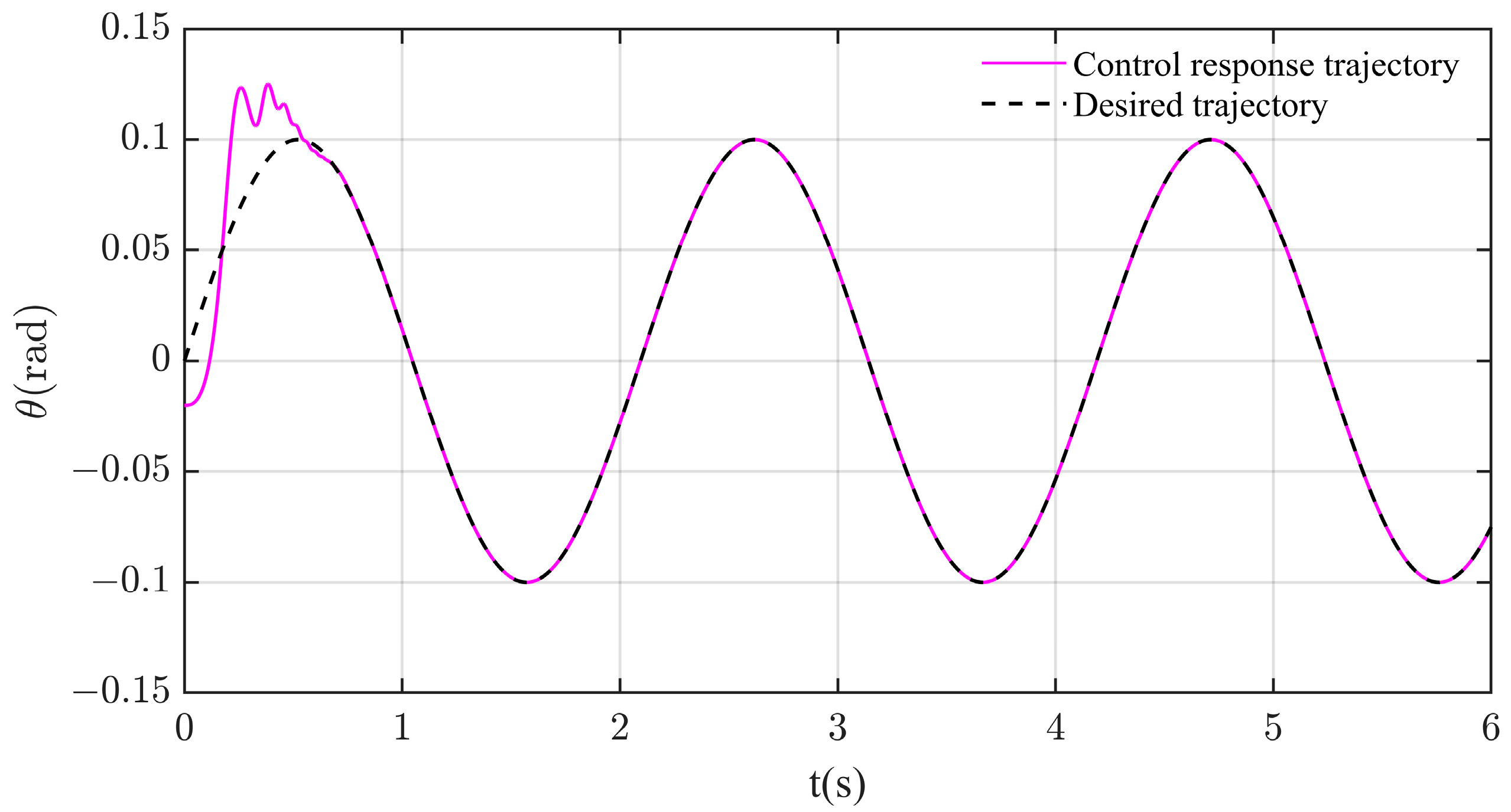
Figure 3 compares the calculated and desired pitch angles. After experiencing a slight fluctuation at the beginning of the quarter period, the calculated pitch angle trajectory almost overlaps with the expectations.
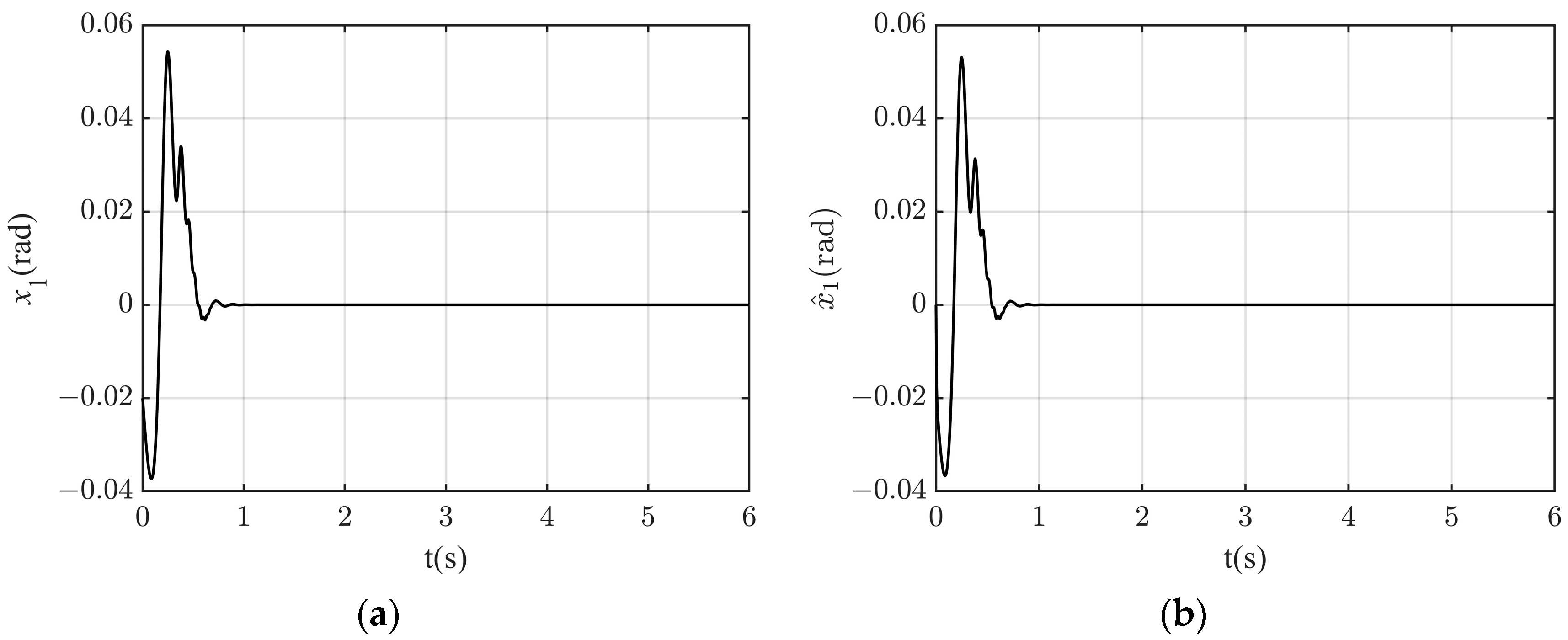
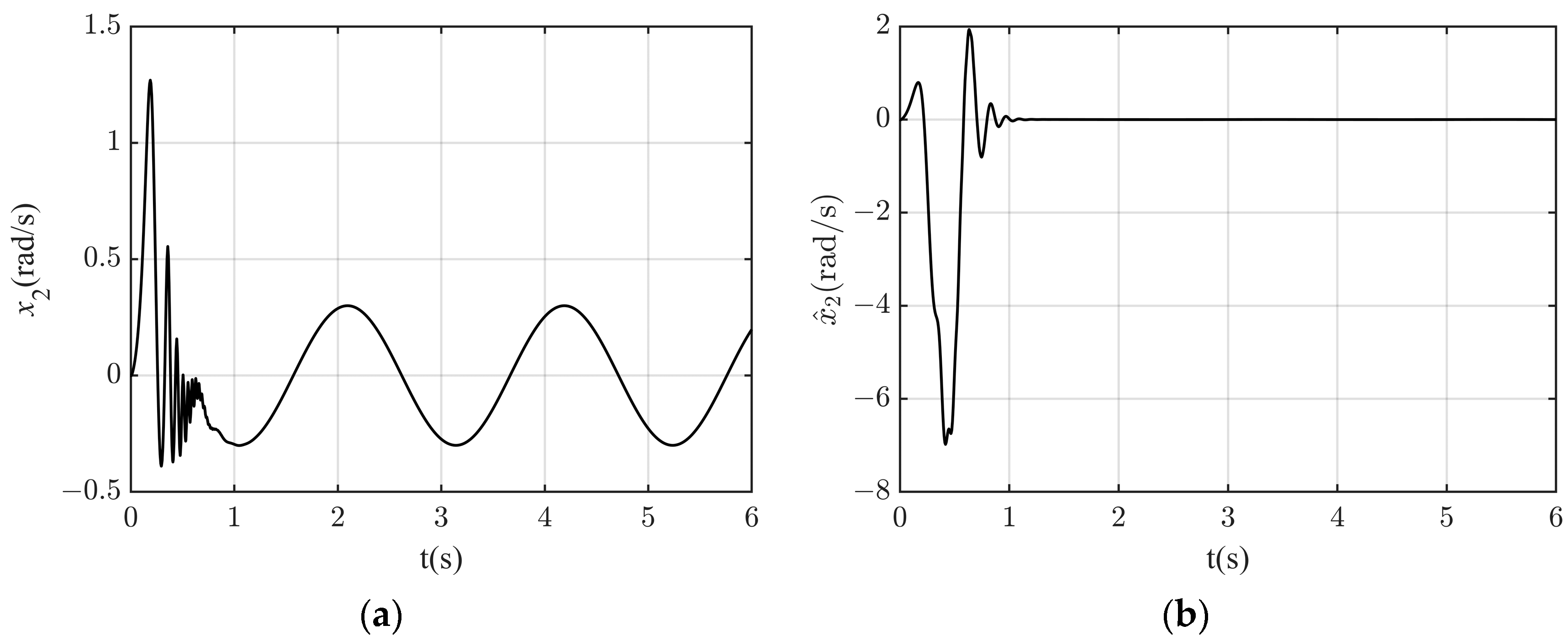
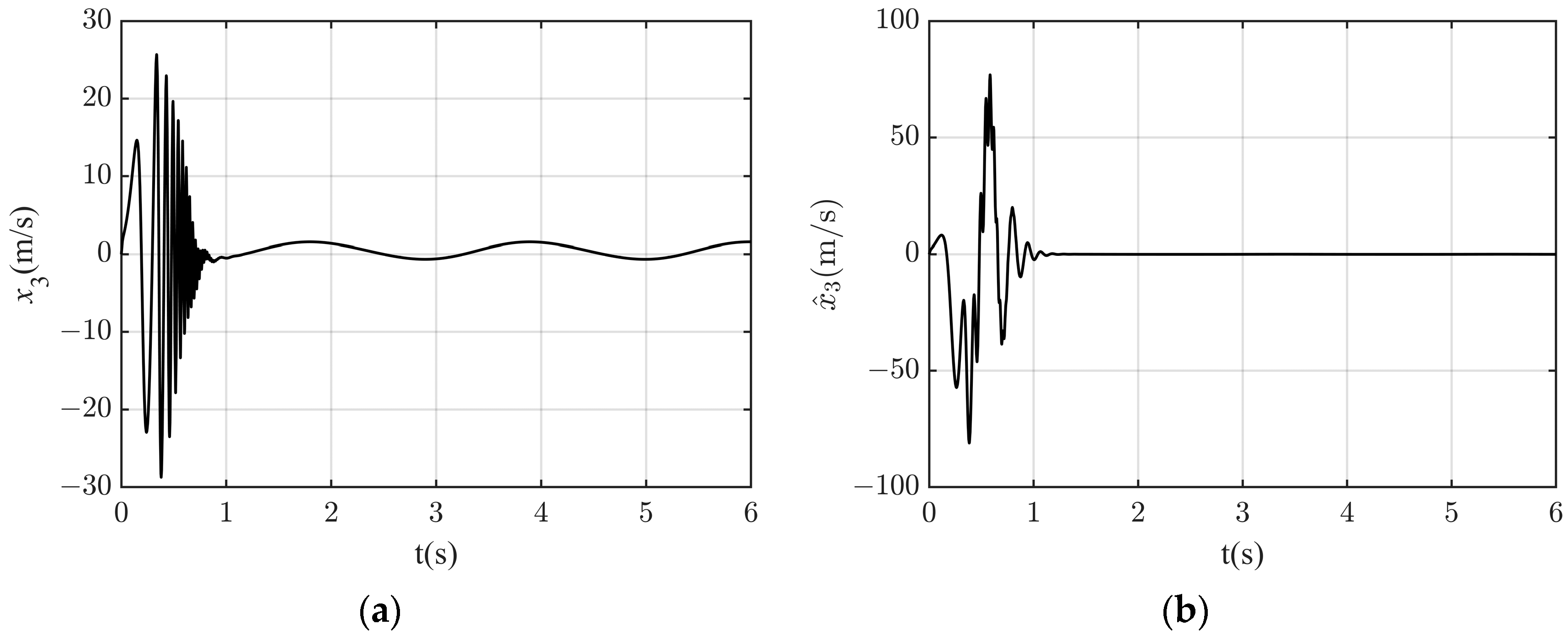
Figure 4, Figure 5 and Figure 6 show the trajectories of state variables x 1 (Figure 4a), x 2 (Figure 5a), and x 3 (Figure 6a), and their estimates x ^ 1 (Figure 4b), x ^ 2 (Figure 5b), and x ^ 3 (Figure 6b). In the system model, x 2 and x 3 are unmeasurable state variables. The controller performs indirect control through the observed quantities x ^ 2 and x ^ 3 without having direct control over these two quantities. Therefore, the actual values of x 2 and x 3 will exhibit some fluctuations, but this will not affect the control effect on the pitch angle. These estimated states are observed to remain within a finite range and exhibit a fast convergence to zero, achieved in about 1 s. This highlights the proposed control strategy’s rapid adaptability and stabilizing capabilities for high-order nonlinear systems and unmeasurable states. This fast stabilization ensures that the pitch angle can quickly track the expected trajectory.
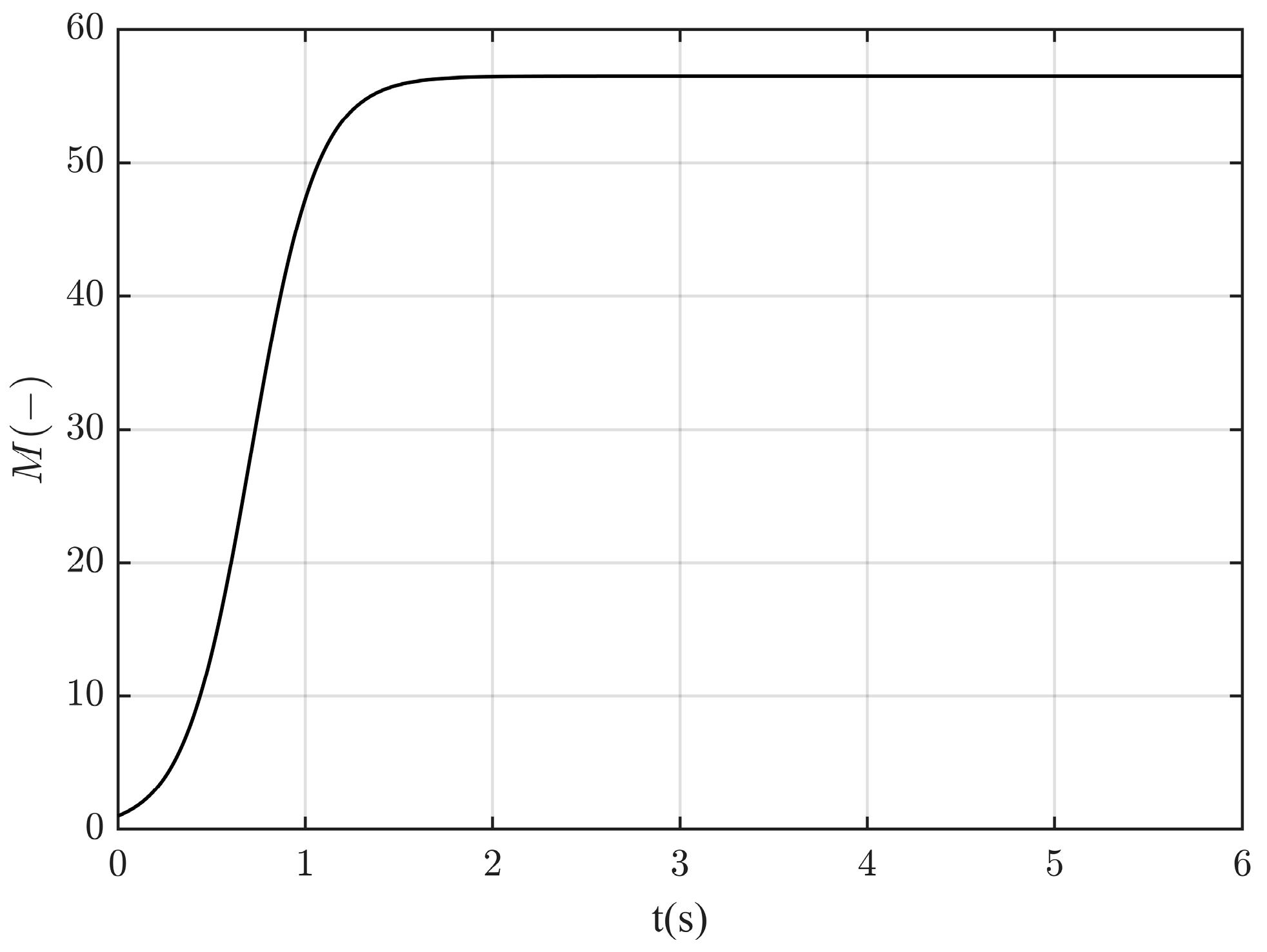
Figure 7 shows the temporal dynamic gain M. This stabilizes and becomes almost constant within the first 1.5 s, indicating that the system can rapidly handle the nonlinear growth conditions that are present. This rapid response enhances the observer’s measurement accuracy and accelerates the controller’s responses.
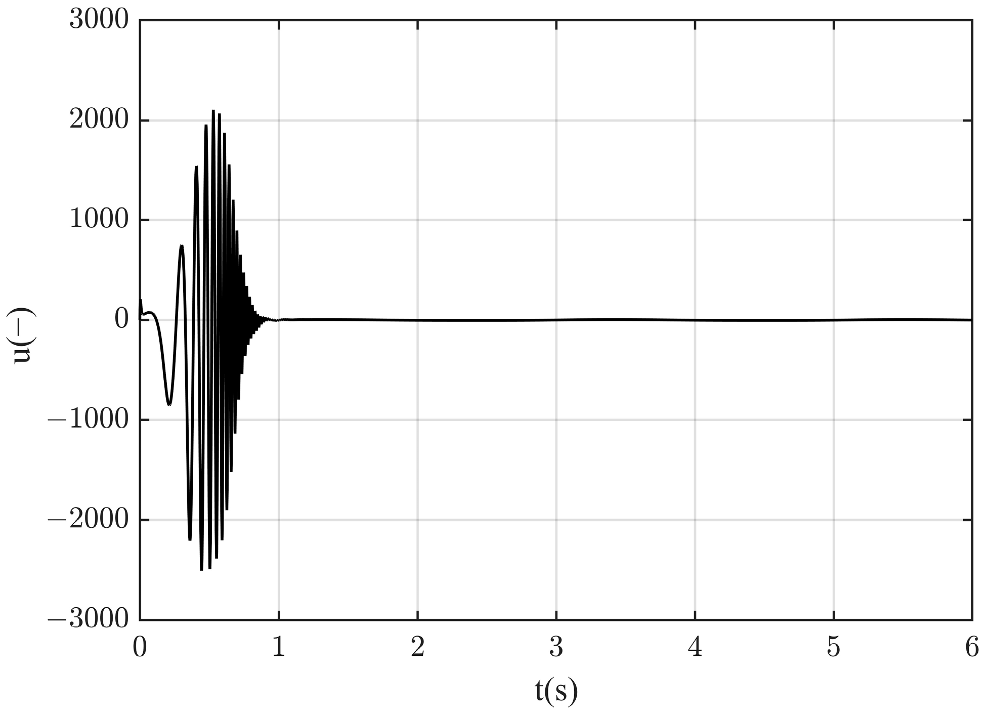
Figure 8 shows the trajectory of controller u , which becomes almost constant at the first 1 s. It is seen that the stabilization time for the dynamic gain M is longer in comparison with that of u , which might be attributed to the enhanced control effect obtained from the increased static gain L. The subsequent growth of the dynamic gain M after 1 s is intended to further reduce the tracking error.
Figure 9 illustrates the temporal tracking error of the proposed control algorithm. The tracking error, represented by θ y r t , fluctuates at the first 1 s within the range of (−0.04, 0.06) rad. After that, it rapidly decays to 10 6 rad and remains almost constant.
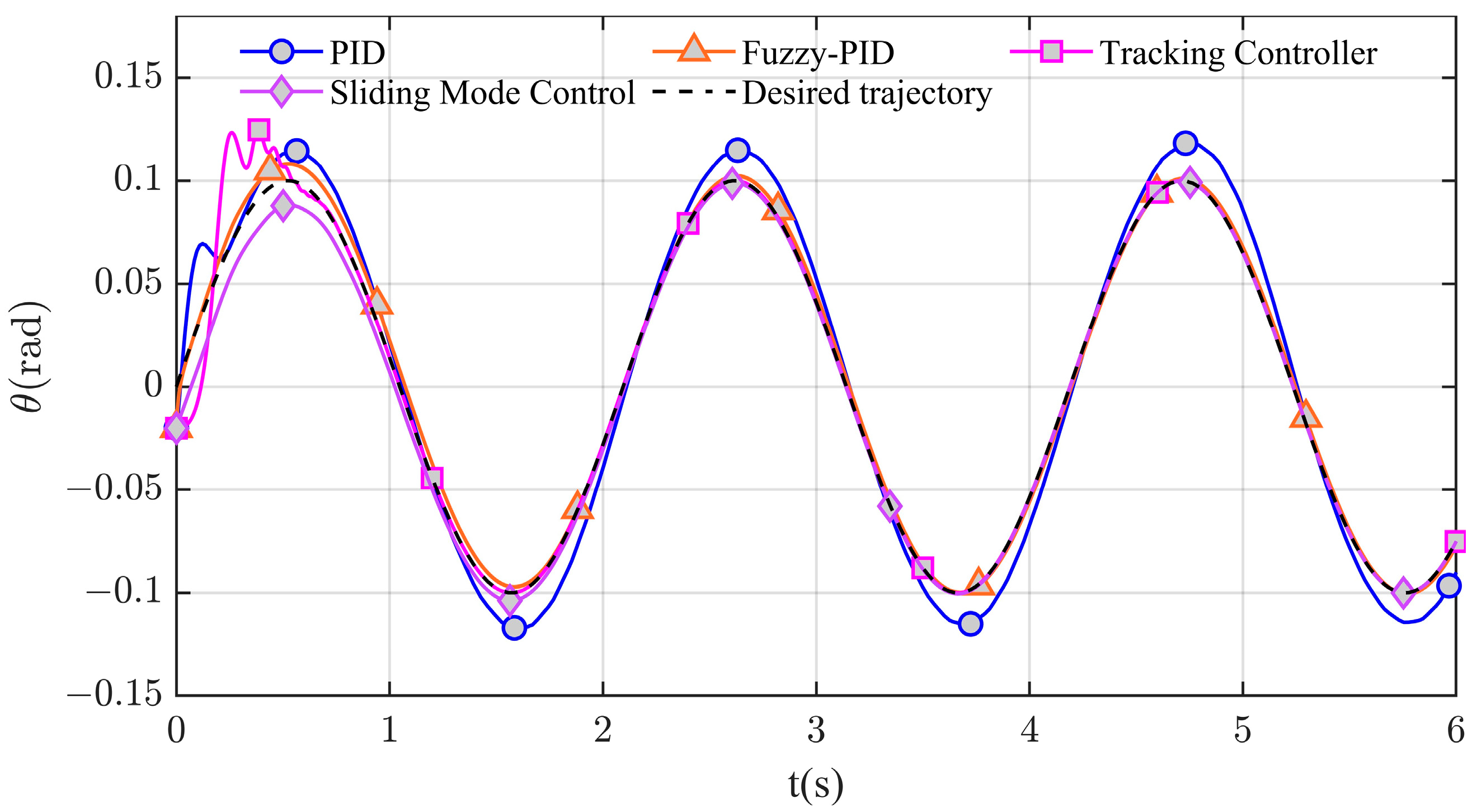
Figure 10 and Figure 11 compare the control performances of traditional PID and adaptive fuzzy PID controllers, the sliding mode controller, and the proposed tracking controller. Comparative analyses reveal that the fuzzy PID controller outperforms the traditional PID, which can be observed through the tracking errors shown in Figure 11. The enhanced performance is mainly attributed to the ability to handle the uncertainties and nonlinearities inherent in towed vehicle dynamics. It is important to note that both control strategies (PID and fuzzy PID) suffer increased challenges from higher-order nonlinearities. Traditional PID controllers, although robust, may struggle to provide a quick response to rapidly changing dynamics, leading to a longer settling time and a potential increase in steady-state errors. Using fuzzy PID, it is difficult to adjust the rule base and membership functions in real time when the parameters change rapidly and the uncertainty is too high. In contrast, sliding mode control demonstrates a better control performance, with both settling time and steady-state error being significantly smaller than those of the former two. When faced with large uncertainties, the sliding mode control law must gradually compensate for these unknowns. This process can slow down the system’s response, ultimately leading to an extended settling time. Compared with these three control methods, our proposed control strategy exhibits enhanced stability, reduced volatility, and superior adaptability to nonlinear dynamics.
Table 2 provides a quantitative analysis of the performance metrics of different control methods, and it can be seen that the control performance of PID and fuzzy PID is much weaker than that of sliding mode control and the tracking control proposed in this paper. Compared to the sliding mode control, the proposed control strategy showed a 74% improvement in setting time, and the steady-state error was enhanced from 10 6 to 10 8 . This is mainly attributed to the constructed high-gain state observer, which effectively manages the low-order polynomial growth in nonlinear systems. The dynamic gain parameters can be updated in real-time according to the control performance, while the static gain parameters were set to be as large as possible to meet the tracking error requirements, which also causes larger fluctuations before stabilization.

5. Conclusions

ROTV models possess nonlinear dynamic characteristics and uncertainties that include unmeasurable states. Traditional controllers struggle to achieve the desired control effects due to the oversimplifications of the system in linear models. This study introduces a pitch-control approach, employing dynamic and static gain observers to achieve the desired trajectories in the vertical pitch channel. The dynamics of the towed vehicle are decoupled into a nonlinear vertical pitch channel to accurately represent the state of the towed vehicle. A tracking control algorithm combining dynamic and static gains is then proposed based on the nominal model to mitigate issues arising from polynomial function growth. The efficiency and robustness of the proposed control algorithms are verified through numerical simulations. This approach enables the rapid achievement of the desired tracking trajectories, a reduction in control state errors, adaptation to nonlinear dynamics, and the effective suppression of uncertain disturbances.
At present, the proposed tracking control algorithm is in the theoretical stage, and its assumptions need to be further relaxed when applied to practical devices. In the next phase, we will further optimize the system model by incorporating the cable model into the towed vehicle, which will more accurately predict the coupling effects of the cable on the towed vehicle. Based on this, we can relax the conditions of the model assumptions, thereby enabling the proposed control methods to be applied to a broader range of scenarios. Furthermore, we will introduce depth tracking control to maintain the stable control of both the depth and pitch angle of the towed vehicle. For practical usages, the proposed pitch-tracking algorithms will be verified experimentally and then integrated into the controller of our ROTV system in the near future.

Author Contributions

Conceptualization, C.T., H.X., S.R., L.G., X.T. and J.W.; methodology, C.T., L.G., X.T. and J.W.; validation, C.T., S.R., X.T. and J.W.; formal analysis, C.T., S.R., X.T. and J.W.; investigation, C.T., H.X. and X.T.; resources, L.G., X.T. and J.W.; data curation, C.T., H.X., S.R., X.T. and J.W.; writing—original draft preparation, C.T.; writing—review and editing, C.T., S.R. and J.W.; visualization, C.T. and J.W.; supervision, X.T. and J.W.; project administration, X.T.; funding acquisition, X.T. and J.W. All authors have read and agreed to the published version of the manuscript.

Funding

This work was supported by the Fundamental Research Funds for the Provincial Universities of Zhejiang (No. GK229909299001-007); the open fund of State Key Laboratory of Satellite Ocean Environment Dynamics, Second Institute of Oceanography, MNR (No. QNHX2312), Key R & D Program of Zhejiang Province (No.2021C03013) and the Scientific Research Starting Fund from Hangzhou Dianzi University (GK239909299001-408, KYS045623025, KYS015624320).

Institutional Review Board Statement

Not applicable.

Informed Consent Statement

Not applicable.

Data Availability Statement

All data generated or analyzed during this research are included in this paper.

Conflicts of Interest

The authors declare no conflicts of interest.

Appendix A. Mathematical Characterization of Immeasurable States

Appendix A.1. System Representation

Consider a linear time-invariant system represented in the state-space form:
x ˙ t = A x t + B u t y t = C x t + D u t ,
where x t n is the state vector, u t m is the control input, and y t p is the output vector. The matrices A n × n ,   B n × m ,   C p × n , and D p × m describe the dynamics and output relationships of the system.

Appendix A.2. Observability

The system is said to be observable if the current state x t can be determined from the output y t over a finite time interval. The observability of the system is characterized by the observability matrix Z , presented as follows:
Z = C C A C A 2 C A n 1 p n × n .
If Z has full rank, i.e., rank ( Z ) = n, the system is fully observable. Otherwise, certain components of the state x t are immeasurable, and the system is said to be unobservable.

Appendix A.3. Luenberger Observer for State Estimation

In cases where not all states are directly measurable, a Luenberger observer can be designed to estimate the immeasurable states. The dynamics of the state estimate x ^ t are governed by the following:
x ^ ˙ t = A x ^ t + B u t + L y t C x ^ t ,
where x ^ t n is the estimated state vector, and L n × p is the observer gain matrix. The gain L is designed such that the estimation error e t = x t x ^ t converges to zero over time.

Appendix A.4. Unobservable Subspace

The unobservable subspace is the subspace of the state space that cannot be reconstructed from the system outputs. This subspace is defined as the null space of the observability matrix Z . Let N Z denote the null space of Z :
N Z = x n :   Z x = 0
States in this subspace are inherently immeasurable and cannot be estimated, regardless of the chosen observer or estimation strategy.

Appendix A.5. Controllability and Detectability

In addition to observability, controllability and detectability are crucial properties for understanding the behavior of immeasurable states. A system is controllable if it is possible to drive the state x t to any desired value through appropriate control inputs. Detectability, a weaker condition than observability, ensures that unobservable states are at least asymptotically stable.
The controllability matrix C is given by the following:
C = B A B A 2 B A n 1 B
A system is controllable if C has full rank.

Appendix A.6. Controllability and Detectability

The mathematical characterization of immeasurable states in control systems relies on the concepts of observability, state estimation, and the unobservable subspace. Estimation methods, such as the Luenberger observer, provide a means to infer immeasurable states, while the unobservable subspace defines the limitations of state estimation. Understanding these principles is critical for designing robust control strategies in systems with partially unmeasurable states.

References

  1. Karimi, H.R.; Lu, Y. Guidance and control methodologies for marine vehicles: A survey. Control Eng. Pract. 2021, 111, 104785. [Google Scholar] [CrossRef]
  2. Wang, N.; Xu, H.; Li, C.; Yin, J. Hierarchical Path Planning of Unmanned Surface Vehicles: A Fuzzy Artificial Potential Field Approach. Int. J. Fuzzy Syst. 2021, 23, 1797–1808. [Google Scholar] [CrossRef]
  3. Paley, D.A.; Zhang, F.; Leonard, N.E. Cooperative Control for Ocean Sampling: The Glider Coordinated Control System. IEEE Trans. Contr. Syst. Technol. 2008, 16, 735–744. [Google Scholar] [CrossRef]
  4. Xiang, G.; Xiang, X. 3D trajectory optimization of the slender body freely falling through water using cuckoo search algorithm. Ocean Eng. 2021, 235, 109354. [Google Scholar] [CrossRef]
  5. Peng, Z.; Wang, J.; Wang, D.; Han, Q.-L. An Overview of Recent Advances in Coordinated Control of Multiple Autonomous Surface Vehicles. IEEE Trans. Ind. Inf. 2021, 17, 732–745. [Google Scholar] [CrossRef]
  6. Zhang, Q.; Zhang, J.; Chemori, A.; Xiang, X. Virtual Submerged Floating Operational System for Robotic Manipulation. Complexity 2018, 2018, 9528313. [Google Scholar] [CrossRef]
  7. Hashimoto, K.; Watanabe, M.; Tashiro, S.; Momma, H. Missing of the ROV kaiko vehicle -problem on the secondary cable. In Proceedings of the Oceans ’04 MTS/IEEE Techno-Ocean ’04 (IEEE Cat. No.04CH37600), Kobe, Japan, 9–12 November 2004; IEEE: Kobe, Japan, 2004; Volume 2, pp. 807–811. [Google Scholar]
  8. Gatto, A.; Sadik-Zada, E.R.; Özbek, S.; Kieu, H.; Nguyen Huynh, N.T. Deep-sea fisheries as resilient bioeconomic systems for food and nutrition security and sustainable development. Resour. Conserv. Recycl. 2023, 197, 106907. [Google Scholar] [CrossRef]
  9. Lembke, C.; Grasty, S.; Silverman, A.; Broadbent, H.; Butcher, S.; Murawski, S. The Camera-Based Assessment Survey System (C-BASS): A towed camera platform for reef fish abundance surveys and benthic habitat characterization in the Gulf of Mexico. Cont. Shelf Res. 2017, 151, 62–71. [Google Scholar] [CrossRef]
  10. Liu, H.; Wang, Z.; Shan, R.; He, K.; Zhao, S. Research into the integrated navigation of a deep-sea towed vehicle with USBL/DVL and pressure gauge. Appl. Acoust. 2020, 159, 107052. [Google Scholar] [CrossRef]
  11. Lock, A.; Spiers, G.; Hostetler, B.; Ray, J.; Wallschläger, D. Multi-dimensional water quality assessment of an urban drinking water source elucidated by high resolution underwater towed vehicle mapping. Water Res. 2016, 93, 289–295. [Google Scholar] [CrossRef]
  12. Wang, M.; Deng, M.; Wu, Z.; Luo, X.; Jing, J.; Chen, K. The deep-tow marine controlled-source electromagnetic transmitter system for gas hydrate exploration. J. Appl. Geophys. 2017, 137, 138–144. [Google Scholar] [CrossRef]
  13. Park, J.; Rhee, S.H.; Im, J.-B.; Ji, B.H.; Lee, S.J. Experimental study on the towing stability of a towed underwater object. Int. J. Nav. Archit. Ocean Eng. 2023, 15, 100539. [Google Scholar] [CrossRef]
  14. Kim, H.-G.; Yun, S.-J.; Park, J.-W.; Lee, H.-J.; Hwang, J.-H.; Kim, J.-C.; Choi, Y.-H.; Ryu, J.-K.; Suh, J.-H. Estimation and Control of a Towed Underwater Vehicle with Active Stationary and Low-Speed Maneuvering Capabilities. JMSE 2023, 11, 1176. [Google Scholar] [CrossRef]
  15. Zhang, B.; Ji, D.; Liu, S.; Zhu, X.; Xu, W. Autonomous Underwater Vehicle navigation: A review. Ocean Eng. 2023, 273, 113861. [Google Scholar] [CrossRef]
  16. He, Y.; Wang, D.B.; Ali, Z.A. A review of different designs and control models of remotely operated underwater vehicle. Meas. Control 2020, 53, 1561–1570. [Google Scholar] [CrossRef]
  17. Hutapea, F.L.; Tsuji, T.; Katou, M.; Asakawa, E. Data processing and interpretation schemes for a deep-towed high-frequency seismic system for gas and hydrate exploration. J. Nat. Gas Sci. Eng. 2020, 83, 103573. [Google Scholar] [CrossRef]
  18. Li, Y.; Zhao, S.; Setiawan, L.; Zhang, L.; Wang, R. Integral hollow fiber membrane with chemical cross-linking for pressure retarded osmosis operated in the orientation of active layer facing feed solution. J. Membr. Sci. 2018, 550, 163–172. [Google Scholar] [CrossRef]
  19. Li, B.; Huang, W.; Liang, H. An efficient method to assess effect of fin on the course stability of towing system. Ocean Eng. 2020, 217, 108005. [Google Scholar] [CrossRef]
  20. Li, Z.; Chen, Y.; Chen, H.; Sun, Z.; Ye, X.; Xue, G. Hydrodynamic performance optimization and adjustment prediction of a novel deep-sea towed body with adjustable hydrofoils. Ocean Eng. 2024, 296, 116937. [Google Scholar] [CrossRef]
  21. Wang, M.; Pang, S.; Jin, K.; Liang, X.; Wang, H.; Yi, H. Construction and experimental verification research of a magnetic detection system for submarine pipelines based on a two-part towed platform. J. Ocean Eng. Sci. 2023, 8, 169–180. [Google Scholar] [CrossRef]
  22. Guo, L.; Yuan, Y.; Tang, W.; Xue, H. A numerical investigation on quasi-static configuration and nonlinear dynamic response characteristics of marine towing cable. Ocean Eng. 2021, 240, 110007. [Google Scholar] [CrossRef]
  23. Yang, X.; Wu, J.; Li, Q.; Lv, H. Numerical Simulation of Depth Tracking Control of an Underwater Towed System Coupled with Wave–Ship Interference. JMSE 2021, 9, 874. [Google Scholar] [CrossRef]
  24. Xin, X. Linear strong structural controllability and observability of an n -link underactuated revolute planar robot with active intermediate joint or joints. Automatica 2018, 94, 436–442. [Google Scholar] [CrossRef]
  25. Jia, J.; Trentelman, H.L.; Baar, W.; Camlibel, M.K. A Sufficient Condition for Colored Strong Structural Controllability of Networks. IFAC-Pap. 2018, 51, 16–21. [Google Scholar] [CrossRef]
  26. Pequito, S.; Popli, N.; Kar, S.; Ilic, M.D.; Aguiar, A.P. A framework for actuator placement in large scale power systems: Minimal strong structural controllability. In Proceedings of the 2013 5th IEEE International Workshop on Computational Advances in Multi-Sensor Adaptive Processing (CAMSAP), St. Martin, France, 15–18 December 2013; IEEE: St. Martin, France, 2013; pp. 416–419. [Google Scholar]
  27. Weber, A.; Reissig, G.; Svaricek, F. A linear time algorithm to verify strong structural controllability. In Proceedings of the 53rd IEEE Conference on Decision and Control, Los Angeles, CA, USA, 15–17 December 2014; IEEE: Los Angeles, CA, USA, 2014; pp. 5574–5580. [Google Scholar]
  28. Jarczyk, J.C.; Svaricek, F.; Alt, B. Strong structural controllability of linear systems revisited. In Proceedings of the IEEE Conference on Decision and Control and European Control Conference, Orlando, FL, USA, 12–15 December 2011; IEEE: Orlando, FL, USA, 2011; pp. 1213–1218. [Google Scholar]
  29. Liu, C.; Li, J.; Yang, S.; Xiang, X. Simultaneously Tracking and Pitch Control of Underwater Towed Vehicle with Multiple Elevators: A Finite-Time Fuzzy Approach. Int. J. Fuzzy Syst. 2023, 25, 264–274. [Google Scholar] [CrossRef]
  30. Minowa, A.; Toda, M. A High-Gain Observer-Based Approach to Robust Motion Control of Towed Underwater Vehicles. IEEE J. Ocean. Eng. 2019, 44, 997–1010. [Google Scholar] [CrossRef]
  31. Su, Z.; Li, C.; Zhen, Z. Anti-disturbance constrained control of the air recovery carrier via an integral barrier Lyapunov function. Aerosp. Sci. Technol. 2020, 106, 106157. [Google Scholar] [CrossRef]
  32. Krishnamurthy, P.; Khorrami, F. Feedforward Systems With ISS Appended Dynamics: Adaptive Output-Feedback Stabilization and Disturbance Attenuation. IEEE Trans. Automat. Contr. 2008, 53, 405–412. [Google Scholar] [CrossRef]
  33. Curado Teixeira, F.; Pedro Aguiar, A.; Pascoal, A. Nonlinear adaptive control of an underwater towed vehicle. Ocean Eng. 2010, 37, 1193–1220. [Google Scholar] [CrossRef]
  34. Benazouz, R.; Chemori, A.; Creuze, V. A novel intelligent RISE feedback control of autonomous tethered underwater vehicles: Design & real-time experiments. Ocean Eng. 2024, 300, 117470. [Google Scholar]
  35. Tabataba’i-Nasab, F.S.; Keymasi Khalaji, A.; Moosavian, S.A.A. Adaptive nonlinear control of an autonomous underwater vehicle. Trans. Inst. Meas. Control 2019, 41, 3121–3131. [Google Scholar] [CrossRef]
  36. Zhang, J.; Yu, S.; Yan, Y. Fixed-time extended state observer-based trajectory tracking and point stabilization control for marine surface vessels with uncertainties and disturbances. Ocean Eng. 2019, 186, 106109. [Google Scholar] [CrossRef]
  37. Sun, H.; Zong, G.; Cui, J.; Shi, K. Fixed-time sliding mode output feedback tracking control for autonomous underwater vehicle with prescribed performance constraint. Ocean Eng. 2022, 247, 110673. [Google Scholar] [CrossRef]
  38. Shi, Y.; Xie, W.; Chen, W.; Xing, L.; Zhang, W. Neural Adaptive Intermittent Output Feedback Control for Autonomous Underwater Vehicles With Full-State Quantitative Designs. IEEE Trans. Neural Netw. Learn. Syst. 2023, 35, 12836–12848. [Google Scholar] [CrossRef]
  39. Shang, F.; Liu, Y.; Zhang, C. Adaptive practical tracking control by output feedback for a class of nonlinear systems. J. Syst. Sci. Complex. 2010, 23, 1210–1220. [Google Scholar] [CrossRef]
  40. Wu, G.; Li, L.-S.; Miao, X.-F.; Cong, X.-R. Luenberger-Type Observer Design for Stochastic Time-Delay Systems. Int. J. Theor. Phys. 2013, 52, 2065–2074. [Google Scholar] [CrossRef]
  41. Praly, L.; Jiang, Z.P. Linear output feedback with dynamic high gain for nonlinear systems. Syst. Control. Lett. 2004, 53, 107–116. [Google Scholar] [CrossRef]
Figure 1. Schematic diagram of the ROTV.
Jmse 12 01953 g001
Figure 2. Pitch-control framework based on the dynamic and static gain algorithm.
Jmse 12 01953 g002
Figure 3. The trajectories of controlled and desired responses.
Jmse 12 01953 g003
Figure 4. The trajectories of x 1 and x ^ 1 . (a) The trajectory of state   x 1 ; (b) the trajectory of observed state x ^ 1 .
Jmse 12 01953 g004
Figure 5. The trajectories of x 2 and x ^ 2 . (a) The trajectory of state   x 2 ; (b) the trajectory of observed state x ^ 2 .
Jmse 12 01953 g005
Figure 6. The trajectories of x 3 and x ^ 3 . (a) The trajectory of state   x 3 ; (b) the trajectory of observed state x ^ 3 .
Jmse 12 01953 g006
Figure 7. The trajectory of dynamic gain M .
Jmse 12 01953 g007
Figure 8. The trajectory of controller u .
Jmse 12 01953 g008
Figure 9. The trajectory error of y .
Jmse 12 01953 g009
Figure 10. The trajectories of pitch angle simulated by PID, fuzzy PID, sliding mode control, proposed tracking controllers, and desired outcome.
Jmse 12 01953 g010
Figure 11. Pitch error comparisons between PID, fuzzy PID, sliding mode control and proposed tracking controllers.
Jmse 12 01953 g011
Table 1. Design parameters of the tracking control algorithm.
Design ParametersSymbolValue
Static gain L 0 ,   18
Dynamic gain parameters p 60
β 1 0.1
β 2 5.65
State observer parameters l 1 40
l 2 3
l 3 1
Controller parameters k 1 80
k 2 10
k 3 80
Table 2. Quantitative performance indicators of different control methods.
Control MethodSettling TimePeak ValueSteady-State Error
PID-0.037 rad0.016 rad
Fuzzy PID-0.010 rad0.002 rad
Sliding Mode
Control
3.5 s0.021 rad 10 6 rad
Tracking Controller0.9 s0.054 rad 10 8 rad
Disclaimer/Publisher’s Note: The statements, opinions and data contained in all publications are solely those of the individual author(s) and contributor(s) and not of MDPI and/or the editor(s). MDPI and/or the editor(s) disclaim responsibility for any injury to people or property resulting from any ideas, methods, instructions or products referred to in the content.