Article

Experimental Investigation on Wave Dissipation of Perforated Pipe Breakwater Under Regular Wave Conditions

1
College of Ocean Science and Engineering, Shandong University of Science and Technology, Qingdao 266590, China
2
Hubei Key Laboratory of Marine Geological Resources, China University of Geosciences, Wuhan 430074, China
3
Key Laboratory of Marine Intelligent Equipment and System of the Ministry of Education, State Key Laboratory of Ocean Engineering, School of Ocean and Civil Engineering, Shanghai Jiao Tong University, Shanghai 200240, China
4
Qingdao Municipal Transport Development Centre, Qingdao 266100, China
5
College of Engineering, Ocean University of China, Qingdao 266100, China
6
Dalian Haiyang Fishery Engineering Planning, Design and Research Co., Ltd., Dalian 116000, China
7
Faculty of Engineering and Digital Technologies, University of Bradford, Bradford BD7 1DP, UK
*
Author to whom correspondence should be addressed.
J. Mar. Sci. Eng. 2024, 12(12), 2137; https://doi.org/10.3390/jmse12122137 (registering DOI)
Submission received: 16 September 2024 / Revised: 11 November 2024 / Accepted: 21 November 2024 / Published: 23 November 2024
(This article belongs to the Section Ocean Engineering)

Abstract

:
The permeable breakwater is an innovative, eco-friendly coastal protection structure that reduces wave impact while minimizing “dead water” and environmental harm. This study introduces a perforated pipe breakwater design with an increasing pipe diameter from top to bottom, evaluated through physical model tests using transmission coefficient Kt and reflection coefficient Kr serving as the primary parameters. The results indicate that Kt decreases as the relative width (B/L), wave steepness (H/L), and relative water depth (h/L) increase, but rises with a steeper breakwater slope. When B/L exceeds 0.3, H/L surpasses 0.06, or the h/L ratio is greater than 0.3, Kt gradually declines until reaching a stable state, resulting in a more pronounced wave reduction. As B/L and H/L increase, the coefficient Kr initially drops, then rises. The slope ratio of 1:1.5 demonstrates the most effective wave energy dissipation, with primary dissipation occurring on the front slope. The mixed pipe diameter design shows superior wave absorption over a uniform diameter. Compared to a porous horizontal plate, the perforated pipe breakwater exhibits better wave absorption. These findings offer valuable guidance for designing eco-friendly coastal protection projects.

1. Introduction

Breakwater is an essential component of coastal port protection systems, serving multiple functions. They defend against wave and ice impacts, prevent sediment from entering the port, reduce siltation, and ensure water stability. Additionally, they provide stable and secure conditions for ship berthing and operations [1]. However, traditional impermeable breakwaters disrupt water flow, sediment dynamics, and water quality in the surrounding sea. This disruption can upset the natural balance between erosion and deposition, alter seabed sedimentation patterns, influence topographic evolution, and even harm marine benthic habitats [2].
To address these limitations, an eco-friendly solution known as the permeable breakwater has been developed. This structure not only meets wave resistance requirements but also minimizes negative effects on marine ecosystems. Consequently, permeable energy dissipating structures have been widely used in environmentally sensitive areas [3]. Over time, various designs have emerged, including structures with pipes, single and double-baffle pile foundations, vertical and curved baffles, multilayer perforated baffles, and pile rows. These different types exhibit varying wave absorption capabilities, prompting extensive research. Among the key indicators used to evaluate wave absorption are the transmission and reflection coefficients.
The concept of the permeable breakwater was first proposed by Weigel, who derived analytical solutions for the reflection and transmission coefficients of vertical baffle breakwaters, although the influence of wave diffraction was not considered [4]. Building on Weigel’s work, Cмиphob introduced a local loss resistance coefficient, modified the formulas, and established conditions for their application [5]. Hou proposed a permeable pipe breakwater design consisting primarily of prefabricated pipes with circular sections (see Figure 1). This design minimizes wave pressure on its surface, resulting in high stability [6]. Using wave theory, Li et al. and Shi et al. developed formulas for calculating reflection and transmission coefficients, as well as wave pressure and pressure spectra, for tubular permeable levees interacting with regular waves [7,8,9]. Through various theoretical approaches, Qiu et al. and Ju et al. derived analytical solutions for the transmission and reflection coefficients of single-layer baffle-permeable breakwaters, laying a theoretical foundation for subsequent studies on plate breakwaters [10,11]. Zhu investigated wave reduction and stress characteristics of single-layer vertical baffle breakwaters while considering fluid viscosity [12].
Yin, Fan, and Shao derived formulas for calculating transmission coefficients for tubular permeable breakwaters, single-layer vertical baffle breakwaters, double-sided baffle permeable breakwaters, and vertical baffle permeable breakwaters through model testing [13,14,15]. Syamsuri et al. discovered that the transmitted wave height of porous breakwater decreases as the roughness of the pipe wall increases, while the reflected wave height increases with an increase in pipe wall roughness [16]. Wang studied the wave absorption performance of single-layer horizontal and arc slab breakwaters with different openings, finding that submerged arc plates significantly enhance energy dissipation [17]. Neelamani et al. demonstrated that a double-layer plate structure, compared to a single-layer design, more effectively reduces wave transmission and improves wave protection. They also introduced T-type and ⊥-type breakwaters, with physical model tests indicating that T-type breakwaters offer better wave transmission reduction and increased reflection [18,19,20]. Tao et al. further introduced a + type breakwater, combining features of T-type and ⊥-type permeable breakwaters, and evaluated its wave dissipation performance through physical model testing [21].
For a multilayer horizontal-plate permeable breakwater, Wang suggested that the relative width is the primary factor influencing wave absorption performance [22]. In contrast, Yan et al. argued that for a multilayer baffle-permeable breakwater, the permeability and opening mode of the baffle are the key factors affecting wave reduction [23]. Similarly, Wang et al. studied the impact of the opening rate and layout of wave baffles on the wave dissipation performance of an inclined wave baffle pile-foundation permeable breakwater. They found that the reflection coefficient was determined by the opening rate of the front-row wave baffles, while the transmission coefficient depended on the minimum opening rate of the wave baffles [24]. Teh et al. found that an open semicircular breakwater with slit baffles showed superior wave dissipation performance, especially when using double-slit baffles and achieving a porosity of 25% [25]. He et al. argued that wave energy utilization breakwaters offer better wave protection compared to pile foundation breakwaters [26,27]. Yu et al. proposed a formula for calculating the horizontal wave pressure on permeable breakwater based on model tests [28]. Lu et al. identified relative wave height as the primary factor influencing surface wave pressure and structural force in a new perforated I-plate breakwater design [29]. Meanwhile, He et al. maintained that a labyrinth-type permeable breakwater with a cross-shaped wave-absorbing structure provided enhanced protection against low tide and high waves, demonstrating excellent transmission and reflection characteristics [30].
Yu et al., Pan, Zhao et al., and Wang examined the wave absorption performance of curved permeable breakwaters under various conditions. Their findings indicated that curved permeable breakwaters exhibited superior wave absorption compared to vertical plate permeable breakwaters, horizontal plate permeable breakwaters, and vertical breakwaters under the same conditions [31,32,33,34]. Yagci et al. studied the dynamic pressure distribution on inclined piles and the surrounding areas under the influence of regular and irregular waves [35]. Rao et al. conducted physical model tests to assess the hydrodynamic characteristics of submerged inclined-plate structures [36]. Wang et al. and Fan et al. found that inclined plates with open holes had better wave dissipation performance than flat plates with open holes, particularly when the inclination angle was set to 15° [37,38].
Tang et al. performed a comprehensive analysis of the wave absorption effect and stress distribution in a new permeable composite plate breakwater featuring both open baffles and open horizontal plates. The results showed significant improvements in wave absorption and stress distribution compared to a single-plate structure [39]. Guo et al. thoroughly investigated the influence of design parameters and wave characteristics on the reflection, transmission, and dissipation coefficients of a new flexible membrane breakwater under both regular and irregular wave conditions. They found that while the overall trends of transmission and dissipation coefficients were similar for regular and irregular waves, the reflection coefficient showed periodic fluctuations in regular waves, a phenomenon not observed in irregular waves [40,41]. The research findings of the aforementioned scholars show the ongoing optimization of wave dissipation structures in permeable breakwaters. The use of porous, double-layer, and multilayer wave-absorbing structures has resulted in complex interactions between waves and breakwaters. With advances in computing power, numerical simulation methods have become effective for analyzing the hydrodynamics of these complex structures, providing guidance for accurate calculations related to breakwater designs.
Zhu et al. employed numerical methods to simulate the effects of various factors, including the relative width of the top of the embankment, relative water depth, and relative wave height, on the transmission coefficient of a high-pile baffle permeable breakwater under regular wave conditions. They also proposed a correction formula [42]. Yu et al. investigated the wave-absorbing performance, load characteristics, and other hydrodynamic properties of an anti-silting permeable breakwater under regular wave action by developing a numerical model. They found that the transmission coefficient significantly decreased as the baffle depth increased [43,44]. Sundar et al. examined the impact of the clearance ratio and relative draft of a right-angled fan-shaped pile breakwater on transmission and reflection characteristics [45].
Du et al. proposed two novel breakwater designs incorporating wave channels and conducted a comparative analysis of transmission coefficient variations under different wave characteristics and structural parameters [46]. Wu et al. found that a curved plate structure exhibited better wave dissipation performance than a horizontal plate structure [47]. Wang et al. introduced an anti-wave arc design for a pontoon-type breakwater, which resulted in enhanced wave dissipation [48]. Cho and Kim studied the wave dissipation effects of horizontal, inclined, and double-layer porous breakwaters against oblique incident waves using numerical simulations based on potential flow theory and Darcy’s law [49]. Gayen and Mondal analyzed the wave dissipation performance of a vertically symmetrical double-inclined plate breakwater using numerical simulations in the vertical wave direction. Their results showed that the reflection coefficient of two symmetric inclined plates was higher than that of one inclined plate but lower than that of two vertical plates [50]. Cheng investigated the wave–structure interaction of a porous Type I composite (PITC) breakwater using a numerical flume and found that the hydrodynamic behavior of the breakwater was significantly affected by the relative submerged depth (h/d). Greater relative depth led to increased wave energy dissipation and improved wave absorption [51].
In conclusion, extensive research has been conducted on the wave dissipation characteristics of various permeable breakwaters, yielding valuable insights. However, there is still a noticeable gap in studies specifically focusing on permeable pipe breakwaters, with no research reporting on the wave dissipation characteristics of combined pipe diameter permeable breakwaters. To address this gap, the present study proposes a new type of combined pipe permeable breakwater based on features introduced by Hou [6]. The wave-absorbing performance of different structural types of permeable pipe breakwaters was evaluated through physical model testing, examining the variations in transmission and reflection coefficients concerning top width, slope angle, pipe diameter, wave steepness, and relative water depth. Additionally, the study compared the wave absorption effects of permeable and horizontal plate breakwaters. These findings provide valuable references for engineering designs involving permeable breakwaters. The remainder of this paper is organized as follows: Section 2 provides a detailed overview of the experiment, including the perforated pipe breakwater model, experimental setup, scheme, and grouping. In Section 3, we present the experimental results and discuss the effects of various factors on the performance of porous pipe breakwaters. Finally, Section 4 summarizes the study’s conclusions and outlines directions for future research.

2. Physical Model Tests

The physical model tests were conducted in a wave–current circulation flume at the Ocean University of China’s hydrodynamics laboratory. The flume measures 30 m in length, 0.6 m in width, and 0.8 m in depth, with a water depth consistently maintained at 0.4 m during the experiments. It is equipped with a wave paddle at one end and an energy dissipation facility at the other. The transmission and reflection coefficients of the breakwater were analyzed using the Goda two-point method, which involves placing two measurement points along the wave propagation direction and recording waveform changes. The Fourier series method was then used to separate and calculate the overall reflection coefficient and the amplitudes of wave components at different frequency intervals for both incident and reflected waves. Five wave altimeters were strategically placed within the flume, as shown in Figure 2. According to the wave model test regulations [52], the physical model tests ensured geometric and gravitational similarity while disregarding mass and center of gravity similarity. A normal model scale of λL = 40 was used to analyze the interaction between waves and models. The study investigated how different breakwater structural parameters and wave characteristics influenced the transmission and reflection coefficients under regular wave conditions. Before conducting the experiments, the wave height meter was calibrated to eliminate potential system errors.
Based on relevant research parameters from Hou [6] (with a pipe outer diameter D of 1.8 m and inner diameter d of 1.0 m), a PVC pipe was chosen for constructing the permeable pipe breakwater model due to its high strength and compressive properties. The pipe diameter increased gradually from top to bottom. PVC adhesive was used to secure the pipes, while screws provided additional reinforcement at three points between pipes of different diameters, as shown in Figure 3a. The model’s dimensions ranged from 0.2 to 2.1 m in length and 0.6 m in width. The length varied according to changes in the top width and slope of the breakwater, while the height was determined by the pipe diameter for different breakwater structures. The tests included three distinct structural configurations: the first consisted of pipe diameters of 32 mm for layers 1–4, 50 mm for layers 5–7, 75 mm for layers 8–9, and 110 mm for layer 10. In the second configuration, the upper pipe diameter was fixed at 32 mm from layers 1 to 7, while it remained the same as the first configuration from layers 8 to 10. Specifically, the pipe diameter was set to 75 mm for layers 8 and 9, and it was increased to 110 mm for the 10th floor. For the third configuration, the pipe diameter was adjusted to be 50 mm from layers 1 to 7, whereas from layer 8 to layer 9, it remains unchanged compared with that in the first configuration. To ensure model height accuracy, it was necessary to remove the PVC pipe from the 10th layer. A double horizontal plate of breakwater with a width of 40 cm and a height of 50 cm was used for comparison. The distance between the two horizontal plates matched the height of layers 1 to 4 in the permeable pipe, as shown in Figure 3b. The experimental groups are presented in Table 1.

3. Results and Discussion

3.1. The Relative Top Width of the Breakwater (B/L)

In this study, the relative top width of the breakwater was defined as the ratio between the top width (B) and the wavelength (L). The transmission coefficient Kt represents the ratio of the stable transmitted wave height (H1) behind the breakwater to the incident wave height (H) in front of it.
K t = H 1 H
The wave reflection coefficient Kr denotes the ratio of the height of the reflected wave (Hr) to the height of the incident wave (H).
K r = H r H
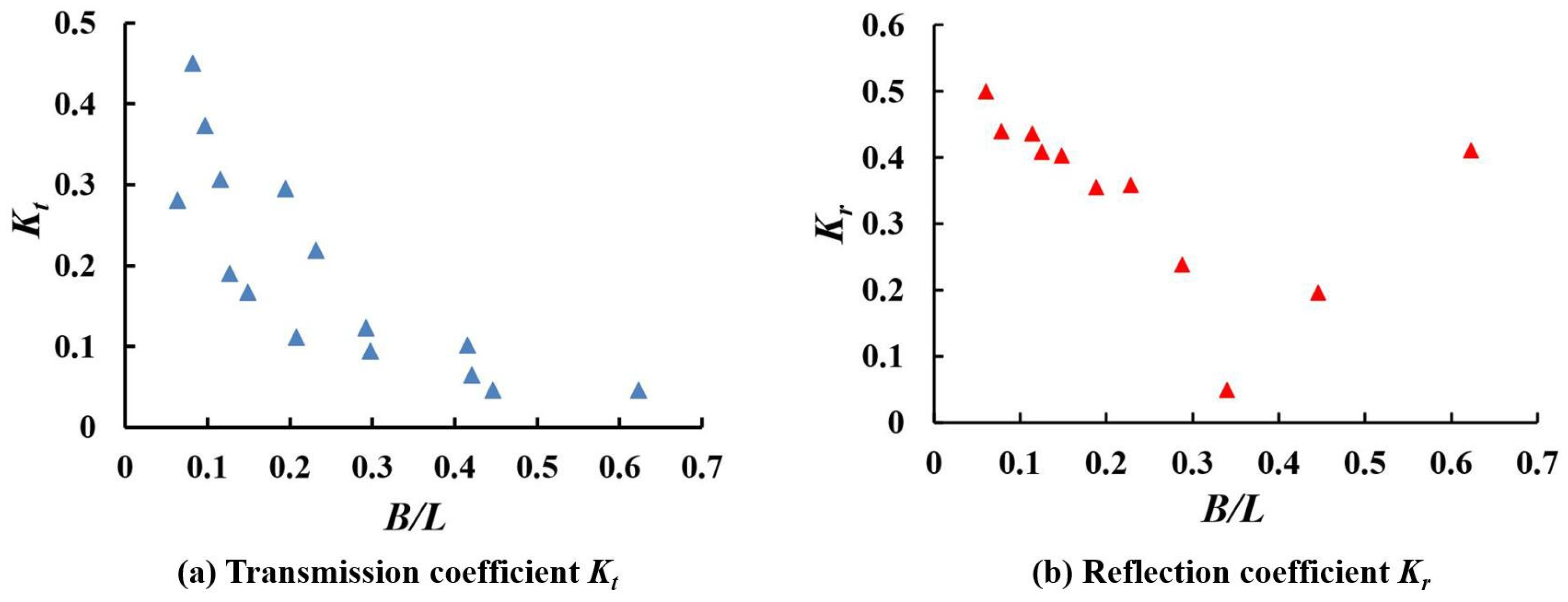
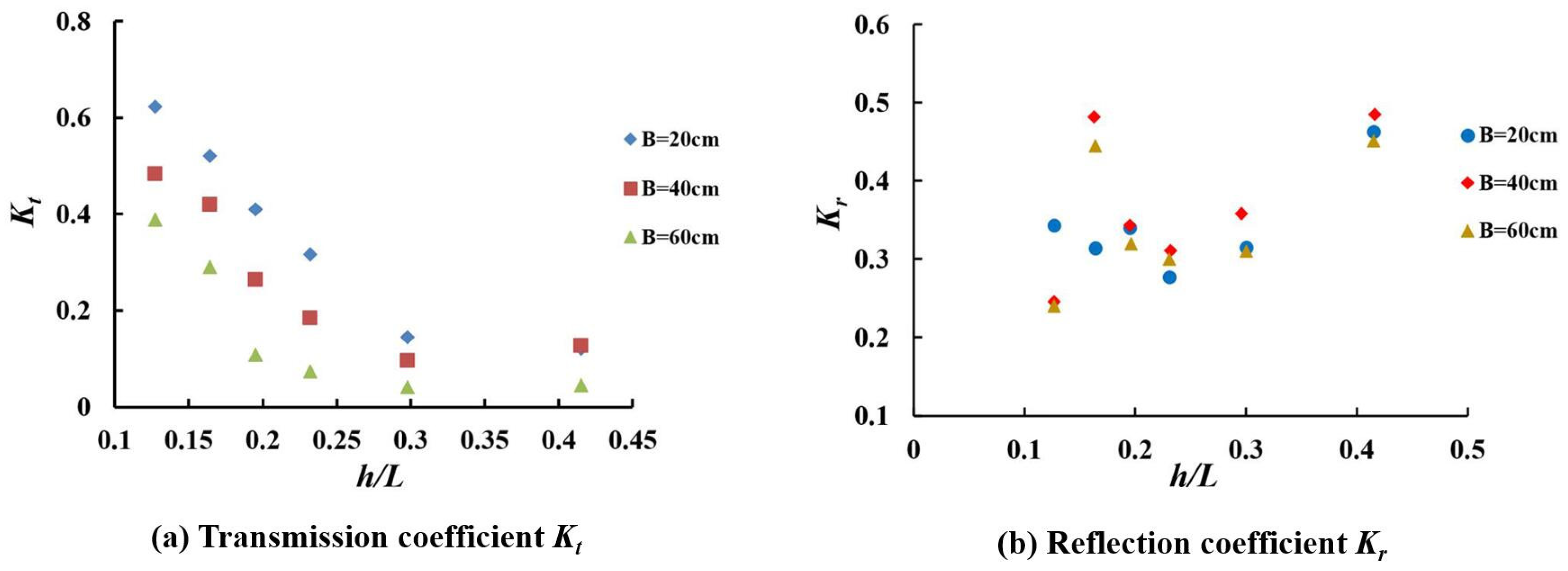
Figure 4 illustrates the relationship between the Kt and the Kr, as well as the B/L under a wave height of 4 cm, with top widths of 20 cm, 40 cm, and 60 cm. In Figure 4a, Kt decreases sharply as B/L. When B/L exceeds 0.3, the decrease of Kt becomes more gradual, approaching 0.1, indicating a significant effect on wave dissipation. For a given structural width, short-period waves experience friction and collisions with the front slope of the breakwater, making them prone to breaking as they ascend. As waves pass through the permeable pipes, they encounter wall friction, which intensifies the oscillations and interactions of water particles, leading to enhanced nonlinear wave motion, turbulence, and the formation of local vortices. This results in substantial wave energy dissipation and a considerable reduction in wave height behind the breakwater. In contrast, long-period waves retain a strong propagation ability and do not break when entering the permeable pipes; their primary energy loss comes from the friction of the pipe walls, resulting in a weaker reduction effect on the waves.
The behaviors of Kr and B/L differ, as shown in Figure 4b. Initially, the reflection coefficient Kr of the breakwater decreases as the B/L ratio increases. After reaching a minimum value, Kr increases with further increases in B/L.

3.2. Effect of Breakwater Slope

3.2.1. Same Slope in Front and Behind of the Breakwater

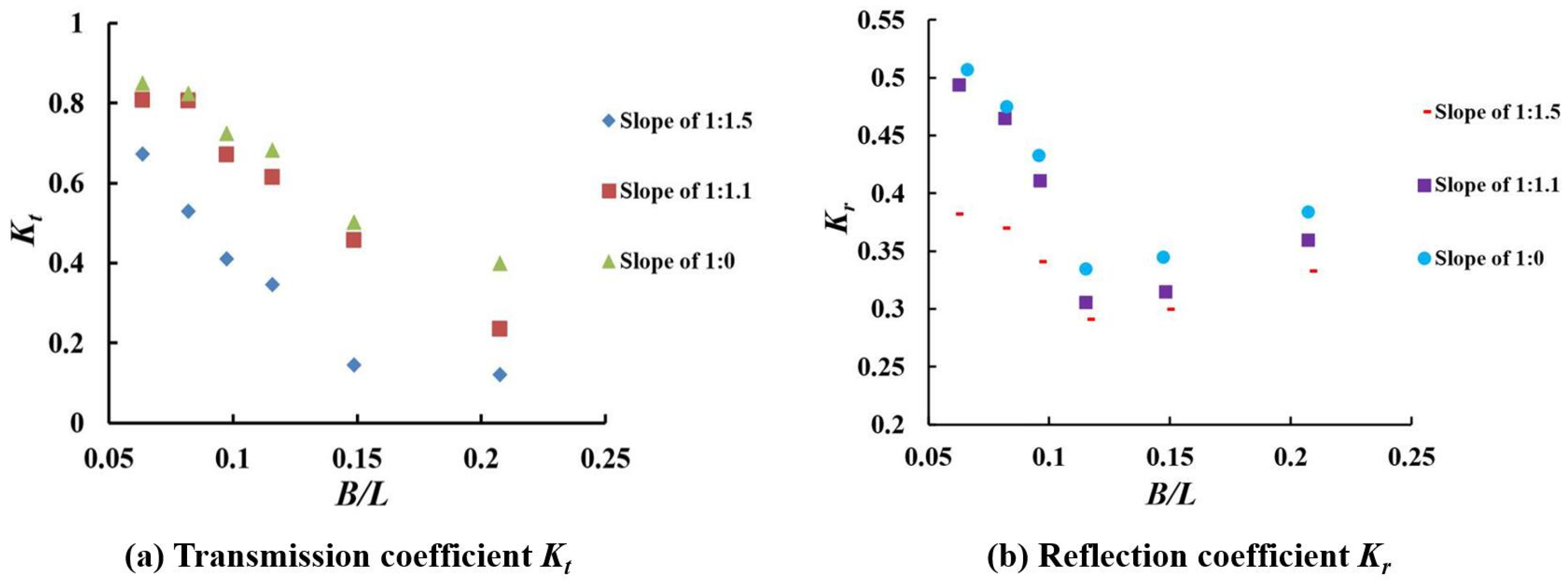
Figure 5a shows the relationship between Kt and B/L for a wave height of 8 cm and a structural top width of 20 cm, with breakwater slopes of 1:1.5, 1:1.1, and 1:0, respectively (see Figure 6). The data in Figure 5a indicate that Kt exhibits a good correlation with the slope of the breakwater, increasing as the slope becomes steeper and decreasing as B/L increases. This means the transmission coefficient is smallest for a slope of 1:1.5 and largest for a vertical breakwater with a slope of 1:0. The greater friction, collisions, and wave breaking against the sloping structure lead to more energy dissipation than in a vertical breakwater, resulting in a significant reduction in wave height behind the structure and lower Kt.
The variation of Kr and B/L for different slopes under the same conditions as Figure 5a is shown in Figure 5b. The comparison of Figure 5a,b reveals that Kr has a similar trend as Kt. The breakwater with a slope of 1:1.5 has the lowest reflection coefficient, while the one with a slope of 1:0 has the highest reflection coefficient.

3.2.2. Different Slopes in Front and Behind of the Breakwater

To assess the effect of perforated pipe structures on berth conditions in the harbor basin, tests were conducted under identical conditions (B = 20 cm, H = 8 cm). A slope ratio of 1:1.5, which showed superior wave reduction effects, was selected for the wave-facing surface in front of the breakwater. For the harbor basin behind the breakwater, slopes of 1:1.5, 1:1.1, and 1:0 were used (Figure 7). Figure 8 shows the variation of Kt and Kr for the different slope combinations. In Figure 8a, the change patterns for the three slopes are similar, with all values of Kt showing a slight increase as the slope becomes steeper, ranging from 0.1 to 0.74. For a given B/L, there exists minimal disparity in Kt values among the three slopes. For slopes behind the breakwater at ratios of 1:1.1 and 1:0, respectively, the transmission coefficient ranges from 0.2 to 0.7 and from 0.2 to 0.74, respectively. These values are lower compared to the conditions with the same slope in front and behind the breakwater, as depicted in Figure 5. This suggests that most wave energy dissipation occurs on the frontal slope of the breakwater, while the sloping or vertical structures behind the breakwater have a minimal impact on the transmission coefficient. For all three slope conditions, when B/L exceeds 0.2, Kt decreases to a range of 0.1–0.3, indicating enhanced wave energy dissipation.
In Figure 8b, the reflection coefficients Kr of the three types of breakwaters with different slopes behind them exhibit a similar variation pattern with an increase in the relative width B/L when the wave height is 8 cm. It initially decreases, reaching a minimum value at a relative width of about 0.15, and then increases. This minimum reflection coefficient indicates optimal reflection performance under these conditions. The range of reflection coefficients is mainly between 0.2 and 0.4, with the breakwater having a slope ratio of 1:1.5 behind it showing slightly higher values than the other two configurations.
A comparison of Figure 5b and Figure 8b indicates that while the same slope is maintained on the front side, varying the slope on the lee side significantly affects the reflection coefficient of the structure. Although the general trend remains consistent, the ranking of the three slopes changes, influenced by the variations in the embankment top width used during testing.

3.3. Different Structural Types

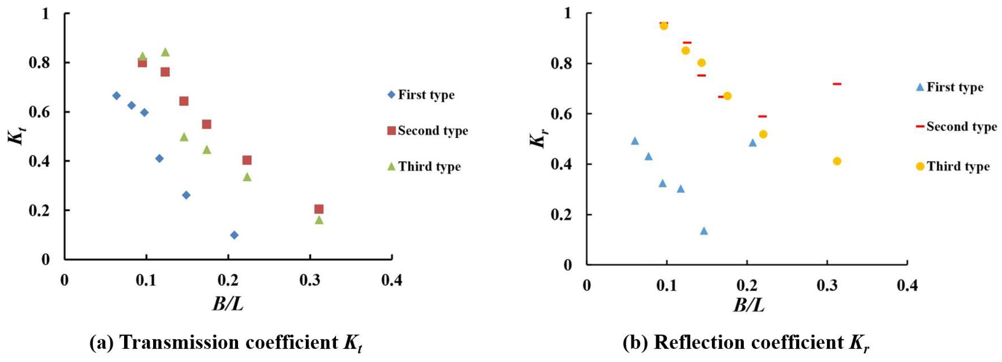
Figure 9a shows the relationship between Kt and B/L for various upper pipe diameters, with both the front and rear slopes of the breakwater set at 1:1.5. Figure 9a shows that Kt decreases as B/L increases for all three breakwater types. When B/L exceeds 0.3, Kt decreases to around 0.2 for all tested. types, indicating that a combined pipe diameter structure has strong wave damping capabilities.
Figure 9b presents the change in the reflection coefficient (Kr) and the relative width (B/L) for different breakwater types at a wave height of 4 cm. Both the first and second types of breakwaters exhibit a consistent trend in Kr with respect to B/L, namely initially decreasing and then increasing as B/L increases. The first type of breakwater has the lowest reflection coefficient, suggesting reduced wave pressure on its surface and greater structural stability. Compared to the second type, the first type achieves its minimum reflection coefficient at a smaller relative width. This implies that under constant wavelength conditions, the first type requires a narrower width. In practical engineering, using the first type of structure not only provides effective reflection performance but also reduces material requirements, offering economic benefits.

3.4. Wave Steepness (H/L)

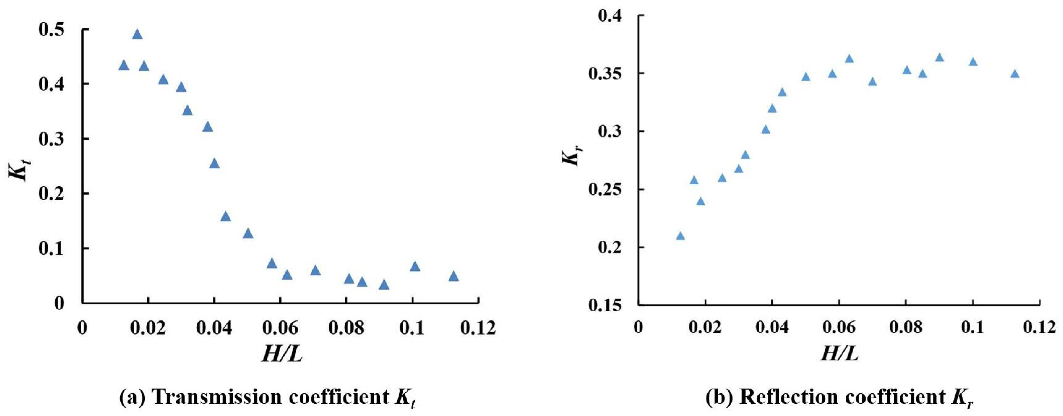
Figure 10 illustrates the variation of Kt and Kr with wave steepness H/L (where H represents wave height and L denotes wavelength) for a breakwater with a top width of the breakwater B = 60 cm and front and rear slopes of 1:1.5. It is seen that Kt sharply decreases with increasing wave steepness and reaches a minimum value of 0.1 when it exceeds 0.06. This indicates a significant wave reduction effect achieved by the permeable pipe breakwater.
The variation of Kr with H/L under the same conditions is shown in Figure 10b. Unlike the trend observed for the transmission coefficient. It is seen that the reflection coefficient of the breakwater sharply increases with the increase in wave steepness, peaking at around H/L = 0.06. For H/L > 0.06, Kr varies slightly with wave steepness. The results suggest that wave steepness is a key factor influencing the reflection coefficient of breakwaters. In practical applications, choosing an appropriate breakwater size based on wave conditions is crucial for effective wave reduction.

3.5. Relative Water Depths (h/L)

Figure 11a shows the variation in the transmission coefficient Kt with the relative water depth (h/L, where h is the water depth) for different breakwater top widths under test conditions of wave height H = 8 cm and slope ratio 1:1.5. The figure in Figure 11 indicates that Kt decreases significantly as h/L increases, reaching stability when h/L exceeds 0.3, which reflects a substantial wave reduction. Additionally, for a given water depth, Kt is inversely proportional to the top width of the breakwaters’ (B).
The relationship between Kr and h/L for various breakwater top widths is more complex, as shown in Figure 11b. It is seen that the Kr values for the three breakwater types fall within the range of 0.2 to 0.6. For breakwaters with a larger top B = 40 cm and B = 60 cm, Kr increases then decreases with increasing h/L. When Kr reaches a minimum at h/L = 0.22 and rises again in h/L. Conversely, for B = 20 cm, Kr decreases and then increases with the increase in h/L, possibly due to the differences between the top width B and wavelength L. In summary, the comparative analysis indicates that breakwaters with a top width of 60 cm possess smaller Kr and yield better reflective performance.

3.6. Comparison of Perforated Pipe and Double Horizontal Plate Breakwater

The transmission coefficients of the perforated pipe and double horizontal plate breakwaters under varying slopes and B/L ratios are presented in Figure 12a. The Kt decreases as B/L increases but rises with increasing slope. For slopes of 1:1.5, 1:1.1, and 1:0, respectively, Kt ranges between 0.1 and 0.48, 0.1 and 0.76, and 0.2 and 0.87 for the perforated pipe structure. The Kt of the double horizontal plate structure at a slope of 1:0 varies from 0.36 to 1.0. Under the same testing conditions, the perforated pipe structure shows superior wave-damping performance compared to the double horizontal plate structure. However, both breakwater types exhibit less effective performance for long-period waves.
Figure 12b illustrates the relationship between Kr and B/L for different breakwater types, considering a wave height of 8 cm. It can be observed that the Kr of the two types of permeable tube breakwaters with slopes of 1:1.1 and 1:0 is similar, while the Kr for all breakwater types initially increases, then decreases, and increases again as B/L rises. The difference between the maximum and minimum values is about 0.25. When the relative width is less than 0.3, the breakwater with a slope of 1:1.5 shows a significantly lower reflection coefficient than the other three structures. However, when the relative width exceeds 0.3, the reflection coefficients become comparable across all structures.
The reflection coefficient of the permeable horizontal plate is slightly higher than that of the permeable tube breakwater under identical conditions. This is partly due to the porous cross section of the permeable pipe structure, which suppresses most waves through vibration, allowing only a portion of the wave energy to be reflected by the impermeable pipe walls. In contrast, horizontal plates reflect waves mainly at specific vertical sections along the embankment, leading to a concentrated reflection effect that significantly affects both incident wave behavior and the generation of reflected waves.

4. Conclusions

In this study, the transmission coefficient (Kt) and reflection coefficient (Kr) of a perforated pipe breakwater were determined through laboratory experiments under various conditions, including top width, slope, pipe diameter, wave steepness, and relative water depth. The main conclusions of this study are as follows:
(1) The transmission coefficient Kt exhibits a decreasing trend with increasing B/L, wave steepness, and relative water depth. When B/L = 0.4, Kt decreases to approximately 0.1. For wave steepness above 0.06 or relative water depth exceeding 0.3, Kt tends to stabilize, indicating favorable wave attenuation under these conditions.
(2) An increase in the breakwater slope leads to a rise in Kt, with the smallest Kt and optimal wave dissipation achieved at a slope of 1:1.5. When the front slope is fixed at 1:1.5 and the rear slope varies, there is minimal change in Kt, suggesting that the primary wave energy loss occurs on the front slope of the breakwater.
(3) The reflection coefficient Kr initially decreases as B/L increases, reaching its minimum value at a B/L ratio of approximately 0.3. However, for B/L values greater than 0.3, the Kr starts to increase. The coefficient Kr of a slope with a ratio of 1:1.5 is minimized when the wave height is small. As the wave height increases, Kr values for slopes with ratios of 1:1.5, 1:1.1, and 1:0 increase. As wave steepness increases, the Kr exhibits a decreasing trend, then an increasing trend. The breakwater with a slope of 1:1.5 exhibits the lowest transmission and reflection coefficients, indicating superior wave energy dissipation.
(4) The combined pipe diameters (first type) have the lowest transmission and reflection coefficients among the three structures tested. A gradual increase in pipe diameter from top to bottom enhances the wave-absorbing capability of the breakwater by increasing surface wave friction and breaking, while also mitigating underwater waves and facilitating water exchange.
(5) The wave dissipation performance of the perforated pipe breakwater is superior to that of the double horizontal plate structure under identical conditions, with both structures demonstrating higher wave energy dissipation efficiencies for short-period waves.
(6) This study has limitations due to the model test size. Further investigation is needed to assess the impact of irregular waves, long-period waves, pipe wall thickness, and other factors on the wave absorption performance of permeable tube breakwaters. Additionally, research is necessary to examine the forces acting on and the stability of tube breakwaters under different conditions. A three-dimensional numerical model could be developed using numerical software to study the flow and pressure fields surrounding the breakwater in greater detail.

Author Contributions

Data curation, L.Y. and J.N.; funding acquisition, S.Y.; investigation, S.Y. and J.N.; supervision, Y.G.; writing—original draft, S.Y.; writing—review and editing, L.Y., B.S. and Y.G. All authors have read and agreed to the published version of the manuscript.

Funding

This research was funded by the Open Funds for Hubei Key Laboratory of Marine Geological Resources, China University of Geosciences, No. MGR202405, and the Natural Science Foundation of Shandong Province, No. ZR2022QE200.

Data Availability Statement

Data are contained within the article.

Conflicts of Interest

Author Lipeng Yang was employed by the company Qingdao Municipal Transport Development Centre. Author Jing Na was employed by the company Dalian Haiyang Fishery Engineering Planning, Design and Research Co., Ltd. The remaining authors declare that the research was conducted in the absence of any commercial or financial relationships that could be construed as a potential conflict of interest.

References

  1. Huang, Z.; Li, Y.; Liu, Y. Hydraulic performance and wave loadings of perforated/slotted coastal structures: A review. Ocean Eng. 2011, 38, 1031–1053. [Google Scholar] [CrossRef]
  2. Reeve, D.; Chadwick, A.; Fleming, C. Coastal engineering: Processes Theory and Design Practice; Spon Press: New York, NY, USA, 2012. [Google Scholar]
  3. Isaacson, M.; Baldwin, J.; Allyn, N.; Cowdell, S. Wave interactions with perforated breakwater. J. Waterw. Port Coast. Ocean. Eng. 2000, 126, 229–235. [Google Scholar] [CrossRef]
  4. Weigel, R. Closely spaced piles as a breakwater. Dock Harbour Auth. 1961, 41, 150–165. [Google Scholar]
  5. Cмирнoв, Г.H. Port and Port Buildings; China Communications Press: Beijing, China, 1984. [Google Scholar]
  6. Hou, G.B. Experimental study on pipe permeable breakwater. Coastal Eng. 1982, 1, 1–8. (In Chinese) [Google Scholar]
  7. Li, C.Z.; Cai, Y.; Wei, S.L. Computation of reflection coefficient for hollow-pipe porous breakwater. Ocean Eng. 1991, 4, 69–79. (In Chinese) [Google Scholar]
  8. Wen, S.C. Wave Principle; Shandong People’s Publishing House Press: Jinan, China, 1962; pp. 382–393. [Google Scholar]
  9. Ministry of Transport of the People’s Republic of China. Code for Sea Port Hydrology; China Communication Press: Beijing, China, 1999; pp. 35–50. [Google Scholar]
  10. Qiu, D.H.; Wang, X.G. Theoretical analysis of deep water thin plate breakwater. Port Waterw. Eng. 1986, 4, 8–12. (In Chinese) [Google Scholar] [CrossRef]
  11. Ju, L.H.; Yang, Z.J. Experimental research on coefficient of wave transmission through single immersed vertical barrier of open-type breakwater. Port Waterw. Eng. 2008, 4, 19–22. (In Chinese) [Google Scholar]
  12. Zhu, D.T. Hydrodynamic characteristics of vertical monolayer baffle permeable dike. Marine Engineering. Branch of China Oceanic Society. In Proceedings of the 18th China Offshore Engineering Symposium (II), Beijing, China, 28–31 December 2017; pp. 894–900. [Google Scholar]
  13. Yin, F.A. Study on Wave Permeability Characteristics of Baffle-Type Permeable Breakwater. Master’s Thesis, Hohai University, Nanjing, China, 2005; pp. 18–35. [Google Scholar]
  14. Fan, J.; Wang, Y.A.; Yang, S.H.; Yan, S.C.; Wang, W.; Qian, X.S. Experimental research on reflection coefficient and transmitted coefficient of double barriers penetrated breakwater. Ocean Eng. 2011, 29, 60–67. (In Chinese) [Google Scholar]
  15. Shao, J.; Chen, G.P.; Yan, S.C.; Yang, Q. An experimental study of the wave-permeating coefficient of vertical baffle permeable breakwater under irregular waves. Ocean Eng. 2016, 34, 50–57. (In Chinese) [Google Scholar]
  16. Syamsuri, A.M.; Suriamihardja, D.A.; Thaha, M.A.; Rachman, T. Effect of pipe wall roughness on porous breakwater structure on wave deformation. J. Eng. Trends Technol. 2021, 69, 147–151. [Google Scholar]
  17. Wang, Y.K. Experimental Study on Wave Attenuation of Different Open-Hole Porous Breakwaters. Master’s Thesis, Ludong University, Yantai, China, 2019. [Google Scholar]
  18. Neelamni, S.; Gayathri, T. Wave interaction with twin plate wave barrier. Ocean Eng. 2006, 33, 495–516. [Google Scholar] [CrossRef]
  19. Neelamni, S.; Rajendran, R. Wave interaction with T-type breakwaters. Ocean Eng. 2002, 29, 151–175. [Google Scholar] [CrossRef]
  20. Neelamni, S.; Rajendran, R. Wave interaction with ‘┴’-type breakwaters. Coastal Eng. 2002, 29, 561–589. [Google Scholar]
  21. Tao, J.W.; Wu, J.P.; Zheng, X.W. Experimental study on wave attenuation performance of +-type breakwater. J. Wuhan Univer. Technol. (Transp. Sci. Eng.) 2018, 42, 349–352. [Google Scholar]
  22. Wang, G.Y. Investigation on the Structure Type and Performance of the Special Breakwater. Master’s Thesis, Dalian University of Technology, Dalian, China, 2005. [Google Scholar]
  23. Yan, Y.X.; Zheng, J.H.; Zeng, X.C.; Xie, H.D. Experimental research on wave dissipation characteristics of multi-layer baffle piled permeable breakwater. Ocean Eng. 1998, 16, 68–75. (In Chinese) [Google Scholar]
  24. Wang, Q.; Liu, R.; Liang, B.C. Experimental study on wave-dissipating performance of pile-supported breakwater with perforated inclined wave screen. Coastal Eng. 2022, 41, 95–104. (In Chinese) [Google Scholar]
  25. Teh, H.M.; Venugopal, V. Performance evaluation of a semicircular breakwater with truncated wave screens. Ocean Eng. 2013, 70, 160–176. [Google Scholar] [CrossRef]
  26. He, F.; Huang, Z. Hydrodynamic performance of pile-supported OWC-type structures as breakwaters: An experimental study. Ocean Eng. 2014, 88, 618–626. [Google Scholar] [CrossRef]
  27. He, F.; Zhang, H.S.; Zhao, J.J.; Zheng, S.M.; Iglesias, G. Hydrodynamic performance of a pile-supported OWC breakwater: An analytical study. Appl. Ocean. Res. 2019, 88, 326–340. [Google Scholar] [CrossRef]
  28. Yu, D.J.; Feng, W.B.; Li, Y.B.; Yang, B. Experimental study and calculation of horizontal wave pressure of piled baffle penetrated breakwater. Port Waterw. Eng. 2015, 1, 19–24. (In Chinese) [Google Scholar]
  29. Lv, X.; Cheng, Y.Z.; Hu, Y.C.; Hang, X.Y. Experimental study on wave force characteristics of the porous I-type plate composition breakwater. Ocean Eng. 2020, 38, 49–55. (In Chinese) [Google Scholar]
  30. He, F.; Chen, Y.; Pan, J.P. Experimental study on hydrodynamic performance of labyrinth-type permeable breakwater. Ocean Eng. 2024, 5, 1–12. (In Chinese) [Google Scholar]
  31. Yu, D.Y.; Gao, Z.Y.; Dou, Z.H.; Qu, M.; Ge, X.L. Experimental study on the wave dissipation performance of a permeable breakwater structure with reverse-arc inclined plate. Coastal Eng. 2023, 42, 111–120. (In Chinese) [Google Scholar]
  32. Pan, C.C. Experimental Investigation on the Hydrodynamic Characteristics of Arc-Plate Type Breakwater. Master’s Thesis, Dalian University of Technology, Dalian, China, 2014. [Google Scholar]
  33. Zhao, L.P.; Zhu, Y.Z.; Xie, A.Y.; Zhou, J.F. Experimental study on wave forces on curved breakwater. Ocean Eng. 2015, 33, 35–41. [Google Scholar]
  34. Wang, L.X. Study on Random Wave Action on Twin-Arc-Plate Permeable Breakwater. Master’s Thesis, Ludong University, Yantai, China, 2021. [Google Scholar]
  35. Yagci, O.; Kirca VS, O.; Kabdasli, M.S.; Celik, A.O.; Unal, N.E.; Aydingakko, A. An experimental model application of wave screen: Dynamic pressure, water particle velocity, and wave measurements. Ocean Eng. 2006, 33, 1299–1321. [Google Scholar] [CrossRef]
  36. Rao, S.; Shirlal, K.G.; Varghese, R.V.; Govindaraja, K.R. Physical model studies on wave transmission of a submerged inclined plate breakwater. Ocean Eng. 2009, 36, 1199–1207. [Google Scholar] [CrossRef]
  37. Wang, G.Y.; Zhao, W.J.; Xiang, Z.Q.; Zhu, G.C. Experimental study on wave damping performance of porous inclined plate. Adv. Sci. Technol. Water Resour. 2017, 37, 22–26. [Google Scholar]
  38. Fan, Y.P.; Li, J.X.; Liu, S.X.; Liu, Y.; Sui, J.K. Study on wave dissipation performance of permeable breakwater of double porous inclined baffle. Port Waterw. Eng. 2020, 7, 7–12. (In Chinese) [Google Scholar]
  39. Tang, W.; Hu, J.; Chen, Y.Z.; Hu, Y.C. Analysis of structure and wave dissipation characteristics of a new type of perforated composite plate breakwater. Hydro-Sci. Eng. 2017, 5, 37–44. [Google Scholar]
  40. Guo, Y.C.; Mohapatra, S.C.; Guedes, S.C. Experimental performance of multi-layered membrane breakwaters. Ocean Eng. 2023, 281, 114716. [Google Scholar] [CrossRef]
  41. Guo, Y.C.; Mohapatra, S.C.; Guedes, S.C. An experimental study on the performance of combined membrane breakwaters against incident waves. Ocean Eng. 2023, 280, 114793. [Google Scholar] [CrossRef]
  42. Zhu, Y.L.; Li, Y.; Chen, D.C.; Tao, A.F. Numerical study on wave attenuation properties of piled baffle penetrated breakwater. Ocean Eng. 2015, 33, 53–62. (In Chinese) [Google Scholar]
  43. Yu, T.S.; Tang, J.H.; Meng, X.Y. Analysis of the hydrodynamic characteristics of an anti-deposition permeable breakwater. J. Harbin Eng. Univ. 2023, 44, 1295–1303. [Google Scholar]
  44. Yu, T.S.; Zhao, X.W.; Tang, J.H.; Zhang, Z.Y.; Chen, X.Y. Experimental and prediction study on wave run-up of anti-deposited permeable breakwater. J. Tianjin Univ. (Sci. Technol.) 2023, 56, 831–839. [Google Scholar]
  45. Sundar, V.; Subbarao, B.V.V. Hydrodynamic performance characteristics of quadrant front-face pile-supported breakwater. J. Waterw. Port Coast. Ocean. Eng. 2003, 129, 22–33. [Google Scholar] [CrossRef]
  46. Du, P.L.; Sun, Z.C.; Liang, S.X. Numerical study on wave dissipation performance of new type vertical permeable breakwater. Ocean Eng. 2021, 39, 12–20. (In Chinese) [Google Scholar]
  47. Wu, Y.Y.; Li, X.Y.; Wang, Q.; Zhu, X.S.; Guo, W.J.; Dong, D.L.; Lu, D.W. Numerical study on the influence factors of the wave attenuation performance of an arc-plate type open breakwater. Ocean Eng. 2019, 37, 59–67. (In Chinese) [Google Scholar]
  48. Wang, X.L.; Chen, Y.K.; Liu, Y.; Wang, X.G. Numerical and experimental study on wave dissipation characteristics of a new-type floating breakwater with anti-arc surface. J. Waterw. Harb. 2021, 42, 567–581. [Google Scholar]
  49. Cho, I.H.; Kim, M.H. Wave absorbing system using inclined perforated plates. Fluid Mech. 2008, 608, 1–20. [Google Scholar] [CrossRef]
  50. Gayen, R.; Mondal, A. Water wave interaction with two symmetric inclined permeable plates. Ocean Eng. 2016, 124, 180–191. [Google Scholar] [CrossRef]
  51. Cheng, Y.Z.; Lin, Z.Y.; Hu, G.; Lv, X. Numerical Simulation of the Hydrodynamic Characteristics of the Porous I-type Composite Breakwater. J. Mar. Sci. Appl. 2022, 21, 140–150. [Google Scholar] [CrossRef]
  52. JTJ/T 234-2001; Wave Model Test Regulation. China Communication Press: Beijing, China, 2001.
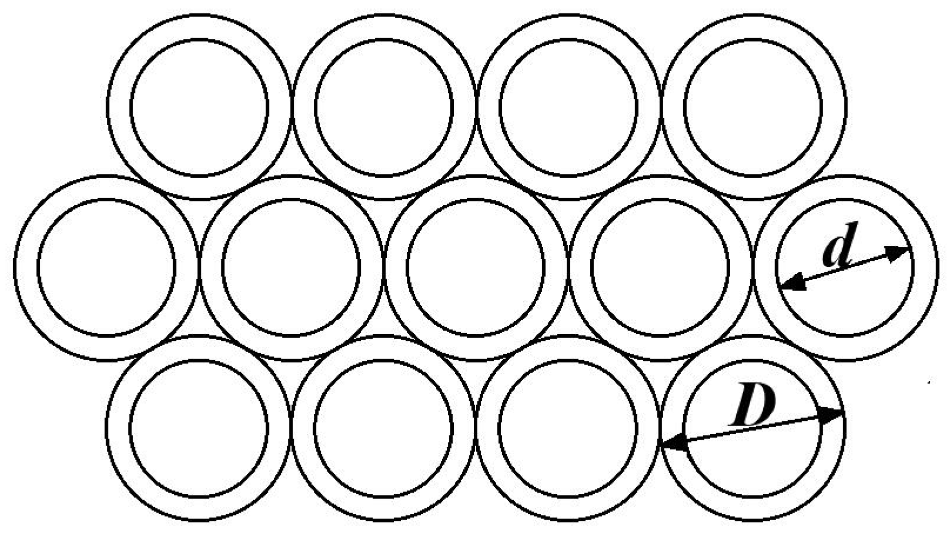
Figure 1. Sketch of Hou’s design for a permeable pipe breakwater.
Jmse 12 02137 g001
Figure 2. Sketch of experimental layout.
Jmse 12 02137 g002
Figure 3. Experimental model for testing breakwaters.
Jmse 12 02137 g003
Figure 4. Variation of Kt (a) and Kr (b) with different relative top widths of the breakwater (B/L).
Jmse 12 02137 g004
Figure 5. Variation of Kt (a) and Kr (b) with various relative top widths (B/L) and slopes.
Jmse 12 02137 g005
Figure 6. Sketch of breakwater with the same front and rear slope.
Jmse 12 02137 g006
Figure 7. Sketch of breakwater with different front and rear slopes.
Jmse 12 02137 g007
Figure 8. Variation of Kt and Kr with different B/L and slopes behind breakwater.
Jmse 12 02137 g008
Figure 9. Variation of Kt and Kr with the relative top width of the breakwater for different pipe diameters (H = 4 cm).
Jmse 12 02137 g009
Figure 10. Variation of Kt and Kr with different wave steepness (H/L).
Jmse 12 02137 g010
Figure 11. Variation of Kt and Kr with different relative water depths (h/L).
Jmse 12 02137 g011
Figure 12. Variation of Kt and Kr with the relative structure width of different breakwater conditions (H = 8 cm, B = 40 cm).
Jmse 12 02137 g012
Table 1. Experimental parameters.
RunBreakwater TypesSlope in Front of the BreakwaterSlope Behind the BreakwaterTop Width of the Breakwater (cm)Wave Height (cm)Wave Period (s)
1First type of breakwater1:1.51:1.520, 40, 604, 80.79, 0.95, 1.11, 1.25, 1.42, 1.74
21:1.51:1.5606, 10, 12, 14
31:1.11:1.120, 408
41:01:020, 408
51:1.51:1.1208
61:1.51:0204, 8
7Second type of breakwater1:1.51:0304
8Third type of breakwater1:1.51:0304
9Double horizontal plate of breakwater1:01:0408
Disclaimer/Publisher’s Note: The statements, opinions and data contained in all publications are solely those of the individual author(s) and contributor(s) and not of MDPI and/or the editor(s). MDPI and/or the editor(s) disclaim responsibility for any injury to people or property resulting from any ideas, methods, instructions or products referred to in the content.