Article

Simulation Study on Detection and Localization of a Moving Target Under Reverberation in Deep Water

1
State Key Laboratory of Acoustics, Institute of Acoustics, Chinese Academy of Sciences, Beijing 100190, China
2
University of Chinese Academy of Sciences, Beijing 100049, China
*
Author to whom correspondence should be addressed.
J. Mar. Sci. Eng. 2024, 12(12), 2360; https://doi.org/10.3390/jmse12122360
Submission received: 14 November 2024 / Revised: 9 December 2024 / Accepted: 20 December 2024 / Published: 22 December 2024
(This article belongs to the Section Ocean Engineering)

Abstract

:
Deep-water reverberation caused by multiple reflections from the seafloor and sea surface can affect the performance of active sonars. To detect a moving target under reverberation conditions, a reverberation suppression method using multipath Doppler shift in deep water and wideband ambiguity function (WAF) is proposed. Firstly, the multipath Doppler factors in the deep-water direct zone are analyzed, and they are introduced into the target scattered sound field to obtain the echo of the moving target. The mesh method is used to simulate the deep-water reverberation waveform in time domain. Then, a simulation model for an active sonar based on the source and short vertical line array is established. Reverberation and target echo in the received signal can be separated in the Doppler shift domain of the WAF. The multipath Doppler shifts in the echo are used to estimate the multipath arrival angles, which can be used for target localization. The simulation model and the reverberation suppression detection method can provide theoretical support and a technical reference for the active detection of moving targets in deep water.

1. Introduction

Due to the presence of reverberation, the detection performance of active sonars can be significantly affected. Currently, methods for suppressing reverberation can be categorized into time-domain methods, spatial-domain methods, time–frequency analysis methods, and Doppler shift domain methods. Time-domain methods primarily apply matched filtering to the received signals of active sonars to enhance the output signal-to-noise ratio. For instance, Zhang M et al. introduced channel-matching techniques into active sonars, employing a sparsification processing algorithm based on least squares matching pursuit (LSMP) to estimate channel responses and detect echoes, thereby achieving the aggregation of multipath energy to suppress reverberation [1]. Spatial-domain methods mainly utilize adaptive beamforming to improve the resolution of the main lobe in the beam output [2,3]. The integration of time- and spatial-domain methods is also introduced into the field of sonar signal processing in areas such as space–time adaptive processing (STAP) [4,5]. Time–frequency analysis methods exploit the differences in the time–frequency characteristics of echoes and reverberation to separate and suppress reverberation in the time–frequency domain [6,7,8].
Doppler shift is the Doppler frequency of the center frequency. Doppler shift domain methods utilize the differences in Doppler shift characteristics between the moving target and the stationary reverberation interference. Aspects of the stationary reverberation interference, such as the interface reverberation, typically exhibit zero Doppler shift, whereas a moving target usually has a non-zero Doppler shift. This distinction allows for the separation and suppression of reverberation in the Doppler shift domain. In this process, Doppler-sensitive signals, such as binary phase-shift keying (BPSK) signals coded with an m-sequence (i.e., pseudorandom code phase-modulated signals, PCPM signals), are utilized [9]. Jourdain et al. investigated the superior delay and Doppler shift resolution of PCPM signals compared to common signals such as linear frequency-modulated (LFM) and hyperbolic frequency-modulated (HFM) signals [10]. It demonstrates the utility of measuring target ranges and Doppler shifts. Colin et al. explored the use of PCPM signals in low-frequency active sonar (LFAS) for shallow-water antisubmarine warfare (ASW), and the experimental results indicated their potential for enhancing classification performance in cluttered environments [11]. Yang et al. conducted active detection experiments in harbor environments using PCPM signals as transmitted signals, and they processed the received signals in the Doppler shift domain to suppress reverberation and employed multi-ping Doppler analysis to track moving targets [12].
Compared to their performance in shallow water, active sonars exhibit significant differences in the multipath arrival structure and background reverberation of received signals in deep water. In shallow water, multipath signals are often challenging to distinguish in time domains, while there is an obvious multipath arrival structure in deep water. Regarding background reverberation, the time-domain structures of shallow- and deep-water reverberations differ considerably. Shallow-water reverberation is characterized by a continuous attenuation process in the time domain [13]. In deep water, the initial reverberation caused by a single seabed scattering event also follows a continuous attenuation process. However, since the sound waves are reflected multiple times between the seabed and the sea surface and the propagation times of them reflecting between the interfaces are much longer than those in shallow water, periodic reverberation will be generated. This reverberation with multiple peaks manifests a “jagged” pattern in its amplitude variation over time [14]. This complexity increases the difficulty of distinguishing target echoes from reverberation in the time domain in deep water.
Regarding the multipath Doppler effects of moving target echoes, the Doppler factors of each propagation path are not identical. Existing research on multipath Doppler factors primarily focuses on shallow-water environments. Huang S et al. established a multipath signal model in a homogeneous sound speed layer in shallow water using the image-source method [15]. They derived the multipath Doppler factors based on geometric relationships, showing that these factors are related not only to the target’s speed but also to the waveguide environment. Given the obvious multipath structure in deep water, the differences in multipath Doppler factors can effectively aid in distinguishing multipath signals and suppressing reverberation in the Doppler shift domain. Considering the differences in active sonar applications between deep and shallow water, it is of significant importance to study the active sonar’s received signal systems and detection methods in deep water.
In deep water, reverberation generated by interactions between the sea surface and seabed is typically the primary interference for active sonars, surpassing the impact of ambient noise [14]. This study focuses on active sonars operating under such conditions, where reverberation dominates as the main background interference. Aiming at the detection and localization of a moving target under reverberation in the deep-water direct sound zone, this paper is organized as follows. The active sonar simulation model based on the emitting source and the vertical short array is established in Section 2, including the model of moving target echoes and time-domain reverberation. A method for detection and localization of a moving target using deep-water multipath Doppler shift and WAF is proposed in Section 3, followed by algorithm procedures and simulation analysis. The localization performance of this method is analyzed in Section 4. The conclusions are given in Section 5.

2. Models for Active Sonars’ Received Signals in Deep Water

2.1. Scattered Sound Field of Targets

In an acoustic field, the total sound field satisfies the Helmholtz integral equation as follows [16]:
S [ ϕ ( r 0 , r S ) G ( r , r S ) n G ( r , r S ) ϕ ( r 0 , r S ) n ] d S = { 4 π ϕ s ( r 0 , r ) , r   is   outside   the   surface   S 4 π ϕ i ( r 0 , r ) , r   is   inside   the   surface   S ,
where the source is a point source located at r 0 . r S is an integration point on the surface S of the scatterer. n is the outer normal vector of the surface S . The Green’s function G ( r , r ) represents the acoustic field generated by a point source δ ( r r ) concentrated at r = r . The total sound field satisfies ϕ ( r ) = ϕ s ( r ) + ϕ i ( r ) , and ϕ s ( r ) and ϕ i ( r ) are the potential functions of the scattered and incident sound fields, respectively.
Under the Kirchhoff approximation, the incident and scattered sound fields on the illuminated surface of a rigid scatterer satisfy the following conditions:
{ ϕ s = ϕ i ( ϕ s + ϕ i ) n = 0 .
In the scattering calculation with the ray theory in [17], the sound field is represented using the image-source method, and the matrix expression of the scattered sound field is not provided, which is convenient for simulation. This paper is different from [17]. It uses the expression of the scattered sound field defined in Equation (1) and Kirchhoff approximation to simplify the integral formula. And the matrix expression of the scattered sound field is obtained through the following derivation with ray-tracing techniques [18].
For Equation (1), if only the scattered sound field outside the surface S is considered, we have:
ϕ s ( r ) = 1 2 π S ϕ i ( r S ) G ( r , r S ) n d S .
According to ray theory, in a homogeneous waveguide, the incident potential function can be described using the image-source method. Reflected rays from the sea surface and seabed are considered as rays emitted by image sources, and the target is also equivalent to a source. Thus, the scattering problem is transformed into a multi-source propagation problem. However, in the case of an arbitrary sound speed profile, ray-tracing techniques must be applied to calculate the actual rays. Since a limited number of high-energy eigenrays is sufficient to capture the primary characteristics of the acoustic field, it is unnecessary to consider additional eigenrays with more complex propagation paths and significantly attenuated energy. The incident potential function is then expressed as a superposition of eigenrays between the source and the field points as follows [19]:
ϕ i ( r S ) = m = 1 M A m R m e i k R m ,
where k is the wave number; A m is the attenuation coefficient for the m-th eigenray during propagation, excluding the effect of distance; R m represents the distance from the source to the incident point for the m-th eigenray; and M denotes the number of eigenrays.
In the case of backscattering, the Green’s function can also be expressed in the form of the incident potential function [19]:
G ( r , r S ) = n = 1 N B n r n e i k r n .
where B n is the attenuation coefficient for the n-th eigenray during propagation, excluding the effect of distance; r n represents the distance from the exit point to the target for the n-th eigenray; and N denotes the number of eigenrays. Substituting Equations (4) and (5) into Equation (3) yields the scattered sound field of targets in deep water for the case of multi-static active sonars:
ϕ S ( r ) m = 1 M n = 1 N A m B n R ¯ m r ¯ n e i k ( R ¯ m + r ¯ n ) ( i k 2 π S e i k ( Δ R m + Δ r n ) ( cos θ m + cos ϑ n ) d S ) ,
where R ¯ m and r ¯ n represent the equivalent distances of the m-th incident eigenray from the source to the geometric reference point of the target and the n-th outgoing eigenray from the same point to the receiver location, respectively. Δ R m and Δ r n denote the distances from the incident point of the m-th incident ray and the exit point of the n-th outgoing ray on the target surface to the geometric reference point of the target, respectively. θ and ϑ represent the incident and scattering angles, respectively. We can define
S ( θ | ϑ | ω ) = i k 2 π S e i k ( Δ R + Δ r ) ( cos θ + cos ϑ ) d S
as the scattering function of the plane waves in free space under the Kirchhoff approximation, where ω is the angular frequency, which is the product of the wave number and the sound speed. Then, the scattered sound field ϕ S m n at the receiving point generated by the m-th incident ray and the n-th outgoing ray can be expressed as:
ϕ S m n ( ω ) ϕ i ( R ¯ m ) S ( θ m | ϑ n | ω ) G ( r ¯ n ) .
Taking the geometric reference point of the target as the zero-phase point of the incident sound wave, we have ϕ i ( R ¯ m ) = 1 . Thus,
S ( θ m | ϑ n | ω ) ϕ S m n ( ω ) / G ( r ¯ n ) .
After modeling the rigid target and obtaining the data of ϕ S m n ( ω ) through the boundary element method [20], the scattering function of the plane waves in free space can be derived according to Equation (9).
Finally, we obtain the matrix expression for the scattered sound field in the frequency domain of a stationary target in deep water, which is called the ray-Kirchhoff approximation method, given by:
ϕ s ( ω ) = m = 1 M n = 1 N ϕ S m n ( ω ) = f i T S G ,
where
f i = [ A 1 R ¯ 1 e i k R ¯ 1 , A 2 R ¯ 2 e i k R ¯ 2 , , A M R ¯ M e i k R ¯ M ] T ,
S = [ S ( θ 1 | ϑ 1 | ω ) S ( θ 1 | ϑ 2 | ω ) S ( θ 1 | ϑ N | ω ) S ( θ 2 | ϑ 1 | ω ) S ( θ 2 | ϑ 2 | ω ) S ( θ 2 | ϑ N | ω ) S ( θ M | ϑ 1 | ω ) S ( θ M | ϑ 2 | ω ) S ( θ M | ϑ N | ω ) ] ,
G = [ B 1 r ¯ 1 e i k r ¯ 1 , B 2 r ¯ 2 e i k r ¯ 2 , , B N r ¯ N e i k r ¯ N ] T ,
and “T” denotes the transpose of a matrix.

2.2. Echoes of Moving Targets

According to Section 2.1, if the transmitted signal is s ( t ) , the received signal in the time domain of a stationary target in deep water can be expressed as:
g ( t ) = m = 1 M n = 1 N s ( t ) ϕ S m n ( t ) = m = 1 M n = 1 N g m n ( t ) ,
where “ ” denotes the convolution operator and ϕ S m n ( t ) is the inverse Fourier transform of ϕ S m n ( ω ) .
For a moving target in the waveguide, the “Multi-Scale Multi-Lag” (MSML) model can be used to predict the echo [21]. This model assigns each individual propagation path its own Doppler factor and time delay. The echo under this model is given by:
p e c h o ( r s , r ; t ) = m = 1 M n = 1 N g m n ( α m n t ) ,
where α m n represents the Doppler factor for the m-th incident path and the n-th outgoing path. After calculating the scattered sound field of a stationary target and the multipath Doppler factors α m n , the echo of a moving target can be determined by Equation (15).
There are various incident and outgoing paths for the propagation of sound waves from the source to the target and then to the receiver in deep water. As shown in Figure 1a, the direct-surface reflection (DSR) propagation path for the waves is depicted. The wave travels directly from the source to the target, where it is scattered and then exits from the target, reaching the receiver via a single sea-surface reflection path. Taking the DSR path as an example, the theoretical value of the Doppler factor for this path can be analyzed when there is relative motion between the target and the sonar. Then, this theoretical value is simplified in relation to acoustic field parameters, the pulse width T of the transmitted signal, and the target velocity.
We assume that the source and receiver are collocated at depth H on the seabed, and the target moves horizontally with speed v at depth h. The initial horizontal distance between the sonar and the target is R. The Doppler factor is defined as the ratio of the received signal pulse width T’ to the transmitted signal pulse width T for active sonars [15]. Therefore, the Doppler factor for this path is given by:
α = T T = 1 + t 2 t 1 T ,
where t 1 and t 2 represent the propagation time of the front and back edge of the pulse along the incident–outgoing path, respectively. To study the Doppler factor for this path, it is necessary to analyze the propagation paths and times of the front and back edges of the transmitted signal. Figure 1a,b illustrate the transmission and reception models for the front and back edges of the transmitted pulse, respectively. Within the studied direct zone in deep water, rays can be approximated as lines, and thus, the rays are depicted as lines in the transmission and reception models.
In Figure 1a, the time for the front edge of the pulse to transmit from the source to the target is t 1 , and the time for the signal to be scattered by the target and received by the receiver is t 1 . Thus, the total time required for the front edge to complete the transmission and reception process is t 1 = t 1 + t 1 . Similarly, in Figure 1b, after a pulse width T, the horizontal distance between the target and the sonar becomes R + vT. The time for the back edge of the pulse to transmit from source to target is t 2 , and time for the signal to be scattered by the target and received by the receiver is t 2 . And the total time required for the back edge to complete the transmission and reception process is t 2 = t 2 + t 2 . One notes that, in practice, v t 1 , v t 2 R , t 1 can be expressed as the time delay along the incident–outgoing path when the horizontal distance between the target and the sonar is R, and t 2 is the time delay along the same path when the horizontal distance is R + vT. By using BELLHOP to calculate the difference between these two time delays [22], Δ t = t 2 t 1 , the theoretical value of the Doppler factor for this incident–outgoing path can then be obtained from Equation (16).
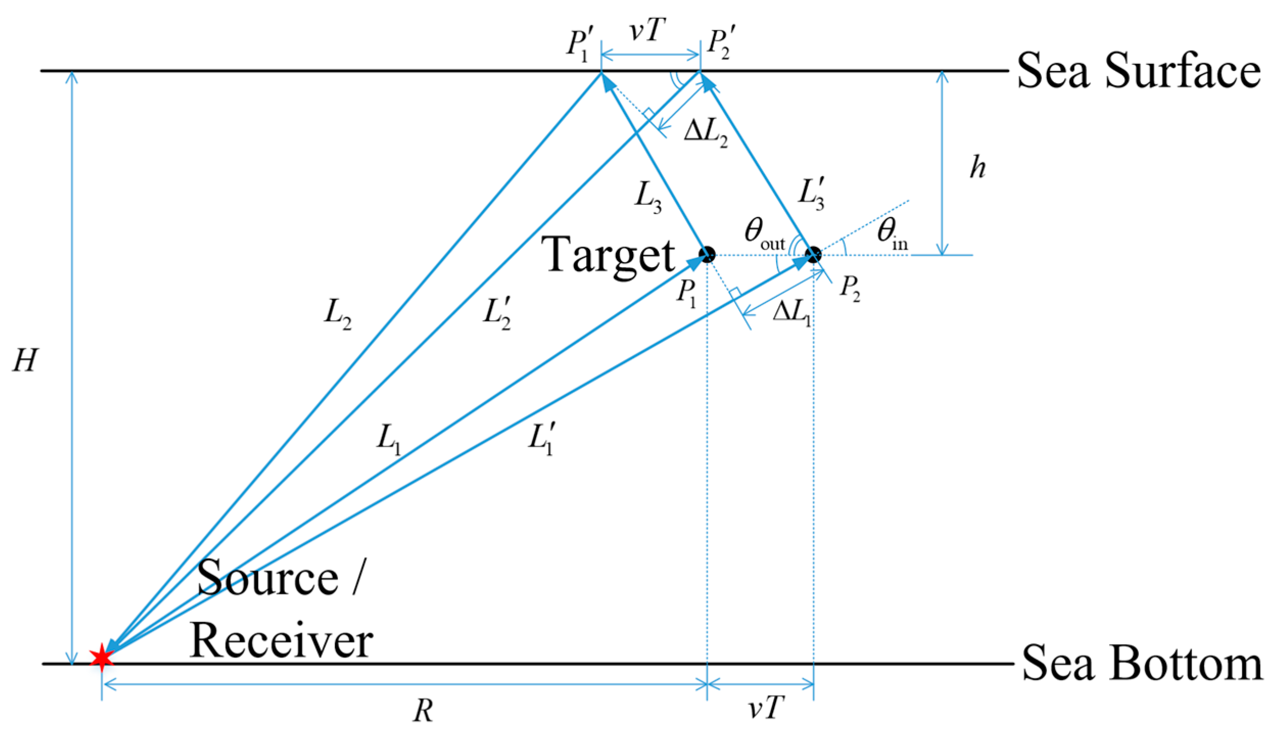
From the definition of the Doppler factor, it can be seen that the Doppler factor for a particular path is determined by the difference in the time required for the transmission and reception of the front and back edges of the transmitted pulse. The followings investigate how to simplify the calculation of the Doppler factor using the pulse width of the transmitted signal, the target velocity, and the acoustic field parameters. The simplified calculation is illustrated in Figure 2, where the rays are still approximated as lines. For ease of annotation, the target is simplified as a point in the schematic. The initial position of the target is P 1 , and after a pulse width T, the target moves to P 2 . The distances from the source to P 1 and P 2 via the direct path are L 1 and L 1 , respectively. After reaching the target via the direct path, the distances for the signal to travel from P 1 and P 2 and then return to the receiver via the sea-surface reflection path are L 2 + L 3 and L 2 + L 3 , respectively. It can be seen that the time difference Δ t for the transmission and reception of the front and back edges of the pulse can be reflected in the difference in distances.
From the schematic and geometric relationships, it can be derived that:
L 1 = R 2 + ( H h ) 2 , L 1 = ( R + v T ) 2 + ( H h ) 2 , L 2 + L 3 = R 2 + ( H + h ) 2 , L 2 + L 3 = ( R + v T ) 2 + ( H + h ) 2 .
Then, Δ t can be simplified by:
Δ t = L 1 L 1 c + L 2 + L 3 ( L 2 + L 3 ) c ,
where c represents the reference sound speed. Since v t R , we have L 3 L 3 , and Δ t can be further simplified as follows:
Δ t L 1 L 1 c + L 2 L 2 c .
Drawing perpendicular lines from P 1 and P 1 to the paths represented by L 1 and L 2 , respectively, under the assumption of long horizontal distance between the source and the target ( v t R ), the following equation holds true based on geometric relationships:
Δ t Δ L 1 + Δ L 2 c = v T cos θ in + v T cos θ out c ,
where θ in and θ out represent the receiving angle of the direct path in the incident process and the emitting angle of the sea surface reflection path in the outgoing process, respectively. Based on the derivation, once the sound field is set, the required emitting and receiving angles can be obtained using BELLHOP. Subsequently, the Doppler factors for different incident–outgoing paths can be simply calculated.
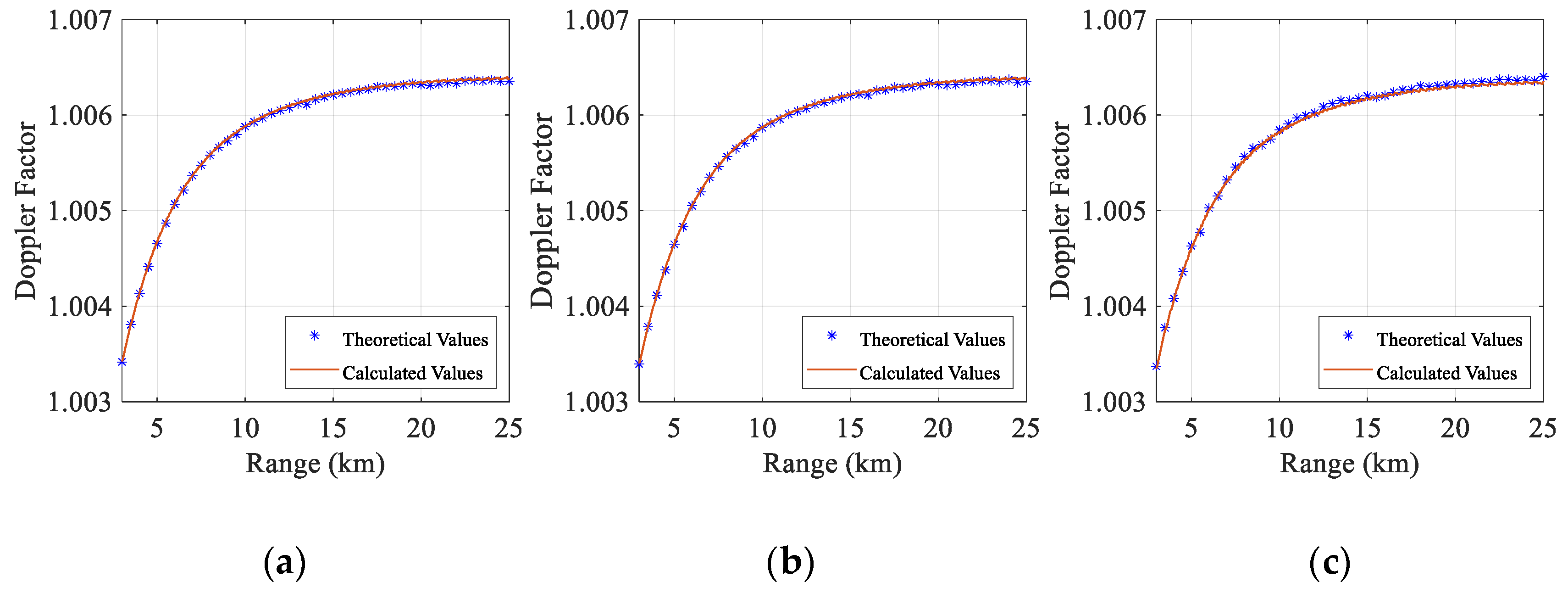
The above analysis provides theoretical values and calculated values of the Doppler factor for the DSR path as an example. Following the same derivation process, Doppler factors for other paths can similarly be obtained. Simulations are conducted to compare the theoretical and calculated values of multipath Doppler factors under different horizontal distances between the sonar and the target within the direct zone in deep water with the Munk sound speed profile [23]. These multipaths include several typical incident–outgoing paths, such as a direct–direct path (DD), a direct–surface reflection path (DSR), and a surface reflection–surface reflection path (SRSR). The theoretical values are derived from Equation (16) by calculating the differences in time delays, while the calculated values are obtained using the simplified method based on the arrival angles of the rays. The setup of the sound field is consistent with this in Figure 2, utilizing the Munk sound speed profile, with a sea depth of 5000 m, a target depth of 50 m, and a pulse width of 4.09 s of the signal, and both the source and receiver collocate at a depth of 4990 m on the seabed.
Setting the target speed to −5 m/s (where the negative sign indicates that the target moves away from the source), the theoretical and calculated values of Doppler factors for different paths are analyzed. These two values as a function of the horizontal distance between the sonar and the target are shown in Figure 3.
In Figure 3, it can be seen that, in deep water with the Munk sound speed profile, the calculated values of the Doppler factors exhibit a high degree of agreement with the theoretical values. This concordance is attributed to the fact that the studied distance falls within the direct zone in deep water, where the propagation paths of rays can be approximated as lines, thus ensuring the validity of the angle approximations.
By combining the Doppler factors for different paths with the scattered sound field of the stationary target, the echoes of the moving target in deep water can be derived via Equation (15).

2.3. Time-Domain Waveforms of Reverberation

This paper employs a model based on the ray theory and a meshed grid division of scatterers to simulate the time-domain waveforms of seabed reverberation in deep water. This model can calculate both mono-static and multi-static reverberation and explain the generation of reverberation [14]. The model first divides the seabed into the regular grids and then uses ray theory to calculate the precise time at which each scattering element generates the reverberation in a rectangular grid. Subsequently, the time-domain waveform of reverberation is computed.
The schematic of the mesh method applied to seabed scatterers is illustrated in Figure 4. It can be seen that the seabed reverberation generated by a scattering element involves the following processes: (1) the propagation of incident waves transmitted by the source through the ocean; (2) the scattering process of incident waves at the scatter element; (3) the propagation of scattered waves through the ocean; and (4) the superposition of scattered waves received by the receiver to form the reverberation. In Figure 4, θ inc and θ scatt represent the grazing angles of the incident and outgoing rays, respectively. ψ is the angle between the projections of the incident and scattered rays in the x-y plane. For mono-static active sonar, ψ = 0 ° .
Unlike predicting time-domain waveforms of reverberation by dividing the seabed region into annular segments [24], after dividing the seabed into grids as shown in Figure 4, one can assume that the transfer functions of the incident ray from the source to different scatterers within a scattering element are the same, and that the transfer functions of the scattered ray from different scatterers within a scattering element to the receiver are also the same. Under these assumptions, the time-domain expression for the seabed reverberation generated by the d-th scattering element can be derived as follows: [25]
p rev , d ( t ) = q = 1 Q ( r ) i = 1 N j = 1 M p inc , i ( r i ) p scatt , j ( r j ) A r ( q ) S ( θ inc , i , θ scatt , j ) s ( t ) exp ( j φ ( q ) ) ,
where p inc , i and p scatt , j represent transfer functions of the i-th incident ray and the j-th scattered ray, respectively. r i is the horizontal distance from the source to the scattering element, and r j is the horizontal distance from the scattering element to the receiver. N and M denote the total number of incident and scattered rays, respectively. S ( θ inc , i , θ scatt , j ) is the scattering coefficient of the rough surface, which is related to the grazing angles of the i-th incident ray and the j-th scattered ray, respectively. The scattering amplitude A r ( q ) of the scatterer for the waves is subject to a Gaussian distribution. And φ ( q ) is a random number following the uniform distribution between 0 and 2π. Q ( r ) is the number of scatterers within the d-th scattering element.
If the total number of scattering elements divided on the seabed is D, the time-domain waveforms of reverberation at the receiving position are given by:
p rev ( t ) = d = 1 D p rev , d ( t ) .
Combining the discussions above, the received signal for active sonars in deep water under reverberation can be expressed as follows:
x ( r s , r ; t ) = p echo ( r s , r ; t ) + p rev ( t ) .

3. Methods of Detection and Localization for Moving Targets in Deep Water

3.1. Algorithm Procedures

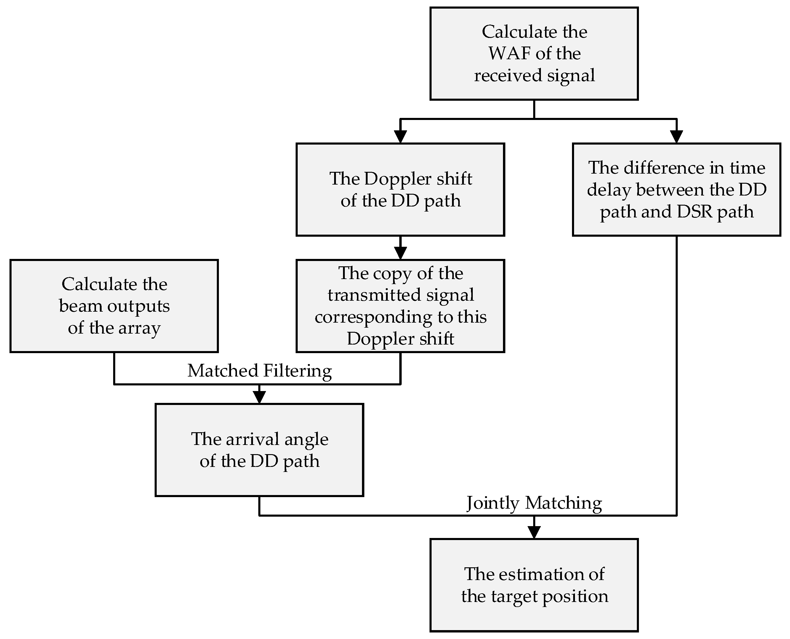
The flowchart of the detection and localization algorithm for moving targets in deep water is shown in Figure 5, and the detailed procedures of this algorithm are as follows:
(1) After determining the transmitted signal s ( t ) and the motion parameters of the target and the acoustic field, the echoes of the moving target and reverberation in the time domain at the receiving point can be calculated using Equations (15) and (22), respectively. Then, the received signal x ( r s , r ; t ) is given by Equation (23).
(2) First, the received signal x ( r s , r ; t ) is subjected to “baseband processing” [26], followed by the calculation of its WAF. Reverberation and echoes can be separated in the Doppler shift domain of the WAF to achieve the detection of the target. Based on this, differences in the time delay of echoes corresponding to different incident–outgoing paths are used to identify the target echoes along each path. Then, one can obtain the Doppler shift ξ 1 of target echoes of the DD path, as well as the difference in time delay between the target echoes of the DD path and the DSR path.
The WAF, as a tool for performance characterization of the transmitted signals, is also commonly used for Doppler analysis of received signals, and is given by [12]
χ ( τ , α ) = x ( r s , r ; t ) s α ( t τ ) d t ,
where s α ( t ) = α s ( α t ) is the time-compressed or -dilated version of the transmitted signal s ( t ) , with α being the compression or dilation ratio, also known as the Doppler factor, and “ ” representing the complex conjugate operator. τ is the time delay of the propagation. In practice, Doppler factors are typically very close to 1. It is more intuitive to display the WAF using the Doppler shift ξ = ( 1 α ) f c relative to the center frequency f c , thus denoting it as χ ( τ , ξ ) . In this process, due to the presence of the carrier wave, directly calculating the WAF of the received signal involves a high computational load, which does not affect the extraction of the WAF envelope. Thus, before processing, the signal’s center frequency can be shifted to 0 Hz, implementing down-sampling for the signal, which is known as “baseband processing”. Baseband processing can significantly reduce the complexity of the WAF calculation.
Interface reverberation is a stationary interference relative to a fixed-position active sonar with a zero Doppler shift, while the target moves relative to the sonar with a certain Doppler shift. Therefore, by exploiting the difference in motion characteristics between the target and the reverberation, target echoes can be detected and separated from reverberation in the Doppler shift domain of the WAF.
As described in Section 2.2, the time delays of echoes corresponding to the three main incident–outgoing paths (DD, DSR, SRSR) are different, ordered from shortest to longest as follows: DD, DSR, and SRSR. Thus, based on the separation of echoes and reverberation, the echoes corresponding to each path can be identified in the time delay domain of the WAF by the order of their arrival times, along with their Doppler shifts. The Doppler shift of echoes of the DD path is ξ 1 , with the copy of the transmitted signal at this shift denoted as s α 1 ( t ) = s ( α 1 t ) . The difference in time delay between the target echoes of the DD path and the DSR path is τ ^ .
(3) The beam outputs of the array at different angles are calculated, and matched filtering is performed with s α 1 ( t ) , with the copy of the transmitted signal corresponding to the Doppler shift of echoes of the DD path identified in step (2). And the arrival angle of this path is then determined as the angle associated with the peak value in the result for matched filtering.
Conventional beamforming (CBF) is performed on the array’s received signals to obtain the time-domain beam outputs P B ( t , θ ) at different angles θ . Then, matched filtering is applied with s α 1 ( t ) , yielding the analytical signal:
y ( τ , θ ) = + P B ( t , θ ) s α 1 ( t τ ) d t .
The arrival angle of echoes of the DD path θ ^ can then be determined as the angle corresponding to the peak value of the time delay–azimuth function y ( τ , θ ) .
(4) In the given acoustic field, the difference in time delay τ ^ between the target echoes of the DD path and the DSR path, as well as the arrival angle θ ^ of echoes of the DD path, are jointly matched with template values of these two quantities for the positions of various assumed targets. The assumed position that provides the optimal match is then used as the estimated position, thereby achieving the target localization.
By combining the sound speed profile of seawater, the template values of the difference in time delay τ ( z s , r s ) between the target echoes of the DD path and the DSR path are calculated at various assumed target depths and ranges, as well as the template values for the arrival angle θ ( z s , r s ) of echoes of the DD path. These two template values are then jointly matched with τ ^ and θ ^ [27]. The cost function for the joint estimation of the target’s depth and range is defined as:
E ( z s , r s ) = 10 log 10 ( | τ ^ τ ( z s , r s ) | × | θ ^ θ ( z s , r s ) | ) .
Therefore, the depth and range corresponding to the maximum value of this function are taken as the estimated position of the target.

3.2. Simulation Analysis

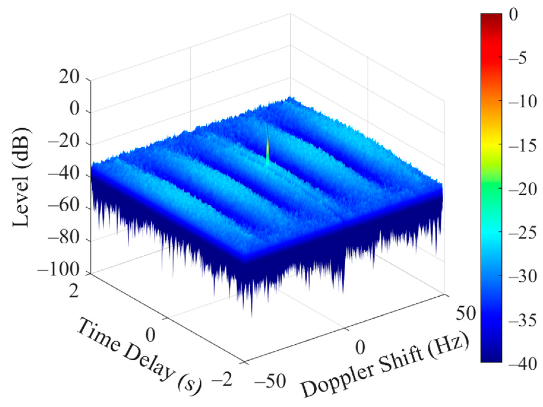
The pseudorandom code phase-modulated (PCPM) signal is widely used in active detection due to its good resolution in time delay and Doppler shift, and this paper also selects it as the transmitted signal. The PCPM signal consists of multiple CW sub-pulses, each expressed as x ( t ) = exp { j [ 2 π f c t + π b ( t ) ] } , where f c is the center frequency and b ( t ) is the phase-modulated function controlled by an m-sequence, taking values of 0 and 1. The parameters of the PCPM signal used in this paper are as follows: center frequency f c = 3   kHz , bandwidth B = 500   Hz , pulse width T = 4.09   s , and m-sequence length 2047. After normalizing according to the signal’s energy, the WAF of the transmitted signal is shown in Figure 6. As seen in Figure 6, the main lobe of the WAF exhibits a pin-shaped pattern, indicating the excellent resolution in terms of time delay and Doppler shift. Moreover, the lower center frequency of this signal makes it suitable for long-range propagation in deep water. Therefore, this signal is chosen as the transmitted signal.
Without loss of generality, this paper conducts simulations under the Munk sound speed profile in deep water, with the sea depth set to 5000 m, the depth of the sound channel axis to 1100 m, and the mixing layer depth to 0 m. A rigid sphere with a radius of 5 m moves horizontally at a speed of −5 m/s (the negative sign indicates that the target moves away from the source). The target depth is set to 200 m, and the horizontal distance between the sonar and the target is 8 km. The vertical array with 16 elements receives signals at the sea bottom, with element spacing of 0.25 m. The depth of the element closest to the sea bottom is 4990 m. The source is collocated with the array, and its depth is same as that of the shallowest element of the vertical array. The sound speed and densities of the seawater and seabed are as shown in Figure 7, and their absorption parameters, μ 1 and μ , are referenced from [17].
In this paper, the signal-to-reverberation ratio (SRR) is defined as the ratio of the echo energy to the reverberation energy within the time period of the target echo’s arrival. It can be expressed in logarithmic form as:
SRR = 10 log 10 n = n 1 n 2 | p echo ( r s , r ; n ) | 2 n = n 1 n 2 | p rev ( n ) | 2 ,
where p echo ( r s , r ; n ) and p rev ( n ) represent the discrete-time target echo and reverberation, respectively, while n 1 and n 2 are the sample points marking the start and end times of the target echo’s arrival.
The simulation processes of the algorithm for the detection and localization of the moving target in deep water are as follows:
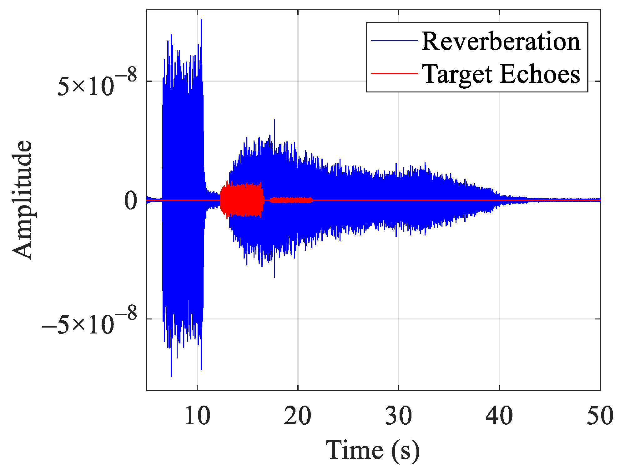
Step 1: Given the above transmitted signal and the sound field, the received signal x ( r s , r ; t ) can be calculated by Equation (23), and its waveform is shown in Figure 8. At this point, the SRR of the received signal is −7 dB. It can be seen that the target echoes overlap with the reverberation at the arrival time, making it impossible to separate the two in the time domain.
Step 2: First, “baseband processing” is performed on the received signal x ( r s , r ; t ) and its WAF is calculated, as shown in Figure 9. It can be observed that a target echo with a Doppler shift of approximately −17 Hz is detected in the Doppler shift domain of the WAF, successfully separating it from the reverberation, which has a Doppler shift of 0 Hz.
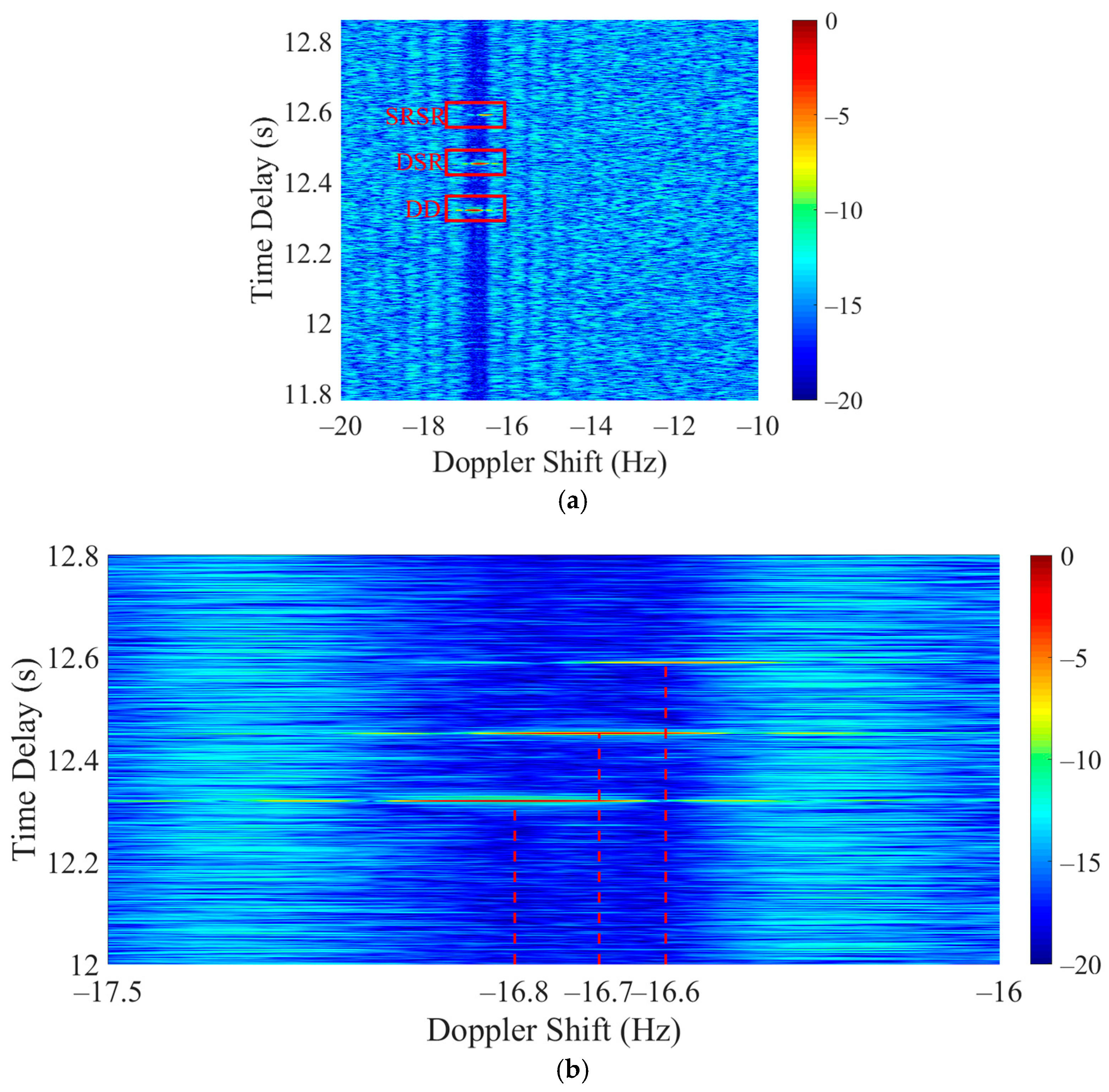
The two-dimensional image of the WAF for the received signal and its zoomed-in view are shown in Figure 10. In Figure 10a, the target echoes corresponding to the three main incident–outgoing paths (DD, DSR, and SRSR) are distinguished by differences in their time delays, and the difference in time delay between the target echoes of the DD and DSR paths is τ ^ . In Figure 10b, the Doppler shifts of the target echoes for these three paths differ, with the Doppler shift of the target echo for the DD path being ξ 1 . And the copy of the transmitted signal at this Doppler shift is denoted as s α 1 ( t ) .
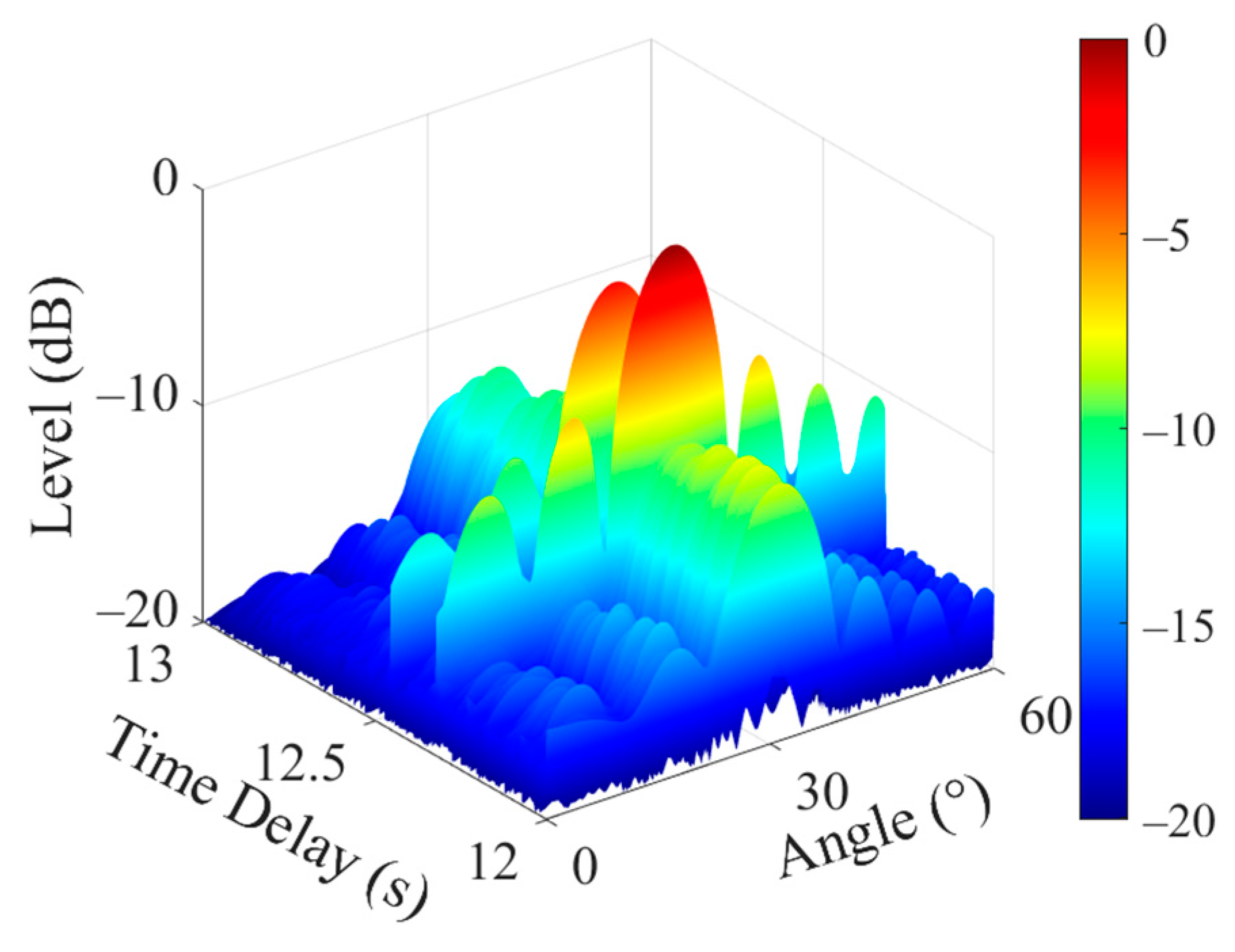
Step 3: CBF is performed on the vertical array’s received signals to obtain the time-domain beam outputs P B ( t , θ ) at different angles. Then, matched filtering is conducted between P B ( t , θ ) and s α 1 ( t ) , and the analytical signal y ( τ , θ ) is shown in Figure 11 as the result. It can be observed that the time delay–azimuth function reaches its maximum at an angle of 31°, thus providing an estimated arrival angle θ ^ of 31° for the echoes of the DD path.
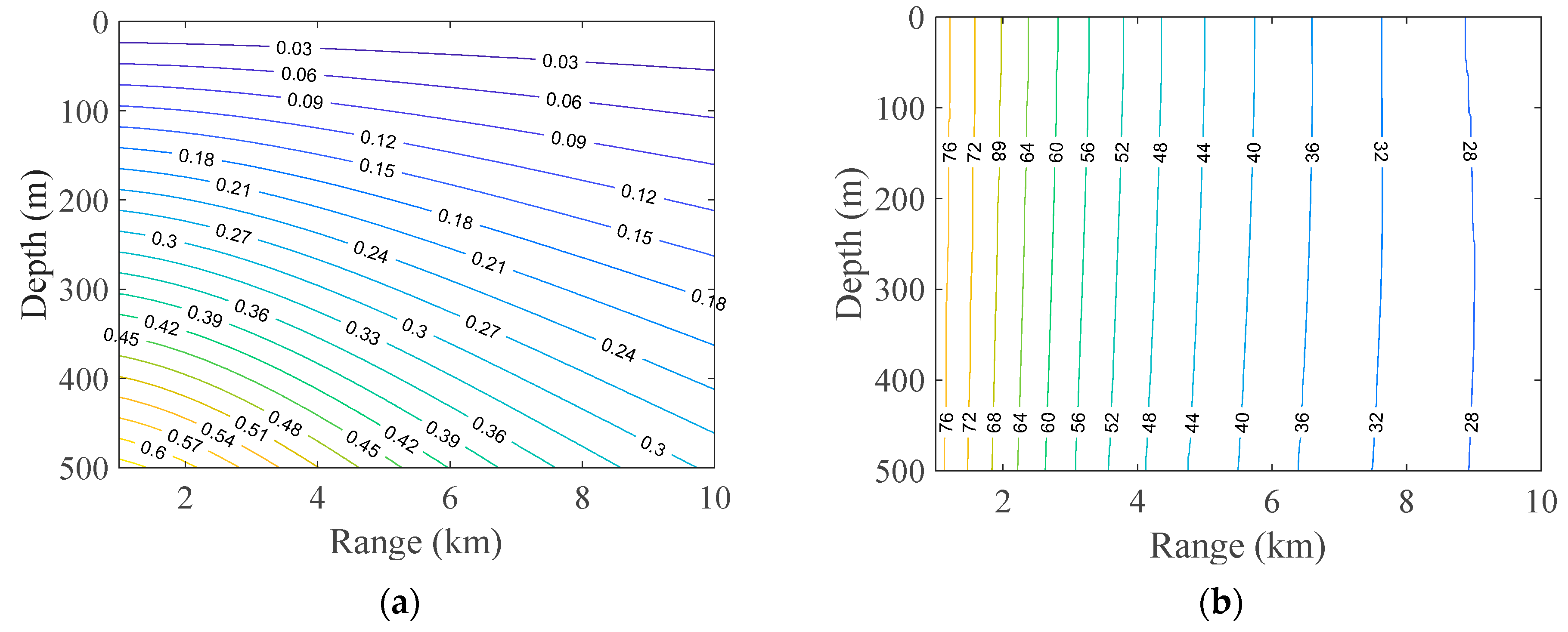
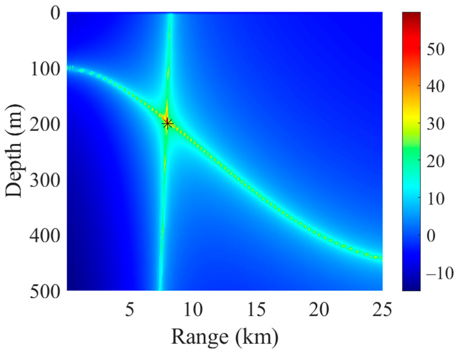
Step 4: Given the acoustic field, the contour plots of the difference in time delay τ ( z s , r s ) between the target echoes of the DD path and the DSR path, as well as the arrival angle θ ( z s , r s ) of echoes of the DD path, at various target positions are shown in Figure 12a,b, respectively. Here, z s is the target depth, and r s is the horizontal distance between the target and the sonar.
Figure 12a shows that τ ( z s , r s ) is sensitive to changes in target depth, making it useful for depth estimation, although it may introduce ambiguity in range estimation. Conversely, Figure 12b shows that θ ( z s , r s ) is sensitive to changes in target range, making it effective for range estimation, but it may be ambiguous in depth estimation. Therefore, by using the results of both τ ( z s , r s ) and θ ( z s , r s ) for target localization, one can compute the cost function using Equation (26), as shown in Figure 13. The intersection of the two curves indicates the maximum value of the cost function, and the corresponding depth and range at this intersection represent the estimated target position. The label “” in Figure 13 indicates the true target position. It can be seen that both the target depth and range are accurately estimated.

4. Performance Analysis

In Section 3, the simulation result based on the Munk sound speed profile validates the effectiveness of the proposed method of detection and localization for moving targets in deep water. In this section, a series of numerical simulations is conducted to further analyze the performance of this method as it varies with changes in target depth, horizontal distance between the sonar and the target, target velocity, and SRR. The transmitted signal and the acoustic field are the same as those described in Section 3.
The performance of the localization method is reflected in the estimation of both target depth and target range. To quantitatively describe the localization performance, the relative error of range estimation (RERE) and the relative error of depth estimation (REDE) are typically used as evaluation metrics [28], and their definitions are as follows:
e RERE = | r s r ^ s | r s ,
e REDE = | z s z ^ s | z s ,
where z s and r s are the true values of target depth and horizontal distance between the target and the sonar, respectively, while z ^ s and r ^ s denote their corresponding estimated values. The smaller the RERE and REDE, the more accurate the estimation of the target position, indicating better localization performance.

4.1. Target Depth

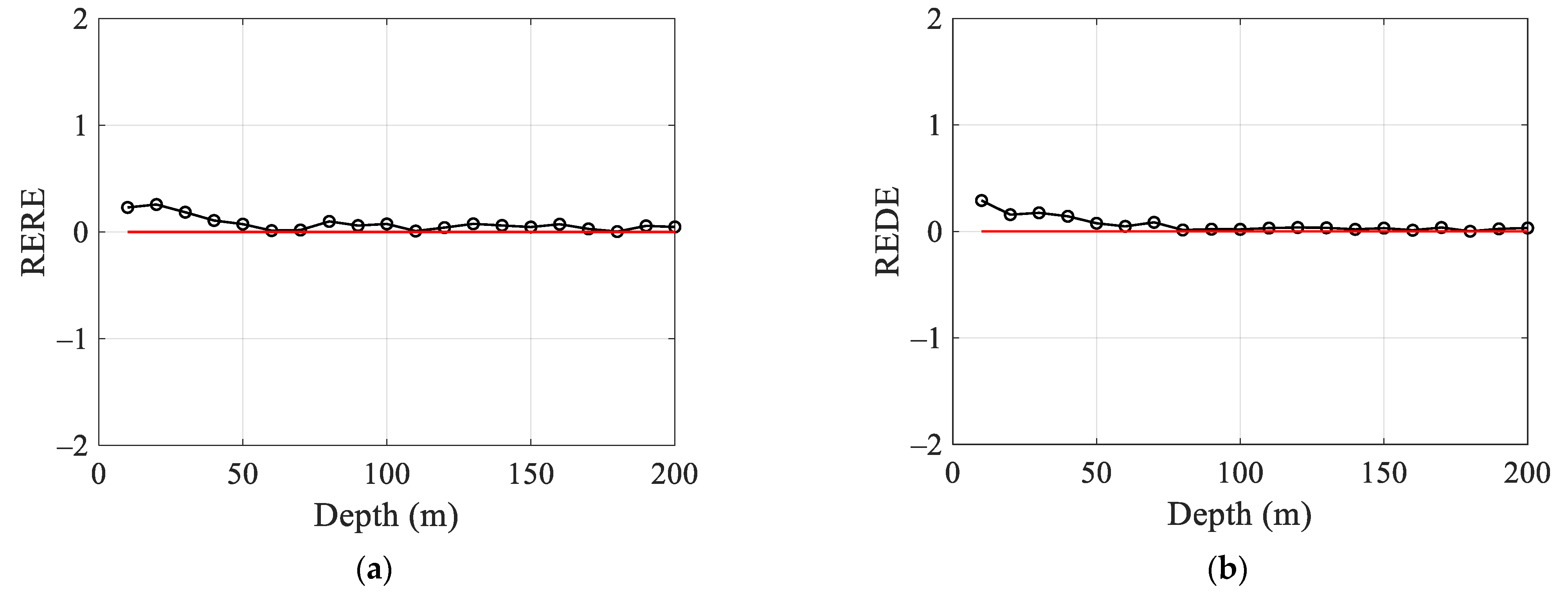
In the following simulations of the target localization, the horizontal distance between the sonar and the target is set at 10 km, and the target velocity is set to −5 m/s. The target depth varies within a range of 10 m to 200 m, and the curves showing the RERE and REDE as functions of target depth are displayed in Figure 14.
Figure 14 shows that, when the target depth is relatively shallow (in the range of 10 m to 40 m), the RERE and REDE are larger. This is because, at shallow depths, the difference in time delay between the target echoes of the DD path and the DSR path is very small, making the localization result highly sensitive to small estimation errors regarding the time delay, which degrades the performance. As the target depth increases, the difference in time delay between these two paths becomes larger, reducing the impact of estimation errors regarding the time delay. Consequently, the RERE and REDE decrease, and the performance of the localization improves.
Therefore, with other target parameters remaining constant, the localization error of this method is relatively large when the target depth is shallow. However, as the target depth increases, the localization performance stabilizes and does not exhibit significant variation.

4.2. Horizontal Distance Between the Sonar and the Target

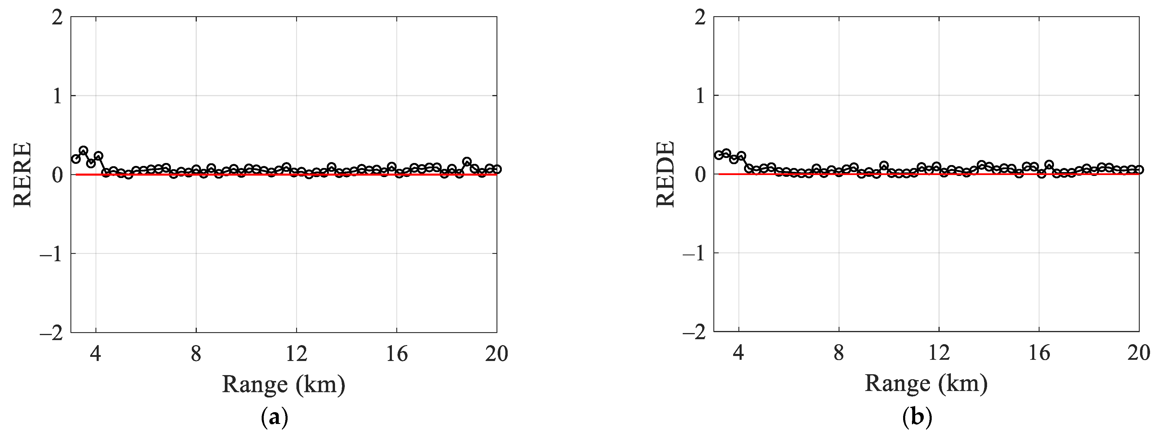
In the following simulations of the target localization, the target depth is set at 100 m, and the target velocity is set to −5 m/s. The horizontal distance between the sonar and the target varies within a range of 3 km to 20 km, and the RERE and REDE, as functions of the horizontal distance, are shown in Figure 15.
Figure 15 shows that the RERE and REDE are relatively large when the distance between the target and the sonar is around 4 km. This is because, at this distance, the arrival time of the target echo coincides with that of the seabed reverberation after a single surface reflection, and the energy of reverberation near this time is significantly higher than that of the target echo. This results in increased error in estimating the arrival angle of echoes of the DD path during CBF, ultimately leading to greater localization error. As the distance increases, the arrival time of the target echo also increases, and the energy of reverberation decreases correspondingly. The reverberation energy near the arrival time of echoes is still greater than that of the target echo, but the difference becomes smaller, reducing the impact of reverberation on target localization. Although localization errors increase slightly at certain long distances, the overall performance for the localization remains satisfactory.
Therefore, with other target parameters unchanged and only the distance between the sonar and the target varying, the localization error of this method becomes larger if the arrival time of the target echo falls near that of seabed reverberation after a single surface reflection. Beyond this time window, the performance does not change significantly with the increase in distance.

4.3. Target Velocity

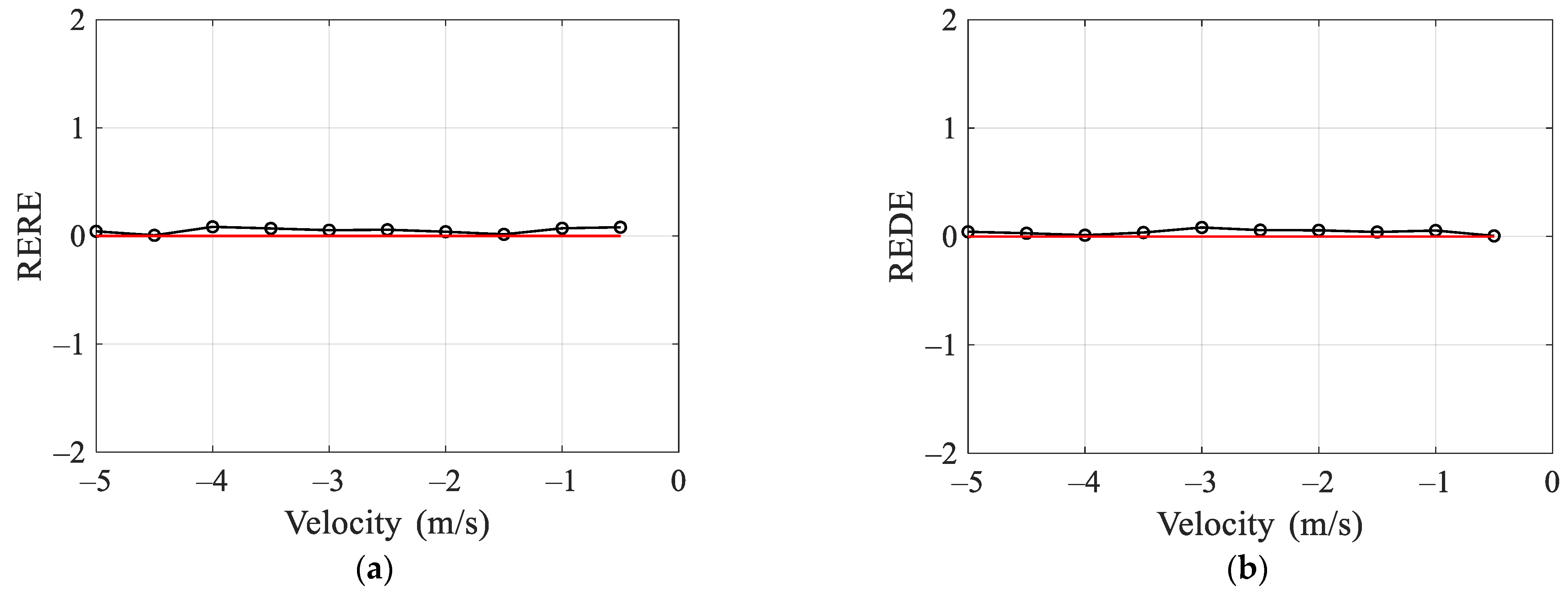
In the following simulations of the target localization, the horizontal distance between the sonar and the target is set at 10 km, and the target depth is set at 100 m. The target velocity varies within a range of −5 m/s to −0.5 m/s, and the RERE and REDE as functions of target velocity are displayed in Figure 16.
Figure 16 shows that, with other target parameters remaining constant, variations in target velocity do not significantly affect the RERE and REDE. This is because, in this method, target velocity only influences the Doppler shift of the target echoes of the DD path, and the estimation error of this shift is independent of its value. Therefore, changes in target velocity do not substantially impact localization performance.

4.4. SRR

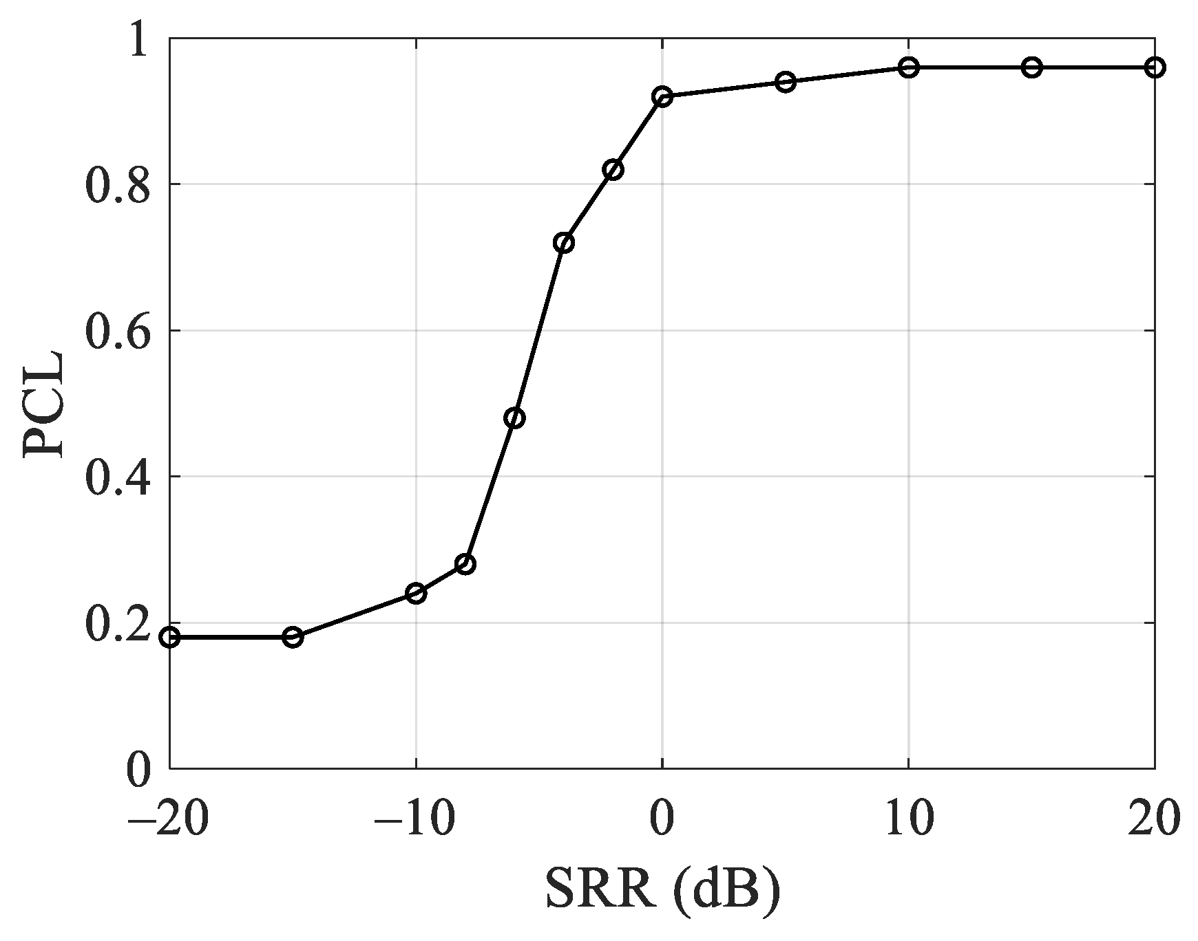
In the following simulations of the target localization, received signals with varying SRR are considered. The horizontal distance between the sonar and the target is set at 10 km, the target depth is set at 100 m, and the target velocity is set to −5 m/s. To quantitatively compare the performance under different SRRs, the probability of credible localization (PCL) is defined as [29,30]:
PCL = 1 N t e s t i = 1 N t e s t η i ,
η i = { 1 , | r s r ^ s | 0.5   km , | z s z ^ s | 20   m 0 , otherwise ,
where N t e s t is the number of simulations; z s and r s are the true values of target depth and horizontal distance between the target and the sonar, respectively; and z ^ s and r ^ s denote the estimated results. After 50 Monte Carlo simulations, the variation in PCL for the proposed method under different SRRs is shown in Figure 17.
As observed from the trend of the curve in Figure 17, since reverberation affects the estimation results of both the difference in time delay and arrival angles, the PCL begins to improve when the SRR exceeds −10 dB. With the increase in SRR, the method achieves high-accuracy localization results when the SRR is above approximately 0 dB.

5. Conclusions

Active detection in deep water involves the long-distance propagation of the signal, with a pronounced multipath arrival structure. In addition, reverberation, as the background interference in active sonars, exhibits more complex temporal variations (often with periodic structures) in deep water. This presents significant differences from the working conditions of active sonars in shallow water with short-range propagation. For the detection and localization of the moving target in deep water under reverberation, the contributions of this paper are as follows:
(1) We establish a model for active sonars’ received signals in deep water. First, using the ray-Kirchhoff approximation method, a matrix-form formula for the scattered sound field of targets in the frequency domain is presented (Section 2.1, Equation (10)). Then, in the direct sound zone, Doppler factors for different multipaths due to target motion are analyzed (Section 2.2, Equations (16) and (20)), and these factors are incorporated into the scattered sound field to obtain the echoes of moving targets in deep water (Section 2.2, Equation (15)). Next, based on the ray theory and the mesh method, the time-domain waveforms of seabed reverberation are provided (Section 2.3, Equation (21)). Finally, the signal received by active sonars in deep water under reverberation is derived (Section 2.3, Equation (23)). This model offers a foundation for research on active sonars in deep water.
(2) We propose a method for detection and localization of the moving targets in deep water. Firstly, the WAF of the received signals is calculated. In the Doppler shift domain of the WAF, one can separate the target echoes from the reverberation to achieve the detection of the target. Then, based on the differences in the time delays of echoes corresponding to different paths, one can obtain the Doppler shift ξ 1 of the target echoes of the DD path, as well as the difference in time delay τ ^ between the DD path and the DSR path. Next, the beam outputs of the array are calculated, and matched filtering is performed with the copy of the transmitted signal corresponding to the Doppler shift ξ 1 . The arrival angle of the DD path θ ^ is then determined as the angle associated with the peak value in the matched filtering result (Section 3.1, Equation (25)). Finally, in the given acoustic field, τ ^ and θ ^ are jointly matched with template values of these two quantities for various assumed targets’ positions. The assumed position that provides the optimal match is then used as the estimated position, thereby achieving target localization.
(3) We analyze the performance of this method. The performance varies with changes in target depth, horizontal distance between the sonar and the target, target velocity, and SRR. Given the sound field in this paper, the localization error is relatively large when the target depth is shallow (in the range of 10 m to 40 m). As for the horizontal distance between the sonar and the target, if the arrival time of the target echo falls near that of seabed reverberation after a single surface reflection, the performance degrades. And changes in target velocity do not substantially influence the performance. With the increase in SRR, the accuracy of localization begins to improve when the SRR exceeds −10 dB and reaches an excellent level when the SRR is above approximately 0 dB.

Author Contributions

Conceptualization, J.D. and S.Z.; methodology, J.D., S.Z., and Y.Q.; software, J.D., S.Z., Y.Q., and C.L.; validation, J.D. and S.Z.; formal analysis, J.D. and S.Z.; investigation, J.D. and S.Z.; resources, S.Z., Y.Q., and C.L.; data curation, J.D.; writing—original draft preparation, J.D.; writing—review and editing, S.Z., C.L., Y.Q., and J.D.; visualization, J.D.; supervision, S.Z., Y.Q., and C.L.; project administration, S.Z.; funding acquisition, S.Z., Y.Q., and C.L. All authors have read and agreed to the published version of the manuscript.

Funding

This research was funded by the China Postdoctoral Science Foundation, Grant No. GZC20232903, Young Scientists Fund of the National Natural Science Foundation of China, Grant No. 12404519, and the Special Research Assistant Program of the Chinese Academy of Sciences and National Natural Science Foundation of China, Grant Nos. 12174419 and 11804362.

Institutional Review Board Statement

Not applicable.

Informed Consent Statement

Not applicable.

Data Availability Statement

Data are contained within the article.

Acknowledgments

The author would like to thank the reviewers for their comments on improving the quality of this paper.

Conflicts of Interest

The authors declare no conflicts of interest.

References

  1. Zhang, M.; Wang, H.; Wang, J. Research on detection methods of echo under reverberation condition. In Proceedings of the 2019 Conference of the Underwater Acoustics Branch of the Acoustical Society of China, Nanjing, China, 24–26 May 2019. [Google Scholar]
  2. Yan, S.; Ma, X. Designs and implementations of broadband beamformers. Acta Acust. 2008, 33, 316–326. [Google Scholar] [CrossRef]
  3. Li, X.; Ma, X.; Hao, C.; Yan, S. Wideband reverberation suppression in beams domain by utilizing angular distribution features. Acta Acust. 2018, 43, 738–744. [Google Scholar] [CrossRef]
  4. Kou, S.; Feng, X.; Huang, H.; Bi, Y. A Space-Time Adaptive Processing Method Based on Sparse Reconstruction of Reverberation Interference. J. Northwest. Polytech. Univ. 2021, 38, 1179–1187. [Google Scholar] [CrossRef]
  5. Yang, Z.; de Lamare, R.C.; Liu, W. Sparsity-based STAP using alternating direction method with gain/phase errors. IEEE Trans. Aerosp. Electron. Syst. 2017, 53, 2756–2768. [Google Scholar] [CrossRef]
  6. Zhu, Y.; Yang, K.; Duan, R.; Wu, F.; Zhang, M. Sparse spatial spectral estimation with heavy sea bottom reverberation in the fractional fourier domain. Appl. Acoust. 2020, 160, 107132. [Google Scholar] [CrossRef]
  7. Li, X.; Yang, Y.; Meng, X. Morphological characteristics separation of underwater target echo and reverberation in time and frequency domain. Acta Acust. 2017, 42, 169–177. [Google Scholar] [CrossRef]
  8. Li, X.; Xia, Z.; Wang, X.; Mu, L. Blind separation of underwater target echoes in reverberation background. J. Harbin. Eng. Univ. 2015, 36, 62–67. [Google Scholar] [CrossRef]
  9. Steinberg, J.C. Underwater Sound Propagation in the Straits of Florida. J. Acoust. Soc. Am. 1966, 39, 301–315. [Google Scholar] [CrossRef]
  10. Jourdain, G.; Henrioux, J.P. Use of large bandwidth-duration binary phase shift keying signals in target delay Doppler measurements. J. Acoust. Soc. Am. 1995, 90, 299–309. [Google Scholar] [CrossRef]
  11. Colin, M.E.G.D.; Beerens, S.P. False-alarm reduction for low-frequency active sonar with BPSK pulses: Experimental results. IEEE J. Ocean. Eng. 2011, 36, 52–59. [Google Scholar] [CrossRef]
  12. Yang, T.C.; Schindall, J.; Huang, C.F.; Liu, J.Y. Clutter reduction using Doppler sonar in a harbor environment. J. Acoust. Soc. Am. 2012, 132, 3053–3067. [Google Scholar] [CrossRef]
  13. Zheng, H.; Li, Z. Realization of low frequency reverberation sequence in shallow water based on normal-mode theory. J. Appl. Acoust. 2012, 31, 272–276. [Google Scholar] [CrossRef]
  14. Wang, L.; Qin, J.; Fu, D.; Li, Z.; Liu, J.; Weng, J. Bottom reverberation for large receiving depth in deep water. Acta Phys. Sin. 2019, 68, 134303. [Google Scholar] [CrossRef]
  15. Huang, S.; Fang, S.; Han, N. Analysis of Doppler factor based on multi-path sound channel. In Proceedings of the 2017 INTER-NOISE and NOISE-CON Congress and Conference, Hong Kong, China, 27–30 August 2017; Available online: http://www.proceedings.com/37265.html (accessed on 7 December 2017).
  16. Tang, W.; Fan, J.; Ma, Z. Acoustic Scattering of Underwater Targets; Science Press: Beijing, China, 2018; pp. 32–35. ISBN 978-7-03-054027-0. [Google Scholar]
  17. Chen, Y.; Tang, W.; Fan, J. The geometrical acoustic method for calculating the echo of targets submerged in a shallow water waveguide. Acta Acust. 2010, 35, 335–342. [Google Scholar] [CrossRef]
  18. Porter, M.B.; Bucker, H.P. Gaussian beam tracing for computing ocean acoustic fields. J. Acoust. Soc. Am. 1987, 82, 1349–1359. [Google Scholar] [CrossRef]
  19. Jensen, F.B.; Kuperman, W.A.; Porter, M.B.; Schmidt, H. Computational Ocean Acoustics; Springer New York: New York, USA, 2011; pp. 133–135. ISBN 978-7-118-11202-3. [Google Scholar]
  20. Kirkup, S. The Boundary Element Method in Acoustics: A Survey. Appl. Sci. 2019, 9, 1642. [Google Scholar] [CrossRef]
  21. Zhang, X.; Song, K.; Li, C.; Yang, L. Parameter Estimation for Multi-Scale Multi-Lag Underwater Acoustic Channels Based on Modified Particle Swarm Optimization Algorithm. IEEE Access 2017, 5, 4808–4820. [Google Scholar] [CrossRef]
  22. Peterson, J.C.; Porter, M.B. Ray/Beam Tracing for Modeling the Effects of Ocean and Platform Dynamics. IEEE J. Ocean. Eng. 2013, 38, 655–665. [Google Scholar] [CrossRef]
  23. Munk, W.H. Sound channel in an exponentially stratified ocean, with application to SOFAR. J. Acoust. Soc. Am. 1974, 55, 220–226. [Google Scholar] [CrossRef]
  24. Ellis, D.D. A shallow-water normal-mode reverberation model. J. Acoust. Soc. Am. 1995, 97, 2804–2814. [Google Scholar] [CrossRef]
  25. Wu, D.; Huang, Y. Geometric model of the waveform prediction for the deep-ocean reverberation. In Proceedings of the 2015 Conference of the Underwater Acoustics Branch of the Acoustical Society of China, Wuhan, China, 5–8 June 2015. [Google Scholar]
  26. Abraham, D.A. Underwater Acoustic Signal Processing: Modeling, Detection, and Estimation; Springer: Cham, Switzerland, 2019; pp. 367–375. [Google Scholar] [CrossRef]
  27. Qi, Y.; Zhou, S.; Luo, Z.; Liu, C.; Du, S.; Dun, J.; Zhou, L. Passive source localization based on multipath arrival angles with a vertical line array using sparse Bayesian learning. J. Acoust. Soc. Am. 2023, 153, 773–791. [Google Scholar] [CrossRef]
  28. Dubrovinskaya, E.; Nissen, I.; Casari, P. On the accuracy of passive multipath-aided underwater range estimation. In Proceedings of the 2016 IEEE Third Underwater Communications and Networking Conference (UComms), Lerici, Italy, 30 August–1 September 2016. [Google Scholar] [CrossRef]
  29. Duan, R.; Yang, K.; Ma, Y.; Lei, B. A reliable acoustic path: Physical properties and a source localization method. Chin. Phys. B 2012, 21, 124301. [Google Scholar] [CrossRef]
  30. Liu, Y.; Niu, H.; Yang, S.; Li, Z. Multiple source localization using learning-based sparse estimation in deep ocean. J. Acoust. Soc. Am. 2021, 150, 3773–3786. [Google Scholar] [CrossRef]
Figure 1. Transmission and reception models for the edges of the transmitted pulse. (a) The front edge. (b) The back edge.
Jmse 12 02360 g001
Figure 2. Schematic of the simplified calculation.
Jmse 12 02360 g002
Figure 3. Theoretical and calculated values of Doppler factors for different paths as a function of the horizontal distance between the sonar and the target. (a) DD. (b) DSR. (c) SRSR.
Jmse 12 02360 g003
Figure 4. Schematic of the mesh method.
Jmse 12 02360 g004
Figure 5. Flowchart of the detection and localization algorithm for moving targets in deep water.
Jmse 12 02360 g005
Figure 6. WAF of the transmitted signal.
Jmse 12 02360 g006
Figure 7. Schematic of the sound field.
Jmse 12 02360 g007
Figure 8. Waveform of the received signal.
Jmse 12 02360 g008
Figure 9. WAF of the received signal.
Jmse 12 02360 g009
Figure 10. WAF as a function of time delay and Doppler shift. (a) A 2D pseudo-color map. (b) A color plot zooming in the echoes.
Jmse 12 02360 g010
Figure 11. Image of the analytical signal y ( τ , θ ) .
Jmse 12 02360 g011
Figure 12. The contour plots of (a) the difference in time delay between the target echoes of the DD path and the DSR path, and (b) the arrival angle of echoes of the DD path.
Jmse 12 02360 g012
Figure 13. Cost function for the joint estimation of the target’s depth and range. The label “∗” indicates the true target position.
Jmse 12 02360 g013
Figure 14. (a) RERE and (b) REDE as functions of the target depth. The red lines represent the zero-error lines, while the dots lines denote the error curves.
Jmse 12 02360 g014
Figure 15. (a) RERE and (b) REDE as functions of the target range. The red lines represent the zero-error lines, while the dots lines denote the error curves.
Jmse 12 02360 g015
Figure 16. (a) RERE and (b) REDE as functions of the target velocity. The red lines represent the zero-error lines, while the dots lines denote the error curves.
Jmse 12 02360 g016
Figure 17. PCL as a function of SRR.
Jmse 12 02360 g017
Disclaimer/Publisher’s Note: The statements, opinions and data contained in all publications are solely those of the individual author(s) and contributor(s) and not of MDPI and/or the editor(s). MDPI and/or the editor(s) disclaim responsibility for any injury to people or property resulting from any ideas, methods, instructions or products referred to in the content.