Abstract
Collaborative operations of multiple AUVs have been becoming increasingly popular and efficient in underwater tasks of marine applications. Autonomous navigation capability and cooperative control stability of multiple AUVs are crucial and challenging issues in underwater environments. To address the collaborative problem of path planning for multiple AUVs, this paper proposes an adaptive multi-population particle swarm optimization (AMP-PSO). In AMP-PSO, we design a grouping strategy of multi-population and an exchanging mechanism of particles between groups. We separate particles into one leader population and various follower populations according to their fitness. Firstly, in the grouping strategy, particles within the leader population are updated by both the leader population and follower populations so as to keep global optimization, while particles within the follower population are updated by their own group so as to keep local priority. Secondly, in the exchanging mechanism, particles are exchanged between the leader population and follower populations so as to improve multi-population diversity. To accommodate multi-population characteristics, an adaptive parameter configuration is also included to enhance the global search capability, convergence speed, and complex environment adaptability of AMP-PSO. In numerical experiments, we simulate various scenarios of collaborative path planning of multiple AUVs in an underwater environment. The simulation results convincingly demonstrate that AMP-PSO can obtain feasible and optimal path solutions compared to classic PSO and other improved PSO, which enable multiple AUVs to effectively achieve objectives under the conditions of collision avoidance and navigation constraint.
1. Introduction
In recent years, autonomous underwater vehicles (AUVs) have been becoming increasingly popular in wide range of marine applications [1,2]. With widespread applications across civilian, military, and commercial sectors, AUVs are playing a crucial role in various domains such as underwater exploration and maritime surveillance [3,4]. The increasing enhancements of AUV performance, functionalities, and intelligence significantly extend the operational capabilities of surface and underwater tasks [5,6]. However, single AUVs still have the obvious limitations of energy supply and payload capacity during complex tasks [7,8]. Collaboration of multiple AUVs has become a significant research direction to address these limitations [9,10].
Within collaborative systems of multiple AUVs, collaborative path planning emerges as a highly significant issue to guide a group of AUVs to reach designated target locations along collision-free paths of coordinated collaboration among the AUVs [11]. Collaborative operations of multiple AUVs not only need to consider the shortest path, minimum time cost, and energy consumption of individual AUV, but also involve multi-objective optimization of multiple AUVs considering internal collision avoidance and external risk control [12,13]. Collaborative path planning of multiple AUVs is challenging due to the dynamic environments and complex tasks, which require coordinating the movements of AUVs to avoid collisions and simultaneously optimize overall task [14].
To consider both local avoidance and global optimization, Zeng et al. [15] and Youakim et al. [16] conducted comparisons and categorizations of various path-planning methods, such as artificial potential field (APF) methods, sampling-based methods, and search-based methods. The multi-point potential field method (MPPF), as a variant of APF, shares the efficient and rapid characteristics of APF, but it is susceptible to convergent local optimization [17]. Rapidly-exploring random trees (RRTs), as a classic sampling-based method, has an impact on the effectiveness of cost reduction and performance optimization in high-dimensional and time-constrained path-planning scenarios [18]. Genetic algorithm (GA), as a classic search-based method, is capable of generating optimal and robust paths via a heuristic approach [19]. However, there is the limitation of computational efficiency when GA deals with complex problems. Hermand et al. [20] employed an explicit reference governor (ERG) framework to control drones within a geo-fenced area, ensuring accurate control within a limited range and improving safety. However, the performance may be affected in highly dynamic or chaotic environments. Ru et al. [21] used an approach that included an O-AUV sensing model. This model allowed the AUV to sense omnidirectional areas, which significantly enhanced underwater information acquisition. They also made improvements to the NSGA-II algorithm to develop a trajectory optimization strategy for the accelerated optimization and identification of Pareto optimal solutions. However, the complexity of the omnidirectional sensing model may pose computational challenges. Liu et al. [22] employed model predictive control (MPC) to address intricate path planning issues in dynamic environments. The approach considered vehicle dynamics constraints and the presence of other vehicles. However, the approach might be computationally intensive due to the nonlinear and non-convex nature of the MPC problems. Evolutionary algorithms still demonstrate remarkable performance in addressing path optimality issues, especially when high-dimensional, complex problems are considered [23,24]. Among existing evolutionary algorithms, Zeng et al. [15] highlighted that particle swarm optimization (PSO) exhibits notable robustness and efficiency in addressing high-dimensional path planning problems. The related works studying modification PSO are summarized in Table 1. Panda et al. [25] compared various algorithms’ AUV path optimization strategies based on PSO to clarify their advantages and limitations. The practical application of path optimization algorithms based on PSO strongly relies on appropriate cost functions and different types of constraints. To ensure path smoothness, feasibility, and collision avoidance for AUVs, it is essential to integrate multiple conflicting criteria to achieve optimal control decisions [26]. These criteria involve the following objectives: (i) Avoid collisions by maintaining a safe distance from obstacles; (ii) ensure the path has an adequate number of control points to generate a complete trajectory; and (iii) satisfy AUV minimum turning radius and pitch control limitations.

Table 1.
Previous studies of modification PSO.
In this study, we introduce the adaptive multi-population particle swarm optimization (AMP-PSO) algorithm, a novel approach in the field of autonomous underwater vehicle (AUV) path planning. AMP-PSO employs an innovative grouping strategy and a dynamic exchanging mechanism of particles which are not found in traditional PSO algorithms. The novel combination of proposed AMP-PSO can enhance global search capability, accelerate convergence speed, and improve solution adaptability, particularly in complex and dynamic underwater environments. AMP-PSO overcomes specific limitations which are inherent in existing methods, such as susceptibility to local optimization and difficulty in navigating intricate terrains. AMP-PSO represents a significant advancement in efficient and effective AUV path planning. These advancements directly address the research gaps identified earlier, offering a robust solution to the challenges in current AUV path planning methodologies. Through comparative analysis in simulation experiments, this paper successfully verifies that AMP-PSO achieves the best performance than classic PSO and other improved PSO methods in terms of solving collaborative path planning problem with multiple AUVs. AMP-PSO not only has a relatively low computational cost, but also provides high-quality path-planning solutions. The main contributions of this study are as follows. (i) AMP-PSO includes a distributed strategy of multi-population for the collaborative path planning of multiple AUVs. In AMP-PSO, the leader population can learn from follower populations to improve the search ability in global optimization, while follower populations learn only by themselves to keep local solution exploring as a priority. (ii) AMP-PSO adopts an adaptive configuration of parameter updating to enhance the benefits of multi-population so that adaptive updating rules can increase diversity in the leader population and accelerate convergence in follower populations.
The remaining parts of this paper are organized into four sections. Section 2 provides a detailed description and constraint analysis of collaborative issues concerning multiple AUVs. Section 3 introduces the methodology of AMP-PSO and its application of collaborative path planning for multiple AUVs. Section 4 presents the numerical experiments and simulation results. Section 5 concludes the paper with a summary.
2. Environmental Setting and Experimental Preparation
2.1. Obstacle Setting of Underwater Environment
The underwater environment is crucial to AUV path planning. The navigation path of multiple AUVs is primarily affected by underwater obstacles in the ocean [27]. Therefore, according to impacts on AUVs, we can separate obstacles into two categories: (i) hard obstacles and (ii) soft obstacles. Hard obstacles are mostly artificial objects such as barriers and obstructions submerged under the ocean. AUVs must absolutely avoid these in order to maintain the integrity and reliability of their paths. Soft obstacles are mostly natural organisms such as sestons and particulates floating in the ocean. It is essential to minimize the influence of such obstacles so as to reduce the impact of AUV navigation.
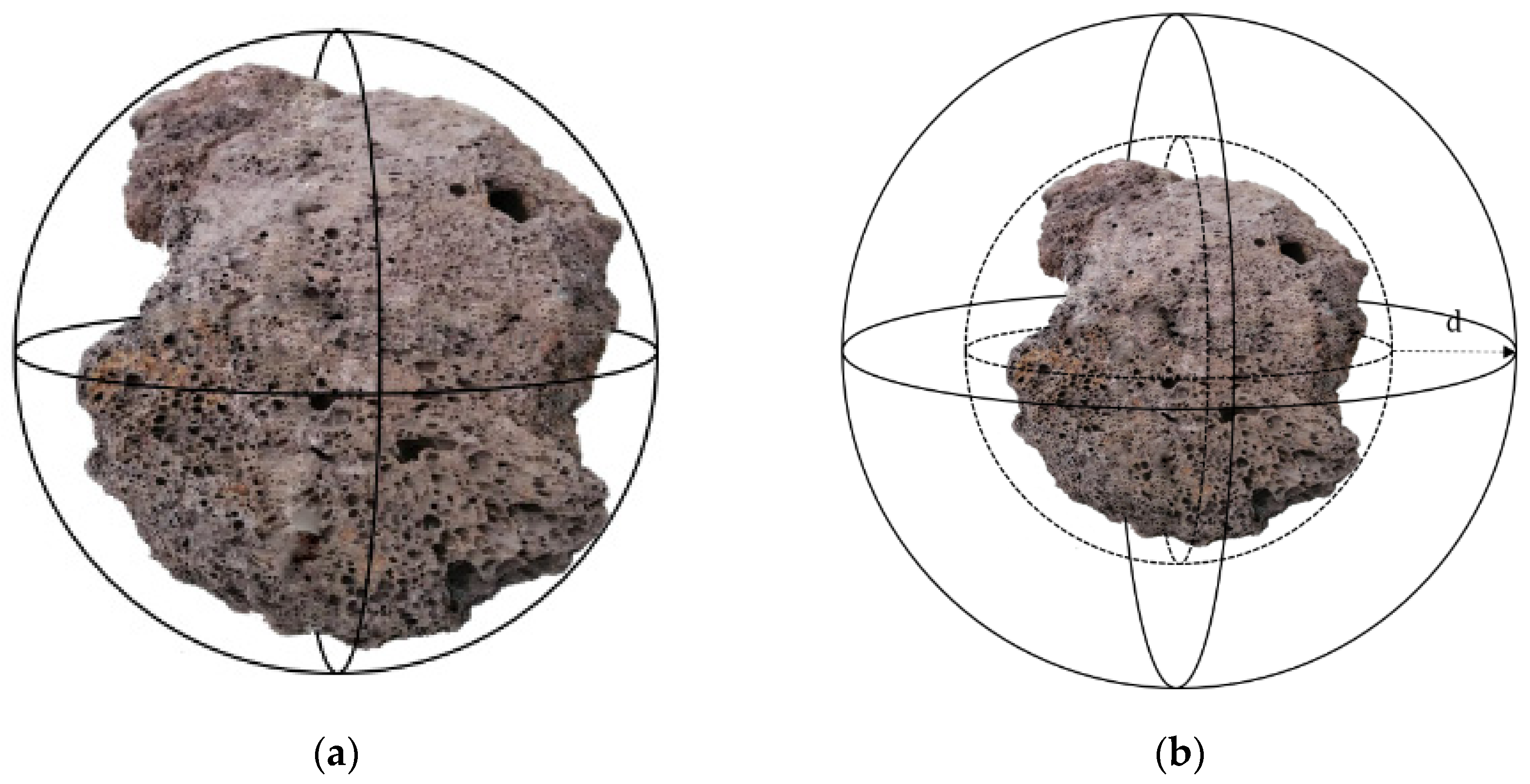
In three-dimensional environments, spherical models are widely used to construct obstacle models. Especially for irregular physical obstacles, they are often abstractly represented as specific spherical shapes. To retain the safety of path planning, these spheres are typically subjected to an inflation operation. Due to the fact that most obstacles have diversely irregular shapes in the actual environment, it is required to simplify them into sphere models and apply them to a path-planning algorithm. The inflation scale is often measured using a value of d. The specific value of d is adjusted based on the dimensions of AUV to ensure safe passage while minimizing the probability of collision between the AUV and the obstacle. A schematic illustration of the obstacle setting is shown in Figure 1.
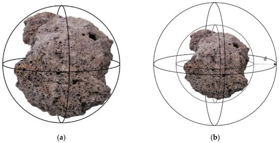
Figure 1.
Modeling of obstacle. (a) Obstacle spherification; (b) sphere inflation.
2.2. Experimental Preparation of Collaboration of Multiple AUVs
2.2.1. Setting of Multiple AUVs
Set represents the number of AUVs which perform n tasks, where notation represents the i-th AUV. For individual , the path from the starting point to the target point consists of a sequence of navigation waypoints. All waypoints between the starting point and the target point are connected, and then form the trajectory of the AUV. Here, set represents preset navigation waypoints between the starting and ending points of all AUVs, and represents the j-th waypoint of . Here, each waypoint contains three-dimensional coordinates .
2.2.2. Constraint of Multiple AUVs
The path length of the sailing distance between AUVs needs to be assigned according to the speed range of [, ]. According to spatial and temporal cooperative constraints, multiple AUVs’ cooperative constraints includes two aspects [28].
- (1)
- Spatial collaborative constraints
The spatial cooperative constraint guarantees collision avoidance between AUVs and ensures that the distance between AUVs is not less than the minimum safety distance.
In Equation (1), represents the distance between and and represents the minimum safety distance among all AUVs.
- (2)
- Temporal collaborative constraints
Temporal collaborative constraints ensure the synchronization of time for multiple AUVs to reach their ending points during a predefined time. We suppose a predefined time for the AUV to reach its ending point. The range for can be obtained using Equation (2).
where represents the path length of .
is able to complete the task within the specified time . Otherwise, the task cannot be completed on time, and the time cost needs to be considered in the fitness of the solutions [29]. The specific approach used for the calculation will be introduced in Section 3.2.
3. Methodological Design of AMP-PSO
3.1. Encoding of Particles and Population
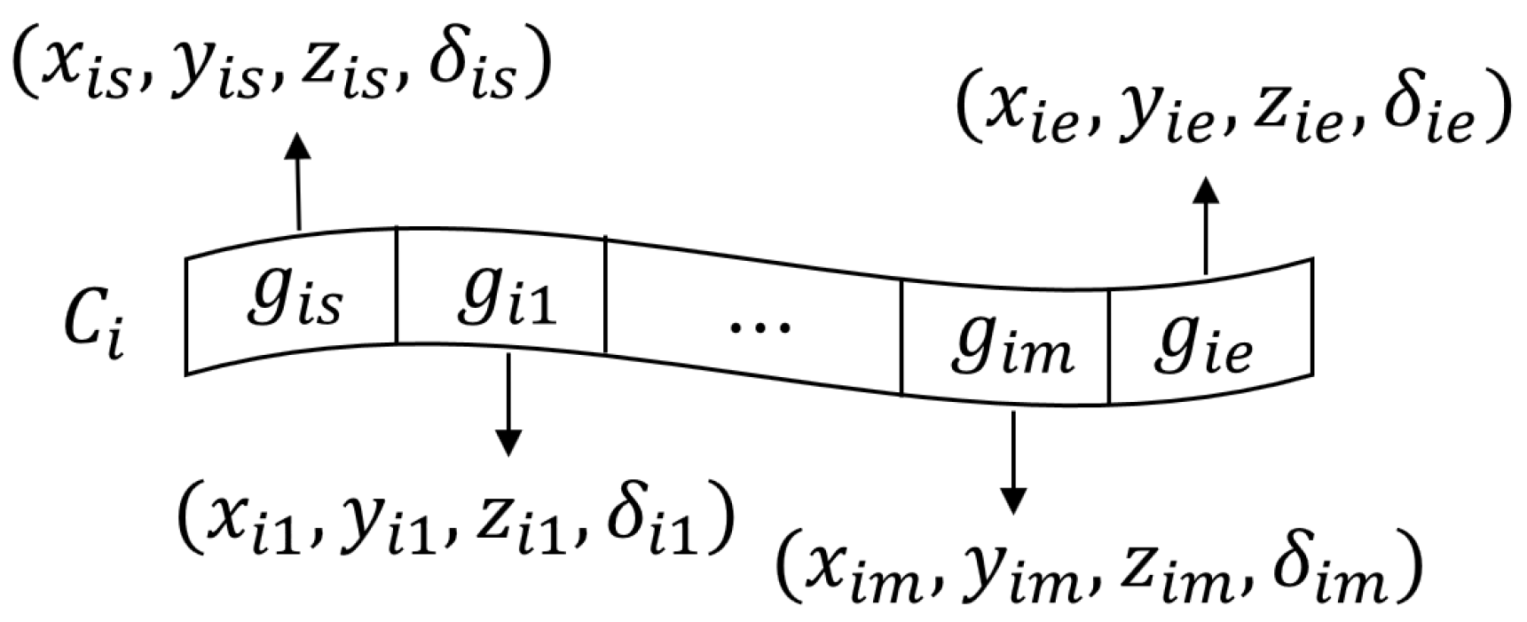
In cooperative path planning for multiple AUVs, an encoding chromosome is defined to represent single AUV trajectories. The size of each chromosome is determined by the number of predefined waypoints of the path length. For a single AUV , represents the starting point of the path, represents the end point of the path, and represents the j-th internal waypoint of AUV . Each gene not only contains coordinates of waypoint , but also includes the status information , which represents the information on the speed and direction of the AUV at the waypoint as shown in Equation (3)
In multi-AUV collaborative path planning, notations and denote the starting and ending points, and denotes the inner waypoint. The gene segment of chromosome contains coordinate information and status information, as shown in Figure 2.
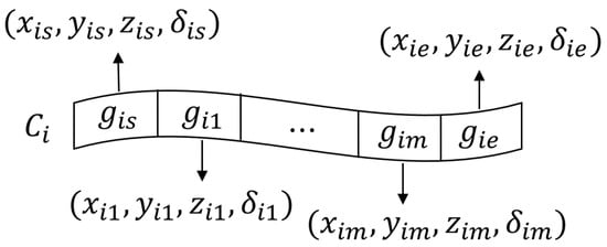
Figure 2.
Encoding of chromosomes for AUV trajectory.
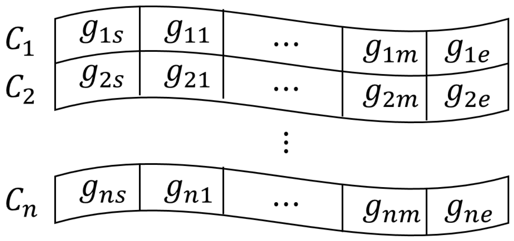
Based on the encoding chromosomes, each particle consists of multiple chromosomes, and each chromosome denotes individual AUV trajectories, as shown in Figure 3.
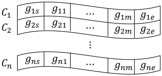
Figure 3.
Encoding of particle for multiple AUVs’ collaborative trajectories.
The diversity of the PSO population is one of the most crucial keys to prevent convergence in local optimization, which depends on the distribution of each particle in solution space. The uniform distribution function is used to generate random positions of initial particles. By adjusting the range and quantity of random generation, the particles can be effectively prevented from being clustered so as to enhance the diversity of the initial population. The random uniform distribution function is used to generate particle swarms such as , and population is denoted in Equation (4).
where is the particle as of Figure 2, and is denoted in Figure 1.
3.2. Design of Follower and Leader Populations in AMP-PSO
3.2.1. Initialization of Follower Populations
According to Equation (3), a group of follower populations are randomly generated, where denotes the follower population and denotes the total number of follower populations. As shown in Figure 4, the individual populations are quite different from each other so as to keep population diversity.

Figure 4.
Generation of follower population. Red, yellow, and purple spots respectively denote different particles in follower populations, and particles drawn with deeper color means high fitness.
3.2.2. Initialization and Updating of Leader Population
To achieve a better global solution under multi-objective conditions, we adopted a distributed strategy to retain and replace the best particles. We performed a selection process with the follower populations to identify particles with the best solutions and highest fitness.
- (1)
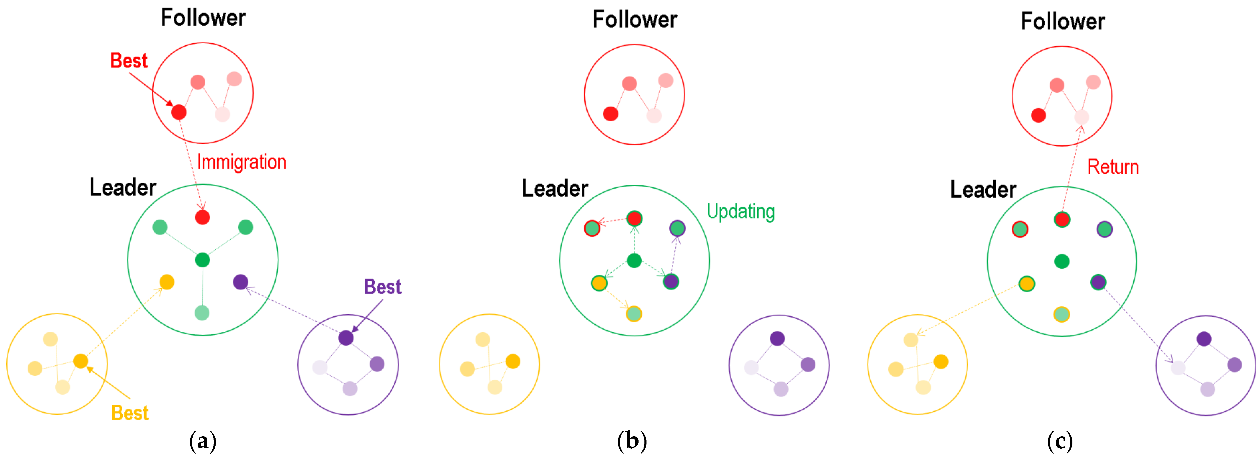
- As shown in Figure 5a, the best particles of each population were immigrated into a new population, which was considered as the leader population.
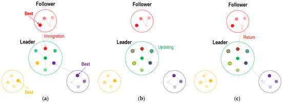 Figure 5. Initialization progress and updating rules of leader population. Green spots denote particles in leader population. (a) Particle immigration from follower; (b) particle updating in leader; (c) particle return to followers.
 - (2)
- As shown in Figure 5b, the immigrated particles and original particles were all updated in the leader population (the updating rules are introduced in Section 3.3.1).
- (3)
- As shown in Figure 5c, the immigrated particles returned to their own follower populations and replaced the worst one.
On the other hand, according to the process of Figure 5b, we achieved a renewal of the leader population, which allowed it to immigrate particles with higher fitness from the follower population. This distributed strategy ensured that excellent solutions could further the optimize leader population and provide a global solution. Furthermore, these immigrated particles from the optimized leader population were returned to different follower populations, promoting the fusion of global optimization and local priority. This strategy provides an effective approach for cooperative path planning and allows multiple AUVs to improve collaborative effects across multiple tasks.
3.3. Design of Updating Rules in AMP-PSO
3.3.1. Particle Updating in AMP-PSO
In classic PSO, each particle can be considered as a search individual in an n-dimensional space, where the current position of a particle represents a potential solution to the optimization problem. The particle’s velocity can be dynamically adjusted based on its own historical best position and the historical best position of the population. Particle updating possesses two attributes of the velocity vector and position vector , where and represent the velocity and position of the i-th particle at the j-th dimension, and n represents the total dimensions of solution chromosome. Particles search for the global optimal solution based on cost function, which is transformed into a penalty function to convert multi-constraint problems into unconstrained ones [30]. In each follower population, particles independently undergo adaptation based on their respective evolutionary strategies. In the iteration of follower population, particles update their velocity vector and position vector using Equation (5).
where is the inertia weight factor, and are acceleration factors, and and are uniformly distributed random numbers between 0 and 1. represents the historically optimal particle of generation k, and represents the globally optimal particle of generation k.
For the leader population, the particles not only optimize themselves based on their individual evolutionary particles, but also use the evolutionary particles of the follower populations to further improve their own performance. Therefore, the velocity and position are updated by Equation (6) as follows.
In Equation (5), represents the globally optimal particle in the follower population. stands for the acceleration factor, and is a uniformly distributed random number between 0 and 1. In the first formula of Equation (5), the first term of the summation represents the inertia (the particle keeps moving in the direction in which it had previously moved), the second term represents memory (the particle is attracted to the best point in its trajectory), the third term represents cooperation (the particle is attracted to the best point found by all particles of the leader population), and the last represents information exchange (the particle is attracted to the best point found by the follower populations).
3.3.2. Adaptive Parameters of AMP-PSO
In follower populations, the value of the inertia weight gradually decreases with the increase in iteration generations. This strategy facilitates the initial searching of particles for a large solution space, while it constrains the final searching of particles in a small solution space. The inertia weight significantly affects the convergence of the particle swarm algorithm. Its value is typically chosen within the range of 0 to 2. On the other hand, the parameter decreases as the iteration generations increase, thereby enhancing the particles’ local search capability. Meanwhile, the parameter increases with the increase in iteration generations to enhance the particles’ global search capability. The values of these three parameters, and are typically selected from the interval between 1 and 2 [31]. To achieve the adaptive adjustment of parameters, their values can be selected using the following Equation (7).
where represents the iteration generation and represents the maximum number of evolutions.
In the leader population, the parameter is similar to . Therefore, can be expressed as the following Equation (8).
By incorporating adaptive parameters, particles can explore the solution space more effectively and thoroughly, and reduce the need for manual parameter adjustment so as to improve the adaptability of AMP-PSO.
3.4. Fitness Definition
The cost function can be converted into a multi-objective optimization problem [32]. AUVs are typically equipped with batteries or other energy sources that have limited power. Path planning should minimize the energy consumption of the AUV during its missions without depleting its battery before returning to base or a charging station. Therefore, energy consumption can be used as a factor in the fitness function [33]. For a single AUV, the main factors affecting the AUV’s energy consumption are the length of the planned path, the depth of the AUV dive, and the influence of soft obstacles. Therefore, the fitness function can be expressed as Equation (9).
where , , and represent the path length fitness, depth fitness, and soft obstacle threat function, respectively. , and are weighted coefficients.
Compared with the single AUV evaluation function, the multiple AUVs’ cooperative evaluation function mainly integrates the cooperation of both temporal and spatial domains [34]. The time cost function of multiple AUVs can be expressed as Equation (10).
where represents the actual sailing time taken by to reach the target point.
To calculate the space cost, if the distance is less than the minimum safety distance , the space cost function of multiple AUVs can be expressed as Equation (11). The number of collisions is added to one for each point increase in space cost, and when the number of collisions is greater than or equal to ten, the AUV is damaged and cannot complete the mission.
where represents the distance between and .
Here, the fitness function of multiple AUVs can be expressed as Equation (12).
where represents the number of AUVs and are the weight values assigned to each fitness factor.
4. Numerical Experiments and Simulation Results
4.1. Setting of Computation and Experiment
4.1.1. Computational Environment
To validate the effectiveness of collaborative path planning for multiple AUVs, we used MATLAB2017B to execute AMP-PSO, MP-PSO, A-PSO, and A-PSO, combining Cuckoo Search (CS-PSO) and classic PSO for different simulations. The computer specs included Intel Xeon(R) E-2224G CPU with 3.50 GHz, 32G memory, and NVIDIA GeForce RTX 2080Ti as the computational platform.
4.1.2. Setting of Multiple AUVs Environment
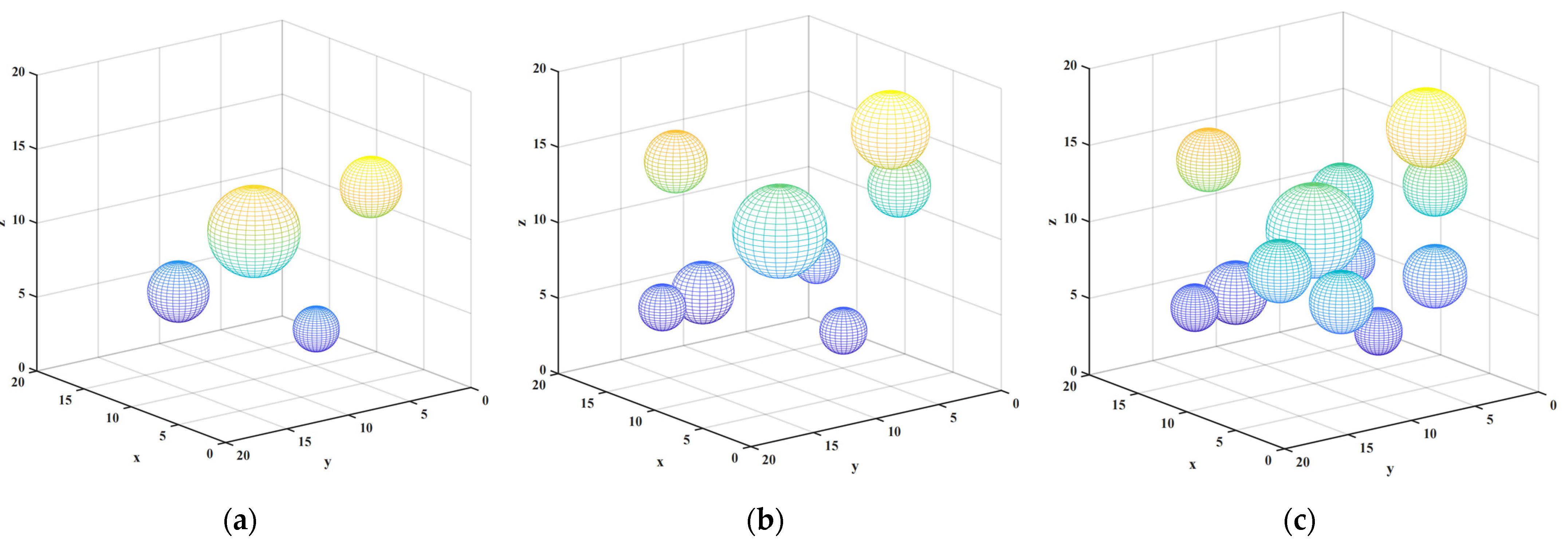
We set three scenarios involving collaborative path planning for multiple AUVs. We considered obstacles of varying quantities and radii, and set different starting and target points for AUVs to simulate diverse situations. The detailed information regarding the positions, sizes of obstacles, and the starting and target points of AUVs are given in Table 2 and Table 3. The specific layouts of these experimental scenarios are shown in Figure 6.

Table 2.
Parameter settings of obstacle environment.

Table 3.
Parameter settings of multiple AUVs.
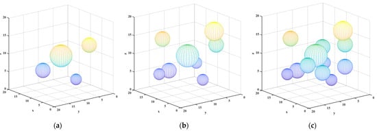
Figure 6.
Scenarios of experimental environment. (a) Scenario No. 1; (b) scenario No. 2; (c) scenario No. 3.
In scenario No. 1, we introduced HObs#1, SObs#1, and SObs#2. Both starting and ending positions were set for AUV#1 and AUV#2. In scenario No. 2, we increased HObs#2 and HObs#3, SObs#3 and SObs#4, and AUV#3. In scenario No. 3, we further increased Hobs#5, SObs#5 to SObs#7, and the new AUV#4 and AUV#5. Through these scenarios, we investigated how multiple AUVs cope with the challenges of complex obstacle layouts under different starting and ending points. According to these three distinct simulation environments, we comprehensively evaluated the performances of the proposed AMP-PSOs across various scenarios and provided a better understanding of their applicability and efficiency.
4.1.3. Setting of AUV Motion Environment
In the AUV motion environment, the navigation space for the AUVs was set to 2 × 2 × 2 (km)3. The speed of each AUV was set from 1 knot to 3 knots. Due to the varying complexity of the environment, it made sense to set the instruction times to 2100 s, 2300 s, and 2700 s. To ensure the safety of AUV navigation, a minimum safety distance of 0.05 km was set. The number of waypoints for each AUV was established at 30 points. In order to better simulate real underwater operating conditions, the movement of AUVs was subject to certain restrictions [35]. To keep the safety of AUV on the sailing path, we set the turning angle and the pitch angle for . Specifically, the turning angle of the AUV was limited to the range of [−35°, 35°], and the pitch angle was limited to the range of [−20°, 20°]. These restrictions ensured that the AUVs movement would remain within reasonable limits during actual operation. The details are shown in Table 4.

Table 4.
AUV motion parameters.
4.1.4. Setting of Algorithm Parameters
Cooperative path planning of multiple AUVs requires AUVs to avoid collisions and avoid obstacles. Therefore, in the cost model, the space cost and the threat cost received the highest weighting coefficients. Additionally, we wanted the AUV to travel as short a distance as possible. Therefore, the weighting coefficient for distance cost was higher than other costs. For this purpose, was set to (0.2, 0.1, 0.3, 0.1, 0.3) in this study.
It is generally required to have an appropriate number of particles to ensure that an algorithm is adequate for global search capabilities. However, this can also result in increased computational effort. It is important to strike a balance between global search effectiveness and computational efficiency when selecting the number of particles. Here, the number of particles was set within the range of tens to hundreds, which is a commonly chosen range. In this study, we chose 50 particles as the population size. At the same time, the number of particles in each population has a positive effect on improving the search range and finding the globally optimal solution more quickly, but also increases the running time of the algorithm. In general, a number of particles in the range of 20 to 40 within a population is a common choice, and particularly complex problems may require more. In this study, we chose 50 particles for the experiments.
In the comparison experiments, we set to 0.15 and both and to 1.5. The choice of these parameters was intended to ensure that the particles would be able to adequately explore the search space while finding a balance in terms of controlling the consumption of the algorithm runtime. To ensure that the algorithm would converge and complete the optimization process within a limited number of iterations, we set the number of iterations to 200. The detailed algorithm parameters of this study and the comparison with parameters of the contrast algorithms can be found in Table 5. By carefully selecting these parameters, our goal was to achieve efficiency and effectiveness of the algorithm and provide accurate and practical solutions to the problem of path planning of multiple AUVs.

Table 5.
Parameter settings of different PSO algorithms.
4.2. Experimental Comparison of Simulation Scenarios
In scenario No. 1, the number of obstacles was relatively small, and the environment was relatively simple. In Figure 7, it can be observed that all five algorithms successfully found collision-free paths. However, the algorithm proposed in this study demonstrated significant advantages in the AUV navigation process. It generated the shortest overall path, enabling the AUV to reach the target point faster and minimizing the associated costs.

Figure 7.
Results of scenario No. 1. Notation means no collision. (a) Program run time; (b) collision number; (c) fitness.
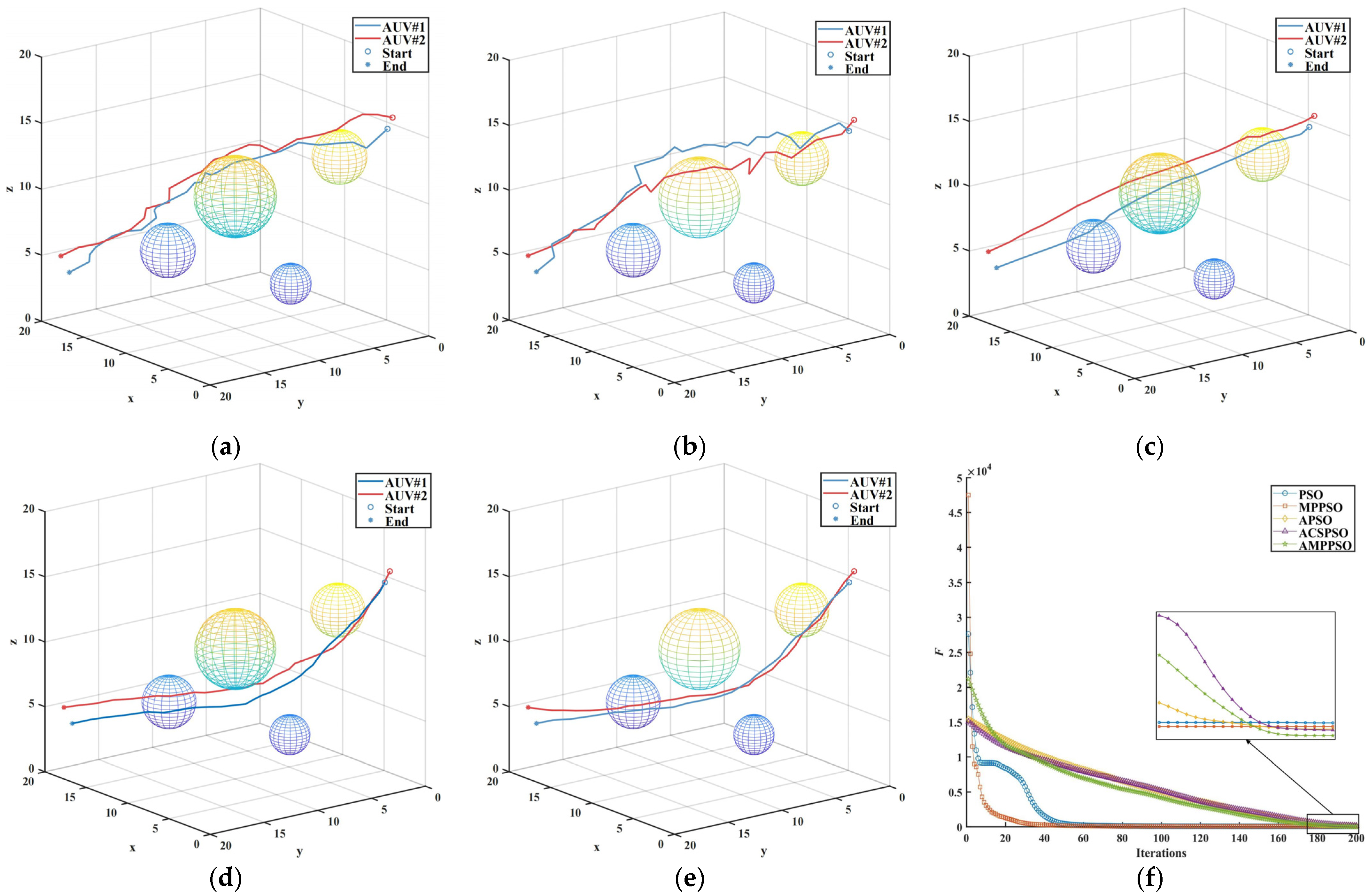
By observing Figure 8a–e, it is evident that the inclusion of the adaptive algorithm results in smoother paths that better align with the trajectory of the AUV. As can be seen from Figure 8f, the PSO algorithm and the MP-PSO algorithm quickly converge to the “optimal solution” and fall into the locally optimal solution, which was also one of the shortcomings of the original algorithm. In contrast, the A-PSO algorithm, CSA-PSO algorithm, and the algorithm proposed in this paper explored the space more fully. Although the convergence rate of the proposed algorithm was slow, it maintained the diversity of the particles so as to achieve a more comprehensive space exploration. After twenty iterations, the convergence speed of the proposed algorithm was accelerated, and a better convergence value of the objective function was achieved under the same number of iterations.
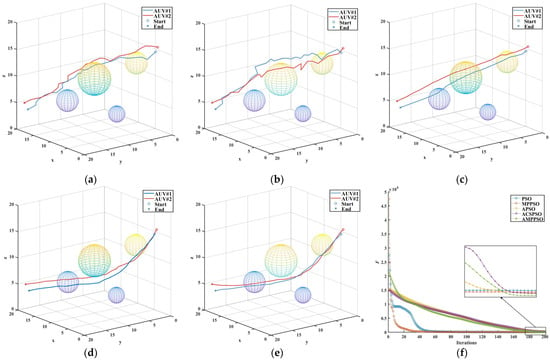
Figure 8.
Comparisons in scenario No .1. (a) PSO; (b) MP-PSO; (c) A-PSO; (d) ACS-PSO; (e) AMP-PSO; (f) fitness.
According to the above analysis, it can be concluded that in scenario No. 1, AMP-PSO, as proposed in this paper, showed excellent performance in terms of AUV path planning. It generated the shortest path to reach the target point quickly and completed the task with the lowest cost. In addition, the path generated by the algorithm was smoother and more consistent with the AUV’s track route. Although the convergence speed was slightly slower than other algorithms, the proposed algorithm was able to maintain a higher particle diversity and to achieve more adequate space exploration.
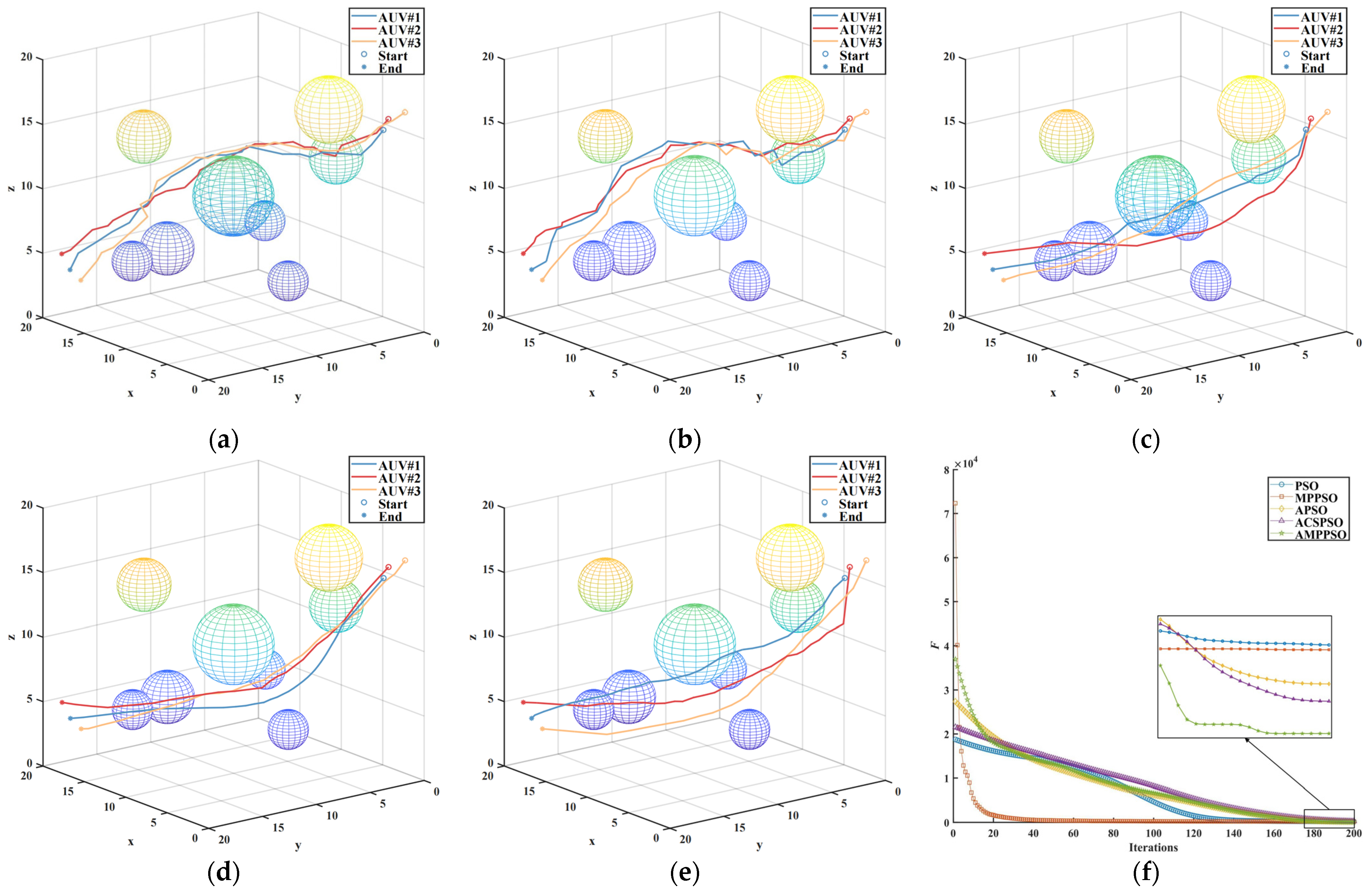
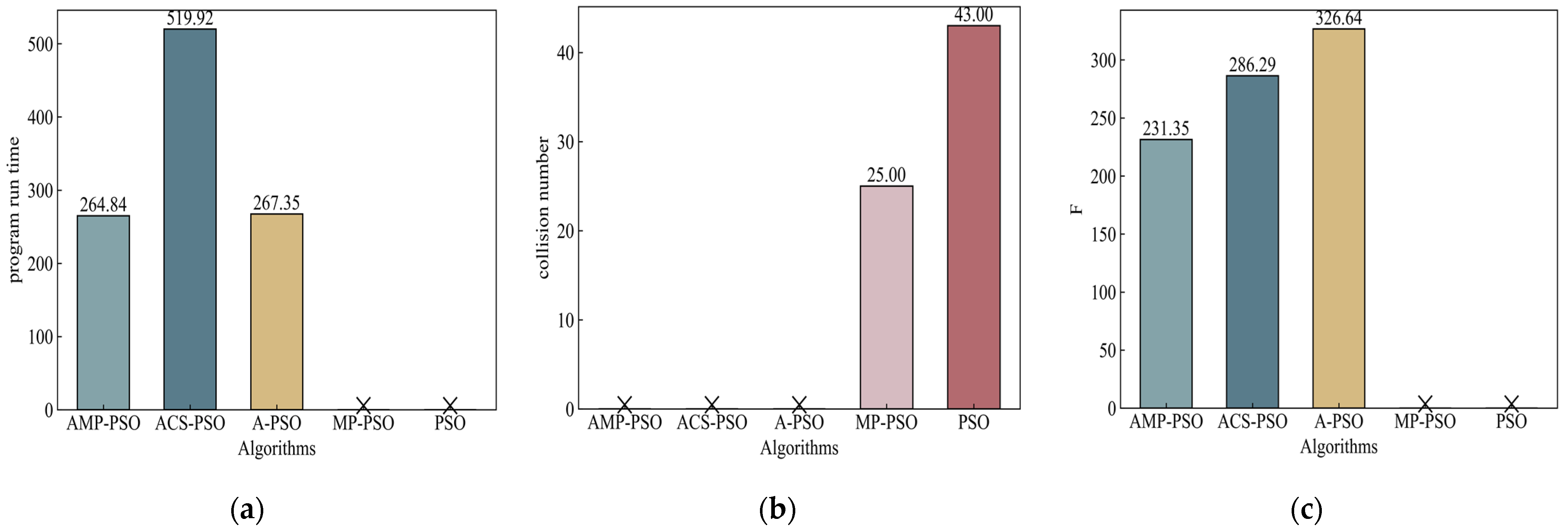
In scenario No. 2, the introduction of additional obstacles increased the complexity of the environment. In such a challenging setting, Figure 9 reveals that the conventional PSO algorithm failed to meet the requirements for the cooperative path planning of multiple AUVs. However, the other four algorithms still successfully found collision-free paths. Moreover, the computational efficiency of this paper’s algorithm was significantly higher than those of the other compared algorithms after boosting the complexity of the environment. Among these paths, the algorithm proposed in this study continues to exhibit its advantages.

Figure 9.
Results of scenario No. 2. Notation means no collision. (a) Program run time; (b) collision number; (c) fitness.
However, even in this more complex environment, the AMP-PSO proposed in this study maintained its superiority. Despite the increased obstacles, it successfully generated optimal paths for the AUVs, ensuring they would be able to navigate efficiently and reach their respective destinations without collisions. This underscores the robustness and adaptability of the proposed algorithm, which enable it to handle complex scenarios and outperform traditional PSO and other compared algorithms in the cooperative path planning tasks of multiple AUVs (see Figure 10).
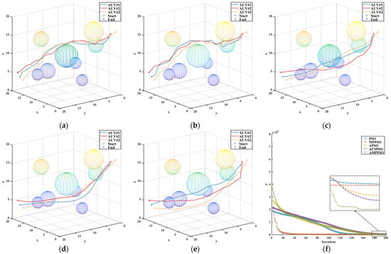
Figure 10.
Comparisons in scenario No. 2. (a) PSO; (b) MP-PSO; (c) A-PSO; (d) ACS-PSO; (e) AMP-PSO; (f) fitness.
In scenario No. 3, the environment became extremely complex, as is evident from the results presented in Figure 11. Neither the particle swarm optimization algorithm nor the MP-PSO algorithm were able to adapt to the challenging environment, and no way to avoid collision was found in the 200 generations. This shows their limitations in terms of dealing with increasing complexity and the numerous obstacles in the environment. However, the adaptive algorithm, designed to adapt to changing environmental conditions, proved its resilience by successfully planning high-quality paths despite the extreme complexity. This highlighted the capability of the adaptive algorithm to adjust its strategies and optimize path planning in response to the challenging environment.
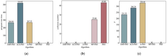
Figure 11.
Results of scenario No. 3. Notation means no solution in (a) and (c), and no collision in (b). (a) Program run time; (b) collision number; (c) fitness.
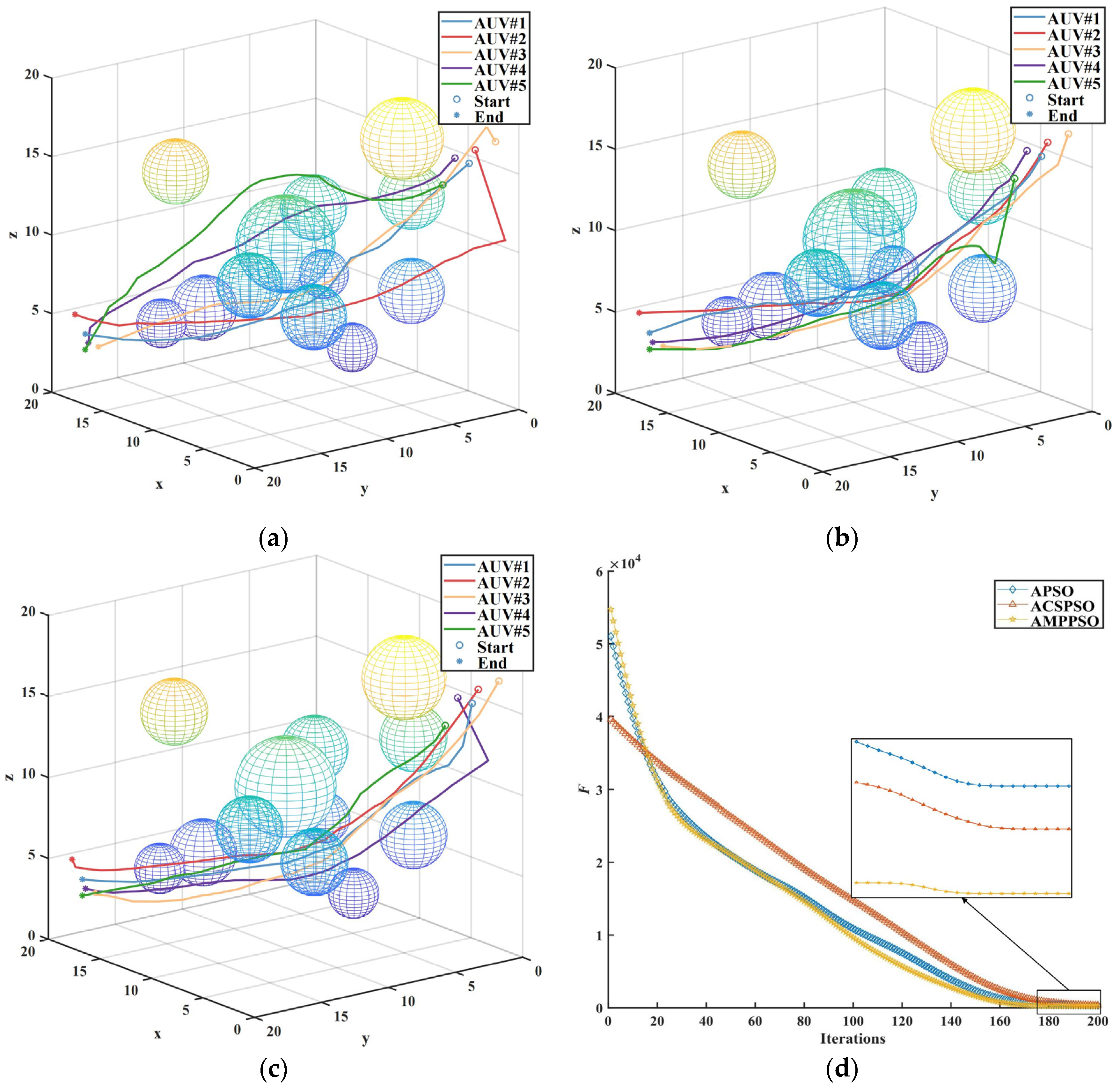
Moreover, the AMP-PSO proposed in this study continued to showcase its superiority, even in scenario No. 3. Despite the heightened complexity and numerous obstacles, it consistently generated excellent paths that allowed the AUVs to navigate effectively and reach their respective destinations without collisions. This further affirms the effectiveness and robustness of the proposed algorithm in terms of addressing the complexities of the cooperative path planning of multiple AUVs in highly complex environments (see Figure 12).
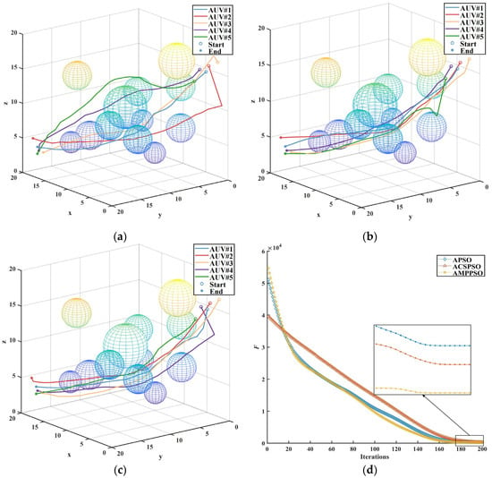
Figure 12.
Comparisons of scenario No. 3. (a) A-PSO; (b) ACS-PSO; (c) AMP-PSO; (d) fitness.
4.3. Discussion of Computing Time
Although our algorithm may have slightly longer runtimes in simple environments compared to other algorithms, it generates significantly higher fitness values. This is particularly evident in complex environments, where our algorithm not only outperforms other competing algorithms in terms of fitness, but also in runtime. This suggests that, although there is a trade-off between runtime and fitness, our algorithm has a clear ad-vantage in complex application scenarios that require high fitness. The computing times of our method and comparison methods are shown in Table 6. When considering real-time applications, it is important to ensure that the processing time falls within a specific range to facilitate timely decision making. Our method’s computational time fully meets the typical requirements for the real-time processing of underwater path planning. This efficiency is primarily due to the obstacle inflation processing and the strategy of treating multiple AUVs as moving obstacles relative to each other. The aim of obstacle inflation processing is to create safety buffer zones for AUVs, reducing the risk of collisions. This approach allows for the fine-tuning of obstacles without affecting the rest of the path planning. Our collaborative path-planning algorithm treats multiple AUVs as moving obstacles, enabling effective interaction and obstacle avoidance in dynamic environments.

Table 6.
Comparison of computing time of AMP-PSO and comparison methods.
5. Conclusions
To solve the problem of collaborative path planning of multiple AUVs, AMP-PSO was proposed in this paper. This paper first introduced the rapid development and wide application of AUVs, and emphasized the importance of multiple AUV systems in overcoming the energy and load capacity limitations of a single AUV. Then, the challenges and constraints of collaborative path planning with multiple AUVs were analyzed, and the existing AUV path planning techniques were reviewed. On this basis, the AMP-PSO algorithm was proposed, which uses a clustering strategy and adaptive parameter configuration to achieve a balance between global search and convergence speed. Through simulation evaluation, the performance of the algorithm was verified and compared with the traditional PSO algorithm. The results show that the proposed AMP-PSO algorithm can generate feasible and optimal path planning, so that multiple AUVs can effectively avoid obstacles and meet various constraints. Compared with traditional PSO algorithms, AMP-PSO has more advantages in terms of path quality and environment adaptability, and also achieved significant improvements in both procedure running time and path adaptation across all three scenarios. In Scenario I, AMP-PSO achieved a maximum improvement of approximately 126% in procedure running time and 80% in path adaptation. In Scenario II, AMP-PSO achieved a maximum improvement of approximately 92% in procedure running time and 96% in path adaptation. Finally, in Scenario III, AMP-PSO achieved a maximum improvement of approximately 96% in program running time and 41% in path adaptation. This research is of great significance for promoting the application of multiple AUVs in the fields of underwater exploration, monitoring, and reconnaissance, and provides an innovative solution to the collaborative path planning problem of multiple AUVs, with wide application prospects and practical value. However, there are several limitations of the current research, and we plan to improve them in future work. First, we plan to improve environmental modeling and simulations by including more shapes of obstacles (e.g., pipes) and moving obstacles with dynamic characteristics. Secondly, we plan to extend experimental comparisons including other classic evolutionary computation algorithms and deep reinforcement learning methods.
Author Contributions
L.Z.: formal analysis, methodology, validation, writing—original draft. Y.Z.: data curation, investigation, supervision, writing—review and editing. All authors have read and agreed to the published version of the manuscript.
Funding
This work was supported in part by the National Natural Science Foundation of China (grant nos. 52131101 and 51939001), and the Science and Technology Fund for Distinguished Young Scholars of Dalian (grant no. 2021RJ08).
Institutional Review Board Statement
Not applicable.
Informed Consent Statement
Not applicable.
Data Availability Statement
Data are contained within the article.
Acknowledgments
We acknowledge the BDAI lab at Dalian Maritime University for research and support.
Conflicts of Interest
The authors declare no conflicts of interest.
References
- Sahoo, A.; Dwivedy, S.K.; Robi, P.S. Advancements in the field of autonomous underwater vehicle. Ocean Eng. 2019, 181, 145–160. [Google Scholar] [CrossRef]
- Guo, X.; Chen, Y.; Zhao, D.; Luo, G. A static area coverage algorithm for heterogeneous AUV group based on biological competition mechanism. Front. Bioeng. Biotechnol. 2022, 10, 845161. [Google Scholar] [CrossRef] [PubMed]
- Hadi, B.; Khosravi, A.; Sarhadi, P. A review of the path planning and formation control for multiple autonomous underwater vehicles. J. Intell. Robot. Syst. 2021, 101, 67. [Google Scholar] [CrossRef]
- Li, H.; Wu, X.; Zhang, Z.; Tan, X.; Pan, Y.; Dai, C.; Luo, D.; Ahmed, A.; Xu, Y. An extended-range wave-powered autonomous underwater vehicle applied to underwater wireless sensor networks. iScience 2022, 25, 104738. [Google Scholar] [CrossRef] [PubMed]
- Cheng, C.; Sha, Q.; He, B.; Li, G. Path planning and obstacle avoidance for AUV: A review. Ocean Eng. 2021, 235, 109355. [Google Scholar] [CrossRef]
- Ahmed, F.; Xiang, X.; Jiang, C.; Xiang, G.; Yang, S. Survey on traditional and AI based estimation techniques for hydrodynamic coefficients of autonomous underwater vehicle. Ocean Eng. 2023, 268, 113300. [Google Scholar] [CrossRef]
- Chen, M.; Zhu, D. A workload balanced algorithm for task assignment and path planning of inhomogeneous autonomous underwater vehicle system. IEEE Trans. Cogn. Dev. Syst. 2018, 11, 483–493. [Google Scholar] [CrossRef]
- Li, J.; Xiang, X.; Dong, D.; Yang, S. Prescribed time observer based trajectory tracking control of autonomous underwater vehicle with tracking error constraints. Ocean Eng. 2023, 274, 114018. [Google Scholar] [CrossRef]
- Xiao, G.; Wang, B.; Deng, Z.; Fu, M.; Ling, Y. An acoustic communication time delays compensation approach for master–slave AUV cooperative navigation. IEEE Sens. J. 2016, 17, 504–513. [Google Scholar] [CrossRef]
- Cao, X.; Yu, A.L. Multi-AUV cooperative target search algorithm in 3-D underwater workspace. J. Navig. 2017, 70, 1293–1311. [Google Scholar] [CrossRef]
- Huang, H.; Zhu, D.; Ding, F. Dynamic task assignment and path planning for multi-AUV system in variable ocean current environment. J. Intell. Robot. Syst. 2014, 74, 999–1012. [Google Scholar] [CrossRef]
- Fang, Z.; Jiang, D.; Huang, J.; Cheng, C.; Sha, Q.; He, B.; Li, G. Autonomous underwater vehicle formation control and obstacle avoidance using multi-agent generative adversarial imitation learning. Ocean Eng. 2022, 262, 112182. [Google Scholar] [CrossRef]
- Blindheim, S.; Rokseth, B.; Johansen, T.A. Autonomous Machinery Management for Supervisory Risk Control Using Particle Swarm Optimization. J. Mar. Sci. Eng. 2023, 11, 327. [Google Scholar] [CrossRef]
- Lin, X.; Tian, W.; Zhang, W.; Zeng, J.; Zhang, C. The leaderless multi-AUV system fault-tolerant consensus strategy under heterogeneous communication topology. Ocean Eng. 2021, 237, 109594. [Google Scholar] [CrossRef]
- Zeng, Z.; Sammut, K.; Lian, L.; He, F.; Lammas, A.; Tang, Y. A comparison of optimization techniques for AUV path planning in environments with ocean currents. Robot. Auton. Syst. 2016, 82, 61–72. [Google Scholar] [CrossRef]
- Youakim, D.; Ridao, P. Motion planning survey for autonomous mobile manipulators underwater manipulator case study. Robot. Auton. Syst. 2018, 107, 20–44. [Google Scholar] [CrossRef]
- Saravanakumar, S.; Asokan, T. Multipoint potential field method for path planning of autonomous underwater vehicles in 3D space. Intell. Serv. Robot. 2013, 6, 211–224. [Google Scholar] [CrossRef]
- Hernández, J.D.; Vidal, E.; Moll, M.; Palomeras, N.; Carreras, M.; Kavraki, L.E. Online motion planning for unexplored underwater environments using autonomous underwater vehicles. J. Field. Robot. 2019, 36, 370–396. [Google Scholar] [CrossRef]
- Cai, W.; Zhang, M.; Zheng, Y.R. Task assignment and path planning for multiple autonomous underwater vehicles using 3D dubins curves. Sensors 2017, 17, 1607. [Google Scholar] [CrossRef] [PubMed]
- Hermand, E.; Nguyen, T.W.; Hosseinzadeh, M.; Garone, E. Constrained control of UAVs in geofencing applications. In Proceedings of the 2018 26th Mediterranean Conference on Control and Automation (MED), Zadar, Croatia, 19–22 June 2018. [Google Scholar]
- Ru, J.; Yu, S.; Wu, H.; Li, Y.; Wu, C.; Jia, Z.; Xu, H. A multi-AUV path planning system based on the omni-directional sensing ability. J. Mar. Sci. Eng. 2021, 9, 806. [Google Scholar] [CrossRef]
- Liu, C.; Lee, S.; Varnhagen, S.; Tseng, H.E. Path planning for autonomous vehicles using model predictive control. In Proceedings of the 2017 IEEE Intelligent Vehicles Symposium (IV), Los Angeles, CA, USA, 11–14 June 2017. [Google Scholar]
- Qian, C. Multiobjective evolutionary algorithms are still good: Maximizing monotone approximately submodular minus modular functions. Evol. Comput. 2021, 29, 463–490. [Google Scholar] [CrossRef]
- Liu, L.; Wang, X.; Yang, X.; Liu, H.; Li, J.; Wang, P. Path planning techniques for mobile robots: Review and prospect. Expert Syst. Appl. 2023, 227, 120254. [Google Scholar] [CrossRef]
- Panda, M.; Das, B.; Subudhi, B.; Pati, B.B. A comprehensive review of path planning algorithms for autonomous underwater vehicles. Int. J. Autom. Comput. 2020, 17, 321–352. [Google Scholar] [CrossRef]
- Sun, Y.; Gu, R.; Chen, X.; Sun, R.; Xin, L.; Bai, L. Efficient time-optimal path planning of AUV under the ocean currents based on graph and clustering strategy. Ocean Eng. 2022, 259, 111907. [Google Scholar] [CrossRef]
- Wang, L.; Liu, L.; Qi, J.; Peng, W. Improved quantum particle swarm optimization algorithm for offline path planning in AUVs. IEEE Access 2020, 8, 143397–143411. [Google Scholar] [CrossRef]
- Zhuo, W.; Longjie, J.; Hongmei, G.; Xiaoning, F. A path planning strategy for data acquisition task using multiple autonomous underwater vehicles. In Proceedings of the OCEANS 2016-Shanghai, Shanghai, China, 10–13 April 2016. [Google Scholar]
- Zhang, J.; Xiang, X.; Li, W.; Zhang, Q. Adaptive Neural Control of Flight-Style AUV for Subsea Cable Tracking Under Electromagnetic Localization Guidance. IEEE ASME Trans. Mech. 2023, 28, 2976–2987. [Google Scholar] [CrossRef]
- MahmoudZadeh, S.; Yazdani, A.M.; Sammut, K.; Powers, D.M. Online path planning for AUV rendezvous in dynamic cluttered undersea environment using evolutionary algorithms. Appl. Soft. Comput. 2018, 70, 929–945. [Google Scholar] [CrossRef]
- Li, G.; Chou, W. Path planning for mobile robot using self-adaptive learning particle swarm optimization. Sci. China Inform. Sci. 2018, 61, 052204. [Google Scholar] [CrossRef]
- Sui, F.; Tang, X.; Dong, Z.; Gan, X.; Luo, P.; Sun, J. ACO+ PSO+ A*: A bi-layer hybrid algorithm for multi-task path planning of an AUV. Comput. Ind. Eng. 2023, 175, 108905. [Google Scholar] [CrossRef]
- Qin, H.; Si, J.; Wang, N.; Gao, L. Fast fixed-time nonsingular terminal sliding-mode formation control for autonomous underwater vehicles based on a disturbance observer. Ocean Eng. 2023, 270, 113423. [Google Scholar] [CrossRef]
- Qin, H.; Chen, X.; Sun, Y. Adaptive state-constrained trajectory tracking control of unmanned surface vessel with actuator saturation based on RBFNN and tan-type barrier Lyapunov function. Ocean Eng. 2022, 253, 110966. [Google Scholar] [CrossRef]
- Liu, C.; Xiang, X.; Duan, Y.; Yang, L.; Yang, S. Improved path following for autonomous marine vehicles with low-cost heading/course sensors: Comparative experiments. Control Eng. Pract. 2024, 142, 105740. [Google Scholar] [CrossRef]
Disclaimer/Publisher’s Note: The statements, opinions and data contained in all publications are solely those of the individual author(s) and contributor(s) and not of MDPI and/or the editor(s). MDPI and/or the editor(s) disclaim responsibility for any injury to people or property resulting from any ideas, methods, instructions or products referred to in the content. |
© 2024 by the authors. Licensee MDPI, Basel, Switzerland. This article is an open access article distributed under the terms and conditions of the Creative Commons Attribution (CC BY) license (https://creativecommons.org/licenses/by/4.0/).

