Article

Load Assessment Method for Multi-Layer Oceanographic Winch with Synthetic Fibre Ropes Based on Non-Rotation Symmetric Cylindrical Model

1
Marine Engineering College, Dalian Maritime University, Dalian 116026, China
2
National Center for International Research of Subsea Engineering Technology and Equipment, Dalian Maritime University, Dalian 116026, China
3
Nantong Liwei Machinery Co., Ltd., Nantong 226522, China
4
CRRC SMD (Shanghai) Co., Ltd., Shanghai 201306, China
*
Author to whom correspondence should be addressed.
J. Mar. Sci. Eng. 2024, 12(3), 409; https://doi.org/10.3390/jmse12030409
Submission received: 26 January 2024 / Revised: 23 February 2024 / Accepted: 23 February 2024 / Published: 26 February 2024
(This article belongs to the Section Ocean Engineering)

Abstract

:
Offshore winches are crucial in marine engineering, particularly in marine scientific research and deep-sea exploration. The use of fibre ropes presents significant opportunities for the weight reduction of winches as a consequence of the low length–strength ratio and characteristics of corrosion resistance. Nonetheless, a challenge arises in underestimating the stress load levels in load assessments of multi-layer winch systems using synthetic fibre ropes. Traditional computational methods reliant on symmetrically rotational models fall short in accurately predicting and assessing practical applications. This paper introduces a finite element analysis model based on a non-rotationally symmetric approach with four surfaces subjected to various radial pressure on account of the deformation of the fibre ropes. In the design model, sixteen stress detection paths have been incorporated to identify and confirm non-linear stresses. The outcomes of the finite element simulations have been compared with experimental results with two synthetic fibre ropes, each with distinct deformation characteristics utilised. The findings demonstrate that the application of the model aligns well with experimental results, showcasing its relevance and practical value in real-world scenarios. Precise theoretical calculations and experimental validation are pivotal to ensuring that equipment reliability and safety are maintained alongside the pursuit of light-weighting.

1. Introduction

Oceanographic winches are crucial in marine engineering. Recent advancements have highlighted the significance of research winches that use synthetic fibre ropes, especially in challenging environments like polar regions and full ocean depths. The use of high module polyethylene (HMPE) ropes in the external structure of opto-electric and signal cables is vital in applications involving Remotely Operated Vehicle (ROV) winches and trace metal Conductivity, Temperature, and Depth (CTD) winches. Synthetic fibre ropes are 20–30% lighter than steel cables of equivalent diameter and strength [1,2,3]. This weight reduction offers multiple benefits, including longer rope lengths, increased payloads, reduced operating costs, and enhanced safety factors. Moreover, synthetic fibre ropes facilitate the use of smaller bending radius rope sheaves, more compact winch drums, and more potent power and braking systems, thereby yielding substantial economic advantages.
The design of winch structures is typically challenging, as it requires precise control over material usage, complicating the assurance of local strength. In the case of rope multi-layer winding, the winch structure endures a more complex set of loads compared to single-layer winding. The varying forces exerted on each layer make it challenging to accurately quantify the actual pressure exerted on the winch drum. Current methods for calculating loads in reel structure design involve estimating the average force across each force region throughout the operation. However, this approach fails to adequately account for dynamic and localised forces on the drum. Experimental evidence [4,5,6] indicates that the margin of error in empirical formula calculations is substantial, leading to significant discrepancies between calculated results and actual outcomes. Therefore, the design process of the reel must involve precise calculation of the actual stress values, accurate determination of the load spectrum under various operating conditions, and reasoned design of the drum.
The design methodology for winches is relatively traditional and suffers from a lack of clarity in design specifications [7,8,9,10]. This approach relies on numerous assumptions and simplifications, leading to low accuracy in calculations. Additionally, the safety technology parameters set during design are excessively high, resulting in increased material usage and elevated design costs. A pressing issue in contemporary design is the tendency towards excessive light-weighting, which significantly underestimates the structural strength requirements of the winch system in a multi-layer winding state. This oversight can lead to overdesign in terms of structural strength, thereby unnecessarily increasing the overall weight. Such an increase has ramifications, including higher maintenance and operational costs, elevated specifications for steel materials, and a greater environmental impact during the production process [11,12].
Multi-layer winding drums typically include smooth, helical, and double-grooved types. The double-grooved drum, noted for its ability to prevent tangling, enhances the smooth operation of the transmission. This design feature also reduces vibrations in the winching system, thereby increasing safety. As a result, the frequency and associated costs of rope replacement are reduced, which extends the operational lifespan. This extension, in turn, minimises downtime due to rope replacement, thus improving the operational continuity and efficiency of the equipment [13,14].
In mechanism, the primary external forces leading to the destruction of the drum are the radial pressure exerted by the rope on the drum surface and the axial thrust produced by the end side plate during the winding process. When deriving the drum force model, the cable, affected by the deformation of both the drum and the rope, is considered a fully flexible body, exhibiting longitudinal and transverse anisotropy. Additionally, the drum cylinder is assumed to be an ideal, rotationally symmetric body [4,15,16,17,18,19]. In 2004, Otto and Steffen introduced a novel computational approach [20] for analysing winch drums and flanges, treating them as a non-rotationally symmetric model. Consequently, the identification of a correlation between the stress difference and the asymmetric pressure loading on the rope sheath marked a significant advance in the theoretical analysis of winch drum strain characteristics, surpassing previous calculation methods. This study not only expanded the range of strain characteristics observed but also improved the accuracy of calculating the strain reference value.
The innovation presented in this paper is the application and validation of the non-rotation symmetric model initially proposed in theory. This model was analysed theoretically and then verified using finite element analysis software. The validation outcomes were compared with the results from two distinct experiments. The first was a full-scale experiment involving the winding of a 13,000 m long HMPE rope in a geological winch system [21]. The second involved a comparative analysis conducted on an experimental isometric design of a pulling experimental platform utilising a modified dimensionally stabilised HMPE rope [22]. The experimental results were assessed and corroborated using a strain detection device mounted on the surface of the drum. This device measured the nonlinear stress distribution on the winch drum, resulting from the synthetic fibre rope winding, at various positions and under various layers. The results confirmed the impact of the cable winding process on stress in critical parts of the winch during operation.
The paper is organised such that the second section details the derivation of principles and the evolution of radial pressure in the context of multi-layer winding winches calculations. This includes methods for load assessment on multi-layer winches, focusing on rotation symmetric load assumptions and radial pressures exerted by single and multiple layers of rope. Subsequently, this paper introduces a non-rotation symmetric model reflective of actual reel construction scenarios. This model not only facilitates load evaluation but also underpins the design used in finite element simulations. The third section presents experimental tests and finite element simulations, with their results and analyses forming the core of the fourth section. Finally, the fifth section provides a comprehensive summary of the methodology.

2. Methods and Models

2.1. Load Assessment Methods

To analyse the forces exerted on the rope wingding around the drum [23], the tension relationship is first illustrated, as depicted in Figure 1.
The figure depicts a section of the drum where the rope is subject to horizontal forces, as represented using the force equilibrium Equation (1):
( T + d T ) cos d α 2 = T 0 cos α 2 + μ d N
In this context, T represents the tension in the cable, while T 0 denotes the initial tension state of the rope before being subjected to external forces. The coefficient of friction, symbolised by μ , characterises the relationship between the frictional force and the normal support force N exerted by a section of the drum on the rope. Additionally, α is the angle illustrated in the micro-section of the drum and serves as the winding angle of the cable. This angle is instrumental in determining the variations in the mechanical characteristics of the rope at that specific position.
Figure 2 shows the force state of the rope in a multi-layer winding condition.
This concept also includes an equivalent relationship equation in the vertical direction, as depicted in Equation (2):
p i d A = p i 1 d A + ( 2 T i + d T i ) sin ( d α / 2 ) d α 0     d T i sin ( d α / 2 ) = 0 ( p i p i 1 ) d A = 2 T i sin ( d α / 2 ) d α 0     2 sin ( d α / 2 ) = d α ( p i p i 1 ) d A = T i d α
In the horizontal direction, the force relations are as outlined in Equation (3):
μ p i 1 d A = f i 1 μ p i d A = f i T i + f i = T i + d T i + f i 1 f i f i 1 = d T i   μ ( p i p i 1 ) d A = d T i
The relationship between the tensions at the rope ends, derived from the coupled Equations (1)–(3), is illustrated in Equation (4):
T = T 0 e μ α
Consider one layer of rope wound around the winch, as characterised by the relationship detailed in Equation (5):
p 1 d A = 2 T sin ( d α / 2 ) d A = D 1 d α 2 P p 1 D 1 d α 2 P = T d α     p 1 = 2 T D 1 P
The calculation of the radial pressure exerted by the rope wrapped around the winch forms the foundation for the current standard calculation methods. Concurrently, this method of calculating pressure is employed in finite element analysis to establish pressure boundary conditions for the rope on the winch drum. This aids in determining whether the winch’s structural strength can withstand all extreme conditions.
The analysis utilises the winch’s differential contact area, d A , which is then incorporated into the final results of Equation (2), leading to outcomes like those in Equation (6):
( p i p i 1 ) d A = T i d α d A = D 1 d α 2 P ( p i p i 1 ) D 1 d α 2 P = T 0 e μ α d α D i = D 1 ( i 1 ) P ( p i p i 1 ) = 2 T 0 e μ α D i P
Equation (7) is derived from Equation (6) in a condition of multi-layers:
p d r u m = 2 T 0 D 1 P i = 1 n 1 e 2 π μ c ( i 1 )
At this point, the ratio of the upper and lower layers is as shown in Equation (8):
R i R i + 1 = p i p i 1 p i + 1 p i = e 2 π μ c
During experimental procedures, strain gauges are commonly employed to measure strain, thereby facilitating the detection of stresses. In the winch system addressed in this paper, owing to its thin-walled structure, only tangential and axial stresses are considered. The equivalent stresses also referred to as von Mises stresses, are calculated using a specific formula to assess the winch drum’s strength. This particular calculation formula is presented in Equation (9):
σ θ = E 1 ν 2 ( ε θ + ν ε a ) σ a = E 1 ν 2 ( ε a + ν ε θ ) σ v = σ θ 2 + σ a 2 σ θ σ a

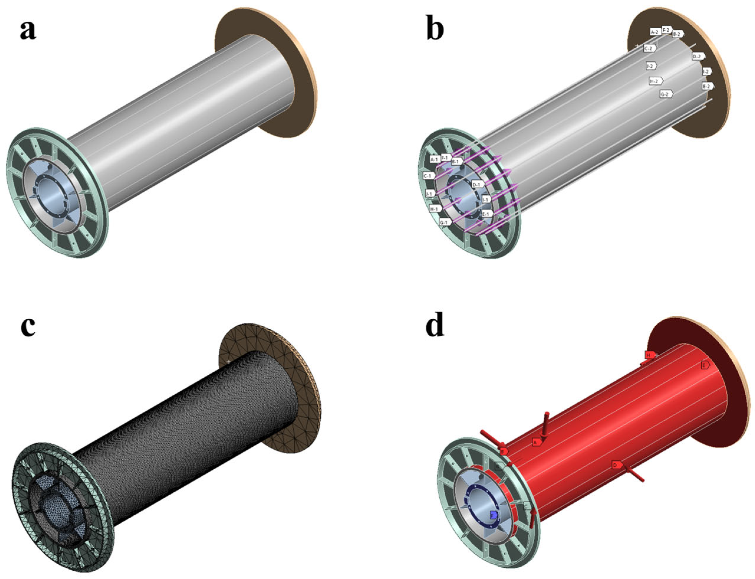
2.2. Non-Rotation Symmetric Model

In practical applications, to ensure the quality of synthetic fibre rope in the winch system during multi-layer winding, the LeBus design is often adopted [24,25,26,27], as illustrated in Figure 3. This winch drum design aims to effectively guide the rope in an orderly layer-by-layer arrangement on the drum and to maximise the prevention of winding issues such as cable gaps, jumping, and entanglement. In this design, the entire drum is typically divided into four sections upon deployment. The first section, known as the Parallel Area (PA1), is where the cable is initially guided into the winding process. In this area, the cable forms a pyramid-type arrangement, depicted in the upper part of Figure 3. The cable then enters the first Cross Area (CA1), where it is arranged in vertically stacked rows. As it travels between two adjacent zones, the rope shifts half a pitch in the axial direction of the drum. After passing through another parallel zone and cross-stacking region, the rope completes a full intercept shift in the axial direction, equating to one pitch position.
During the actual arrangement process of the rope, there is a variation in the height of the rope stacks. Figure 4 provides a specific schematic of this rope arrangement on the drum. In Figure 4a, the ideal rope stacking configuration is illustrated, where a gap of 0.15 times the rope diameter is typically maintained between the grooves to preclude deformation of the synthetic fibre rope from impacting the arrangement. Figure 4b depicts the deformation of the rope due to extrusion, often resulting in an ellipse shape. As per Equation (6), previously derived, changes in the winding diameter lead to alterations in the radial pressure exerted on the drum.
Equation (10) represents an advancement from Equation (6), illustrating the radial pressure beginning from the second layer in the parallel region. This is attributed to the change in winding diameter, whereby D2PA denotes the diameter of the first layer of rope winding plus twice the diameter of the short axis and an additional Δh. In the stacked region, due to the longitudinal and direct stacking arrangement, D2CA is calculated as the diameter of the first layer plus four times the radius of the short axis of the rope. The term κ introduced in this equation represents the ratio of radial pressure in the stacked region compared to that in the parallel region.
p P A = p a = p c = 2 T D 2 P A P = 2 T ( D 1 + 2 b + Δ h ) P p C A = p b = p d = 2 T D 2 C A P = 2 T ( D 1 + 4 b ) P p C A p P A = D 1 + 2 b + Δ h D 1 + 4 b = κ p C A = κ p P A
In the Non-Rotation Symmetric Cylindrical Model developed in this paper, the force analysis of the model’s structure is depicted in Figure 5. Regions A and C correspond to the parallel region shown in Figure 3, while regions B and D align with the rope crossing region in the same figure. The force relationship within this model is detailed in Equation (10). Due to the varying radial compressive forces present, the model is aptly named the Non-Rotation Symmetric Cylindrical Model.

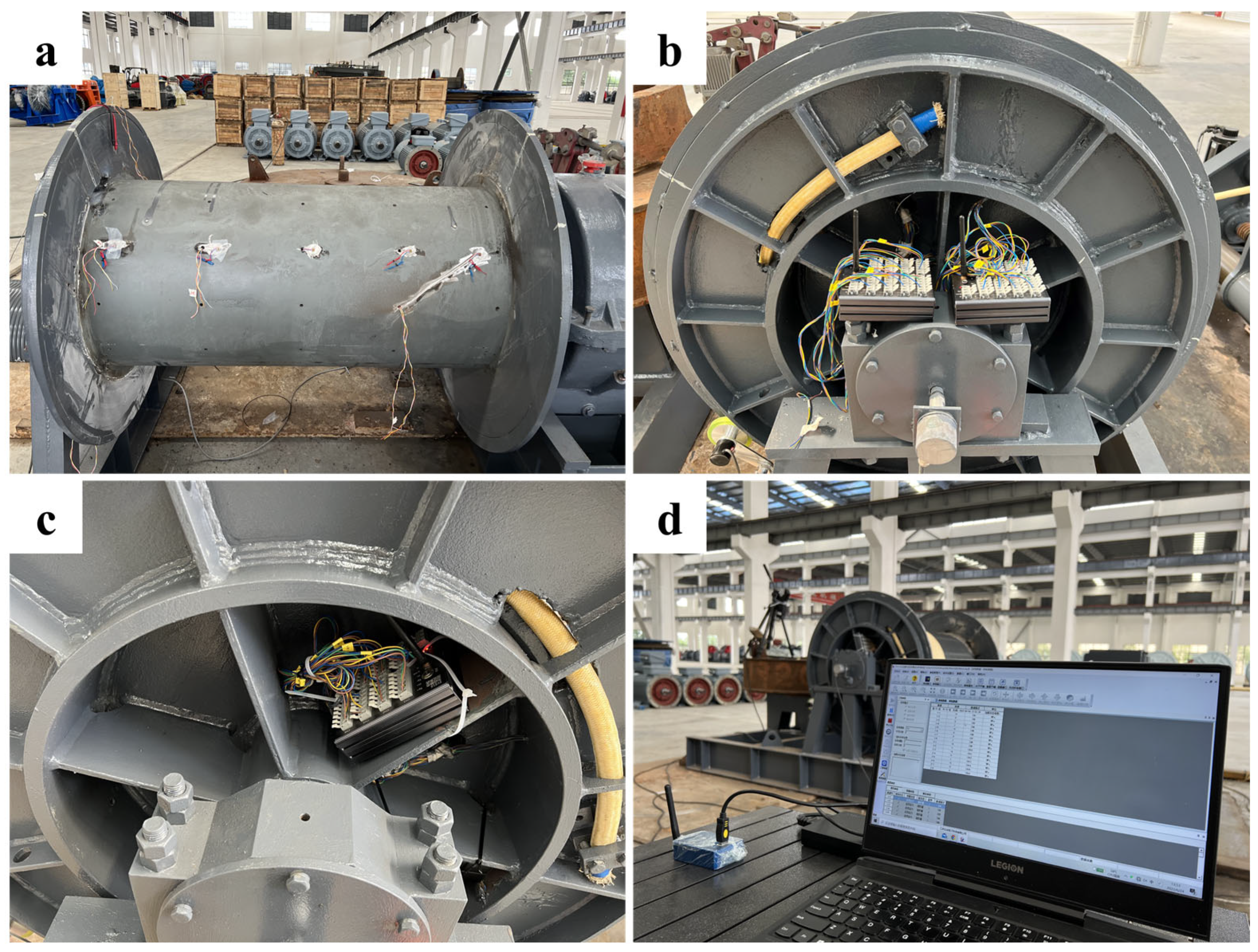
3. Experimental Work

3.1. Experimental Description

In the context of the studies discussed in this paper, our research team conducted two analogous experimental studies in 2020 and 2023. The first of these experiments, as illustrated in Figure 6a, featured a full-depth geological winch system comprising a typical combined winch setup, including both a traction winch and a rope storage winch. In contrast, the winch test system depicted in Figure 6b was specifically designed in a laboratory setting for assessing winch drum barrel stress. This setup included a test storage winch for experimentation and a pulling winch to generate the necessary pulling force. The two studies employed different cables: the first utilised a synthetic fibre cable without a lead core, as shown in Figure 7a, Rope A, while the second used a modified synthetic fibre cable with a lead core to evaluate cable deformation resistance, as seen in Rope B. Given that the outer diameter of the winch drums used in both experiments was 600 mm, and the nominal dimensions of the ropes were 24 mm, resulting in a D/d ratio of 25, the comparison between the two tests is scientifically valid. Notably, the lead core rope demonstrated an enhanced deformation resistance under the same winch working load.
The methodology for data acquisition during the experiment is depicted in Figure 8. Initially, strain gauges were affixed inside the winch drum barrel to monitor the strain changes of the winch throughout the rope winding process. The winch’s axial and tangential strains were measured using biaxial strain gauges, and due to the thin-walled nature of the structure, radial strain effects were disregarded. Figure 9a illustrates the biaxial strain gauges attached inside the winch, while Figure 9b displays the wiring process for the strain gauges. Figure 9c depicts the setup of the receiver for wireless signal transmission. The conversion of strain to stress is detailed in Equation (9).
In comparison to the prior method of slip ring testing, employing wireless test devices offers superior convenience and stability. Moreover, this testing approach facilitates the potential for long-term operational and maintenance testing of the winch’s stress state.

3.2. Finite Element Analysis Setup

The experiments described in this paper incorporate two rope configurations, with their respective composition diagrams illustrated in Figure 7 from the previous section. Figure 10 depicts the equivalent deformation model of the ropes. As noted in Figure 7, Model B [22], which includes a lead core inside, demonstrates enhanced resistance to deformation under force compared to Model A [21], which lacks a rope lead core inside. This model’s development stems from the derivation of a multi-layer winding and stacking model for the winding of synthetic fibre rope with multiple layers on the winch drum. Research work in 2023 [22] validates this derivation, and the measured equivalent deformation model is corroborated in real time using a laser profile scanner.
The setting of boundary conditions in the FEA software ANSYS Mechanical 2020R1 is depicted in Figure 11, where Figure 11a displays the established FEA model. The model’s construction principle, shown in Figure 5, sets four different regions, A, B, C, and D, to illustrate the non-rotation symmetry property. Figure 11b presents 16 paths added to the winch surface for linear result analysis of loads in the FEA. Figure 11c exhibits the meshing of the model, where after a sensitivity analysis, a 10 mm cubic mesh is employed for the detailed meshing of the winch’s reel, the primary focus of this study. Figure 11d illustrates the constraints and load conditions applied to the winch system during finite element analysis. The radial pressure on the winch drum surface and the axial thrust on the end side plate during winding are identified as the main external forces causing reel damage, as per the reel’s force analysis and rope winding mechanics. In the figure, pressures A, B, C, and D on the winch’s four surfaces are quantified in Equation (10). Constraint E is a cylindrical constraint at one end of the winch spool section, arresting radial rotation, while F is a fixed constraint on the other end of the winch model’s flange, allowing freedom only at the opposite end. G and H represent the end-side thrusts from cable stacking on the flanges, typically set at one-third of the radial pressure as per guidelines.
The reel material is Q345D steel, characterised by a modulus of elasticity of 206 GPa, a Poisson’s ratio of 0.28, and a density of 7.85 g/cm3.
In this study, three finite element simulation conditions are derived for the pressures exerted by points A, B, C, and D on the four faces of the winch model. These conditions are based on the variation in the height of the rope deformation mechanism, as illustrated in Figure 4, and the equivalent deformation model of the fibre rope obtained from experimental results shown in Figure 10. These conditions are further refined with the computational method outlined in Equation (10) to achieve a more accurate simulation. The height of an equilateral triangle with a base of 1.15 units and sides of 1 unit each is approximately 0.818 units. The corresponding angle is 70.2° according to Equation (10). The corresponding ratio κ of radial pressure in the stacked region to that in the parallel region calculated according to Equation (10) is 0.9930. Similarly, the corresponding coefficients of Models A and B for cable A and cable B are shown in Table 1.

4. Results

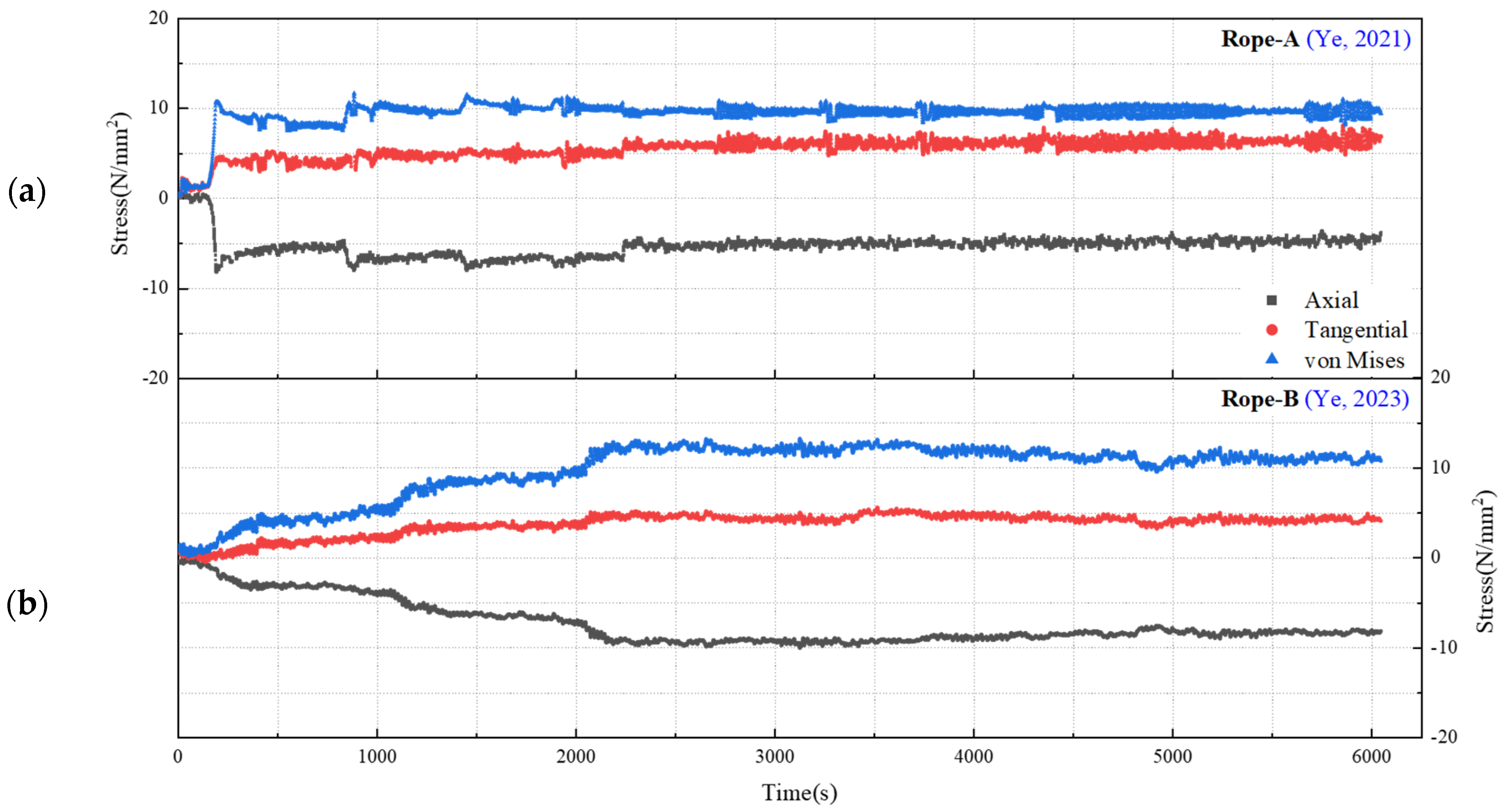
4.1. Experimental Results

The experimentally obtained cable stress data are depicted in Figure 12, presenting the stress measurements for ropes A and B wound on the winch and subjected to a traction force of 10 kN. In this study, we compared the effectiveness of various denoising techniques in processing stress data from winch drums [28,29,30,31]. The Gaussian filter, with its excellent smoothing capabilities and preservation of details, proved to be the most suitable denoising method for our data characteristics. By adjusting the standard deviation parameter, we optimised the filtering process, effectively reducing noise while retaining key features of the data. The experimental results showed that the data, after applying Gaussian filtering, exhibited significant improvements in both visual quality and statistical metrics. Compared to other methods, Gaussian filtering reduced noise by 70% while maintaining the integrity and accuracy of the data.
Figure 13 presents a schematic diagram of the maximum equivalent stress derived from analysing the results shown in Figure 12. The dimensionally stable rope B exhibits resistance to deformation as a consequence of a lead core inside that rope, as illustrated in Figure 7. In conjunction with Figure 12, it can be inferred that the dimensionally stable rope B with a modified structure exerts a greater stress impact on the winch drum barrel during winding compared to rope A. Furthermore, rope B demonstrates more stability than rope A, exhibiting less stress variation throughout the experimental process. The stress fluctuation range for rope B is also narrower than that of rope A. These two primary observations are primarily attributed to the differences in rope deformation.

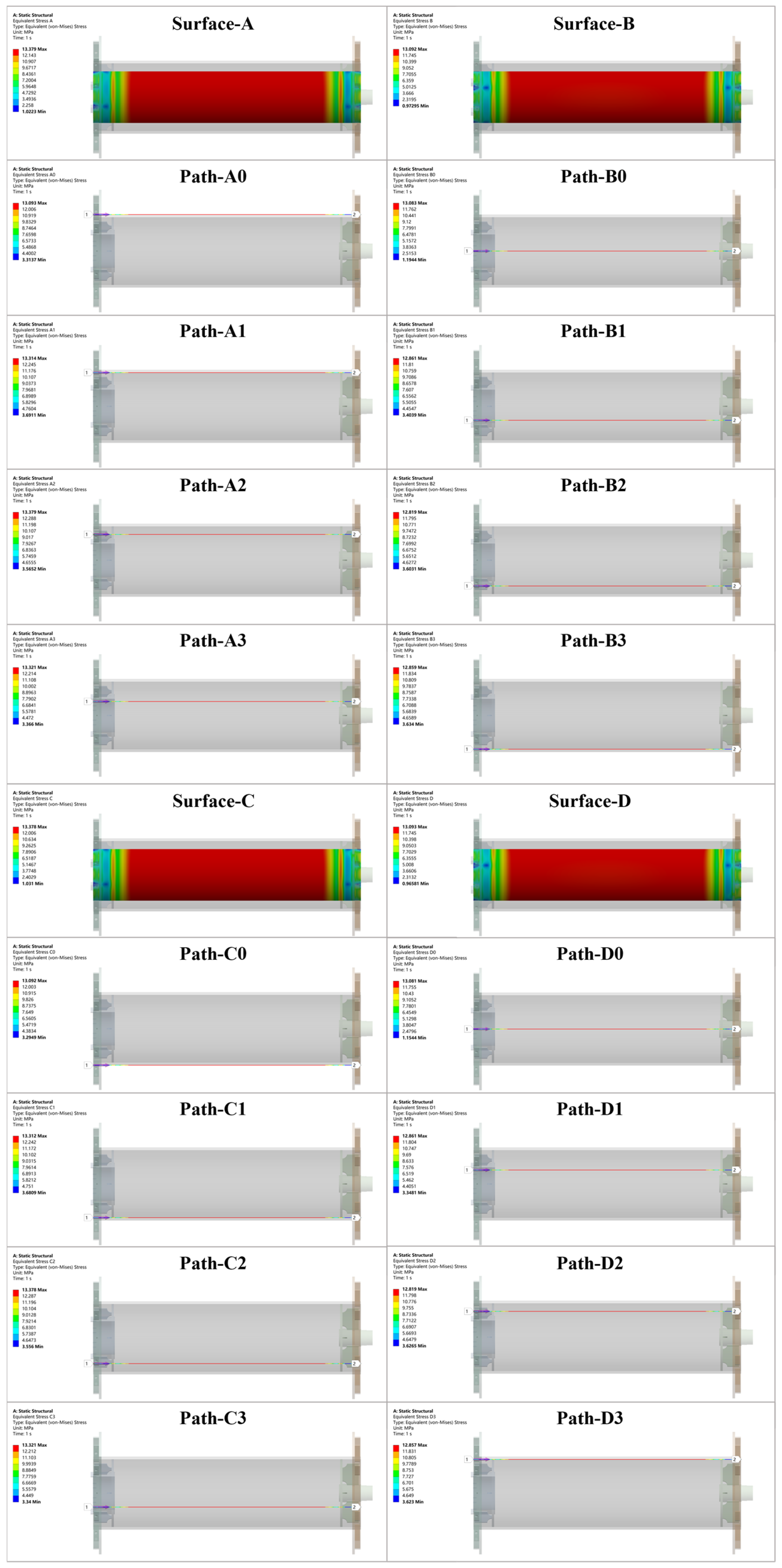
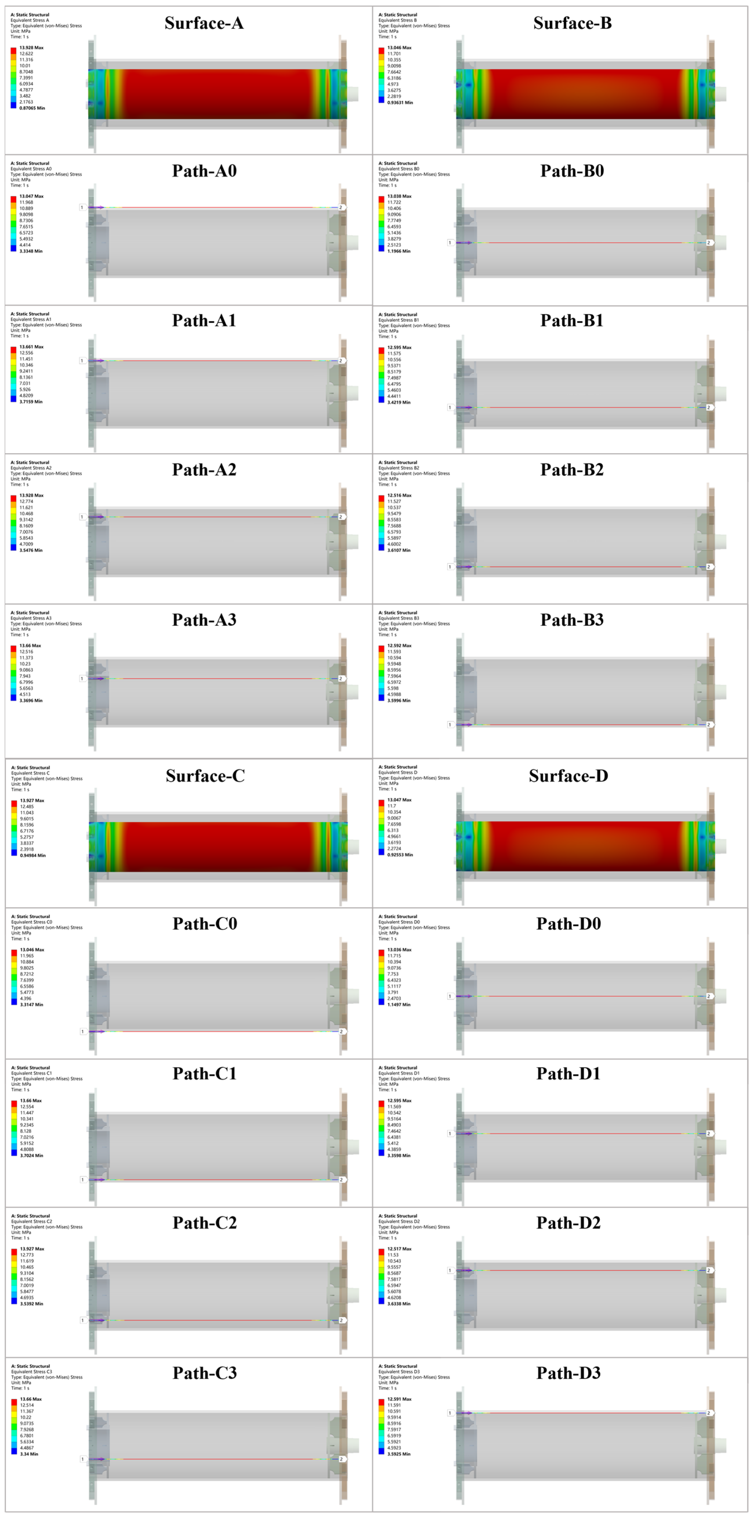
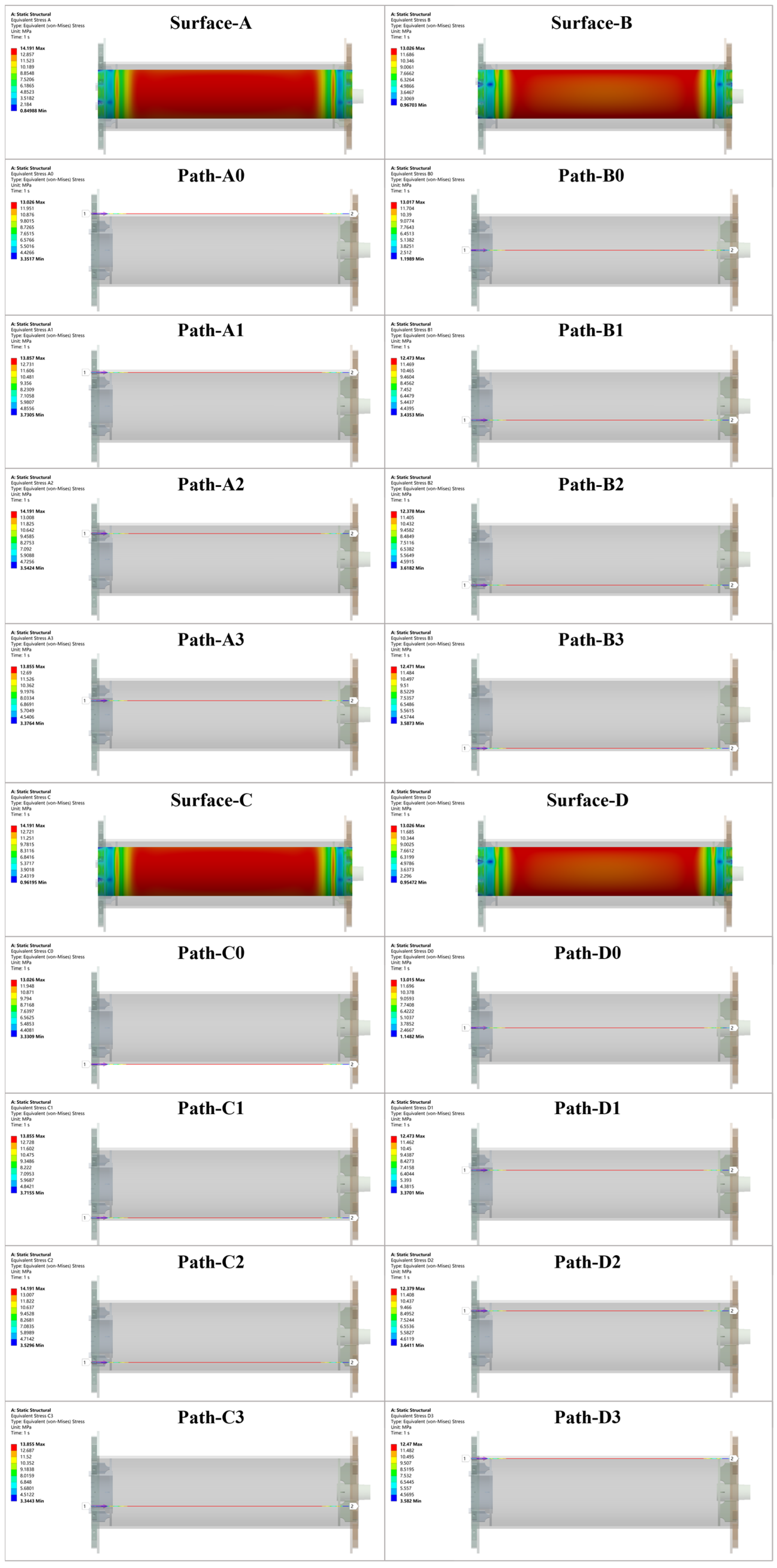
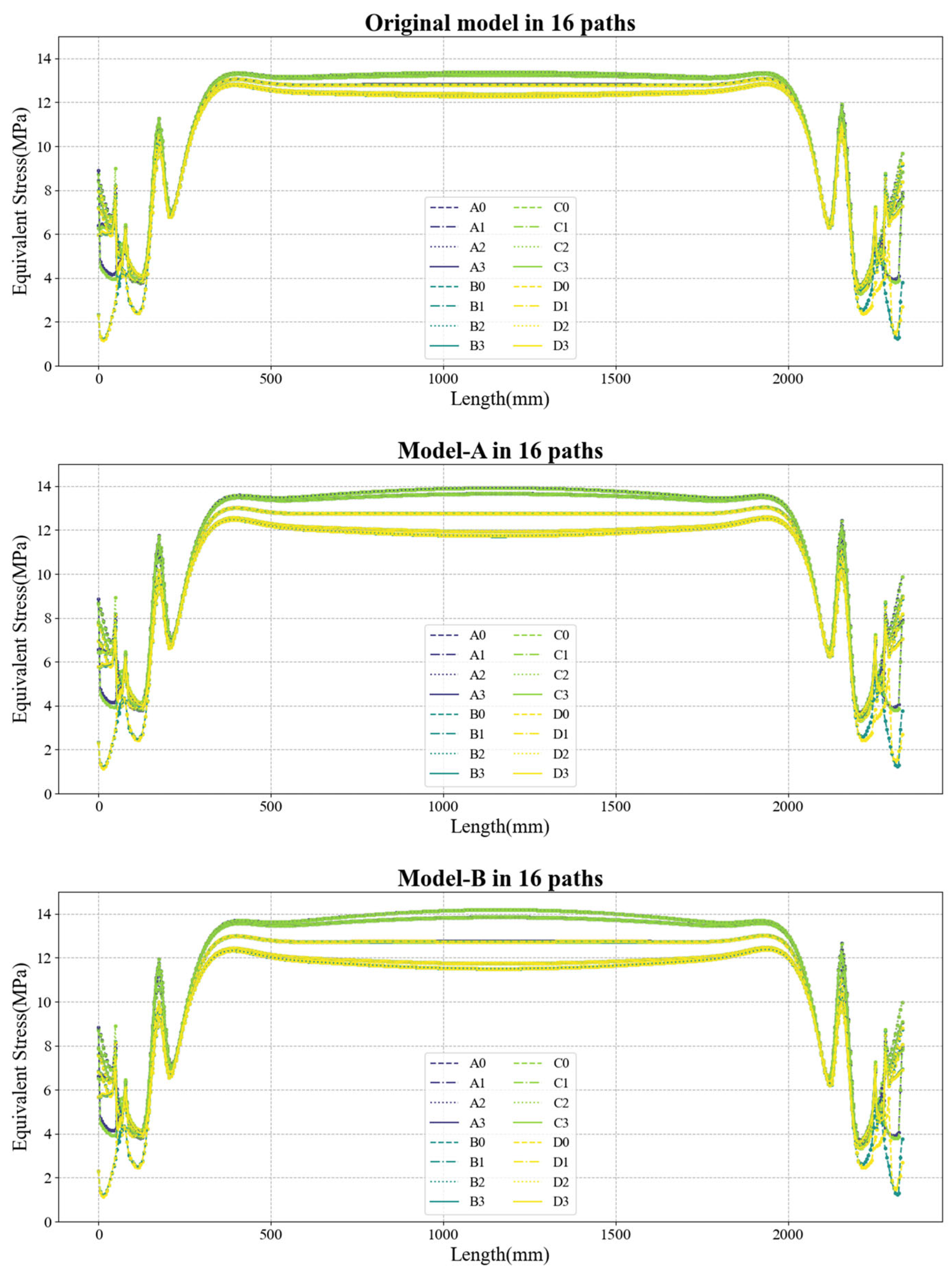
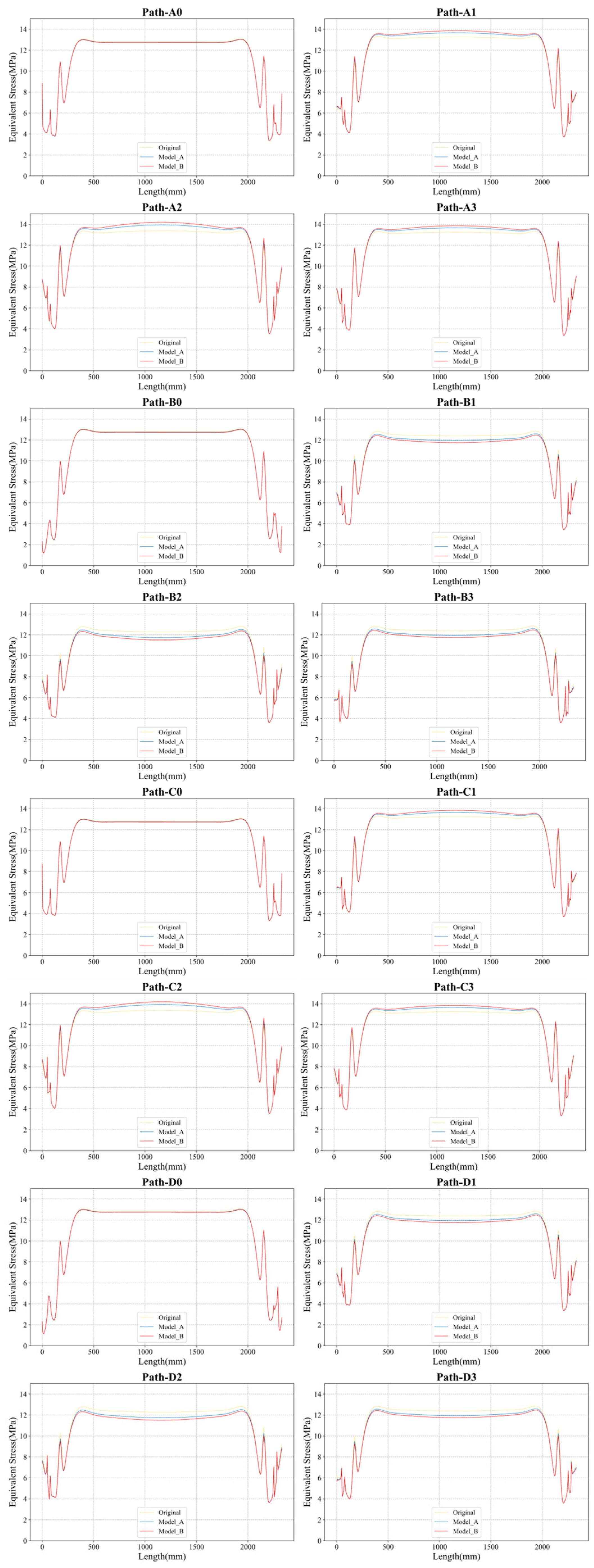
4.2. Simulation Analysis Results

Figure 14, Figure 15 and Figure 16 illustrate the FEA results for Model Original, Model A, and Model B, respectively. The analysis covers the four faces and 16 paths of each model. Detailed simulation results for these models are provided in Figure 17. Detailed stress relation curves for the three models, encompassing all 16 paths, are presented in Figure 18. Figure 19 presents a comparison between experimental data and simulation results. The average and median values of 16 sets of results from three simulation models are utilised for comparison with the experimental outcomes.
The finite element analysis results indicate that Model B experiences the highest stress, followed by Model A, with the undeformed original model exhibiting the lowest stress. In Model B’s calculations, the stress magnitude is approximately 14 MPa, while Model A’s stress is close to this, at around 13 MPa. In contrast, the Model Original’s stresses are the lowest according to the calculations. These simulation results align with the experimental data trend. However, there is a noticeable deviation between the numerical results of Model A in the finite element simulation and those obtained experimentally [21,22]. This discrepancy underscores the inherent asymmetry of the rotational model and suggests that treating the reel drum as an ideal rotationally symmetric body, as per traditional methods, is not sufficiently accurate when applying loads.
Additionally, simulation results across different paths reveal that maximum stresses typically occur at the centre of the winch drum barrel. At this central position, the highest stress is usually found in the parallel zone, corroborated by theoretical analysis indicating higher radial stress here than in the stacked cross-region. This theory is further validated in the finite element simulation analysis. At the boundaries where the regions transition, Model B’s stresses are generally calculated to be higher than those of Model A, and both are higher than the undeformed original model. A notable observation is that at the boundary contact paths connecting different regions (e.g., A0, B0, C0, and D0), stress differences are not as pronounced as in other locations. However, if the value of κ (the radial pressure difference in the non-rotation symmetric model) is reduced, a significant stress difference becomes evident. This difference is due to the pressure disparity, creating an axial displacement variation between parallel and intersecting parts, which in turn generates additional axial forces in the joint region. These forces must be considered in the design of the joint geometry or connections, such as welds or screws.
Moreover, due to the asymmetric loading, the stresses on the end side flanges are also significantly influenced. Finite element (FE) calculations reveal that the side discs experience uneven deformation, potentially leading to failures due to deflections and stress peaks at the junction with the jacket.
Table 2 presents the error analysis between the average values of two sets of experimental data and simulation results. It includes four primary error metrics: Mean Absolute Error (MAE), Mean Relative Error (MRE), Mean Squared Error (MSE), and Root Mean Squared Error (RMSE).
The MAE for the first set of data from Model A is 0.56429, while the MAE for the second set from Model B is 0.920445. MAE measures the average absolute difference between predicted values and actual values, indicating that the second set has a higher MAE and, thus, a larger average error than the first set, pointing to a lower prediction accuracy for the second set. MRE evaluates the absolute error in the context of the actual values, represented as a percentage. The MRE for the first set of data is approximately 4.65%, and for the second set, it is about 7.49%. This indicates that the errors of the second set are proportionally larger relative to their actual values, reflecting an increase in the relative inaccuracy of the predictions for the second set. MSE measures the average of the squared differences between predicted values and actual values, with a higher MSE indicating larger errors. The MSE of the second set is significantly higher than that of the first set, indicating that the predictions for the second set deviate further from the actual values on average. The RMSE for the first set of data is 0.628586, and for the second set, it is 1.014293. RMSE, being the square root of MSE, measures errors in the same units as the original data, making it easier to interpret.
By comparing these error metrics, it is evident that the second set of data from Model B exhibits a noticeable decline in accuracy compared to the first set from Model A. As observed in Figure 19, this may be due to the greater variability in the second set of data itself. However, considering the problem studied in this paper is the multi-layer winding of synthetic fibre ropes on winch drums, the magnitude of stress is greatly related to the number of layers and the characteristics of the rope itself. Therefore, in terms of the accuracy of the numerical prediction range, the comparison of experimental data to simulation results indicates that the data represented by Model B, as shown in the red part of Figure 19, is superior in accuracy to the data from Model A depicted in the blue part of the figure.

5. Discussion

In this paper, a method for load assessment for multi-layer oceanographic winches with synthetic fibre ropes based on Non-Rotation Symmetric Cylindrical Model was proposed. This feasibility of the model is first validated through theoretical derivations during the simulation process. Subsequently, it is further corroborated by comparing simulation outcomes with actual experimental results on strain stresses. Ultimately, by integrating the deformation of the model and considering its deformation patterns, we comprehensively analyse the winch drum’s stress state under various deformation scenarios. This approach enables us to discern the relationship between abrupt stress changes and cable deformation. Such a method is of significant relevance for the Load Assessment of Multi-layer Oceanographic Winches using synthetic fibre ropes, offering insights into their operational states.
In the experimental results, a discrepancy in the bending radius is observed at the notched sections. This variation in the radius of rope stacking layers inversely affects the internal radial pressure of the rope within each layer. At that time, theoretical calculations interpreted this phenomenon as resulting from an increased winding radius, where the winding pressure is lower in the cross-section than in the parallel section.
The finite element analysis simulations also reveal that significant deformation leads to a marked difference in stress. This variance is attributed to dissimilar radial pressures. Consequently, in the design process, the unique characteristics of the reel structure, coupled with the deformation attributes of synthetic fibre cables, result in considerable changes in radial pressure across the four areas of the outer jacket of the winch drum barrel. Such changes also affect the surface stress of the drum. This phenomenon can profoundly impact the reel’s structural integrity. Neglecting this aspect, especially in the pursuit of excessive lightweight, puts the stress assessment of the multi-layer winch drum at risk.

6. Conclusions

In conclusion, the stress calculation and experimental methods for synthetic fibre rope multi-layer winding winches based on the Non-Rotation Symmetric Cylindrical Model are essential in achieving winch weight and size reduction without compromising their strength. Precise theoretical calculations and experimental validation are pivotal to ensuring that equipment reliability and safety are maintained alongside the pursuit of lightweight.

Author Contributions

Conceptualization, H.Y., W.L. and S.L.; Methodology, H.Y. and W.L.; Software, H.Y.; Validation, H.Y., W.L. and S.L.; Formal analysis, H.Y.; Investigation, H.Y. and Q.L.; Resources, W.L. and Q.L.; Data curation, H.Y. and S.L.; Writing—original draft preparation, H.Y.; writing—review and editing, H.Y. and W.L.; Visualization, H.Y. and S.L.; Supervision, W.L. and D.Z.; Project administration, W.L., S.L., Q.L. and D.Z.; Funding acquisition, W.L., S.L. and D.Z. All authors have read and agreed to the published version of the manuscript.

Funding

This research was funded by the National Key Research and Development Program of China (2023YFC2809603, 2023YFC2809601, 2022YFC2806902), the Central Guidance on Local Science and Technology Development Fund of Liaoning Province (2023JH6/100100049), Liaoning Revitalization Talents Program (XLYC2007092), 111 Project (B18009) and the Fundamental Research Funds for the Central Universities (3132023510).

Institutional Review Board Statement

Not applicable.

Informed Consent Statement

Not applicable.

Data Availability Statement

The data presented in this study are available on request from the corresponding author. The data are not publicly available due to privacy and confidentiality considerations.

Conflicts of Interest

Author Qingtao Lv was employed by the company Nantong Liwei Machinery Co., Ltd. and author Dinghua Zhang was employed by the company CRRC SMD (Shanghai) Co., Ltd. The remaining authors declare that the research was conducted in the absence of any commercial or financial relationships that could be construed as a potential conflict of interest.

References

  1. Davies, P.; Reaud, Y.; Dussud, L.; Woerther, P. Mechanical behaviour of HMPE and aramid fibre ropes for deep sea handling operations. Ocean Eng. 2011, 38, 2208–2214. [Google Scholar] [CrossRef]
  2. Li, H.; Diaz, H.; Soares, C.G. A developed failure mode and effect analysis for floating offshore wind turbine support structures. Renew. Energy 2021, 164, 133–145. [Google Scholar] [CrossRef]
  3. Lin, S.; Li, G.; Li, W.; Ye, H.; Li, H.; Pan, R.; Sun, Y. Experimental measurement for dynamic tension fatigue characteristics of HMPE fibre ropes. Appl. Ocean Res. 2022, 119, 103021. [Google Scholar] [CrossRef]
  4. Lohrengel, A.; Stahr, K.; Schulze, M.; Wächter, M. Innovative drum construction for multi-layer winding with fibre ropes. In Proceedings of the OIPEEC Conference, Stuttgart, Germany, 24–26 March 2015; pp. 24–26. [Google Scholar]
  5. Skarbøvik, R.A.; Piehl, H.; Æsøy, V. Tangential stress in multilayer winch drums with high performance synthetic fibre ropes–analytical calculations versus experimental measurements. Ships Offshore Struct. 2020, 15, S82–S97. [Google Scholar] [CrossRef]
  6. Skarbøvik, R.A.; Piehl, H.; Torben, S.; Nedreberg, M.L.; Æsøy, V. Experimental investigation of stresses in winch drums subjected to multilayer spooling loads from synthetic fibre ropes. In Proceedings of the ASME 2019 38th International Conference on Ocean, Offshore and Arctic Engineering, Glasgow, UK, 9–14 June 2019. [Google Scholar]
  7. ABS. Certification of Lifting Appliances; American Bureau of Shipping: Houston, TX, USA, 2021. [Google Scholar]
  8. ABS. Guidance Notes on the Application of Fiber Rope for Offshore Mooring; American Bureau of Shipping: Houston, TX, USA, 2021. [Google Scholar]
  9. DNV-ST-0378; Offshore and Platform Lifting Appliances. DNV: Bærum, Norway, 2021.
  10. DNV-RP-N201; DNV-RP-N201 Lifting Appliances Used in Subsea Operations. DNV: Bærum, Norway, 2019.
  11. Guo, J.; Wan, J.-L.; Yang, Y.; Dai, L.; Tang, A.; Huang, B.; Zhang, F.; Li, H. A deep feature learning method for remaining useful life prediction of drilling pumps. Energy 2023, 282, 128442. [Google Scholar] [CrossRef]
  12. Liu, Z.; Soares, C.G. Sensitivity analysis of the cage volume and mooring forces for a gravity cage subjected to current and waves. Ocean Eng. 2023, 287, 115715. [Google Scholar] [CrossRef]
  13. Schulze, M. Kompatibilität von Faserseil und Mehrlagig Bewickelter Seiltrommel: Entwicklung Eines Verfahrens zur Analyse, Berechnung, Abstimmung und Qualitätsbewertung der Mehrlagenwicklung. Ph.D. Thesis, Technische Universität Clausthal, Clausthal-Zellerfeld, Germany, 2019. [Google Scholar]
  14. Ye, H.; Li, W.; Lin, S.; Ge, Y.; Lv, Q. A framework for fault detection method selection of oceanographic multi-layer winch fibre rope arrangement. Measurement 2024, 226, 114168. [Google Scholar] [CrossRef]
  15. Dietz, P. Ein Verfahren zur Berechnung Ein-und Mehrlagig Bewickelter Seiltrommeln; Technischen Hochschule Darmstadt: Darmstadt, Germany, 1971; Volume 4, p. 2302. [Google Scholar]
  16. Henschel, J. Dimensionierung von Windentrommeln; Studiengesellschaft Stahlanwendung eV: Düsseldorf, Germany, 2000. [Google Scholar]
  17. Lohrengel, A.; Stahr, K.; Wächter, M. Safe use of hoisting drums wound with multiple layers of wire, hybrid, fibre and/or large diameter ropes. In Proceedings of the OIPEEC Conference Texas A&M University, College Station, TX, USA, 22–24 March 2011. [Google Scholar]
  18. Lohrengel, A.; Stahr, K.; Wächter, M. Simulation of fibre ropes and their effects on the strain scenario of multi-layer wound rope drums. In Proceedings of the OIPEEC Conference Oxford, Oxford, UK, 10–13 March 2013. [Google Scholar]
  19. Mupende, I. Beanspruchungs-und Verformungsverhalten des Systems Trommelmantel-Bordscheiben bei Mehrlagig Bewickelten Seiltrommeln unter Elastischem und Teilplastischem Werkstoffverhalten; Cuvillier: Göttingen, Germany, 2001. [Google Scholar]
  20. Otto, S. Ein Nicht-Rotationssymmetrisches Belastungsmodell für die Ermittlung des Beanspruchungsverhaltens Mehrlagig Bewickelter Seiltrommeln; Papierflieger: Clausthal-Zellerfeld, Germany, 2004. [Google Scholar]
  21. Ye, H.; Li, W.; Lin, S.; Ge, Y.; Han, F.; Sun, Y. Experimental investigation of spooling test on the multilayer oceanographic winch with high-performance synthetic fibre rope. Ocean Eng. 2021, 241, 110037. [Google Scholar] [CrossRef]
  22. Ye, H.; Li, W.; Zhang, H.; Lin, S.; Zhang, D.; Ge, Y.; Li, Z. Experimental evaluation of dimension-stable synthetic fibre rope under investigation of spooling test on the multilayer winch drum. Ocean Eng. 2023, 279, 114585. [Google Scholar] [CrossRef]
  23. Popa, M. Forces Experienced by Winch Drums and Reels Systems as a Function of Rope Characteristics and Varying Line Pull—A Theoretical Study. In Proceedings of the 18th North Sea Offshore Crane and Lifting Conference, Stavanger Forum, Stavanger, Norway, 23–25 April 2013; pp. 23–25. [Google Scholar]
  24. Otto, S.; Mupende, I.; Dietz, P. Influence of the hoisting drum winding system on the end plate loads. In DS 30: Proceedings of DESIGN 2002, the 7th International Design Conference, Dubrovnik; The Design Society: Glasgow, UK, 2002. [Google Scholar]
  25. Lohrengel, A.; Schulze, M.; Wächter, M. Finite element analysis of wire rope stiffness. In Proceedings of the OIPEEC Conference 2019 Exploring Opportunities-Synthetic/Steel, The Hague, The Netherlands, 12–15 March 2019. [Google Scholar]
  26. Bos, W.v.d.; Ruiter, C.d.; Maljaars, S. An axi-symmetric FEM model of drum with multi-layer rope winding. In Proceedings of the OIPEEC Conference, Oxford, UK, 10–13 March 2013; pp. 129–139. [Google Scholar]
  27. Bos, W.v.d. A parametric FEM model of multi-layer drums. In Proceedings of the OIPEEC Conference 2015 Challenging Rope Applications, Stuttgart, Germany, 24–26 March 2015. [Google Scholar]
  28. Guo, J.; Wang, Z.; Li, H.; Yang, Y.; Huang, C.-G.; Yazdi, M.; Kang, H.S. A Hybrid Prognosis Scheme for Rolling Bearings Based on a Novel Health Indicator and Nonlinear Wiener Process. Reliab. Eng. Syst. Saf. 2024, 245, 110014. [Google Scholar] [CrossRef]
  29. Guo, J.; Yang, Y.; Li, H.; Dai, L.; Huang, B. A parallel deep neural network for intelligent fault diagnosis of drilling pumps. Eng. Appl. Artif. Intell. 2024, 133, 108071. [Google Scholar] [CrossRef]
  30. Xu, H.; Soares, C.G. Convergence analysis of hydrodynamic coefficients estimation using regularization filter functions on free-running ship model tests with noise. Ocean Eng. 2022, 250, 111012. [Google Scholar] [CrossRef]
  31. Liu, Z.; Guedes Soares, C. Numerical Study of Rope Materials of the Mooring System for Gravity Cages. Ocean Eng. 2024, 117135. [Google Scholar]
Figure 1. Integral mechanics relationship in fibre rope microsegment.
Jmse 12 00409 g001
Figure 2. Loads acting on the radial segment of the fibre rope.
Jmse 12 00409 g002
Figure 3. Schematic of Non-Rotation Symmetric Model on the winch drum barrel (The green, blue, and yellow colours respectively represent the first, second, and third layer of ropes arranged on the drum).
Jmse 12 00409 g003
Figure 4. Diagram of Height Variation in fibre rope stacking based on Non-Rotation Symmetric Model: (a) Rope stacking mechanism in a non-deformation state; (b) Rope stacking mechanism in a deformation state.
Jmse 12 00409 g004
Figure 5. Force Analysis Diagram of Non-Rotation Symmetric Model.
Jmse 12 00409 g005
Figure 6. Test benches with different ropes: (a) full-size geological winch test rig; (b) laboratory test bench with test winch and pulling winch.
Jmse 12 00409 g006
Figure 7. Test ropes used in the experiments: (a) HMPE Rope A without a lead core; (b) HMPE Rope B with a lead core.
Jmse 12 00409 g007
Figure 8. Schematic diagram of strain gauges mounted in the experimental instruments.
Jmse 12 00409 g008
Figure 9. Strain data collection device: (a) strain gauges; (b) strain gauges wiring process; (c) wireless strain signal transmitter device; (d) wireless signal receiver device connected to PC.
Jmse 12 00409 g009
Figure 10. Equivalent deformation of fibre rope models of original, Model A, and Model B.
Jmse 12 00409 g010
Figure 11. Model and boundary conditions in FEA: (a) model in the FEA; (b) paths added in the model; (c) meshes in the model; (d) pressures and supports on the model.
Jmse 12 00409 g011
Figure 12. Stress measurements in two different test rigs with rope A and rope B: (a) rope A with three various stress measurements; (b) rope B with three various stress measurements [21,22].
Jmse 12 00409 g012
Figure 13. Max equivalent stresses in experiments A and B [21,22].
Jmse 12 00409 g013
Figure 14. FEA results in Model Original with 4 surfaces and 16 paths.
Jmse 12 00409 g014
Figure 15. FEA results in Model A with 4 surfaces and 16 paths.
Jmse 12 00409 g015
Figure 16. FEA results in Model B with 4 surfaces and 16 paths.
Jmse 12 00409 g016
Figure 17. FEA result comparisons with 16 paths in Model Original, A, and B.
Jmse 12 00409 g017
Figure 18. FEA result comparisons with Model Original, A, and B in 16 paths.
Jmse 12 00409 g018
Figure 19. Experimental data comparison to simulation results [21,22].
Jmse 12 00409 g019
Table 1. Parameter Settings for Load Boundary Conditions in Three Types of FEA.
Model r (mm) a (mm) b (mm) Δ h (mm) θ r (°) κ
Model Original1212.0012.002.1870.200.9930
Model A1213.8310.424.3675.360.9864
Model B1212.9911.085.4280.180.9829
Table 2. Error analysis comparison between experimental data and simulation results.
ModelMAEMREMSERMSE
Model A0.56434.65%0.39510.6286
Model B0.92047.49%1.02881.0143
Disclaimer/Publisher’s Note: The statements, opinions and data contained in all publications are solely those of the individual author(s) and contributor(s) and not of MDPI and/or the editor(s). MDPI and/or the editor(s) disclaim responsibility for any injury to people or property resulting from any ideas, methods, instructions or products referred to in the content.

