Abstract
Underwater cultural heritage (UCH) is an irreplaceable resource with intrinsic value that requires preservation, documentation, and safeguarding. Documentation is fundamental to increasing UCH resilience, providing a basis for monitoring, conservation, and management. Advanced UCH documentation and virtualization technologies are increasingly important for dissemination and visualization purposes, domain expert study, replica reproduction, degradation monitoring, and all other outcomes after a metric survey of cultural heritage (CH). Among the different metric documentation techniques, underwater photogrammetry is the most widely used for UCH documentation. It is a non-destructive and relatively inexpensive method that can produce high-resolution 3D models and 2D orthomosaics of underwater sites and artifacts. However, underwater photogrammetry is challenged by the different optical properties of water, light penetration, visibility and suspension, radiometric issues, and environmental drawbacks that make underwater documentation difficult. This paper introduces some of the recent applications of photogrammetric techniques and methods for UCH documentation, as well as the needs and shortcomings of the current state of the art.
1. Introduction
Underwater exploration is inherently interdisciplinary, requiring collaboration between researchers in diverse fields such as geology, biology, archaeology, engineering, and geomatics. Due to the remoteness and limited accessibility of underwater archaeological sites, it is essential to use 3D metric techniques to record these sites and their elements accurately and comprehensively [1]. Geomatics techniques offer many tools and solutions for monitoring and documenting marine assets [2].
The importance of modern technologies and innovative methods used today for the documentation of heritage [3,4,5,6] is not only linked to the ease with which they allow for dissemination among groups of scholars and researchers but is also fundamental to the involvement of the general public. In particular, the study of submerged heritage contributes to the formation of cultural identity both locally and internationally [7]. Most wrecks and loads carried are located in international contexts, deriving directly from ancient trade routes; for this reason, ships and their contents can often be located today at a great distance from their context of origin or destination [8,9].
Recent advancements in archaeological research have witnessed the integration of photogrammetry as a powerful scientific tool, bridging terrestrial and marine environments to unravel historical mysteries. Marín-Buzón et al. [10] highlights the burgeoning worldwide trends in utilizing photogrammetry within archaeology, showcasing its potential for comprehensive documentation and analysis. However, amidst this enthusiasm, McAllister [11] raises pertinent concerns regarding the application of ‘Digital Realism’ in underwater archaeology, particularly emphasizing the complexities of photogrammetric digital 3D visualization and interpretation. At the same time, Skarlatos et al. [12] emphasizes critical steps and considerations for image-based underwater 3D reconstruction in cultural heritage contexts.
The scientific community has fully addressed the increasing demand for high-resolution products with metric and colorimetric content for terrestrial applications; therefore, several commercial and non-commercial solutions and standard procedures are already available [13,14,15]. Conversely, high-resolution 3D reconstruction, radiometric correction capability, and positioning in an underwater context are ongoing issues. From a geomatics point of view, the presence of a water medium and the related additional drawbacks complicate scientific work as compared to the terrestrial field. Yet, Pulido Mantas et al. [16] advocates for a unified approach, transcending land and sea boundaries, demonstrating the versatility of photogrammetry in studying diverse environments.
Following conventional photogrammetry and computer-vision-based algorithms (the Structure from Motion approach), image collection and processing still represent a significant ongoing issue in underwater contexts [17]. Photogrammetric methods allow for the precise mapping of the underwater landscape and a detailed three-dimensional reconstruction of archaeological remains and evidence, which is useful for evaluating the health state of these findings [18]. Another aspect is the correction of color variation incurred by light propagating in water, which can be addressed through image enhancement [19].
2. Underwater Photogrammetry
The study of underwater cultural heritage (UCH) using geomatics, including photogrammetry, is consistent with emerging documentation requirements. Photogrammetry allows domain experts to study inaccessible CH sites remotely or indirectly (Figure 1).
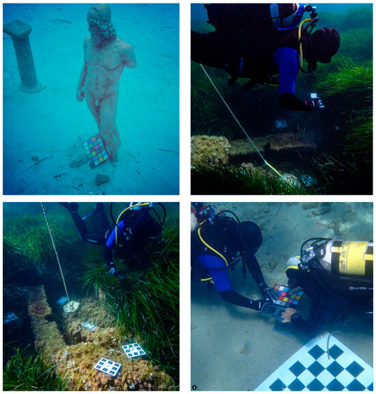
Figure 1.
Some practical examples of underwater photogrammetry applications.
Underwater photogrammetry has become one of the most affordable and widely adopted methods for documenting and reconstructing submerged archaeological assets. In the digital evolution of photogrammetry, images are captured to exploit (using computer-vision-based procedures such as image matching and Structure From Motion solutions) their intrinsic metric contents.
Despite its widespread adoption, underwater photogrammetry still faces significant challenges, especially in acquiring and processing underwater images. One challenge is that the documentation is often insufficient and must be supported by careful georeferencing and the consistent use of the same reference system [20]. Additionally, generating an accurate 3D replica of a surveyed object or site requires addressing specific issues, such as maintaining consistent radiometry and avoiding blurry, low-contrast, or over-/under-exposed images. To overcome these challenges, Costa [21] outlines several adaptations to photogrammetry techniques specifically for low-visibility environments, such as high-resolution cameras and strobe lighting, wide-field-of-view cameras, image stabilization and motion compensation, and image preprocessing techniques, such as noise reduction and denoising. These techniques can further improve image quality and reduce the impact of low-visibility conditions.
2.1. Preliminary Consideration in Underwater Photogrammetric Data Acquisition and Processing
Application considerations must be addressed to ensure the effectiveness and accuracy of a photogrammetric survey. In this section, we first discuss key factors such as application restrictions, reconstruction accuracy requirements, and the time involved in modeling. Then follows a brief description of the input data, the acquisition methods, and the processing algorithms used in underwater photogrammetry.
2.1.1. Acquisition Depth and Time Restrictions
The successful application of underwater photogrammetry is contingent upon various environmental factors influencing the operator’s ability to capture high-quality images and data. These factors include the depth of the sea, water clarity, and environmental conditions such as currents and visibility. Deeper water presents challenges for operators due to increased pressure, reduced visibility, and limited bottom time. The depth of the sea may necessitate specialized equipment and techniques to ensure safe and effective data acquisition. Water clarity plays a crucial role in the quality of images captured during photogrammetric surveys. Turbid or murky waters can obscure details and limit the accuracy of reconstructions. Operators may need to employ strategies such as artificial lighting or underwater filters to mitigate the effects of poor water clarity. Factors such as currents, tides, and weather conditions can impact the stability and safety of the survey environment. Operators must exercise caution and adapt their methodologies to account for these variables, ensuring the safety of personnel and equipment during data acquisition.
2.1.2. Photogrammetric Acquisition Methods
The fundamental input data for underwater photogrammetry consist of a carefully captured sequence of photographs taken from multiple viewpoints. These photographs should cover the target object or scene comprehensively, ensuring sufficient overlap between images to create a dense point cloud. This captured sequence of photographs should be of high quality with high resolution and low noise. The images should also be well exposed and have an accurate color balance. In addition, it is necessary to have sufficient overlap between the images so that the software can accurately determine the relationship between the different viewpoints. This overlap is typically between 50% and 80% [22]. It is important to acquire high-quality images of the underwater scene. This is typically carried out using a specialized underwater camera, such as a DSLR or mirrorless camera with housing and external strobes. There are two main methods for acquiring images for underwater photogrammetry:
Manual: Divers or underwater robots can manually capture images of the target using handheld or tethered cameras. This method is labor-intensive, and it can be difficult to control the camera’s position and orientation, but it can be used to capture high-quality images of intricate details [23].
Automated: Autonomous underwater vehicles (AUVs) or remotely operated vehicles (ROVs) can be programmed to fly or swim along a predefined path while photographing. This method is more efficient and allows for a wider coverage of the target. Still, it can be challenging to ensure that the AUV or ROV follows the path accurately and captures high-quality images [24].
2.1.3. Reconstruction Accuracy
Various parameters, including the camera-to-object distance, acquisition geometry, and sensor resolution, influence the reconstruction accuracy required for underwater cultural heritage surveys. Achieving high levels of accuracy is essential for producing detailed and reliable 3D models of surveyed assets. Maintaining an optimal camera-to-object distance is critical for capturing detailed images with sufficient overlap for accurate reconstruction. Operators must carefully plan their survey trajectories and camera positions to ensure consistent coverage of the target area. The arrangement and orientation of cameras relative to the subject impact the accuracy and completeness of the resulting 3D model. Different acquisition geometries, such as grid or spiral patterns, may be employed to optimize coverage and minimize distortion. The resolution of the imaging sensor used in photogrammetric surveys directly influences the level of detail captured in the resulting images. Higher-resolution sensors can enhance the accuracy of reconstructions but may also require greater computational resources for processing. It is important to specify that the accuracy of the survey will be certifiable only if enough GCPs (Ground Control Points), CPs (Check Points) and/or redundant scalebars are located in the surveyed area in order to correctly georeference the survey and the related products.
2.1.4. Processing Algorithms
The time required for modeling, encompassing the computation of the acquired data using photogrammetry and structure-from-motion software, is critical in underwater cultural heritage documentation projects. This time is influenced by the number of images captured, their resolution, and the scene’s complexity. Increasing the number of captured images can improve the final 3D model’s accuracy and completeness but also prolong the processing time. Operators must strike a balance between the data acquisition efficiency and computational resources. Higher-resolution images contain more detail but require more processing power and time for alignment and reconstruction. Operators should carefully consider the trade-offs between image resolution and processing efficiency.
The core processing algorithms in underwater photogrammetry are similar to those used in terrestrial photogrammetry, but they are adapted to address the specific challenges of an underwater environment. SfM algorithms reconstruct the 3D structure of a scene from a set of 2D photographs. They estimate the 3D coordinates of points in the scene by analyzing the relative positions of corresponding points in the images. A comprehensive overview of underwater 3D reconstruction technology based on optical images is provided in [25]
2.2. Optical and Physics Issues Related to Underwater Photogrammetry
For submerged heritage, for which it is necessary to work in a marine environment, the phase of the survey is one of the most important phases (together with the planning phase), as it helps understand not only the current state of the assets but also to make historical hypotheses and assumptions, as well as define the successive steps of valorization. Marine environments and conditions cause specific alterations that require the collaboration of different scientists in a multidisciplinary approach. Basic knowledge of the physical principles that regulate light transmission helps to understand the optical phenomena and the “countermeasures” to be adopted when performing a photogrammetric survey.
2.2.1. The Underwater Spectrum of Light and Selective Absorption
An important factor that influences a survey is the depth in which the assets are located; this is related to a degradation in the visible electromagnetic spectrum, and it is an important aspect for the study and recognition of materials, both for photographic and photogrammetric purposes.
Sunlight is electromagnetic radiation emitted by the Sun. It is a broad spectrum of electromagnetic waves, ranging from radio waves with wavelengths of tens of meters to gamma rays with wavelengths of less than a trillionth of a meter. The most intense portion of the Sun’s radiation that reaches the Earth’s surface is visible light, with wavelengths ranging from about 400 to 700 nanometers. The light spectrum is all the different wavelengths of light that compose sunlight. It is a continuous spectrum, meaning no gaps exist between the different wavelengths. The visible light spectrum is a small portion of the overall light spectrum, but it is the only portion we can see. Focusing on visible colors, these range from red to violet in the following order: red, orange, yellow, green, light blue, blue, and violet. Like many other substances, water absorbs part of the light that passes through it. This absorption is not homogeneous but occurs differently depending on the mass of water crossed by the light for the various colors. The phenomenon, precisely because it occurs selectively on the various colors, is called “selective absorption”.
Underwater images are, therefore, affected by inconsistencies in radiometry due to the optical properties of water. When light propagates in water, all (but mainly higher wavelengths) colors are affected by a degradation in intensity. As we mentioned, this degradation changes based on the examined wavelength, mainly concerning the acquisition depth, the camera-to-object distance, and the water’s physical characteristics and conditions for a given site in a specific acquisition time frame. Water causes a significant attenuation of light while it passes through it, making its intensity exponentially weaker the more it travels [26]. The attenuation of light underwater is frequency-dependent, meaning that red light is attenuated over much shorter distances than blue light, as well as the backscattering of blue and green, resulting in a change in the observed color of an object at different distances from the camera and light source [27].
Another factor that should not be underestimated is the presence of materials in the water; for example, if we consider the delta of a river or a lagoon environment [21], the suspended sand and clay particles will probably give the water a more turbid color, tending toward brown. The presence of phytoplankton is another cause of color distortion in underwater environments; in fact, it absorbs blue and red, resulting in a reflection of green. In practice, where there is water with phytoplankton, its color will be more green than blue. This seemingly useless information is extremely important; studying the color of the ocean allows scientists to assess the distribution and location of phytoplankton worldwide.
In digital cameras, the “white balance” feature allows the camera to interpret the colors appropriately by eliminating the chromatic dominants due to the light that, instead of being white, can be colored. White balance eliminates this unpleasant effect by returning more natural colors, which cannot happen when using film. Compared to traditional film photography, the advantage of digital images is that they automatically correct colors and give them more similar aspects to the real colors. However, there are some limits: the camera can reduce the intensity of a chromatic component, for example, blue, if this predominates over the others, but certainly cannot create red where it is absent.
This first problem can be partially solved by using the flash. Its white light allows it to revive even the dullest colors, but only at a certain distance. What happens with sunlight also happens with a flashlight. As mentioned earlier, colors are absorbed as a function of the amount of water the light passes through. It does not matter which direction the light comes from; what matters is the distance the light travels underwater (Figure 2).
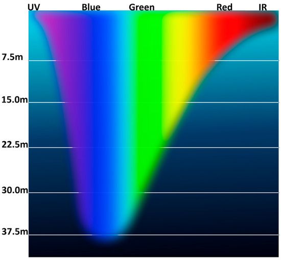
Figure 2.
The colorful rainbow bands that make up white light are absorbed/attenuated by liquid water at different rates. This graph attempts to approximate how deep certain colors of light penetrate. According to this graph, blue light penetrates deepest, while ultraviolet, red, and infrared are rapidly absorbed near the surface. Source: Wikimedia Commons; Author: Tomemorris, License: CC-BY-SA-4.0.
Another factor to be considered is the depth to the bottom. If we are in the middle of the ocean, the light will not be able to penetrate for more than a few hundred meters, so—in other words—we will not have any reflection of the bottom, and we will see the water as a dark and intense blue. If, on the other hand, we are close to the coast, we will see the water as a brilliant blue-turquoise due in part to the reflection of the seabed.
2.2.2. Diffusion and Backscattering
Diffusion is another important phenomenon that must be kept in mind, and it is related to the presence of suspended materials in the water. Microorganisms, such as plankton, are always present; in tropical areas, the period of coral reproduction is characterized by large numbers of eggs dispersed in the water, but the real issue is the sand. Whether raised from the seabed due to rough seas or carried, for example, by rivers, sand, more than anything else, can make an underwater panorama appear as if it were shrouded in fog. The light hitting the suspended materials is reflected in every direction so that everything appears blurred and lacks details. This phenomenon is, however, always present since the presence of suspended elements in water is a common factor.
Backscatter, or backscattering, is usually a diffuse reflection due to scattering. It refers to the light from a flash or strobe reflected from particles in the lens’ field of view, causing specks of light to appear in the photo. This gives rise to what are sometimes referred to as orb artifacts. Photo backscatter can result from snowflakes, rain, fog, or, in specific cases, suspension in a water medium [28]. Due to the size limitations of modern compact and ultra-compact cameras, especially digital cameras, the distance between the lenses and the built-in flash has decreased, thereby reducing the angle of reflection of light on the lenses and increasing the likelihood of reflection of the light from normally subvisible particles (Figure 3).
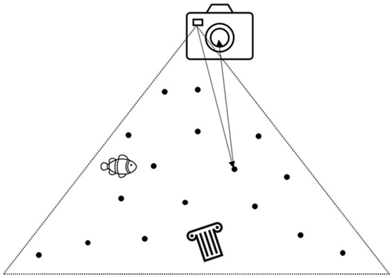
Figure 3.
Backscatter from a strobe near the lens.
Backscatter can be reduced by compensating for the strobing direction of the photo as far away from the corner of the lens as possible. This is normally done by placing the light source high and to one or both sides by placing the strobes on extendable arms. As the light comes from the sides, the reflected light is mainly in the direction of the strobe instead of the camera lens (Figure 4).
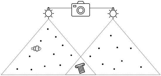
Figure 4.
Backscatter can be minimized by moving the strobe away from the lens.
To overcome the reduction in the details and sharpness of distant objects related to diffusion, it is necessary to work at a very short distance, thus photographing the object of interest while being close to it. However, an important fact remains: in normal cases, all lenses increase their focal length, thus reducing the FOV and forcing them to shoot from greater distances than for a land survey (to comply with the required overlap).
2.2.3. Reflection and Refraction of Light in Water
Refraction is the bending of light as it passes from one medium to another with a different refractive index. The refractive index of water is higher than the refractive index of air, so when light travels from air to water, it slows down. Depending on the angle at which the light hits the water’s surface, a greater or lesser part of the light will reach the bottom. According to the Snell–Descartes law, if the light arrives at a different inclination, only a part penetrates towards the bottom, while a part is reflected (Figure 5).
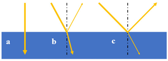
Figure 5.
Refraction of light at the water surface: perpendicular incidence (a); inclined incidence (b); and low sun angle (c).
It should also be noted that rays of light that do not reach the water’s surface vertically undergo a deviation. In fact, due to the lower speed of light in the water, they tend to change direction, approaching the line perpendicular to the surface that passes through the point where the rays hit the surface. When light rays passing from the air to the water are deflected, their direction becomes closer to the normal, and the opposite occurs when light passes from the air to the water. In that case, there is a deviation from the normal.
Light rays traveling from water to air tend to move away from the perpendicular line that passes through the point where the rays hit the surface. The law of refraction, generally known as the Snell–Descartes law, governs the deviation undergone by light rays when they pass through a distinct interface between air and water. It is described by the following Equation (1).
where:
= the angle of incidence;
= the angle of refraction;
= the refractive index of the first medium (approximately 1 for air);
= the refractive index of the second medium (comprised between 1.3330 and 1.3721, depending on the salinity of the water [29]).
It is important to consider that the random effect of surface ripples generates unpredictable a priori refractions and, therefore, is not modellable without considering a degree of approximation.
It has been said that objects appear closer; to determine the distance at which they appear (called apparent distance), knowing the real one, the value of this is divided by the refractive index of the medium.
2.2.4. Refraction in UW Photogrammetry: Flat and Dome Ports
The influence of refraction is also felt in underwater photogrammetry; everything, regarding human sight, appears closer or larger when underwater, and in the same way, this also happens for digital and traditional cameras. In this case, the most disadvantaged cameras, even if it is possible to implement countermeasures, are the DSLRs.
When a camera is used in a terrestrial environment, it has a characteristic field of view (FOV), and this does not undergo any variation. The focal length of the lens, together with the sensor size, determines the FOV. As previously discussed, when light encounters a water surface, it refracts or bends closer to the line perpendicular to the boundary between the water and the air at the glass surface.
This behavior will also occur when photographing, resulting in a lower FOV. Decreasing the FOV transforms the behavior of the lens, making it more similar to that of a telephoto lens (Figure 6).
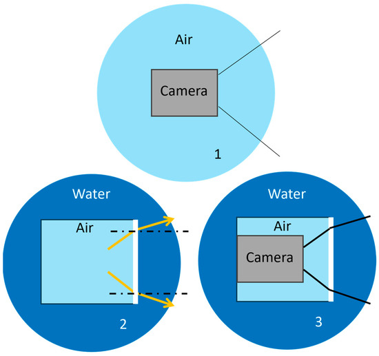
Figure 6.
When cameras are employed underwater, the light passing through the medium interface of water undergoes refraction effects. The result is a smaller FOV than that obtainable with the same lens used in a terrestrial environment (1 FOV in the air, 2 camera housing in the water and connected FOV, 3 FOV reduction in the water when camera is enclsed in a camera house). Reproduced from [30].
Dome ports are specialized underwater housings that utilize a hemispherical glass or acrylic structure to provide a wide field of view for cameras. They are commonly used in underwater photogrammetry applications to capture overlapping images that can be used to reconstruct 3D models of underwater objects or scenes [31]. Dome ports also have the advantage of being able to image more of a scene in a single photograph, which can save time and effort during the photogrammetry process. (Figure 7). It is always of great benefit, even if the qualitative improvement is more noticeable than for a flat port in combination with pushed wide-angle lenses (5). Each objective lens must also correspond to a specific type of porthole. Its curvature must be suitable for the focal length of the lens, and the center of the sphere of which the port is a part must coincide with the optical center of the lens, which is not necessarily in correspondence with the outermost lens. Therefore, a different porthole for each focal length is necessary (at least in theory). The same port is used for multiple lenses of different focal lengths.
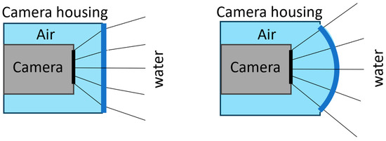
Figure 7.
Comparison between a case with a flat port and one with a dome port. Examining the behavior of the light rays that pass through the glass and the window, it is evident that they do not undergo deviations when they pass through perpendicular to the surface. The shooting angle and the underwater focal length do not vary. Reproduced from [30].
There are glass or acrylic glass portholes on the market, including plexiglass with particular optical characteristics, and there are pros and cons for each of the two. Those in crystal (glass) are generally more robust, given the hardness of the material. The optical characteristics of the two materials are still excellent, but there are economic and practical differences. If glass portholes are more resistant, the difference in density between glass and water makes any scratches more evident than with plastic portholes. Thanks to their density similar to that of water and, therefore, their similar optical behavior, these materials can mask those small scratches produced on the external surface with use. It should be considered that a plastic porthole, given its simpler workability, is generally cheaper than glass ones.
2.3. Optical and Physics Issues Related to Underwater Photogrammetry
2.3.1. Geometric Aspects of Underwater Imaging and Stereo Reconstruction
Stereo reconstruction involves studying the mathematical principles governing acquiring and interpreting 3D information from underwater environments [32]. Underwater imaging systems, such as cameras and sonars, capture distorted and noisy data due to the unique properties of light and sound propagation in water [33]. To overcome these challenges and reconstruct accurate 3D models, it is essential to understand the geometric distortions and noise characteristics that affect underwater data (Figure 8).
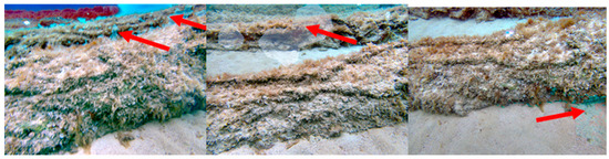
Figure 8.
Examples of artifacts (indicated by the red arrows) due to poor model quality and inaccurate range maps.
The propagation of light and sound in water introduces several distortions that can significantly impact underwater imaging and stereo reconstruction. In addition to distortions, noise is another major challenge in underwater imaging and stereo reconstruction. One of the main causes of noise in underwater photogrammetry is light attenuation. Light travels less efficiently in water than in air, so the amount of light reaching the camera decreases with depth (Figure 9). This can make capturing sharp images difficult and introduce noise into the image data [34].
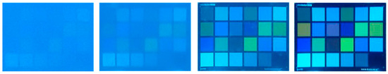
Figure 9.
An example of light attenuation, which is related to the camera-to-object distance. The same calibration chart is photographed from left to right, increasing the camera’s proximity to the chart.
Another major source of noise in underwater photogrammetry is scattering. When light passes through water, it can be scattered by particles suspended in the water, such as plankton and suspended sediment. This scattering can cause the image to become hazy and introduce noise into the image data [35].
In addition to light attenuation and scattering, several other factors can cause noise in underwater photogrammetry. These include the following:
- Camera motion: Any camera movement, underwater or on the surface, can cause blur and noise in images. This is particularly important for underwater photogrammetry, as the water can make it difficult to keep the camera steady.
- Waves and currents: Waves and currents can cause underwater objects to move, leading to blurring in underwater photographs. This can also make it difficult to stitch together multiple photographs to create a complete 3D model.
- Reflections: Underwater surfaces can reflect light, creating distracting photograph artifacts. These reflections can also make identifying features in the image data difficult (Figure 10).
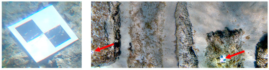 Figure 10. Examples of artifacts (indicated by the red arrows) due to reflections caused by the albedo of artificial objects.
Another relevant issue concerning the geometric aspect of underwater imaging, especially when operating in shallow waters, is the presence of caustics. Caustics are bright, localized patterns that occur when a curved surface reflects or refracts light rays. They are a common phenomenon in underwater photogrammetry and can be a major challenge in creating accurate 3D models (Figure 11).
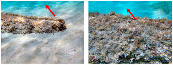
Figure 11.
An example of caustics (indicated by the red arrows), which are often present in underwater imagery acquired at shallow depths.
Caustics can be difficult to remove from underwater photogrammetry images because they can be very similar to real features of the object or scene. However, several techniques can be used to reduce their impact [36].
Lens aberrations are another common problem in underwater photogrammetry and can significantly impact the accuracy and quality of 3D models [37]. They occur when light rays passing through a lens do not converge perfectly in the image plane, which results in distortions in the image.
Despite the challenges posed by distortions and noise, geometric principles can be applied to mitigate these effects and achieve accurate underwater 3D reconstruction. These principles include the following:
- Calibration: The accurate calibration of underwater imaging systems is essential to account for geometric distortions and ensure the correct alignment of images or signals from multiple sensors [38].
- Dewarping: Dewarping algorithms can correct refraction and other geometric distortions in underwater images or signals [39].
- Noise reduction: Various noise reduction techniques, such as filtering and averaging, can be applied to reduce the impact of electronic and environmental noise on underwater data [40].
- Stereo reconstruction: Stereo reconstruction algorithms can fuse images or signals from multiple underwater sensors to reconstruct a 3D model of the scene [41].
To ensure metric consistency and obtain reliable 3D metric products, it is essential to follow photogrammetric principles, especially in underwater photogrammetry. The proper geometric calibration of the employed optics is essential with the widespread use of low-cost and non-metric sensors.
2.3.2. Camera Calibration
Calibration identifies geometric distortions in final images caused by the lens materials, shapes, and construction characteristics of the cameras and optics used in the survey.
Camera calibration for photogrammetry is a well-known practice [42] and is an essential preliminary step for accurate 3D object reconstruction. It allows for obtaining intrinsic camera parameters (f, cx, cy, k1, k2, k3, k4, b1, b2, p1, p2) that describe the interior orientation and lens distortion. Knowing these parameters is essential for generating images as close as possible to central perspectives, which are necessary for metric purposes.
The following calibration parameters can be determined:
- f—the focal length.
- cx and cy—the principal point coordinates, i.e., lens optical axis intersection coordinates with sensor plane.
- b1 and b2—the affinity and non-orthogonality (skew) coefficients.
- k1, k2, k3, and k4—the radial distortion coefficients.
- p1 and p2—the tangential distortion coefficients.
Various methods and strategies exist for calibrating digital cameras in photogrammetry. The most common approach is to use computer vision algorithms to perform camera self-calibration [43]. This approach can substantially improve accuracy [44], even with non-metric and non-conventional low-cost photogrammetric sensors [45].
Pre-calibration can be used when the conditions do not change significantly between the calibration and the survey. In pre-calibration, the camera is calibrated in a controlled environment (using a calibration polygon) or with ad hoc procedures (using calibration panels with checkerboard or dot patterns). This provides a set of intrinsic parameters that can be used as an initial guess during the self-calibration phase performed before or during the bundle block adjustment (BBA) in a typical photogrammetric workflow.
While self-calibration is the most common approach in data acquisition situations, especially in archaeology [46], it is still possible to observe a significant gain in survey accuracy whenever a robust self-calibration procedure is conducted [47]. This is especially important for underwater photogrammetric surveys, where additional distortions are introduced due to the different refractive indexes of water and air and the geometric characteristics of the flat or dome port that may be used [31].
2.4. Radiometric Correction of Images
Underwater image color correction is an important area of research for disciplines such as underwater archaeology and marine biology. Domain experts and scientists need images with colors that are consistent with the real-world scene. Automatic and semi-automatic color correction methods and algorithms have been developed to meet this need and are mainly used in the pre- or post-processing phases of photogrammetry [19,27,48,49,50,51].
Image enhancement and restoration methods have been proposed for many years. This section will provide an overview of these methods and their relevance to the investigated topic.
Water absorption and scattering coefficients have been a topic of scientific interest for many years. In 1951, Jerlov classified waters into three oceanic and five coastal types based on these coefficients [52]. Since then, various methods have been developed to determine the inherent optical properties of Jerlov water types [53,54].
A mathematical model for the spectral analysis of water characteristics was proposed in 2014 [55]. This model can be used to determine the inherent optical properties of water, which can then be used for underwater image color correction [54]. Natural water bodies were used to determine the positions of all physically important RGB attenuation coefficients. They showed that the range of wideband attenuation coefficients in the ocean is limited and that the transition from wavelength-dependent attenuation β(λ) to wideband attenuation β(c) is more complex than previously thought. A simple fusion-based approach for enhancing underwater images was proposed in [56]. This method uses a single input image and blends multiple well-known filters to improve the image quality. The authors showed that this method effectively improves the underwater footage of dynamic scenes.
A first proposal for the color correction of UW images using the lαβ color space is presented in [49]. This method white-balances the chromatic components and performs histogram cut-off and stretching of the luminance component to increase image contrast. The method works well under the assumption of a gray world and homogeneous lighting of the scene, which is acceptable only for close-range acquisition in a downward direction, such as seabed mapping or UW photography, and in situations with slight light changes.
Bryson et al. [48] proposed an automated underwater image color correction method using a gray-world color distribution. This means that surface reflectance has a gray-scale distribution independent of scene geometry. This approach is particularly useful for imaging large-scale biological environments, where the use of color charts is prohibited due to the sensitivity of marine ecosystems to seabed disturbances.
Another underwater image color correction approach is to develop a physically based image formation model. This model considers the optical properties of water, such as absorption and scattering, to calculate the true color of a scene. In 2016, researchers proposed a formation model for calculating the true color of scenes taken from an underwater automated vehicle with strobes. This model required a unique camera setup and strobes, but it allowed the authors to create and propose a unique image formation model that could restore the true color of the images.
Akkaynak et al. [57] proposed a revised underwater image formation model that takes into account these differences. They derived the physically valid space of backscatter using oceanographic measurements and validated their model using in situ underwater experiments.
The revised model is more physically accurate than the current one but contains more parameters and can be challenging. However, the researchers also implemented a pipeline called Sea-thru [19] that uses the revised model to correct the colors of underwater images.
In 2021, Valchos et al. [58] proposed a mathematical method to color-correct underwater images by modeling light backscattering and absorption variation according to the distance of the surveyed object.
Another iteration of the latter is SeaThru-NeRF [59], a new rendering model for NeRFs in scattering media, which is based on the SeaThru image formation model and suggests a suitable architecture for learning both scene information and medium parameters 1. In 2023, Jamieson et al. proposed DeepSeeColor [60]. This novel algorithm combines a state-of-the-art underwater image formation model with the computational efficiency of deep learning frameworks. In their experiments, they show that DeepSeeColor offers comparable performance to the popular “Sea-Thru” algorithm while being able to rapidly process images at up to 60 Hz, thus making it suitable for use onboard AUVs as a preprocessing step to enable more robust vision-based behaviors 2.
3. The Use of Drones in Underwater Photogrammetry
3.1. UAS Photogrammetry in Very Shallow Water
To plan an effective archaeological survey campaign, it is essential to understand the topographic situation of a site, both to obtain an overview of the area and to comprehend the relationships between the surrounding territory and the underwater heritage itself. A hybrid approach integrating total stations and GNSS equipment for land surveys remains fundamental [61].
Aerial photography is an important tool for this purpose, as it can be used for both land surveys and the shallow water mapping of archaeological evidence. This is important not only to identify the presence of archaeological sites but also to better understand the layout of structures. Aerial photogrammetry, including legacy data, represents a cartographic basis for drafting an overall plan for the site.
For sites with assets halfway between water and land or with emerged and submerged portions, it is particularly important to study the relationship between the coast and the land to identify elements that may suggest continuity, or continuation. Here again, aerial photogrammetry plays an important role in understanding the limits of archaeological structures on land and underwater, which is essential for better planning subsequent surveys.
UAS (Unmanned Aerial System) photogrammetry has emerged as a powerful tool for archaeological surveys in very shallow water, offering a cost-effective and efficient way to perform bathymetric surveys [62]. However, the unique characteristics of shallow water environments pose several challenges for UAS photogrammetry, particularly the effects of refraction and waves [63].
In the case of UAS photogrammetry in shallow water, the difference in refractive index between air and water causes light rays to bend towards the water’s surface, leading to distortion in the captured images. This distortion can result in errors in the reconstructed 3D models, affecting the accuracy of archaeological interpretations.
Waves on the water surface introduce additional challenges for UAS photogrammetry. The movement of waves can cause blurry or distorted images. Additionally, the rippling effect of waves can create artifacts in the reconstructed 3D models, affecting the visual interpretation of the archaeological site.
To mitigate the effects of refraction and waves, Partama [64] developed geometric modeling techniques specifically tailored for UAS photogrammetry in shallow water. These techniques involve incorporating the refractive index of water and wave characteristics into the photogrammetry software. This allows the software to compensate for the distortion caused by refraction and waves, resulting in more accurate 3D reconstructions [65]. Other solutions are represented by bathymetric mapping from UAS imagery based on machine learning [66] to automatically compensate for water refraction and wave motion.
Overall, these studies have demonstrated the effectiveness of geometric modeling in mitigating the effects of refraction and waves, leading to more accurate and reliable 3D reconstructions of underwater archaeological sites in very shallow waters.
3.2. Remotely Operated Vehicles (ROVs) in Underwater Photogrammetry
Remotely operated vehicles (ROVs) have emerged as powerful tools for underwater exploration and surveying, particularly in the context of underwater photogrammetry. Their ability to navigate underwater environments and acquire high-resolution imagery has transformed our ability to study underwater structures, habitats, and ecosystems. Unlike human divers, ROVs can operate in hazardous or inaccessible environments, providing a safer and more efficient means of data collection.
ROVs come in various sizes and configurations, catering to specific applications and depths. Smaller ROVs, known as mini ROVs, are typically used for shallow-water operations, while larger ROVs can venture into deeper waters. Some ROVs are designed for specific tasks, such as inspecting and maintaining underwater infrastructure, while others are more versatile for a wider range of applications.
ROVs offer several advantages over traditional underwater photogrammetry methods such as scuba diving and towed cameras:
- Enhanced safety: ROVs eliminate the risks associated with human divers, such as decompression sickness, entanglement, and hazardous marine life encounters.
- Deeper reach: ROVs can operate at depths beyond the reach of human divers, providing access to a wider range of underwater environments.
- Increased flexibility: ROVs can navigate complex underwater structures and environments with greater maneuverability than towed cameras.
- Automated data acquisition: ROVs can be programmed to follow predetermined paths and capture images autonomously, reducing operator fatigue and increasing efficiency.
ROVs have found widespread applications in underwater photogrammetry for various purposes, including documenting underwater shipwrecks, submerged settlements, and archaeological sites [67]; assessing coral reef health, studying marine habitats, and monitoring the impact of human activities [68]; and examining pipelines, dams, and other underwater structures for cracks, corrosion, or other damage [69].
4. Discussions
Underwater cultural sites are among the most difficult-to-reach heritage sites due to their intrinsic nature. The difficulty of operating in water environments is further compounded by the operator’s reduced stay time on the site and environmental conditions that can affect the survey, such as light conditions and water turbidity.
Geomatics provides sensors and techniques that allow scientists and professionals to record, process, and efficiently present data related to underwater archaeological sites. While the potentialities and problems of these techniques have already been addressed in the past [70], new emerging sensors and applications necessitate the continued investigation and evaluation of different approaches. The adoption of low-cost sensors is becoming more common [71], and the possibility of processing and quickly obtaining photogrammetric point clouds cannot be separated from the need for high metric accuracy, which is necessary for a trustworthy survey in cultural heritage documentation [72]. As such, multi-image photogrammetry has proven to be an affordable methodology, supporting underwater archaeological activities with reliable results [73].
An important outcome of an accurate metric survey is the production of thematic maps relative to materials, conservation status, and so forth, with a methodology like the one adopted on land. Developing appropriate surveys is the basis for scheduling conservative restoration actions [74]. Such restoration activities must consider that biological colonisations also endanger underwater ruins (in the short term). For this reason, it is important to take action through an initial survey and constant monitoring over time, which is functional to conserving heritage.
Over the years, some research has tried to provide a suitable methodology for satisfying the required metric accuracy and fieldwork surveys in the archaeological domain. Despite consolidated methodologies and standards in terrestrial surveys, some gaps and shortcomings exist in the underwater environment. Firstly, there is a lack of solutions for providing an easy-to-deploy workflow for expert domains (archaeologists) with no proficiency in geomatics to conduct further research on the acquired data, for example, 3D model inspection and the multitemporal analysis of excavated sites and their contents. By investigating accuracy, fidelity, and interpretive biases inherent in digital reconstructions, Ref. [11] underscores the importance of maintaining a nuanced perspective when utilizing digital tools in archaeological research. This work contributes significantly to ongoing discussions within the field, offering valuable insights for archaeologists and scholars grappling with the challenges of integrating digital technologies into underwater archaeological practice. Moreover, it is crucial to evaluate different strategies for dissemination using tools for 3D model sharing and visualization, not only for scientists but also for the general public. Nevertheless, it is currently possible to speed up and make UCH metric documentation more cost-effective, guaranteeing safety conditions during underwater operations simultaneously, thanks to underwater photogrammetry integrating various types of cameras and sensors.
Even if an accurate survey is important for underwater archaeology, it must link the archaeological knowledge to the surveyed geometry. So, not only must computer science be involved, but it is always fundamental to insert archaeological knowledge into the process [75].
Innovative monitoring and surveying procedures can promote underwater tourism, which combines single-activity leisure, sport, culture, and ecology, which makes it very profitable and highly sustainable, and the remote enjoyment of archaeological contexts. The exploitation of 3D reconstruction, remote visits, and virtual explorations serves as a tool for managing the cultural–natural heritage of underwater archaeological findings and maps areas from a new perspective (as an ethical obligation) based on the participatory approach of all the local stakeholders.
5. Conclusions
The take-home message is that photogrammetry is increasingly used in underwater archaeology to document, reconstruct, and restore underwater assets virtually [76]. When correctly adopted, this technology can make underwater sites more accessible to more people. It can also be used to track changes in the conditions of these sites over time, as well as foster the dissemination and promotion of UCH.
Photogrammetry can measure distances, areas, and volumes of objects and features in a marine environment. These data can be used to assess the conditions of marine structures, track changes over time, and develop conservation plans. For example, photogrammetry can measure the size and shape of coral reefs, track changes in coral cover, and assess the impact of human activities on coral reefs. Photogrammetry can also be used to record the appearance and condition of marine features. These data can be used to document marine sites’ historical and cultural significance, assess the impact of human activities, and develop educational resources. For example, photogrammetry can be used to record shipwrecks’ appearance, assess underwater pipelines’ condition, and document the diversity of marine life.
Increasing knowledge is the basis for every act of protection and valorization of archaeological and natural heritage. When facing the complex study of the conservation of underwater heritage and the coastal landscape, it is important to develop investigation and survey techniques (such as bathymetry, photogrammetry, and so forth) that require the integration of several disciplines, not only for the evaluation of the causes of the submersion but also for the definition of the important relations between underwater archaeological remains and those on the shore, taking into account the historical and chronological data available and always considering natural and anthropic factors. The objectives above go towards the efficient and effective protection and valorization of heritage.
However, some challenges still need to be addressed to make photogrammetry more effective for underwater archaeology. These challenges include developing more accurate and user-friendly workflows for archaeologists, integrating archaeological knowledge into the photogrammetry process, and overcoming the limitations of topographic surveys underwater. Another of those limits is related to the constraints of topographic surveys underwater; topographic measurement operations are often difficult and expensive to conduct, and the results can be inaccurate and limited by time, depth, and environmental conditions. During the integration of both direct and indirect survey data, it is crucial to gather and structure all the information in a way that can be understood and managed not only by geomatics but also by domain experts (archaeologists, marine biologists, etc.). Underwater cameras and dome ports specifically made for marine environments are essential for lowering geometric errors related to the presence of two mediums, which might affect the reconstruction results.
Despite these challenges, photogrammetry is a promising tool that has the potential to revolutionize underwater archaeology. With further development, this technology could lead to a better understanding of underwater heritage and a more effective approach to its preservation.
Author Contributions
Conceptualization, A.C. and F.C.; methodology, A.C.; investigation, A.C.; resources, A.C.; data curation, A.C.; writing—original draft preparation, A.C.; writing—review and editing, A.C. and F.C.; supervision, F.C. All authors have read and agreed to the published version of the manuscript.
Funding
This research received no external funding.
Institutional Review Board Statement
Not applicable.
Informed Consent Statement
Not applicable.
Data Availability Statement
The data presented in this study are available on request from the corresponding author.
Conflicts of Interest
The authors declare no conflicts of interest.
Notes
| 1 | https://github.com/deborahLevy130/seathru_NeRF (accessed on 1 February 2024) |
| 2 | https://github.com/warplab/DeepSeeColor (accessed on 1 February 2024) |
References
- Rissolo, D.; Blank, A.N.; Petrovic, V.; Arce, R.C.; Jaskolski, C.; Erreguerena, P.L.; Chatters, J.C. Novel Application of 3D Documentation Techniques at a Submerged Late Pleistocene Cave Site in Quintana Roo, Mexico. In Proceedings of the 2015 Digital Heritage, Granada, Spain, 28 September–2 October 2015; Institute of Electrical and Electronics Engineers (IEEE): Piscataway, NJ, USA, 2016; pp. 181–182. [Google Scholar]
- Menna, F.; Agrafiotis, P.; Georgopoulos, A. State of the Art and Applications in Archaeological Underwater 3D Recording and Mapping. J. Cult. Herit. 2018, 33, 231–248. [Google Scholar] [CrossRef]
- Violante, C. A Geophysical Approach to the Fruition and Protection of Underwater Cultural Landscapes. Examples from the Bay of Napoli, Southern Italy. In La Baia di Napoli. Strategie per la Conservazione e la Fruizione del Paesaggio Culturale; Editori Paparo: Napoli, Italy, 2023; pp. 66–73. [Google Scholar]
- Ricca, M.; Alexandrakis, G.; Bonazza, A.; Bruno, F.; Davidde Petriaggi, B.; Elkin, D.; Lagudi, A.; Nicolas, S.; Novák, M.; Papatheodorou, G.; et al. A Sustainable Approach for the Management and Valorization of Underwater Cultural Heritage: New Perspectives from the TECTONIC Project. Sustainability 2020, 12, 5000. [Google Scholar] [CrossRef]
- Ricci, R.; Francucci, M.; De Dominicis, L.; Ferri de Collibus, M.; Fornetti, G.; Guarneri, M.; Nuvoli, M.; Paglia, E.; Bartolini, L. Techniques for Effective Optical Noise Rejection in Amplitude-Modulated Laser Optical Radars for Underwater Three-Dimensional Imaging. EURASIP J. Appl. Signal Process. 2010, 2010, 958360. [Google Scholar] [CrossRef]
- Bartolini, L.; De Dominicis, L.; de Collibus, M.F.; Fornetti, G.; Guarneri, M.; Paglia, E.; Poggi, C.; Ricci, R. Underwater Three-Dimensional Imaging with an Amplitude-Modulated Laser Radar at a 405 Nm Wavelength. Appl. Opt. 2005, 44, 7130–7135. [Google Scholar] [CrossRef] [PubMed]
- Skarlatos, D.; Agrafiotis, P.; Balogh, T.; Bruno, F.; Castro, F.; Petriaggi, B.D.; Demesticha, S.; Doulamis, A.; Drap, P.; Georgopoulos, A.; et al. Project iMARECULTURE: Advanced VR, iMmersive Serious Games and Augmented REality as Tools to Raise Awareness and Access to European Underwater CULTURal heritagE. In Digital Heritage. Progress in Cultural Heritage: Documentation, Preservation, and Protection; Ioannides, M., Fink, E., Moropoulou, A., Hagedorn-Saupe, M., Fresa, A., Liestøl, G., Rajcic, V., Grussenmeyer, P., Eds.; Lecture Notes in Computer Science; Springer International Publishing: Cham, Switzerland, 2016; Volume 10058, pp. 805–813. ISBN 978-3-319-48495-2. [Google Scholar]
- Opdebeeck, J. Shipwrecks and Amphorae: Their Relationship with Trading Routes and the Roman Economy in the Mediterranean; University of Southampton: Southampton, UK, 2005. [Google Scholar]
- Auriemma, R.; Quiri, E. Importazioni Di Anfore Orientali Nell’Adriatico Tra Primo e Medio Impero. In Transport Amphorae and Trade in the Western Mediterranean; J. Eiring e J. Lund: Athens, Greece, 2004. [Google Scholar]
- Marín-Buzón, C.; Pérez-Romero, A.; López-Castro, J.L.; Ben Jerbania, I.; Manzano-Agugliaro, F. Photogrammetry as a New Scientific Tool in Archaeology: Worldwide Research Trends. Sustainability 2021, 13, 5319. [Google Scholar] [CrossRef]
- McAllister, M. The Problem with “digital Realism” in Underwater Archaeology: Photogrammetric Digital 3D Visualization and Interpretation. J. Marit. Archaeol. 2021, 16, 253–275. [Google Scholar] [CrossRef]
- Skarlatos, D.; Agrafiotis, P. Image-Based Underwater 3D Reconstruction for Cultural Heritage: From Image Collection to 3D. Critical Steps and Considerations. In Visual Computing for Cultural Heritage; Springer: Cham, Switzerland, 2020; pp. 141–158. [Google Scholar]
- Abate, N.; Ronchi, D.; Vitale, V.; Masini, N.; Angelini, A.; Giuri, F.; Minervino Amodio, A.; Gennaro, A.M.; Ferdani, D. Integrated Close Range Remote Sensing Techniques for Detecting, Documenting, and Interpreting Lost Medieval Settlements under Canopy: The Case of Altanum (RC, Italy). Land 2023, 12, 310. [Google Scholar] [CrossRef]
- Ceccarelli, S.; Guarneri, M.; Ferri de Collibus, M.; Francucci, M.; Ciaffi, M.; Danielis, A. Laser Scanners for High-Quality 3D and IR Imaging in Cultural Heritage Monitoring and Documentation. J. Imaging 2018, 4, 130. [Google Scholar] [CrossRef]
- Di Stefano, F.; Torresani, A.; Farella, E.M.; Pierdicca, R.; Menna, F.; Remondino, F. 3D Surveying of Underground Built Heritage: Opportunities and Challenges of Mobile Technologies. Sustainability 2021, 13, 13289. [Google Scholar] [CrossRef]
- Pulido Mantas, T.; Roveta, C.; Calcinai, B.; di Camillo, C.G.; Gambardella, C.; Gregorin, C.; Coppari, M.; Marrocco, T.; Puce, S.; Riccardi, A.; et al. Photogrammetry, from the Land to the Sea and Beyond: A Unifying Approach to Study Terrestrial and Marine Environments. J. Mar. Sci. Eng. 2023, 11, 759. [Google Scholar] [CrossRef]
- Calantropio, A.; Chiabrando, F.; Seymour, B.; Kovacs, E.; Lo, E.; Rissolo, D. Image Pre-Processing Strategies for Enhancing Photogrammetric 3d Reconstruction of Underwater Shipwreck Datasets. ISPRS—Int. Arch. Photogramm. Remote Sens. Spat. Inf. Sci. 2020, 43B2, 941–948. [Google Scholar] [CrossRef]
- Doležal, M.; Vlachos, M.; Secci, M.; Demesticha, S.; Skarlatos, D.; Liarokapis, F. Understanding Underwater Photogrammetry For Maritime Archaeology through Immersive Virtual Reality. Int. Arch. Photogramm. Remote Sens. Spatial Inf. Sci. 2019, XLII-2-W10, 85–91. [Google Scholar] [CrossRef]
- Akkaynak, D.; Treibitz, T. Sea-Thru: A Method for Removing Water from Underwater Images. In Proceedings of the 2019 IEEE/CVF Conference on Computer Vision and Pattern Recognition (CVPR), Long Beach, CA, USA, 15–20 June 2019; pp. 1682–1691. [Google Scholar]
- Balletti, C.; Beltrame, C.; Costa, E.; Guerra, F.; Vernier, P. Underwater photogrammetry and 3d reconstruction of marble cargos shipwreck. Int. Arch. Photogramm. Remote Sens. Spat. Inf. Sci. 2015, XL-5/W5, 7–13. [Google Scholar] [CrossRef]
- Costa, E. Survey and Photogrammetry in Underwater Archaeological Contexts at Low Visibility in the Venice Lagoon. Digit. Appl. Archaeol. Cult. Herit. 2022, 24, e00215. [Google Scholar] [CrossRef]
- Sapirstein, P.; Murray, S. Establishing Best Practices for Photogrammetric Recording during Archaeological Fieldwork. J. Field Archaeol. 2017, 42, 337–350. [Google Scholar] [CrossRef]
- McCarthy, J.; Benjamin, J. Multi-Image Photogrammetry for Underwater Archaeological Site Recording: An Accessible, Diver-Based Approach. J. Marit. Archaeol. 2014, 9, 95–114. [Google Scholar] [CrossRef]
- Livanos, G.; Zervakis, M.; Chalkiadakis, V.; Moirogiorgou, K.; Giakos, G.; Papandroulakis, N. Intelligent Navigation and Control of a Prototype Autonomous Underwater Vehicle for Automated Inspection of Aquaculture Net Pen Cages. In Proceedings of the 2018 IEEE International Conference on Imaging Systems and Techniques (IST), Krakow, Poland, 16–18 October 2018; pp. 1–6. [Google Scholar]
- Hu, K.; Wang, T.; Shen, C.; Weng, C.; Zhou, F.; Xia, M.; Weng, L. Overview of Underwater 3D Reconstruction Technology Based on Optical Images. J. Mar. Sci. Eng. 2023, 11, 949. [Google Scholar] [CrossRef]
- Jaffe, J.S. Computer Modeling and the Design of Optimal Underwater Imaging Systems. IEEE J. Ocean. Eng. 1990, 15, 101–111. [Google Scholar] [CrossRef]
- Bryson, M.; Johnson-Roberson, M.; Pizarro, O.; Williams, S.B. True Color Correction of Autonomous Underwater Vehicle Imagery. J. Field Robot. 2016, 33, 853–874. [Google Scholar] [CrossRef]
- Van Damme, T. Computer vision photogrammetry for underwater archaeological site recording in a low-visibility environment. Int. Arch. Photogramm. Remote Sens. Spat. Inf. Sci. 2015, XL-5-W5, 231–238. [Google Scholar] [CrossRef]
- Lide, D. Handbook of Chemistry and Physics, 86th ed.; CRC: Boca Raton, FL, USA, 2005. [Google Scholar]
- Borri, E.M. Fotografia Subacquea per Turisti Digitali; Edizioni FAG Srl: Assago, Italy, 2005; ISBN 978-88-8233-433-8. [Google Scholar]
- Menna, F.; Nocerino, E.; Remondino, F. Flat Versus Hemispherical Dome Ports in Underwater Photogrammetry. ISPRS—Int. Arch. Photogramm. Remote Sens. Spat. Inf. Sci. 2017, 42W3, 481–487. [Google Scholar] [CrossRef]
- Bruno, F.; Bianco, G.; Muzzupappa, M.; Barone, S.; Razionale, A.V. Experimentation of Structured Light and Stereo Vision for Underwater 3D Reconstruction. ISPRS J. Photogramm. Remote Sens. 2011, 66, 508–518. [Google Scholar] [CrossRef]
- Telem, G.; Filin, S. Photogrammetric Modeling of Underwater Environments. ISPRS J. Photogramm. Remote Sens. 2010, 65, 433–444. [Google Scholar] [CrossRef]
- Karpouzli, E.; Malthus, T.; Place, C.; Chui, A.M.; Garcia, M.I.; Mair, J. Underwater Light Characterisation for Correction of Remotely Sensed Images. Int. J. Remote Sens. 2003, 24, 2683–2702. [Google Scholar] [CrossRef]
- Cheng, H.; Chu, J.; Zhang, R.; Tian, L.; Gui, X. Turbid Underwater Polarization Patterns Considering Multiple Mie Scattering of Suspended Particles. Photogramm. Eng. Remote Sens. 2020, 86, 737–743. [Google Scholar] [CrossRef]
- Agrafiotis, P.; Skarlatos, D.; Forbes, T.; Poullis, C.; Skamantzari, M.; Georgopoulos, A. Underwater photogrammetry in very shallow waters: Main challenges and caustics effect removal. Int. Arch. Photogramm. Remote Sens. Spat. Inf. Sci. 2018, XLII–2, 15–22. [Google Scholar] [CrossRef]
- Menna, F.; Nocerino, E.; Remondino, F. Optical Aberrations in Underwater Photogrammetry with Flat and Hemispherical Dome Ports. In Proceedings of the Videometrics, Range Imaging, and Applications XIV, Munich, Germany, 25–29 June 2017; SPIE: St Bellingham, WA, USA, 2017; Volume 10332, pp. 28–41. [Google Scholar]
- Lavest, J.M.; Rives, G.; Lapresté, J.T. Underwater Camera Calibration. In Computer Vision—ECCV 2000; Vernon, D., Ed.; Springer: Berlin/Heidelberg, Germany, 2000; pp. 654–668. [Google Scholar]
- Simple Algorithm for Correction of Geometrically Warped Underwater Images—Halder—2014—Electronics Letters—Wiley Online Library. Available online: https://ietresearch.onlinelibrary.wiley.com/doi/full/10.1049/el.2014.3142 (accessed on 22 December 2023).
- Jian, M.; Liu, X.; Luo, H.; Lu, X.; Yu, H.; Dong, J. Underwater Image Processing and Analysis: A Review. Signal Process. Image Commun. 2021, 91, 116088. [Google Scholar] [CrossRef]
- Queiroz-Neto, J.P.; Carceroni, R.; Barros, W.; Campos, M. Underwater Stereo. In Proceedings of the Proceeding. 17th Brazilian Symposium on Computer Graphics and Image Processing, Curitiba, Brazil, 20 October 2004; pp. 170–177. [Google Scholar]
- Remondino, F.; Fraser, C. Digital Camera Calibration Methods: Considerations and Comparisons. Int. Arch. Photogramm. Remote Sens. Spat. Inf. Sci. 2006, XXXVI, 266–272. [Google Scholar] [CrossRef]
- Fraser, C.S. Digital Camera Self-Calibration. ISPRS J. Photogramm. Remote Sens. 1997, 52, 149–159. [Google Scholar] [CrossRef]
- Gruen, A.; Beyer, H.A. System Calibration Through Self-Calibration. In Calibration and Orientation of Cameras in Computer Vision; Gruen, A., Huang, T.S., Eds.; Springer Series in Information Sciences; Springer: Berlin/Heidelberg, Germany, 2001; pp. 163–193. ISBN 978-3-662-04567-1. [Google Scholar]
- Perfetti, L.; Polari, C.; Fassi, F. Fisheye multi-camera system calibration for surveying narrow and complex architectures. Int. Arch. Photogramm. Remote Sens. Spatial Inf. Sci. 2018, XLII–2, 877–883. [Google Scholar] [CrossRef]
- Rodríguez-Martín, M.; Rodríguez-Gonzálvez, P. Suitability of Automatic Photogrammetric Reconstruction Configurations for Small Archaeological Remains. Sensors 2020, 20, 2936. [Google Scholar] [CrossRef] [PubMed]
- Fryer, J.G.; Fraser, C.S. On the Calibration of Underwater Cameras. Photogramm. Rec. 1986, 12, 73–85. [Google Scholar] [CrossRef]
- Bryson, M.; Johnson-Roberson, M.; Pizarro, O.; Williams, S.B. Colour-Consistent Structure-from-Motion Models Using Underwater Imagery. Robot. Sci. Syst. 2013, 8, 33–40. [Google Scholar] [CrossRef]
- Bianco, G.; Muzzupappa, M.; Bruno, F.; Garcia, R.; Neumann, L. A New Color Correction Method for Underwater Imaging. Int. Arch. Photogramm. Remote Sens. Spat. Inf. Sci.—ISPRS Arch. 2015, 40, 25–32. [Google Scholar] [CrossRef]
- Wu, M.; Luo, K.; Dang, J.; Li, D. Underwater Image Restoration Using Color Correction and Non-Local Prior. In Proceedings of the OCEANS 2017—Aberdeen, Aberdeen, UK, 19–22 June 2017; pp. 1–5. [Google Scholar] [CrossRef]
- Roznere, M.; Li, A.Q. Real-Time Model-Based Image Color Correction for Underwater Robots. In Proceedings of the 2019 IEEE/RSJ International Conference on Intelligent Robots and Systems (IROS), Macau, China, 3–8 November 2019. [Google Scholar]
- Jerlov, N.G.; Koczy, F.F. Photographic Measurements of Daylight in Deep Water; Reports of the Swedish Deep-Sea Expedition, 1947–1948; Volume 3: Physics and Chemistry; Elanders boktr.: Gothenburg, Sweden, 1951. [Google Scholar]
- Solonenko, M.G.; Mobley, C.D. Inherent Optical Properties of Jerlov Water Types. Appl. Opt. 2015, 54, 5392. [Google Scholar] [CrossRef] [PubMed]
- Akkaynak, D.; Treibitz, T.; Shlesinger, T.; Tamir, R.; Loya, Y.; Iluz, D. What Is the Space of Attenuation Coefficients in Underwater Computer Vision? In Proceedings of the 2017 IEEE Conference on Computer Vision and Pattern Recognition (CVPR), Honolulu, HI, USA, 21–26 July 2017; pp. 568–577. [Google Scholar] [CrossRef]
- Blasinski, H.; Breneman IV, J.; Farrell, J. A MODEL FOR ESTIMATING SPECTRAL PROPERTIES OF WATER FROM RGB IMAGES. In Proceedings of the 2014 IEEE International Conference on Image Processing (ICIP), Paris, France, 27–30 October 2014; pp. 610–614. [Google Scholar]
- Ancuti, C.; Ancuti, C.O.; Haber, T.; Bekaert, P. Enhancing Underwater Images and Videos by Fusion. In Proceedings of the 2012 IEEE Conference on Computer Vision and Pattern Recognition, Providence, RI, USA, 16–21 June 2012; pp. 81–88. [Google Scholar] [CrossRef]
- Akkaynak, D.; Treibitz, T. A Revised Underwater Image Formation Model. In Proceedings of the 2018 IEEE/CVF Conference on Computer Vision and Pattern Recognition. Salt Lake City, UT, USA, 18–23 June 2018; pp. 6723–6732. [Google Scholar] [CrossRef]
- Vlachos, M.; Calantropio, A.; Skarlatos, D.; Chiabrando, F. Modelling colour absorption of underwater images using sfm-mvs generated depth maps. Int. Arch. Photogramm. Remote Sens. Spat. Inf. Sci. 2022, 43, 959–966. [Google Scholar] [CrossRef]
- Levy, D.; Peleg, A.; Pearl, N.; Rosenbaum, D.; Akkaynak, D.; Korman, S.; Treibitz, T. SeaThru-NeRF: Neural Radiance Fields in Scattering Media. In Proceedings of the 2023 IEEE/CVF Conference on Computer Vision and Pattern Recognition (CVPR), Vancouver, BC, Canada, 17–24 June 2023. [Google Scholar]
- Jamieson, S.; How, J.P.; Girdhar, Y. DeepSeeColor: Realtime Adaptive Color Correction for Autonomous Underwater Vehicles via Deep Learning Methods. In Proceedings of the 2023 IEEE International Conference on Robotics and Automation (ICRA), London, UK, 29 May–2 June 2023. [Google Scholar]
- Hybrid Survey Networks: Combining Real-Time and Static GNSS Observations for Optimizing Height Modernization|Journal of Surveying Engineering|Vol 144, No 1. Available online: https://ascelibrary.org/doi/abs/10.1061/(ASCE)SU.1943-5428.0000244 (accessed on 22 December 2023).
- Del Savio, A.A.; Luna Torres, A.; Vergara Olivera, M.A.; Llimpe Rojas, S.R.; Urday Ibarra, G.T.; Neckel, A. Using UAVs and Photogrammetry in Bathymetric Surveys in Shallow Waters. Appl. Sci. 2023, 13, 3420. [Google Scholar] [CrossRef]
- Remote Sensing|Free Full-Text|Methodology for Combining Data Acquired by Unmanned Surface and Aerial Vehicles to Create Digital Bathymetric Models in Shallow and Ultra-Shallow Waters. Available online: https://www.mdpi.com/2072-4292/14/1/105 (accessed on 22 December 2023).
- Partama, I.G. A Simple and Empirical Refraction Correction Method for UAV-Based Shallow-Water Photogrammetry. Int. J. Environ. Chem. Ecol. Geol. Geophys. Eng. 2017, 11, 254–261. [Google Scholar]
- Partama, I.G.Y.; Kanno, A.; Ueda, M.; Akamatsu, Y.; Inui, R.; Sekine, M.; Yamamoto, K.; Imai, T.; Higuchi, T. Removal of Water-Surface Reflection Effects with a Temporal Minimum Filter for UAV-Based Shallow-Water Photogrammetry. Earth Surf. Process. Landf. 2018, 43, 2673–2682. [Google Scholar] [CrossRef]
- Agrafiotis, P.; Skarlatos, D.; Georgopoulos, A.; Karantzalos, K. Shallow Water Bathymetry Mapping From Uav Imagery Based On Machine Learning. Int. Arch. Photogramm. Remote Sens. Spat. Inf. Sci. 2019, XLII-2-W10, 9–16. [Google Scholar] [CrossRef]
- Drap, P.; Seinturier, J.; Hijazi, B.; Merad, D.; Boi, J.-M.; Chemisky, B.; Seguin, E.; Long, L. The ROV 3D Project: Deep-Sea Underwater Survey Using Photogrammetry: Applications for Underwater Archaeology. J. Comput. Cult. Herit. 2015, 8, 1–24. [Google Scholar] [CrossRef]
- Hovland, M.; Vasshus, S.; Indreeide, A.; Austdal, L.; Nilsen, Ø. Mapping and Imaging Deep-Sea Coral Reefs off Norway, 1982–2000. Hydrobiologia 2002, 471, 13–17. [Google Scholar] [CrossRef]
- Ho, M.; El-Borgi, S.; Patil, D.; Song, G. Inspection and Monitoring Systems Subsea Pipelines: A Review Paper. Struct. Health Monit. 2020, 19, 606–645. [Google Scholar] [CrossRef]
- Ballarin, M.; Costa, E.; Piemonte, A.; Piras, M.; Teppati Losè, L. Underwater photogrammetry: Potentialities and problems results of the benchmark session of the 2019 sifet congress. Int. Arch. Photogramm. Remote Sens. Spat. Inf. Sci. 2020, XLIII-B2-2020, 925–931. [Google Scholar] [CrossRef]
- Capra, A.; Dubbini, M.; Bertacchini, E.; Castagnetti, C.; Mancini, F. 3D Reconstruction of an Underwater Archaelogical Site: Comparison between Low Cost Cameras. Int. Soc. Photogramm. Remote Sens. 2015, 40, 67–72. [Google Scholar] [CrossRef]
- Capra, A.; Castagnetti, C.; Dubbini, M.; Gruen, A.; Guo, T.; Mancini, F.; Neyer, F.; Rossi, P.; Troyer, M. High Accuracy Underwater Photogrammetric Surveying. In Proceedings of the 3rd IMEKO International Conference on Metrology for Archeology and Cultural Heritage, Lecce, Italy, 23–25 October 2017. [Google Scholar]
- Balletti, C.; Beltrame, C.; Costa, E.; Guerra, F.; Vernier, P. 3D Reconstruction of Marble Shipwreck Cargoes Based on Underwater Multi-Image Photogrammetry. Digit. Appl. Archaeol. Cult. Herit. 2016, 3, 1–8. [Google Scholar] [CrossRef]
- Salvatori, M. Archeologia sommersa nel Mediterraneo; Restauro Consolidamento; Edizioni Scientifiche Italiane: Napoli, Italy, 2010; ISBN 978-88-495-2080-4. [Google Scholar]
- Drap, P.; Merad, D.; Seinturier, J.; Mahiddine, A.; Peloso, D.; Boï, J.-M.; Chemisky, B.; Long, L.; Garrabou, J. Underwater Programmetry for Archaeology and Marine Biology: 40 Years of Experience in Marseille, France. In Proceedings of the 2013 Digital Heritage International Congress (DigitalHeritage), Marseille, France, 28 October–1 November 2013; Volume 1, pp. 97–104. [Google Scholar]
- Bandiera, A.; Alfonso, C.; Auriemma, R. Active and passive 3D imaging technologies applied to waterlogged wooden artifacts from shipwrecks. Int. Arch. Photogramm. Remote Sens. Spat. Inf. Sci. 2015, XL-5/W5, 15–23. [Google Scholar] [CrossRef]


Disclaimer/Publisher’s Note: The statements, opinions and data contained in all publications are solely those of the individual author(s) and contributor(s) and not of MDPI and/or the editor(s). MDPI and/or the editor(s) disclaim responsibility for any injury to people or property resulting from any ideas, methods, instructions or products referred to in the content. |
© 2024 by the authors. Licensee MDPI, Basel, Switzerland. This article is an open access article distributed under the terms and conditions of the Creative Commons Attribution (CC BY) license (https://creativecommons.org/licenses/by/4.0/).