Article

The Influence of Refractive Index Changes in Water on Airborne LiDAR Bathymetric Errors

1
College of Geodesy Geomatics, Shandong University of Science and Technology, Qingdao 266590, China
2
First Institute of Oceanography, Ministry of Natural Resources, Qingdao 266061, China
3
Key Laboratory of Marine Surveying and Mapping, Ministry of Natural Resources, Qingdao 266590, China
*
Author to whom correspondence should be addressed.
J. Mar. Sci. Eng. 2024, 12(3), 435; https://doi.org/10.3390/jmse12030435
Submission received: 18 January 2024 / Revised: 25 February 2024 / Accepted: 26 February 2024 / Published: 29 February 2024
(This article belongs to the Section Geological Oceanography)

Abstract

:
Due to the limitations of measurement equipment and the influence of factors such as the environment and target, measurement errors may occur during the data acquisition process of airborne LiDAR bathymetry (ALB). The refractive index of water is defined as the propagation ratio of the speed of light waves in a vacuum to that in water; this ratio influences not only the propagation speed of the laser pulse in water but also the propagation direction of the laser pulse entering water. Therefore, the influence of refractive index changes in water on the ALB errors needs to be analyzed. To this end, the principle of ALB is first briefly introduced. Then, the calculation method for the refractive index of water is described with Snell’s law and an empirical formula. Finally, the influence of refractive index changes on ALB errors is analyzed using the derived formula at the water–air interface and in the water column. The experimental results showed that in a constant elevation of 50 m for a bathymetric floor, the refractive index changes in water caused by temperature, salinity, and depth are less than 0.001. The maximum bathymetric error and maximum planimetric error caused by the refractive index changes at the water–air interface are 0.036 m and 0.015 m, respectively. The ALB errors caused by refractive index changes in the water column are relatively low, and the water column does not need to be layered to calculate the ALB errors. The influence of refractive index changes in water on the ALB error is minimal, accounting for only a small proportion of all bathymetric errors. Thus, it is necessary to determine whether the effect of the ALB error due to refractive index changes in water needs to be corrected based on the accuracy requirements of the data acquisition. This study and analysis can provide a reference basis for correcting ALB errors.

1. Introduction

Shallow water areas around coastal zones and islands are usually covered with reefs, large tidal ranges, and extremely complex marine environments. Conventional measurement methods are not only inefficient and difficult but also unsafe, which is a technical challenge for bathymetry and seabed topography measurements [1]. Airborne LiDAR bathymetry (ALB) technology obtains the time difference between the laser pulse path from the emission source to the reflected surface and back to the receiver based on the relatively low attenuation of blue–green light in water. Then, the three-dimensional coordinates of the underwater topography can be calculated with various corrections (such as system calibration, attitude correction, and refraction correction). Thus, the ALB can solve difficult problems associated with underwater topography measurements in shallow areas with good water quality [2]. Compared with shipborne sonar technology and optical remote sensing inversion technology, ALB has the features of high efficiency, safety, and integrated measurements of land and water [3,4,5].
The acquisition of ALB data is influenced by various factors, including the scanning system hardware, environment, and attributes of the target, which can lead to measurement errors [6,7]. The propagation path of a blue–green laser deviates after it enters water due to the influence of salinity, temperature, depth, and pressure; this influences the geographical location accuracy of the underwater points [6,7]. The calculation and correction of the refractive index of water have always been popular research topics among scholars. Zhao et al. [8] proposed an improved depth bias model developed through stepwise regression and achieved accuracies that met the “Order-1” specification of the International Hydrographic Organization (IHO). Su et al. [9] analyzed and evaluated the measurement errors caused by laser pointing deflection, atmospheric limitations, refraction on the sea surface, refraction in water, scattering in water, water level fluctuations, and irregular bottoms. They noted that it was necessary to correct the laser pointing angle deviation error and the refraction on the sea surface error. Hodgson et al. [10] proposed that slope crucially affects elevation error, and the observed elevation error on steeper slopes was estimated to be twice as large as that on lower slopes. Parrish et al. [11] investigated the vertical and horizontal errors arising in the presence or absence of the refractive index at the water–air interface. The propagation path of the laser does not change in the absence of a refractive index at the water–air interface, where the refractive index is equivalent to 1, and the horizontal error and vertical error caused by the refractive index are 0.003D and 0.25416D, respectively, when the refractive index is 1.34. Westfeld et al. [12] found that waves crucially affect both the planimetry and depth coordinates of underwater topographic 3D point cloud coordinates, especially for modern small-footprint LiDAR systems. Planimetric effects can reach several decimeters or even meters, and depth coordinate errors can reach several decimeters, even in the case of a horizontal water body bottom. Yang et al. [13] proposed a refraction correction method for water–air surfaces based on water surface profiles and ray tracing; this method achieved deviation correction for underwater points. Xu et al. [1] adopted an adaptive method based on dimensional features to calculate the water surface normal vector at the instant that the laser pulse entered the water. Then, they combined this model with a geometric model of laser pulse propagation to perform refraction error corrections while accounting for surface fluctuations. This method could effectively improve the quality of the ALB data. Therefore, the error caused by the refractive index of water is one of the bathymetric errors of the ALB system.
Many scholars have made progress in the study of error correction in ALB. Maas [14] derived an empirical formula for calculating the refractive index of water based on factors such as salinity, temperature, and water depth. Tilton et al. [15] proposed an empirical formula for the refractive index changes in water with wavelength, temperature, pressure, and salinity. Moreover, their experiments showed that the refractive index of water increased with increasing salinity and pressure and decreased with increasing temperature and incident wavelength. Quan et al. [16] analyzed a large amount of data to obtain the refractive index as a function of wavelength, salinity, and temperature, in contrast to other formulas in which depth was not included as an influencing factor. Schwarz et al. [17] used the group velocity instead of the propagation speed of the laser pulses in water based on the relationship between the refractive index and wavelength, and they corrected the refractive index of the water to 1.36 instead of 1.333. Ranndal et al. [18] carried out refraction correction on the depth of satellite-borne LiDAR bathymetry and analyzed the relationships between salinity, temperature, and refractive index changes according to the empirical formula for refraction correction. Their experiments showed that within the water depth range of 10 m to 35 m, the vertical refraction correction increased with increasing salinity and decreased with increasing temperature. Many studies have shown that the refractive indices of water change under the influence of various factors in the water environment. However, systematic analysis of the ALB errors caused by refractive index changes in water is lacking. Thus, the ALB errors caused by refractive index changes in water for accurate determination of underwater three-dimensional coordinates need to be analyzed.
Considering the bathymetry range of the commercial ALB system, the influences of refractive index changes at a constant elevation of 50 m for a bathymetric floor on the accuracy of the ALB data are explored. The rest of this work is structured as follows. Section 2 presents the details of the methodology, including the principle of ALB, the empirical formula, and the calculation method for the ALB errors. Section 3 provides an analysis of the variation in the refractive index of water and the influence of refractive index changes on ALB errors. Conclusions are presented in Section 4. Our analysis can provide a reference for ALB error correction.

2. Methodology

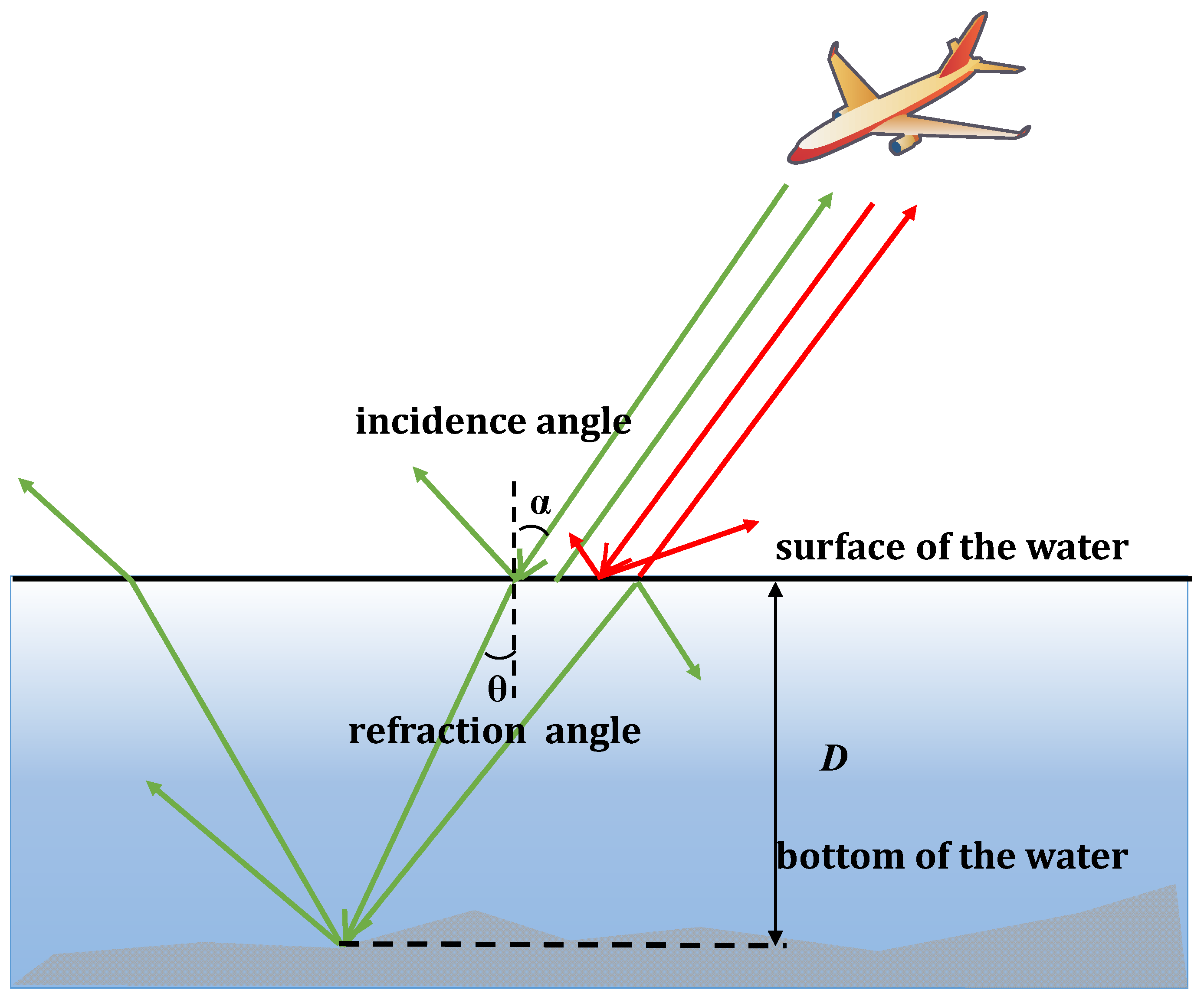
2.1. Principle of ALB

Airborne LiDAR bathymetry is an active remote sensing bathymetry technology that is based on the propagation characteristics of light in water; additionally, the attenuation of blue–green light at 470–580 nm in water is relatively low [1,2]. Thus, the technology generally uses a blue–green laser with a wavelength of 532 nm. The dual-frequency ALB system is usually implemented with low-power wide-beam pulses (1064 nm infrared laser) to detect the water surface and high-power narrow-beam pulses (532 nm blue–green laser) to detect the bottom [5]. Finally, the coordinates of the seafloor points are calculated by the propagation time of the laser underwater, the laser incidence angle, the refractive index of water, and other factors. The principle of dual-frequency ALB is shown in Figure 1.
The water depth calculation formula can be expressed as follows:
D = c Δ t 2 n w cos θ
where D is the water depth, Δt is the propagation time of the laser pulse in water, c is the propagation speed of the laser pulse in the lower atmosphere, θ is the refraction angle and can be derived from the laser incidence angle and the refractive index of water, and nw is the refractive index of water and varies with the conditions of the water environment (such as salinity, temperature, pressure, depth, and wavelength).

2.2. Refractive Index of Water

In the process of penetrating water, refraction occurs due to the difference in density between air and water. The refractive index of water is defined as the ratio of the propagation speed of light waves in a vacuum to that in water. This not only influences the propagation speed of the laser pulse underwater but also changes the propagation direction of the laser pulse in water.
According to Snell’s law, the refraction of a laser pulse from air to water can be expressed as follows:
sin α sin θ = n w n a = c c w
where α is the laser incidence angle, na is the refractive index of air, the air is usually considered under vacuum, and cw is the propagation speed of the laser pulse in water.
Since the refractive index of water is related to the wavelength of light, temperature, and pressure, the refractive index of water varies with these factors. The refractive index of water in an actual field measurement process is difficult to accurately measure; thus, the empirical formula of the refractive index calculation is usually used to obtain the refractive index of water. The empirical formula [12] for calculating the refractive index can be expressed as follows:
n w = 1.338 + 4 × 10 5 ( 486 λ + 0.003 D + 50 S T )
where λ is the wavelength of the laser (nm), S is the water salinity (%), and T is the water temperature (°C). Due to the presence of dissolved salts, organic matter, and other solutes in seawater, its refractive index is slightly greater than that of freshwater.

2.3. Influence of Refractive Index Changes on the ALB Error

The ALB errors due to refractive index changes in water are analyzed based on the propagation path of the bathymetry laser pulse and Snell’s law.

2.3.1. ALB Error Caused by Refractive Index Changes at the Water–Air Interface

When a laser pulse enters the water through the water–air interface, its propagation path changes due to water surface refraction. The range of the refractive index variation in shallow water areas is relatively small and is usually considered a fixed value, as shown in Figure 2. According to Snell’s law, the bathymetric error caused by refractive index changes at the water–air interface can be calculated as follows:
D 1 = c Δ t 2 n w cos ( arcsin ( sin α n w ) )
D 2 = c Δ t 2 n w cos ( arcsin ( sin α n w ) )
Δ D 1 = D 2 D 1 = c Δ t 2 ( 1 n w cos ( arcsin ( sin α n w ) ) 1 n w cos ( arcsin ( sin α n w ) ) )
where nw is the refractive index of water used in calculating the water depth, D1 represents the water depth when the refractive index of water is nw, D2 represents the water depth when the refractive index of water is nw, and ΔD1 is the bathymetric error caused by refractive index changes at the water–air interface.
The planimetric error caused by refractive index changes at the water–air interface can be calculated as follows:
P 1 = c Δ t 2 n w sin ( arcsin ( sin α n w ) )
P 2 = c Δ t 2 n w sin ( arcsin ( sin α n w ) )
Δ P 1 = P 2 P 1 = c Δ t 2 ( 1 n w sin ( arcsin ( sin α n w ) ) 1 n w sin ( arcsin ( sin α n w ) ) )
where P1 represents the horizontal displacement when the refractive index of water is nw, P2 represents the horizontal displacement when the refractive index of water is nw, and ΔP1 is the planimetric error caused by refractive index changes at the water–air interface.

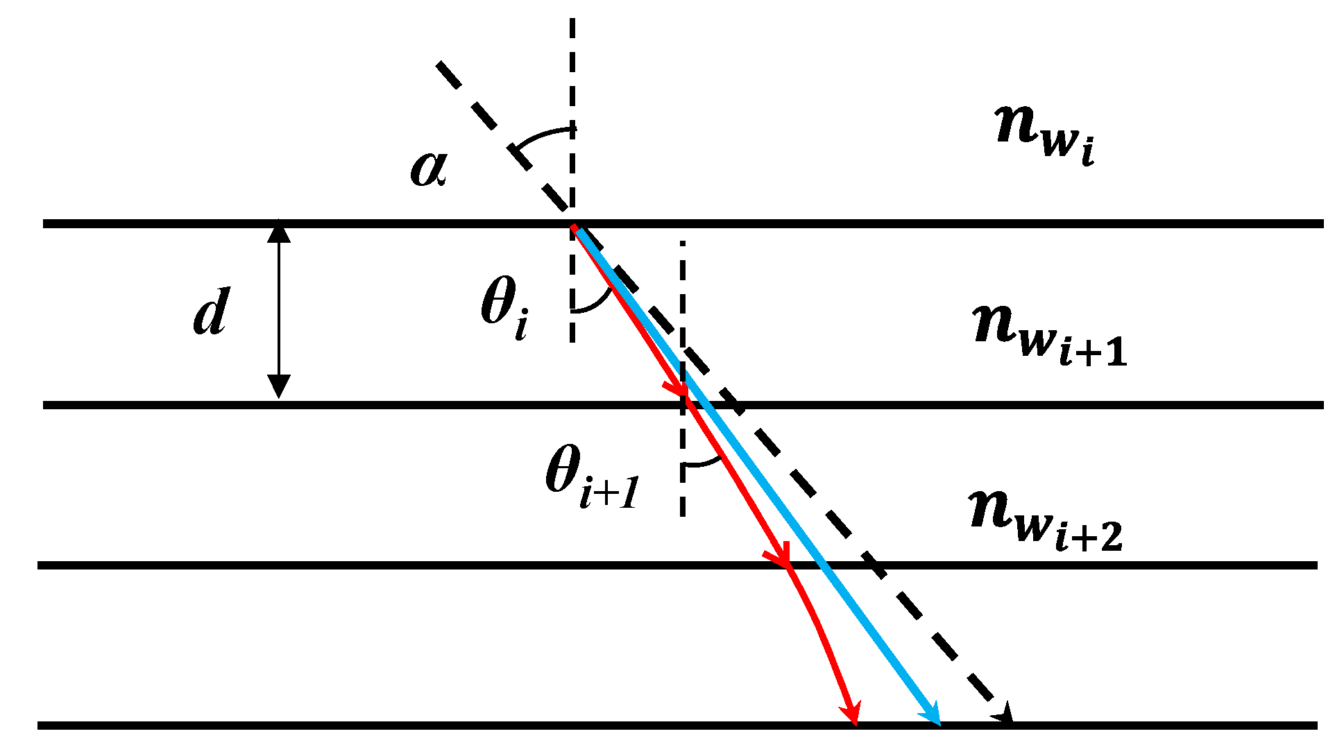
2.3.2. ALB Error Caused by Refractive Index Changes in the Water Column

Due to differences in the temperature, salinity, and pressure of water at different depths, the refractive index of water gradually increases with depth [19,20,21]. As shown in Figure 3, the propagation path of a laser pulse into water is not a straight line. The direction of travel will change with different refractive indices, and the refraction angle will also change; thus, analyzing the influence of refractive index changes in water on the ALB errors is equally important [22,23,24]. First, based on the principle that the propagation time T of the laser pulse in water remains fixed, the water depth is divided into layers with equal depth d, assuming that the refractive indices of the water in each layer are the same. Moreover, the propagation time of the laser pulse in each layer with a different refractive index is calculated. Then, the water depth and horizontal displacement are calculated when the calculated refractive index changes by using the total time T. Therefore, the bathymetric error is the difference between this water depth and the fixed water depth, and the planimetric error is the difference between this horizontal displacement and the fixed horizontal displacement.
The bathymetric error caused by refractive index changes in the layered water column is expressed by the following formula:
{ Δ t i + 1 = 2 d c n w i + 1 cos ( arcsin ( n w i sin α n w i + 1 ) ) D 3 = d ( M 1 ) + c 2 n w M ( T i = 1 M 1 t i ) cos ( arcsin ( n w M 1 sin α n w M ) )
Δ D 2 = D 3 D t
where T is the propagation time of the laser pulse underwater and is a fixed value, nwi (i = 0, 1, 2,… M) is the refractive index of the water column for each layer, nw0 denotes the refractive index of air, Δti is the propagation time of the laser pulse through each layer d, M is the number of layers when the water depth is layered by d, D3 is the water depth at which the laser pulse propagates when the water column is layered, Dt represents the fixed water depth, and ΔD2 is the bathymetric error caused by the refractive index changes in the layered water column.
The planimetric error caused by the refractive index changes in the layered water column is expressed by the following formula:
P 3 = i = 0 M 1 c Δ t i 2 n w i sin ( arcsin ( n w i sin α n w i + 1 ) ) + c 2 n w M ( T i = 0 M 1 t i ) sin ( arcsin ( n w M 1 sin α n w M ) )
Δ P 2 = P 3 P t
where P3 is the horizontal displacement of the propagation of the laser pulse when the water column is layered; Pt represents the fixed horizontal displacement of the propagation of the laser pulse in the water column and is calculated by the propagation time of the laser pulse in each layer, which consists of the total time T, the refraction angle, and the propagation speed of the laser pulse in each layer; and ΔP2 is the planimetric error caused by the refractive index changes in the layered water column.

3. Experiment and Analysis

To verify the influence of refractive index changes on the ALB errors, experiments and analyses were performed considering two aspects: the refractive index changes in water and the ALB errors caused by the refractive index changes.

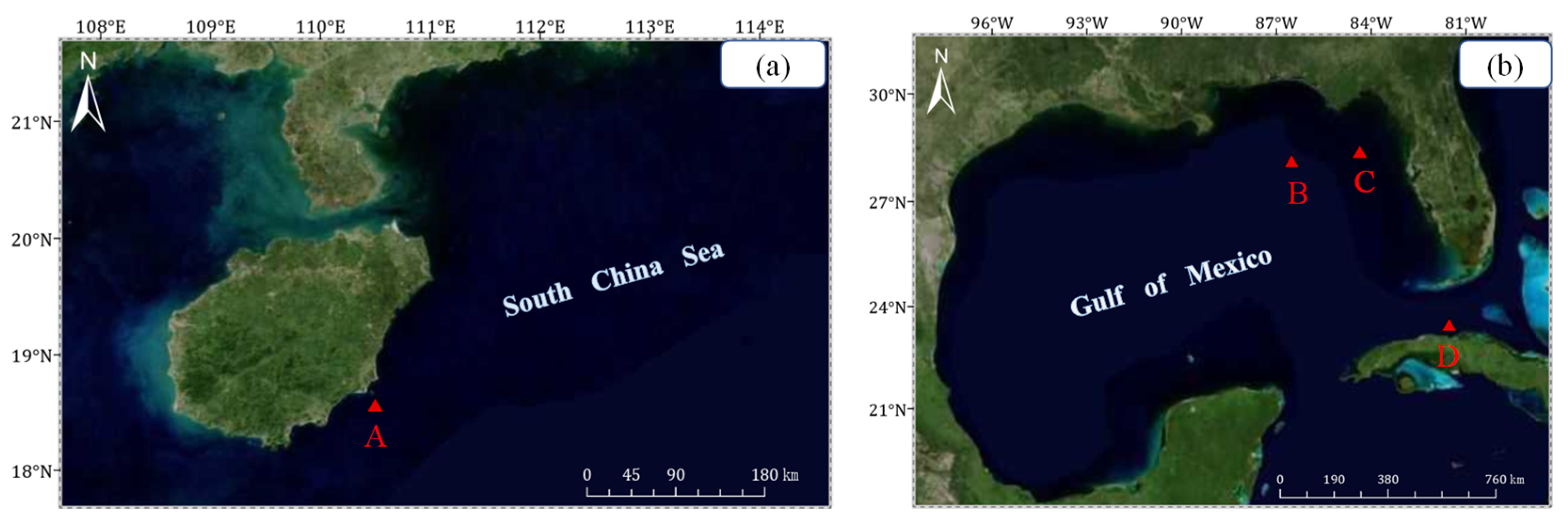
3.1. Experimental Area and Dataset

To analyze the influence of refractive index changes on ALB errors, the conductivity, temperature, and depth (CTD) data used in the experiment were obtained from measurements in the South China Sea and a database published on the website of the National Oceanic and Atmospheric Administration (NOAA) of the United States (Figure 4). The CTD data mostly included temperature, salinity, depth, pressure, and conductivity of water, among which conductivity and pressure are usually converted into salinity and depth [25]. In Figure 4, point A indicates the sampling site located in the South China Sea, and points B, C, and D indicate the sampling sites located in the Gulf of Mexico. The water quality in the South China Sea is favorable, which is more suitable for obtaining ALB data. The CTD data collection time at point A was 21 May 2022, during the southwest monsoon period with relatively weak winds. The Gulf of Mexico is in the tropics and subtropics and experiences high temperatures and frequent rainfall throughout the year. The CTD data at Point B were collected on 20 August 2010, which was during the season with the highest temperature and a better sea state, and the CTD data at Points C and D were collected on 4 March 2010, and 9 March 2018, which were periods often characterized by northerly gales with lower temperatures and less precipitation.

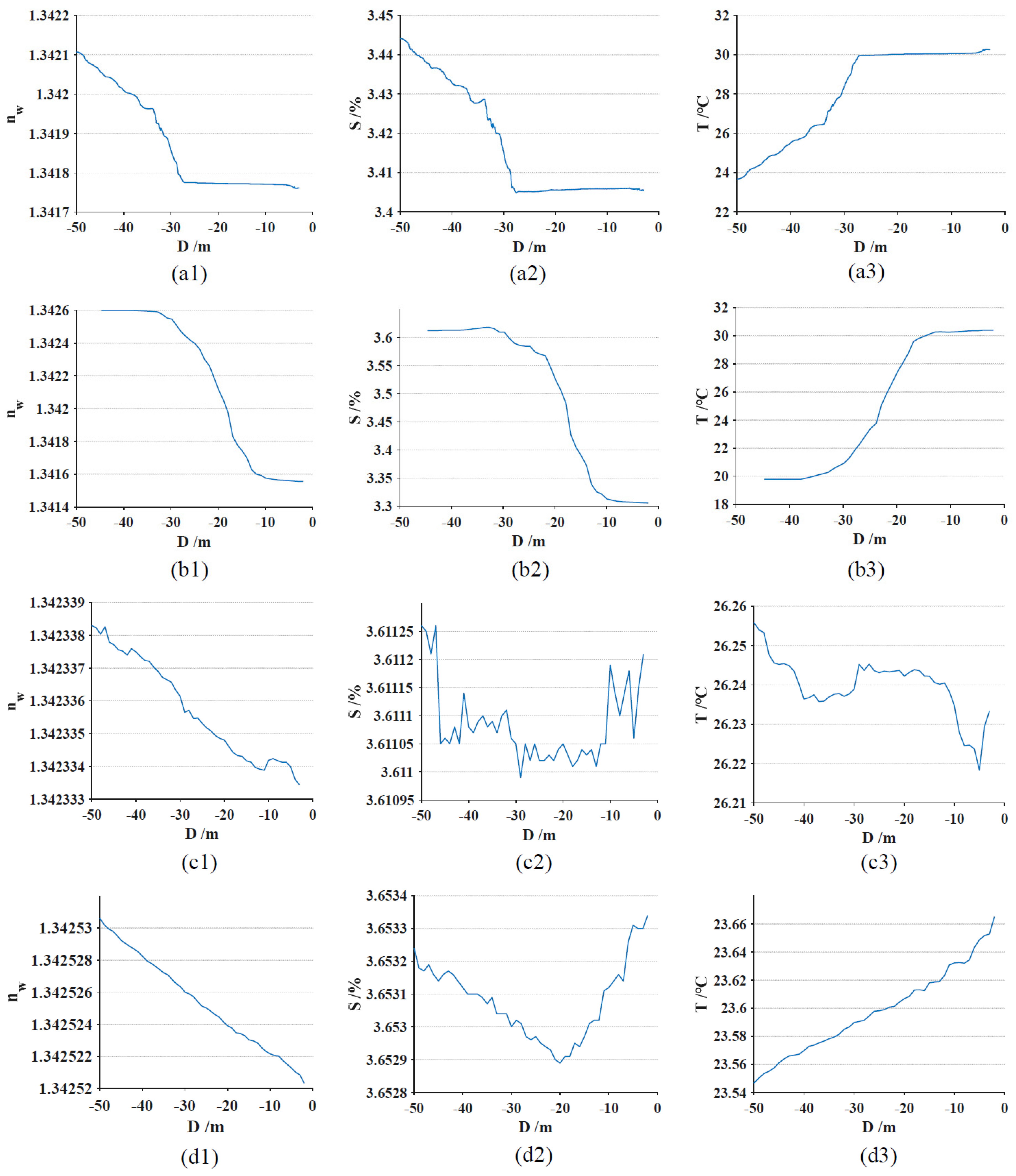
3.2. Analysis of the Refractive Index Changes in Water

The wavelength of the laser was set to 532 nm. According to the empirical Formula (3) for calculating the refractive index, the relationships between the depth (D) and refractive indices (nw), temperature (T), and salinity (S) of seawater could be obtained, as shown in Figure 5. Figure 5a–d correspond to sampling points A, B, C, and D, respectively. Figure 5a,b show that the salinity and refractive index of seawater increased with increasing depth, while the temperature had the opposite effect. Since sampling point A was collected in May with relatively weak winds, the temperature and salinity changed slightly from 0 to 28 m, resulting in small refractive index changes. According to (a2), (b2), (a3), and (b3), the salinity changes at sampling points A and B were less than 0.04% and 0.3%, respectively, and the temperature changes were less than 7 °C and 10 °C, respectively. The salinity changes at sampling points C and D were less than 0.00025% and 0.00045%, respectively, and the temperature changes were less than 0.035 °C and 0.1 °C, respectively. From the analysis of Figure 5a1–d1, the mean value of the refractive index of seawater where the sampling points were located was 1.342. Within a constant elevation of 50 m for a bathymetric floor, the refractive index changes in seawater at sampling points A and B were less than 0.001, and the refractive index changes in seawater at sampling points C and D were less than 0.0001. Due to differences in climate and season, factors such as wind speed, rainfall, and water solutes could lead to differences in the accuracy of the measurement data. The variation ranges of sampling points A and B were larger than those of sampling points C and D.
As shown in Figure 5, the relationships between changes in (c) and (d) were significantly different from those in (a) and (b) and were influenced by the oceanic mixed layer. The ocean mixed layer was generally within 100 m of the ocean surface, and heat exchange, momentum, and gases between the atmosphere and the interior of the ocean mainly occurred in the mixed layer. Due to the promotion of various processes, such as wind stirring, waves, and turbulence generated by convective mixing, the depth of the mixed layer will undergo seasonal changes, which usually result in large fluctuations in salinity and temperature [26,27,28,29,30]. The seasons in which sampling points C and D were located were often accompanied by northerly winds, and the warm current in the Gulf of Mexico is large and has a high velocity, which is driven by multiple factors that create unique climatic conditions. According to the above analysis, although there were fluctuations in the refractive index at sampling points C and D, the ranges of the temperature, salinity, and refractive index changes were smaller, and the range of refractive index changes was one order of magnitude smaller than that at points A and B.
Simulation experiments were also conducted to analyze the changes in refractive indices in seawater. We regarded one of the factors as the typical value and the other two as variables. The typical temperature, salinity, and depth of the seawater were set to 30 °C, 3.41%, and 50 m, respectively. The salinity ranged from 3% to 4%, and the depth ranged from 0 to 50 m when the temperature was 30 °C. The depth ranged from 0 to 50 m, and the temperature ranged from 10 °C to 40 °C when the salinity was 3.41%. The salinity ranged from 3% to 4%, and the temperature ranged from 10 °C to 40 °C when the depth was 50 m. Then, the refractive indices could be obtained under different conditions based on Formula (3). The results of the simulation experiments are shown in Figure 6. As shown in Figure 6, when the temperature was set to a certain value, the influence of salinity changes on the refractive index of seawater was more evident than that of depth changes. When the salinity was set to a certain value, the influence of temperature changes on the refractive index of seawater was more evident than that of depth changes. When the depth was set to a certain value, changes in the salinity and temperature both significantly influenced the refractive index of seawater. Regardless of whether simulated or measured data were used, the salinity, temperature, and depth of seawater minimally influenced the refractive indices of seawater within a constant elevation of 50 m for a bathymetric floor. Overall, the refractive indices of seawater were positively correlated with depth and salinity but negatively correlated with temperature. Specifically, the refractive index increased with depth and salinity and decreased with temperature. However, the corresponding influencing factors caused relatively small changes in the refractive indices of seawater.

3.3. Analysis of the ALB Error Caused by Refractive Index Changes

3.3.1. Analysis of the ALB Error Caused by Refractive Index Changes at the Water–Air Interface

As shown in Figure 5, the average calculated refractive index of the seawater at the four sampling points was 1.342. To study the effect of the ALB errors due to the refractive index changes at the water–air interface, the depths (D1) were set to 5 m, 10 m, 30 m, and 50 m, and the laser incidence angles of the emitted laser pulses were set to 5°, 10°, 15°, and 20°, and the refractive index changes were in the range of 1.333–1.353. After that, the bathymetric error in Figure 7 can be obtained by substituting these parameters into Formulas (4)–(6). Similarly, the planimetric error in Figure 8 can be obtained by substituting these parameters into Formulas (7)–(9).
As shown in Figure 7, a linear relationship was obtained between the bathymetric error and the refractive index of water. When the laser incidence angle was 15°, for every 0.001 change in the refractive index of water, the bathymetric error changed by 0.004 m, 0.007 m, 0.020 m, and 0.036 m for water depths of 5 m, 10 m, 30 m, and 50 m, respectively (Figure 7a,b). As shown in Figure 8a,b, for every 0.001 change in the refractive index of water, the planimetric error changed by 0.001 m, 0.003 m, 0.008 m, and 0.015 m for water depths of 5 m, 10 m, 30 m, and 50 m, respectively. Because the refractive index was influenced by temperature and salinity, where the temperature and salinity changes were small when they were affected by the water surface temperature and environment, the refractive index also changed slightly. Therefore, when the refractive index was not influenced by the surface temperature or environment in water, the bathymetric errors and planimetric errors caused by the refractive index changes increased with increasing depth.
The refractive index changes in shallow-water areas were less than 0.001 based on Figure 5 and Figure 6, resulting in maximum bathymetric errors and planimetric errors less than 0.036 m and 0.015 m, respectively. Additionally, as shown in Figure 7 and Figure 8, when the refractive index of water was less than the average calculated refractive index, the water depth was deeper and horizontal displacement was greater; conversely, the water depth was shallower and horizontal displacement was small. Therefore, if the refractive index of water was set to 1.333, the error was greater than that at 1.342.
To analyze the influence of the laser incidence angle on the ALB errors, a water depth of 50 m was selected as a fixed value, and the results are shown in Figure 7c,d, and Figure 8c,d. The bathymetric error decreased with increasing laser incidence angle, while the change in the planimetric error was the opposite. The influence of the incidence angle changes on the bathymetric error was relatively small when the refractive indices of the water columns were the same, and this occurred only at the millimeter scale. However, the incidence angle change had a greater influence on the planimetric error than on the bathymetric error. When the refractive index was 1.333, the planimetric error changed by 0.045 m for every 5° increase in incidence angle.

3.3.2. Analysis of the ALB Error Caused by Refractive Index Changes in the Water Column

To analyze the influence of the refractive index changes in the seawater column on the ALB error, the incidence angles were set to 5°, 15°, 10°, and 20°, and a seawater depth of 50 m was layered according to 0.5 m, 2 m, 5 m, 10 m, and 50 m. The duration of the laser pulse propagation underwater was used as a fixed value when the seawater column was layered to 0.5 m. After that, the bathymetric error and the planimetric error in Figure 9a,b can be calculated by substituting these parameters and the refractive index of sampling point A into Formulas (10) and (11) and Formulas (12) and (13), respectively. Similarly, the bathymetric error and the planimetric error in Figure 10a,b can be calculated by substituting these parameters and the refractive index of sampling point B into Formulas (10) and (11) and Formulas (12) and (13), respectively. The ALB errors generated under different conditions were obtained based on the refractive index changes at sampling points A and B, as shown in Figure 9 and Figure 10. For sampling point A, the bathymetric error and planimetric error increased with the layer depth of the seawater column and incidence angle. However, for sampling point B, the error initially decreased and then increased. For scenarios where the refractive index was not positively proportional to the water depth, the refractive index curve determined the mean value of the refractive index in each layer; this influenced the propagation speed and direction of the laser pulses. According to Formula (10), the propagation time of the laser pulse in each layer was influenced by the refractive index of the previous layer. The irregular variation in the refractive index curve may result in a variable relationship between the deviation of the layered and nonlayered measurements. Therefore, we simulated a scenario where the refractive index was positively proportional to the water depth, and the results are shown in Figure 11. Figure 11c shows that the simulated refractive index changed in a straight line; thus, both the bathymetric error and planimetric error increased with the layer depth of the seawater column, as shown in Figure 11a,b. However, due to the small change in the refractive index, the ALB error was also low and could be disregarded.

4. Conclusions

To systematically analyze the influences of refractive index changes in water on the ALB error, the relationships between the refractive indices of water and the depth, salinity, and temperature were analyzed using measured CTD data and simulated data. Then, based on Snell’s Law, the influence of refractive index changes on the ALB error was analyzed in terms of the refractive index of the water–air surface and the refractive index in the water column. Based on the results from the measurements and simulation experiments, the following conclusions are drawn within a constant elevation of 50 m for a bathymetric floor:
(1)
Based on the empirical formula for refractive index calculations, the refractive index changes in water caused by temperature, salinity, and depth were less than 0.001, and the average calculated refractive index of seawater at the sampling points was 1.342;
(2)
In a water environment, the ALB error caused by changes in the refractive index of the water–air interface increases with depth. The maximum bathymetric error and maximum planimetric error caused by a change in the refractive index of 0.001 were 0.036 m and 0.015 m, respectively. The bathymetric error decreased with increasing laser incidence angle, while the planimetric error showed the opposite behavior. The influence of incidence angle changes on bathymetric error was relatively low when the refractive indices of the water columns are the same and are only at the millimeter level. However, the incidence angle changes have a greater influence on the planimetric error than on the bathymetric error. When the refractive index was 1.333, the planimetric error changed by 0.045 m for every 5° increase in the incidence angle. Thus, it is necessary to determine whether the effect of the ALB error due to refractive index changes in water needs to be corrected based on the accuracy requirements of data acquisition;
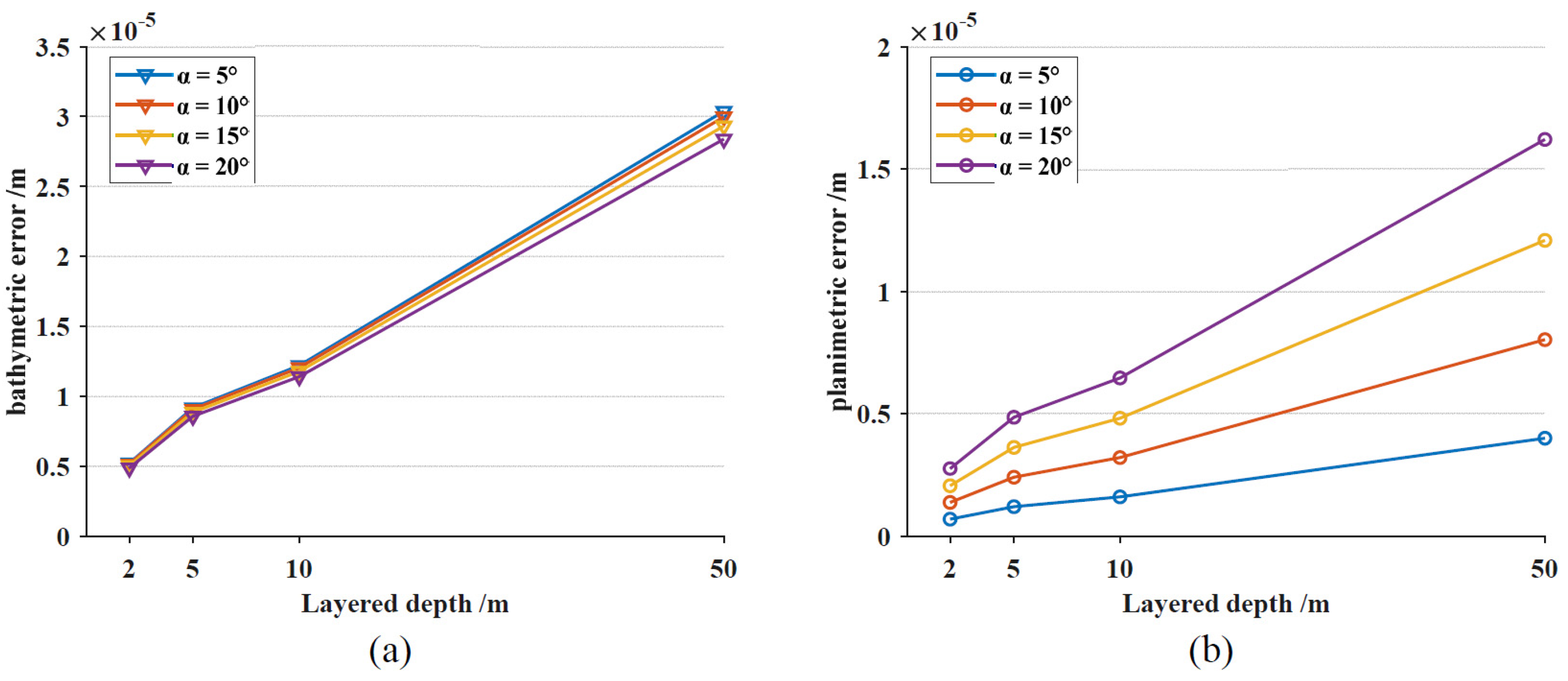
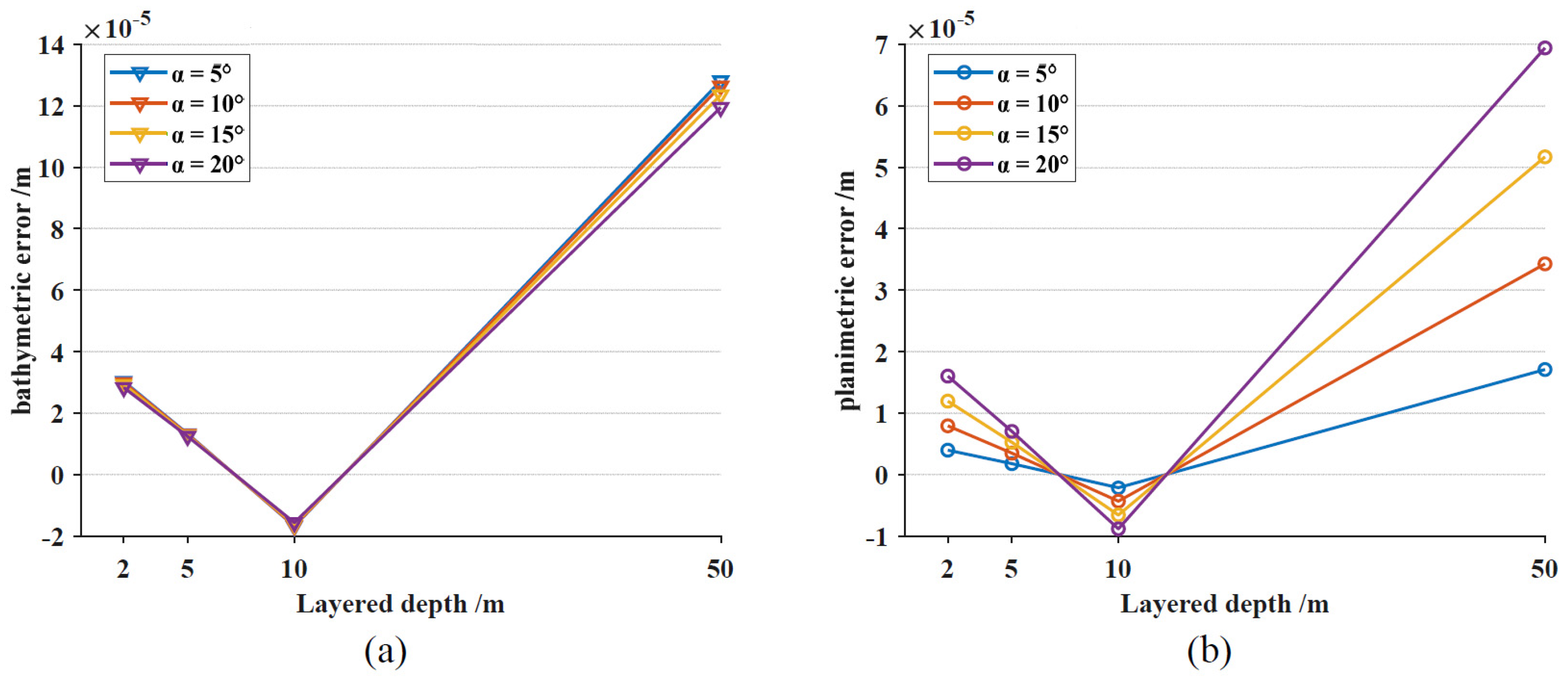
(3)
The ALB errors caused by refractive index changes in the water column were relatively low due to small changes in the refractive indices. The bathymetric error and planimetric error usually increase with increasing layer depth and incidence angle under the conditions of the calculated refractive index. However, due to the influence of the refractive index, irregular variations in bathymetry and planimetric errors may occur. The difference between the water depth calculated by the average refractive index without layers and the water depth calculated by the refractive index with layers was not significant and can be disregarded for different layers and incidence angles;
(4)
The premise of this study is that the refractive index of each horizontal layer is stable and constant during ALB pulse propagation and the difference in the refractive indices at different locations within the survey areas is small. Relevant corrections can be considered in the areas of underwater structural monitoring of equipment such as cables and turbines in offshore wind power, underwater archaeological surveys, underwater environmental monitoring, and precision assessment of spaceborne marine remote sensing data.

Author Contributions

Conceptualization, X.X., Z.J., W.X., Y.G., Y.L. and Z.G.; methodology, Z.J., W.X. and Y.G.; validation, Y.L. and Z.G.; formal analysis, Z.J., W.X. and Y.G.; data curation, Z.J. and Y.G.; writing—review and editing, X.X. and Z.J.; visualization, Z.J.; supervision, W.X. and Y.G.; project administration, Y.L.; funding acquisition, X.X., W.X. and Z.G. All authors have read and agreed to the published version of the manuscript.

Funding

This research was funded by the National Natural Science Foundation of China (41871381, 42171292, 41401573 and 42271273).

Institutional Review Board Statement

Not applicable.

Informed Consent Statement

All authors have read and agreed to the published version of the manuscript.

Data Availability Statement

The data presented in this study are available upon request from the corresponding author. The data are not publicly available due to privacy restrictions.

Acknowledgments

We would like to thank the National Oceanic and Atmospheric Administration (NOAA) of the United States for providing their datasets.

Conflicts of Interest

The authors declare no conflicts of interest.

References

  1. Xu, W.X.; Guo, K.; Liu, Y.X.; Tian, Z.W.; Tang, Q.H.; Dong, Z.; Li, J. Refraction error correction of Airborne LiDAR Bathymetry data considering sea surface waves. Int. J. Appl. Earth Obs. Geoinf. 2021, 102, 102402. [Google Scholar] [CrossRef]
  2. Guo, Y.D.; Feng, C.K.; Xu, W.X.; Liu, Y.X.; Su, D.P.; Qi, C.; Dong, Z.P. Water-land classification for single-wavelength airborne LiDAR bathymetry based on waveform feature statistics and point cloud neighborhood analysis. Int. J. Appl. Earth Obs. Geoinf. 2023, 118, 103268. [Google Scholar] [CrossRef]
  3. Guo, K.; Xu, W.X.; Liu, Y.X.; He, X.F.; Tian, Z.W. Gaussian half-wavelength progressive decomposition method for waveform processing of airborne laser bathymetry. Remote Sens. 2017, 10, 35. [Google Scholar] [CrossRef]
  4. Ji, X.; Tang, Q.H.; Xu, W.X.; Li, J. Island feature classification for single-wavelength airborne lidar bathymetry based on full-waveform parameters. Appl. Opt. 2021, 60, 3055–3061. [Google Scholar] [CrossRef]
  5. Xu, W.X.; Zhang, F.; Jiang, T.; Feng, Y.K.; Liu, Y.X.; Dong, Z.P.; Tang, Q.H. Feature curve-based registration for airborne LiDAR bathymetry point clouds. Int. J. Appl. Earth Obs. Geoinf. 2022, 112, 102883. [Google Scholar] [CrossRef]
  6. Tulldahl, H.M.; Philipson, P.; Kautsky, H.; Wikstrom, S.A. Sea floor classification with satellite data and airborne LiDAR bathymetry. Ocean Sens. Monit. V. 2013, 8724, 100–115. [Google Scholar]
  7. Birkebak, M.; Eren, F.; Pe’eri, S.; Weston, N. The effect of surface waves on airborne lidar bathymetry (ALB) measurement uncertainties. Remote Sens. 2018, 10, 453. [Google Scholar] [CrossRef]
  8. Zhao, J.H.; Zhao, X.L.; Zhang, H.M.; Zhou, F.N. Improved model for depth bias correction in airborne LiDAR bathymetry systems. Remote Sens. 2017, 9, 710. [Google Scholar] [CrossRef]
  9. Su, D.P.; Yang, F.L.; Ma, Y.; Wang, X.K.; Yang, A.X.; Qi, C. Propagated uncertainty models arising from device, environment, and target for a small laser spot airborne LiDAR bathymetry and its verification in the South China Sea. IEEE Trans. Geosci. Remote Sens. 2019, 58, 3213–3231. [Google Scholar] [CrossRef]
  10. Hodgson, M.E.; Bresnahan, P. Accuracy of airborne lidar-derived elevation. Photogramm. Eng. Remote Sens. 2004, 70, 331–339. [Google Scholar] [CrossRef]
  11. Parrish, C.E.; Magruder, L.A.; Neuenschwander, A.L.; Forfinski-Sarkozi, N.; Alonzo, M.; Jasinski, M. Validation of ICESat-2 ATLAS bathymetry and analysis of ATLAS’s bathymetric mapping performance. Remote Sens. 2019, 11, 1634. [Google Scholar] [CrossRef]
  12. Westfeld, P.; Maas, H.G.; Richter, K.; Weiß, R. Analysis and correction of ocean wave pattern induced systematic coordinate errors in airborne LiDAR bathymetry. ISPRS J. Photogramm. Remote Sens. 2017, 128, 314–325. [Google Scholar] [CrossRef]
  13. Yang, F.L.; Su, D.P.; Ma, Y.; Feng, C.K.; Yang, A.X.; Wang, M.W. Refraction correction of airborne LiDAR bathymetry based on sea surface profile and ray tracing. IEEE Trans. Geosci. Remote Sens. 2017, 55, 6141–6149. [Google Scholar] [CrossRef]
  14. Maas, H.G. On the accuracy potential in underwater/multimedia photogrammetry. Sensors 2015, 15, 18140–18152. [Google Scholar] [CrossRef] [PubMed]
  15. Tilton, L.W.; Taylor, J.K. Refractive index and dispersion of distilled water for visible radiation, at temperatures 0 to 60 C. J. Res. Natl. Bur. Stand. 1938, 20, 419–447. [Google Scholar] [CrossRef]
  16. Quan, X.H.; Edward, S.F. Empirical equation for the index of refraction of seawater. Appl. Opt. 1995, 34, 3477–3480. [Google Scholar] [CrossRef]
  17. Schwarz, R.; Pfeifer, N.; Pfennigbauer, M.; Mandlburger, G. Depth measurement bias in pulsed airborne laser hydrography induced by chromatic dispersion. IEEE Geosci. Remote Sens. Lett. 2020, 18, 1332–1336. [Google Scholar] [CrossRef]
  18. Ranndal, H.; Christiansen, P.S.; Kliving, P.; Andersen, O.B.; Nielsen, K. Evaluation of a statistical approach for extracting shallow water bathymetry signals from ICESat-2 ATL03 photon data. Remote Sens. 2021, 13, 3548. [Google Scholar] [CrossRef]
  19. Stanley, E.M. The refractive index of seawater as a function of temperature, pressure and two wavelengths. Deep Sea Rese. Oceanogr. Abstr. 1971, 18, 833–840. [Google Scholar] [CrossRef]
  20. McNeil, G.T. Metrical fundamentals of underwater lens system. Opt. Eng. 1977, 16, 128–139. [Google Scholar] [CrossRef]
  21. Mahrt, K.H.; Waldmann, H.; Kroebel, W. A newly developed in situ-measuring oceanographical probe sensing the optical index of refraction of sea water with new aspects of salinity and density determinations. In Proceedings of the OCEANS 82, Washington, DC, USA, 20–22 September 1982; IEEE: Piscataway, NJ, USA, 1982; pp. 266–271. [Google Scholar]
  22. Millard, R.C.; Seaver, G. An index of refraction algorithm for seawater over temperature, pressure, salinity, density, and wavelength. Deep Sea Research Part A. Oceanogr. Res. Pap. 1990, 37, 1909–1926. [Google Scholar]
  23. Zhao, X.Y.; Peng, Y.F.; Zhai, C.C.; Han, X.Y.; Zhang, Y. Influence of inorganic salts on the refraction index of water. Appl. Mech. Materials. 2015, 716, 118–121. [Google Scholar] [CrossRef]
  24. Saputra, L.R.; Radjawane, I.M.; Park, H.; Gularso, H. Effect of Turbidity, Temperature and Salinity of Waters on Depth Data from Airborne LiDAR Bathymetry. In IOP Conference Series: Earth and Environmental Science; IOP Publishing: Bristol, UK, 2021; Volume 925, p. 012056. [Google Scholar]
  25. Gu, L.J.; He, X.G.; Zhang, M.; Lu, H.L. Advances in the Technologies for Marine Salinity Measurement. J. Mar. Sci. Eng. 2022, 10, 2024. [Google Scholar] [CrossRef]
  26. Kraus, E.B.; Turner, J.S. A one-dimensional model of the seasonal thermocline II. The general theory and its consequences. Tellus 1967, 19, 98–106. [Google Scholar] [CrossRef]
  27. Huang, P.Q.; Lu, Y.Z.; Zhou, S.Q. An objective method for determining ocean mixed layer depth with applications to WOCE data. J. Atmos. Ocean. Technol. 2018, 35, 441–458. [Google Scholar] [CrossRef]
  28. Chen, Y.; Xiao, C.B.; Zhang, Y.; Lai, Z.G. The Mixed Layer Salinity Budget in the Northern South China Sea: A Modeling Study. J. Mar. Sci. Eng. 2023, 11, 1693. [Google Scholar] [CrossRef]
  29. Johnson, G.C.; Lyman, J.M. GOSML: A global ocean surface mixed layer statistical monthly climatology: Means, percentiles, skewness, and kurtosis. J. Geophys. Res. Ocean. 2022, 127, e2021JC018219. [Google Scholar] [CrossRef]
  30. Brenner, S.; Thomson, J.; Rainville, L.; Torres, D.; Doble, M.; Wilkinson, J.; Lee, C. Acoustic sensing of ocean mixed layer depth and temperature from uplooking ADCPs. J. Atmos. Ocean. Technol. 2023, 40, 53–64. [Google Scholar] [CrossRef]
Figure 1. Principle schematic of dual-frequency ALB.
Jmse 12 00435 g001
Figure 2. Diagram of the ALB error caused by the influence of the refractive index at the water–air interface.
Jmse 12 00435 g002
Figure 3. Diagram of layered water refraction propagated by laser pulses.
Jmse 12 00435 g003
Figure 4. Distribution of the CTD data sampling points. (a) Location of the sampling point A in the South China Sea; (b) Locations of the sampling points B, C and D in the Gulf of Mexico.
Jmse 12 00435 g004
Figure 5. The calculated refractive index and measured temperature and salinity as a function of seawater depth. (a1d1) Relationships of the refractive indices with water depth at sampling points A, B, C, and D, respectively; (a2d2) Relationships of seawater salinity with water depth at sampling points A, B, C, and D, respectively; (a3d3) Relationships of seawater temperature with water depth at sampling points A, B, C, and D, respectively.
Jmse 12 00435 g005
Figure 6. Diagrams of the changes in the refractive indices with depth, temperature, and salinity of seawater. (a) Refractive indices with seawater depth and salinity; (b) Refractive indices with seawater depth and temperature; (c) Refractive indices with seawater salinity and temperature.
Jmse 12 00435 g006
Figure 7. Relationships between bathymetric error and the refractive index of water. (a,b) Bathymetric errors caused by different water depths when the incidence angle is 15°. (c,d) Bathymetric errors caused by different incidence angles when the water depth is 50 m.
Jmse 12 00435 g007
Figure 8. Relationships between the planimetric error and the refractive index of water. (a,b) Planimetric errors caused by the different water depths when the incidence angle is 15°; (c,d) Planimetric errors caused by the different incidence angles when the water depth is 50 m.
Jmse 12 00435 g008
Figure 9. Changes in the ALB error with the layer depth of the seawater column at sampling point A. (a) Bathymetric error; (b) planimetric error.
Jmse 12 00435 g009
Figure 10. Changes in the ALB error with layer depth in the seawater column at sampling point B. (a) Bathymetric error; (b) planimetric error.
Jmse 12 00435 g010
Figure 11. Changes in the ALB error of the simulated data with the layer depth of seawater. (a) Bathymetric error; (b) planimetric error; (c) simulated refractive index of the seawater column.
Jmse 12 00435 g011
Disclaimer/Publisher’s Note: The statements, opinions and data contained in all publications are solely those of the individual author(s) and contributor(s) and not of MDPI and/or the editor(s). MDPI and/or the editor(s) disclaim responsibility for any injury to people or property resulting from any ideas, methods, instructions or products referred to in the content.

