Article

The Potential of Tidal Energy Production in a Narrow Channel: The Gulf of Morbihan

1
LUSAC EA 4253, University of Caen Normandy, 60 rue Max-Pol Fouchet, F-50130 Cherbourg en Cotentin, France
2
Geo-Ocean, Univ Bretagne Sud, Univ Brest, CNRS, Ifremer, UMR6538, F-56000 Vannes, France
*
Author to whom correspondence should be addressed.
J. Mar. Sci. Eng. 2024, 12(3), 479; https://doi.org/10.3390/jmse12030479
Submission received: 5 February 2024 / Revised: 8 March 2024 / Accepted: 8 March 2024 / Published: 12 March 2024

Abstract

:
The tidal currents of the Gulf of Morbihan reach up to 3.5 m/s within a narrow (200 m large) channel connecting the sea to the inner part of the gulf. In this study, a Telemac2D model validated with a large dataset of field measurements is used to assess the resources of the gulf. The results show that two sites have the potential to host up to 48 turbines (diameter of 8 m). If the entire width of the channel is occupied by turbines, significant increases in current speed are expected to occur on each side of the main channel. Simulations also show that flow changes differ between ebbing and flooding tides. During ebbing tide, the changes are limited in amplitude and remain localised within the channel. During flooding tide, the changes are more significant, especially in the vicinity of one of the two sites where the water passing through the site is flushed into a large and shallow basin. In this area, energy extraction significantly modifies the spatial distribution of the current velocities. We consider different scenarios of tidal energy extraction. The results show that flow perturbation can be significantly reduced using a lower density of turbines, that extracting tidal energy at one site slightly reduces the resource of the other, and that the deployment of two turbines (testing conditions) has a negligible effect on ambient current speeds.

1. Introduction

The exploitation of tidal stream energy is currently undergoing rapid development, with several technologies being successfully tested on-site and several commercial farm projects under study. Across the world, several sites have the potential to harvest hundreds of MW, such as the Alderney Race, between France and the UK [1]; the Pentland firth, UK [2]; the Bay of Fundy, Canada [3]; the Fromveur Strait, France [4]; etc. Those sites are large (cross-sections of several kilometres) and deep enough (depth greater than 30 m) to deploy dozens or hundreds of turbines with rotor diameters of around 15–25 m. Complementary to those large-scale projects, numerous scenarios of tidal stream exploitation relying on smaller-scale sites are also under development, in some instances to provide renewable electricity to remote coastal communities [5]. Examples of small-scale sites and projects can be found in estuaries, e.g., the Ria of Ferrol, Spain [6]; the Ria of Muros, Spain [7]; in narrow tidal channels such as the Puget Sound, the USA [8]; or between islands, such as the Faroe Islands [9] and the Flores and Andonara Islands, Indonesia [10]. An assessment of the resources at the latter (small-scale) sites demonstrates that tidal stream turbines can significantly contribute to the energy mix, which is the first prerequisite for project development. The second condition is that the exploitation of the tidal stream has a limited impact on the physical environment. To this end, it is necessary to determine the density and location of turbines that have a minimal impact on the environment.
The flow perturbation caused by tidal turbines has been assessed at numerous tidal stream energy sites, with most studies focusing on large-scale tidal projects (e.g., [3,11,12,13], etc.). Those studies showed that the impact of turbines strongly differs from one tidal energy project to another, not only because the tidal energy scenarios vary (in terms of number of turbines, turbine size, spacing between turbines, etc.) but also because the flow configurations are site-specific and differ depending on seabed morphology, depth, the lateral constriction of the flow, the blockage ratio (ratio between the area swept by blades and the cross-sectional area of the channel), etc. Hence, changes in velocity magnitude caused by tidal arrays vary in a wide range of values, from 0.05 m/s at sites with low tidal resources (e.g., [14]) to 3.5 m/s for large-scale projects, e.g., 120 turbines in the Pentland Firth [15]. Between these two bounds, perturbations of current velocity are more often of the order of 0.5–1 m/s, e.g., [13,16,17]. As it is not possible to transpose results from one study site to another, site-specific studies are required. In this article, we focus on a site with a particular morphology, namely, the Gulf of Morbihan.
The Gulf of Morbihan is a complex tidal system composed of bays, islands, and a network of tidal channels. This coastal system has characteristics midway between an estuary and a lagoon. At each tide, the gulf is filled and emptied, and the main channel, which is approximately 200 m large, comprises tidal currents that reach speeds of up to 3.5 m/s, especially in the “La Jument” tidal current. This site thus attracts the interest of tidal turbine developers, especially MH56, which plans to test two Sabella turbines. Their objective is twofold: producing renewable energy for the inhabitants of the gulf and testing two 8 m diameter devices that could be deployed at tidal energy sites with comparable flow characteristics. As is the case with all projects, the development of such a project needs to demonstrate that there are sufficient resources and that the turbines only have a limited impact on the environment. The latter constraint here is even more crucial because the Gulf of Morbihan is remarkably rich in terms of biodiversity and hosts several human activities, such as fishing, oyster farming, sailing, tourism, etc.
Very few studies have been conducted on the hydrodynamics of the Gulf of Morbihan. Thus, the first objective of this article was to characterise the hydrodynamics of the site and its tidal resource. The methodology relied on the combination of a bidimensional model (Telemac2D) and a large set of field measurements acquired with ADCP, pressure sensors, and tidal gauges. The model permitted the identification of two zones suited for harvesting tidal stream energy. The second objective of this article concerned the estimation of the flow perturbations induced by the turbines deployed at the two potential sites. The far-field effect of tidal energy harvesting was investigated by including turbines in the numerical model and by comparing the results to a reference simulation without turbines. We analysed how the specific morphology of the site impinges on the spatial distribution of the flow perturbations. Particular features of the site include the narrowness of the channel, the fact that two tidal stream energy sites are located along the same channel, and the fact that the channel opens out into a shallow basin. The investigations focused on the perturbations of current velocities (perturbation on water elevations have not been analysed), as this type of disturbance has the greatest influence on turbine output (e.g., [18]) and on the transport of natural material, such as dissolved nutriments and pollutants, particulate organic matter, and sediments [19,20,21].
The remainder of this paper is organised as follows. Our methods are described in Section 2. This section includes a description of the site, field measurements, a numerical model, and the way turbines are represented in the numerical model. Our results are presented in Section 3. This section includes a resource assessment of the site, an analysis of the flow perturbations induced by the turbines, and a discussion. Section 4 highlights the main conclusions of this study.

2. Materials and Methods

2.1. Site Description

The Gulf of Morbihan is located along the French Atlantic coast in South Brittany (Figure 1a). It represents a steep geographical depression that gives rise to a water body with a surface area of 11,500 hectares and a 250 km long shoreline. This water body connects to the sea via a narrow 900 m opening at Port Navalo. It has a complex morphology with dozens of islands constraining the propagation of the tide through a network of narrow channels (Figure 1b). Close to the entrance, the water currents can surge up to a velocity magnitude of 3.5 m/s during spring tides, which makes the site a potential location for tidal energy development. The tidal patterns within the gulf display substantial temporal and spatial variations. As the tide propagates into the gulf, its amplitude decreases; it measures around 5 m at the entrance of the gulf, dwindles to 4 m near Vannes, and diminishes and reaches 3 m near Ile Bailleron (Figure 1b). The gulf can be divided into three zones. The entrance is characterised by strong currents, coarse sediments, and uneven seabed morphology. The transition zone is marked by wide sandy–muddy channels. The easternmost sector is a sheltered zone characterised by small muddy channels. At the entrance of the gulf, the primary tidal channel spans approximately 200 m in width and reaches a depth of 25 m. Its cross-section has a U-shape with a flat and horizontal seabed and abrupt walls that overhang intertidal areas. During ebbing and flooding tides, a large volume of water transits through this main channel, generating high current speeds. These speeds reach 3.5 m/s during ebbing tides and can be 1.5 times greater than those experienced during flooding tides [22], particularly to the south of “Ile Longue” and “Ile of Berder” (Figure 1c). Eastwards this zone, the depth of the main channel progressively decreases. The channel enlarges and is split into two parts: one circumventing “Ile aux Moines” by the north and the other by the south (Figure 1c).

2.2. Field Data

Different sources of bathymetric data have been used (i) to build the computational domain and (ii) to map areas where turbines could be deployed based on the depth criterion. Outside the gulf, we used the digital elevation model of the SHOM (French navy), which has a spatial resolution of 0.001° (approximately 110 m). Inside the gulf, we used Litto3D data, which have a 5 m resolution. For the calibration and validation of the model, we used the data acquired by two bottom-fixed ADCPs deployed in 2014 at two locations that may have sufficient potential to host turbines, namely, the south of “Ile Longue” (label “A1” in Figure 1c) and the south of “Ile de Berder” (label “A2” in Figure 1c). We also used two other bottom-fixed ADCPs deployed in 2019 in less energetic areas, which were the shallowest: one in a bay (label “A3” in Figure 1b) and the other near the inlet (label “A4” in Figure 1b). Pressure sensors were deployed during one week, in 2019, at six different locations (labels “P1” to “P6” in Figure 1b). Those data were used to assess the ability of the model to predict water elevations, especially in the inner part of the gulf. Finally, the tidal gauge of “Le Crouesty” (label “TG” in Figure 1b) was used, permitted to assess model predictions of water elevation outside the gulf (near the inlet). Details of the field data are listed in Table 1.

2.3. Numerical Model

The hydrodynamic simulations of the gulf were performed with Telemac2D, which solves the shallow water equations (Equation (1)) with a finite element method [23]. The model was forced with 15 tidal constituents (M2, S2, N2, K2, K1, O1, P1, Q1, MM, MF, M4, MN4, MS4, 2N2, and S1) provided by the TPXO9.v4 database with a 1/6° resolution. The effects of the wind and waves were disregarded. The model was calibrated by adjusting the friction coefficient so that the model predictions fitted the current speeds measured by the bottom-fixed ADCP deployed in 2014 (“A1” and “A2” in Figure 1c).
h t + u . h + h   d i v u = 0 u t + u . u = g Z x + 1 h d i v h ν t u + S x v t + u . v = g Z y + 1 h d i v h ν t v + S y
where h is the water depth; u , v are the depth-averaged velocity components; g is the gravity acceleration; Z is the free surface elevation; ν t is the momentum diffusion coefficient; and S is the momentum sink term.
The spatial coverage of the domain was chosen according to the resolution of the TPXO database and the complexity of the shoreline. Different domain sizes have been tested and compared using data acquired at the entrance to the gulf (tidal gauge “TG”) as a reference (to check that tide propagation was well simulated outside the gulf). The unstructured mesh contained 109,188 nodes with cell sizes varying from 10 km at the model boundary to 15 m within the main channel. The choice of the smaller cell size (15 m) was critical, as it strongly influenced the model predictions within the main channel. Tests with varying cell sizes (7.5, 15, 25, and 50 m) but similar (50 m) resolution for the bathymetric data (same seabed morphology for all meshes) did not show significant differences. This suggested that the numerical discretisation had a small influence on the results. Tests with variable mesh resolutions (50, 25, 15, and 7.5 m) and variable resolutions in the bathymetric data (more detailed seabed morphology with finer meshes) showed that refining the mesh to 15 m improved the fit in line with the measurements. Those tests also showed that the results were comparable when using the two meshes with the finest resolutions (15 m and 7.5 m). Hence, we adopted 15 m as the minimum cell size. The time step was set to 1 s, which corresponded to a CFL number smaller than 0.3. Finally, although it did not show a significant effect on the model performance in comparison with simpler models (e.g., constant turbulent viscosity), turbulence closure relied on the k-ε model, which has proven its reliability in several comparable cases (e.g., [6,12,13]).
The validation of the model is described in Section 3.1.

2.4. Scenarios of Tidal Stream Exploitation

When the current speed upstream to a turbine is smaller than the rated velocity, the turbine output depends on the cubed current velocity magnitude, water density, area swept by the blade, and the (constant) power coefficient (Equation (2)). Hence, the most common proxy to screen tidal stream energy sites is power density (PD, Equation (3)), i.e., a proxy that depends only on the hydrodynamic characteristics of the flow and is independent of the turbine characteristics ( A , Cp, and U r a t e d ).
P = 1 2 ρ A C p U 3   i f   U < U r a t e d P = 1 2 ρ A C p U r a t e d 3 = P n o m   o t h e r w i s e
where ρ is the water density (which is assumed to be constant and equals 1025 kg/m3 here), A is the area swept by the blades, Cp is the power coefficient, U is the upstream velocity (unperturbed by the turbines), and Pnom is the nominal power delivered by the turbine when the velocity exceeds Urated.
P D ¯ = 1 2 ρ U 3 ¯
where the overbar stands for time–mean (over one year, as here).
The identification of the sites suited for the exploitation of tidal energy relied on two criteria: a minimum PD of 2.5 kW/m2 [24] and a minimum depth of 20 m to ensure a 6 m clearance above the turbines at low tide. The depth criterion relied on the characteristics of the Sabella turbine listed in Table 2 (rotor diameter of 8 m and hub height of 10 m). Once the zones satisfying both criteria were identified (we identified two zones), five different scenarios were considered. Scenario No. 1 corresponded to the maximum number of turbines. The latter was determined assuming a maximum turbine density of 579 turbines per km2. This density corresponded to different possible combinations of lateral and longitudinal spacings, such as 2.5D–10.8D, 3D–9D, or 3.5D–7.7D (these are standard spacings in comparable modelling works). Scenario No. 2 was more conservative and relied on turbine density that was twice as small. Scenarios with turbines deployed at one site at a time were also considered (scenarios Nos. 3 and 4). The comparison of the two latter scenarios (no interaction between sites) with reference scenario No. 1 (possible interactions between sites) permitted us to assess the influence of one site on the other, either in terms of resources or the cumulative perturbation of the flow field. Finally, a simulation with two turbines deployed south of “Ile Longue” was considered. This scenario corresponds to the tests scheduled by MH56.
In the numerical model, the effect of arrays of turbines was represented with the “enhanced friction” approach, which consisted of applying a momentum sink term ( S in Equation (1)) in the areas occupied by the tidal array(s). The sink term (Equation (4)) was computed from the turbines’ thrust (Equation (5)), assuming that upstream velocity is equal to local velocity (velocity within the farm). Such a methodology has been used in many studies to investigate the far-field effect of turbines on flow, such as in [12,25,26,27,28].
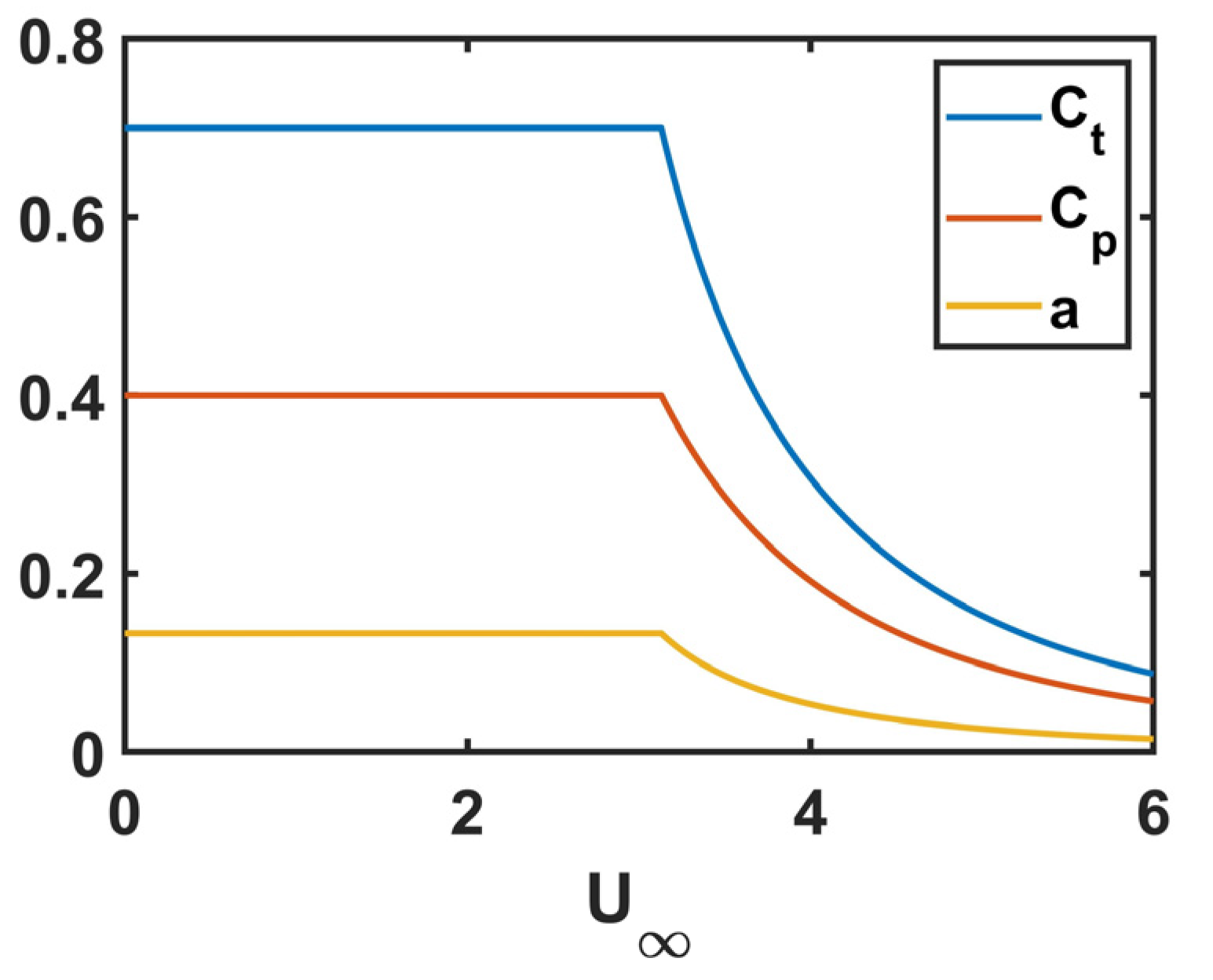
Most turbines are designed so that their output remains constant when the current magnitude exceeds the rated speed. In this range of current velocity, the power coefficient is reduced by a factor depending on the cubed current speed. In practice, this is achieved by modifying the turbine operation. According to actuator disk theory (Equations (6)–(8)), when the induction factor is smaller than 1/3, a reduction in the power coefficient is associated with a reduction in both the induction factor, a, and the thrust coefficient. This theory was used to obtain the evolution of thrust coefficients (hence the sink term introduced in the momentum equations) as a function of the flow velocity (Figure 2).
S = 1 2 n A C t U 2 h S f a r m
where n is the number of turbines, and S f a r m is the surface area covered by the tidal farm.
T = 1 2 ρ A C t U 2
a = U U U
C p = 4 a ( 1 a ) 2   and   a < 1 / 3
C t = 4 a ( 1 a )   and   a < 1 / 3
In the Results section, the flow perturbations induced by the turbines will be investigated considering five different scenarios. Flow perturbations will be assessed by subtracting the results of simulations with turbines from the results of a reference simulation without the use of a turbine. The period retained for assessing flow perturbation is one month, corresponding to April 2020. This period is long enough (i) to cover both spring and neap tide conditions and (ii) to be representative of a mean tidal regime (hence mean flow perturbations).

3. Results and Discussion

3.1. Model Validation and Ambient Flow Conditions

The model was first validated with the field data described in Section 2.2. Firstly, we checked that the free surface elevation predicted by the model fitted the measurements obtained outside the gulf (“TG” in Figure 1b). A Root Mean Square (RMS) error of 0.21 m was obtained. It corresponded to a dimensionless error of 0.05 (RMS error divided by the mean tidal range). Secondly, we assessed the RMS errors in free surface elevation inside the gulf. At the six locations where pressure sensors were deployed (“P1” to “P6” in Figure 1b), RMS errors remained smaller than 0.16 m (with a mean error of 0.12 m) and dimensionless errors remained smaller than 0.07 (with a mean error of 0.05). This indicated that the model correctly simulated the filling and emptying of the gulf. Thirdly, we assessed the model performance with the ADCPs located near the entrance (“A4” in Figure 1b) and in a small bay sheltered from the current (“A3” in Figure 1b). The results were satisfactory in terms of water elevation (RMSEs of 0.12 and 0.14 m; dimensionless errors of 0.03 and 0.05). In regard to current speed, the model overestimated the measurements made at the entrance of the gulf (RMSE = 0.41 m/s). This was probably because the mesh was too coarse in this area and/or because the model did not simulate all the physical processes occurring in this intertidal zone located in the vicinity of oyster farms (that should add drag to the flow) and characterised by a highly heterogenous seabed (with mud, sand, and rocky seabed). Fourthly, model performance was assessed with ADCP data acquired at the two tidal stream energy sites. The results were satisfactory at the site located south of “Ile Longue” (Figure 3a,b), hereafter named site No. 1, with an RMSE of 0.18 m/s at location “A1”. However, a significant discrepancy was found during ebbing tide at the site located south of “Ile de Berder” (Figure 3c,d, red curves vs. blue curves), hereafter named site No. 2, with an RMSE of 0.48 m/s at location “A2”. We first thought that this discrepancy was due to the inability of the model to capture the tidal asymmetry measured by the ADCP. However, the location of the ADCP was not accurately known (because of a technical issue during the field campaign), and we noticed that the gradient in tidal asymmetry was very high in this area. Indeed, when extracting the model results, we found that only 100 m westwards provided a much better fit (RMSE of 0.21 m/s, yellow curve vs. blue curve in Figure 3c,d). Furthermore, the comparison of the model results to the towed ADCP data acquired at site No. 2 (not shown) suggested that the model correctly simulated the spatial distribution of the tidal current at ebbing tide (when the model underestimated the current speed at location “A2”). Future field campaigns at site No. 2 will perhaps raise doubt about the spatial distribution of the tidal asymmetry and the ability of the model to simulate it correctly.
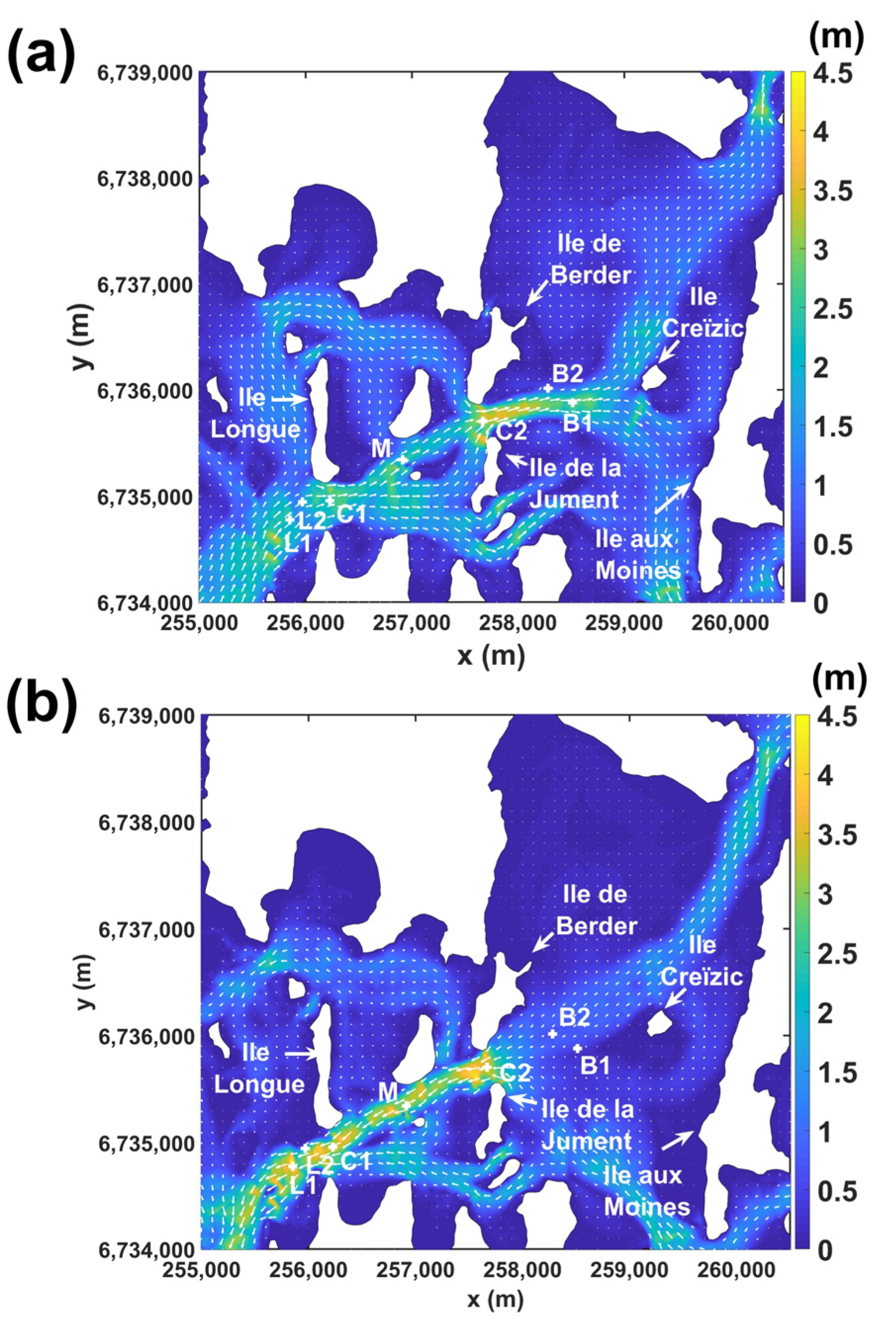
Figure 4 represents the current field during a spring tide at peak flood and ebb. At those two moments of the tide, the maximum current speeds are located within the main channel. At peak flood (Figure 4a), the currents flow towards the east. Eastwards, at “Ile Longue”, the depth decreases progressively. In this area, the current speeds remain high over a distance of approximately 2 km. When the main stream reaches “Ile Creïzic”, it is split into two parts: one flowing to the north and the other to the south. At peak ebb (Figure 4b), the currents flow towards the inlet of the gulf following the main channel. There is a 2 km long zone of high velocity stretching between site No. 2 (south of “Ile de Berder”) and the inlet of the gulf.
From the two criteria described in Section 2.4 (minimum depth and annual mean PD), two zones were deemed suitable for hosting tidal turbines: one located south of “Ile Longue” (site No. 1) and the other located south of “Ile de Berder” (site No. 2). Those zones covered surfaces of 27,712 and 55,987 m2, respectively. They are represented by green lines in the following figures. The number of turbines per site corresponding to the five scenarios described in Section 2.4 is listed in Table 3.

3.2. Impact of Turbines on the Current Speed

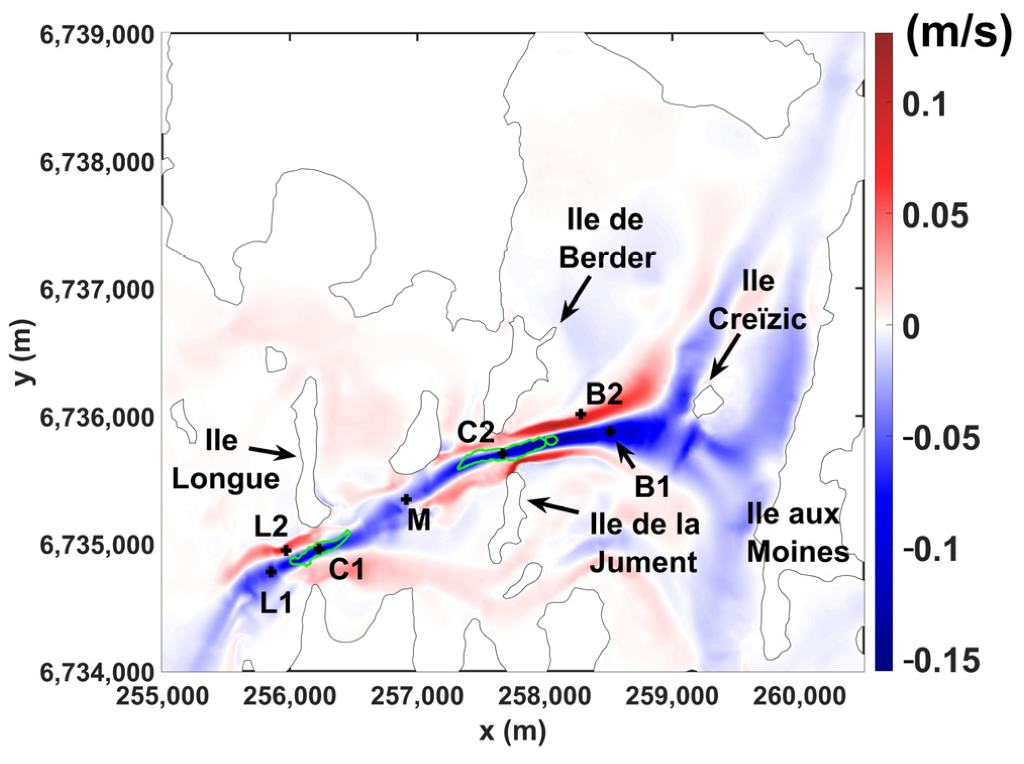
The time–mean perturbation of the flow field resulting from scenario No. 1 is illustrated in Figure 5. This figure shows that the main flow changes are located along the channel and between site No. 2 and “Ile aux Moines”. The time–mean perturbation ranges between −0.16 and +0.13 m/s, which is less than +/−10% of the mean flow velocity. Notably, increases in current speed have comparable magnitude and spatial coverage reductions. This is an unexpected result because, in most cases (at other sites), reductions predominate over increases that generally consist of a slight acceleration in the bypass flow (on both sides of the arrays). The great increase in flow speed obtained here is probably due to the specific configuration of the site where turbines occupy the entire width of the channel. In this configuration, bypass flow can only occur on the shallow sides of the channel, which generates large increases in flow velocity.
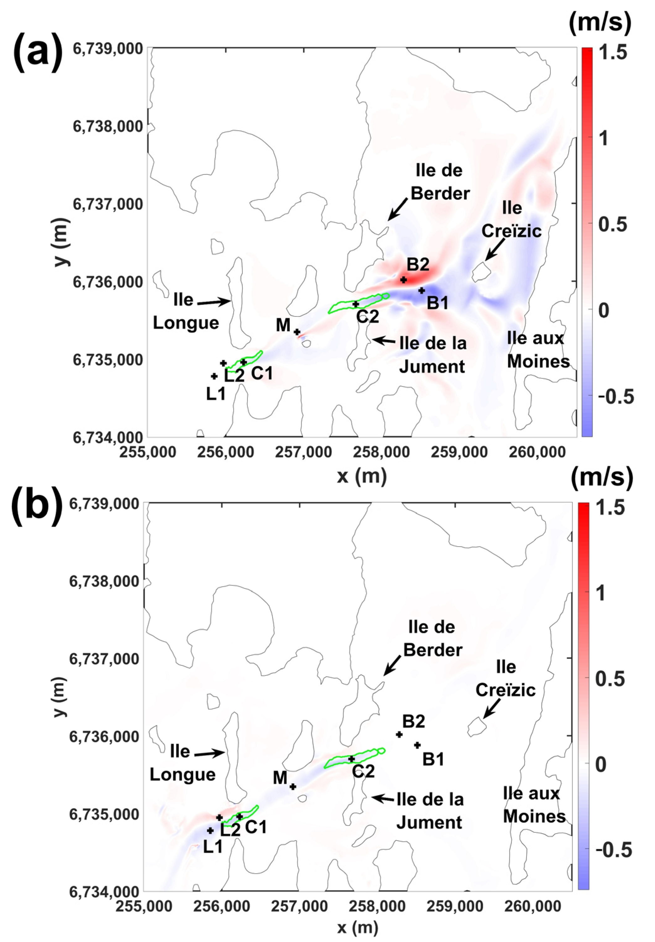
Complementary to the time–mean results, we computed instantaneous changes in the flow field at both peak ebb and flood. Figure 6 shows the spatial distribution of the flow perturbation. Comparably to the time–mean perturbations shown in Figure 5, more considerable changes are located between site No. 2 and “Ile aux Moines” (Figure 6a). Those vaster changes occurred during the flooding tide when the water was flushed into the basin bounded by “Ile aux Moines”, “Ile de Berder”, and “Ile de la Jument” after passing through site No. 2. At ebbing tide (Figure 6b), the perturbation is much smaller in magnitude than during flooding tide, and it remains localised within the channel. To quantify the influence of turbines, the time series of the current velocities was extracted at different locations during a spring tide, which occurred on 8 April 2020. We extracted the data at both sites (“C1” and “C2” in Figure 6; labels “Ile Longue” and “Berder” in Table 4), as well as downstream to the sites, with one location in the reduced speed zone (“L1” and “B1” in the figures; labels “Ile Longue-” and “Berder-” in Table 4) and one location in the accelerated flow zone (“L2” and “B2” in the figures; labels “Ile Longue+” and “Berder+” in Table 4). Results were also extracted between the two sites (“M” in the figures; label “Middle” in Table 4). The results extracted at peak flood and ebb are gathered in Table 4 to compare the scenarios with one another.
Before analysing the flow perturbations, it is important to note that peak ebb velocities dominate over peak flood velocities (ambient conditions). For instance, at “Ile Longue”, the difference in magnitude between peak ebb and flood exceeds 1 m/s. This difference between ebb and flood must be kept in mind when analysing perturbation relative to ambient conditions. The values outlined in Table 4 show that changes in the current speed are small at “Ile Longue”, “Ile Longue−”, and “Ile Longue+” between the two sites (“Middle”) and at site No. 2 (“Berder”). In absolute values, flow changes at these locations are smaller than 0.26 m/s, which is smaller than 11% of the ambient current speed. In contrast, perturbations are very large and reach −0.51 m/s and +1.07 m/s (−19% and +145% of the ambient flow speed) downstream to site No. 2 (“Berder−” and “Berder+”). These large modifications occur during flooding tide when water is flushed into the basin bounded by “Ile aux Moines”, “Ile de Berder”, and “Ile de la Jument” (Figure 6a) after passing through site No. 2. To understand why the flow changes are so important in this area and at this period of the tide cycle, we analysed, in more detail, the ambient characteristics of the flow downstream to site No. 2. Our analysis revealed that the flow is transient and characterised by large horizontal gradients of velocities with fast-moving flow in the axis of the channel and two zones of reduced velocities on each side (Figure 4a). When the turbines operate, the current speed is reduced both within the main channel and at the base of the jet flow, which modifies the location and shape of the latter. The jet flow shortens in its longitudinal axis and widens, which leads to more considerable changes locally, especially in areas that were not in the jet flow but are now, or vice versa (such as at the locations “Berder−” and “Berder+”). The two other reasons why flow changes are greater in this area than in the vicinity of site No. 1 are (i) the greater number of turbines at site No. 2 than there are at site No. 1, hence the greater energy extraction, and (ii) the reduction in the depth downstream to site No. 2. Indeed, site No. 2 is located at the eastern end of the channel; downstream to this site (at flooding tide), the depth rapidly decreases (one kilometre away for site No. 2, the depth is only in the order of 10 m). This rapid change in depth may explain why the perturbation stretches so far horizontally and covers a large portion of the basin.
Regarding the comparison between the different scenarios, we first compare scenarios No. 1 and No. 2. The comparison shows that the half density of the turbines (scenario No. 2) leads to flow perturbation that is approximately twice as small. Except downstream to site No. 2, the perturbation becomes really small (smaller than 0.09 m/s and 5%) at all locations. Downstream to site No. 2 (“Berder−”) and at flooding tide, the perturbation changes from −0.51 m/s (scenario No. 1) to −0.05 m/s (scenario No. 2). Initially, this could be interpreted as the disappearance of flow perturbation. However, assessing perturbation over a longer period of time revealed that, because of the transient flow characteristics, the perturbation oscillates between 0 and −0.4 m/s with a mean value of around −0.2 m/s. Hence, perturbation still exists at this location. The same applies to the location “Berder+”, where an instantaneous value is not fully representative because the perturbation largely oscillates between −0.51 and +0.43 m/s.
The flow interactions between the two sites were then investigated by analysing the results of scenarios Nos. 3 and 4 (one array at a time) and comparing them with the results of scenario No. 1 (both arrays operating simultaneously). When deploying the turbines at site No. 1 only (scenario No. 3), the reduction in flow inside site No. 1 (at “Ile Longue”) is slightly smaller (−0.08 and −0.15 m/s) than when turbines are deployed at the two sites (−0.1 and −0.18 m/s). It shows that the array of site No. 2 slightly reduces the resource of site No. 1. In regard to the flow changes that take place outside site No. 1, they are comparable to whatever turbines are deployed at site No. 1 only or at both sites simultaneously, which suggests that there is no cumulative effect in terms of flow perturbation. Of note, when turbines operate at site No. 1 only, they create a flow perturbation that is transported over a large distance (more than 2 km) during flooding tide. The perturbation is so long that it reaches the jet flow located eastwards to site No. 2, which modifies its neighbouring hydrodynamics. In regard to scenario No. 4, deploying turbines at site No. 2 only leads to perturbations comparable to those obtained when the turbines operate at the two sites. This suggests that site No. 1 has a negligible impact on site No. 2, probably because site No. 1 contains two times fewer turbines. At ebbing tide, the flow perturbations are negligible downstream to “Ile Longue”. This indicates that flow perturbation vanishes rapidly. At flooding tide, large perturbations of the flow occur (once again) downstream to site No. 2. The perturbations are comparable to those obtained when turbines operate at the two sites. Finally, deploying two turbines at site No. 1 (scenario No. 5) causes a very low modification of the current velocities, with all flow changes being smaller than 0.03 m/s.

3.3. Model Limitations

Building a model of the Gulf of Morbihan is challenging because of the high complexity of this coastal system. In this investigation, we opted for a 2D model, which allowed us to obtain good agreement with most field data. It is, however, useful to outline several limitations of our model and point out the implications of these on the results. Firstly, intertidal zones occupy a large portion of the gulf. Simulating the wetting and drying of the elements at the interface between sea and land is a nontrivial modelling challenge [29], and it should be kept in mind that all the physical processes involved in inundation/recession are not captured by the model. Thus, the model results obtained in very shallow water must be interpreted with care. Secondly, the seabed of the studied coastal area is highly heterogenous as it is composed of mud, sand, and rocky seabed and contains oyster farms and vegetated areas that likely add drag to the flow. The calibration of the bottom friction is thus particularly difficult. Improvements in model calibration may be possible with advanced calibration techniques (e.g., [30]). However, this is beyond the scope of this study. Thirdly, as we intended to predict the far-field effects of turbines, we focused on large-scale processes and simplified turbine-scale (sub-grid) processes. In particular, rather than considering the effect of individual turbines (and their potential wake interactions), we considered the global effects of tidal farms on the hydrodynamics of the site. In addition, the effect of turbines only concerned the horizontal (depth-averaged) flow characteristics (and not the flow changes along the vertical direction, especially the bypass flow that should occur above and below the turbines). It is thus important to remember that our results only apply to the scale of the gulf and not to the scale of the turbines, where the action of the turbines on the flow is simplified. Finally, the changes in velocity induced by the turbines may modify the sediment transport, hence the seabed morphology. This is not included in this study (where the morphology does not change). In future works, it might be interesting to study the feedback between the changes in hydrodynamics and modifications of the morphology.

3.4. Applicability of the Results to Other Sites

Despite the limitations described in Section 3.3, we obtained results that can be applied to other sites with comparable characteristics (i.e., shallow water, narrow channels, and channels that open out into the basin). Firstly, we found that high increases in current speed may occur on the sides of the channel. This is certainly due to the fact that, in the scenarios retained here, turbines occupy the entire width of the channel. This result is consistent with earlier studies demonstrating the importance of the spatial distribution of turbines across the channel (hence blockage) on flow perturbation [31]. This is also consistent with numerical studies indicating that tidal energy sites that are bounded laterally are more prone to cause large increases in current speed [25,32] than sites where the bypass flow is less constrained, e.g., sites located in open sea or large sites where turbines only occupy a portion of the channel [11,12]. Secondly, we found that the exploitation of tidal stream energy in a channel that opens out into a basin may cause significant flow perturbations locally, especially at the base of the jet flow. Similar perturbations should also occur at sites with comparable flow configurations.

4. Conclusions

The Gulf of Morbihan is characterised by very high current velocities. Two sites are particularly suited for harvesting tidal stream energy. They are located along a narrow channel connecting the sea to the inner (shallow) part of the gulf. The first site is located south of Ile Longue and has the potential to host up to sixteen 8 m diameter turbines. The second site has a greater spatial coverage and has the potential to host up to 32 turbines (of similar size).
Simulations with turbines represented as enhanced friction indicated that, during ebbing tide, flow perturbations follow the main channel. They remain small in magnitude and vanish rapidly. However, during flooding tide, the reduction in the flow speed caused by the energy extraction modifies the flow structure of the area located eastwards of the second site (south of Ile de Berder). The configuration is such that, immediately after passing through the site, currents are flushed into a 2 × 5 km2 basin with reduced depth. This particular configuration creates a jet flow whose properties are modified by the exploitation of the currents; the jet shortens in the direction of the flow and enlarges laterally. This modification generates more extensive changes locally, especially where the velocity gradient (between areas of slow- and fast-moving flows) is strong. Furthermore, the basin receiving the jet flow is shallower than the main tidal channel. Thus, at flooding tide, the perturbation stretches horizontally and occupies a large portion of the basin.
Simulations with fewer turbines or with arrays operating one at a time were also performed. The results showed that the level of perturbation depended on the number and location of the turbines. It was found that reducing the number of turbines by a factor of two led to twice as small changes in the flow velocities. Even if sites are located close to one another (the distance between the two sites is smaller than 2 km), they behave nearly independently of each other; the site located south of Ile Longue has a limited influence on the site located south of Berder. On the other hand, the site of Berder (which can host more turbines) slightly reduces the resources of the site located south of Ile Longue during ebbing tide. In terms of perturbation, no cumulative effects were found. Finally, the test scheduled by MH56 (two turbines) is expected to have a negligible effect on the current speeds.
To conclude, the Gulf of Morbihan has the potential to host dozens of turbines (up to 48 devices with a rated power of 300 kW). If such a large number of devices are to be deployed, attention must be paid to their influence on the physical environment, especially in the basin located eastwards of Ile de Berder.

Author Contributions

Conceptualization, J.T.; methodology, J.T.; software, J.T. and M.S.; validation, J.T. and M.S.; formal analysis, J.T., M.S. and S.G.; investigation, J.T., M.S. and S.G.; resources, J.T., M.S. and S.G.; data curation, J.T. and M.S.; writing—original draft preparation, J.T.; writing—review and editing, J.T., M.S. and S.G.; project administration, M.S. and S.G.; funding acquisition, M.S. and S.G. All authors have read and agreed to the published version of the manuscript.

Funding

This research was funded by the Interreg VA France (Channel) England Programme, which funds the TIGER project.

Institutional Review Board Statement

Not applicable.

Informed Consent Statement

Not applicable.

Data Availability Statement

The data presented in this study are available on request from the corresponding author.

Acknowledgments

The authors are grateful to the CRIANN for their help in using their computational resource and to the French navy, SHOM (“Service Hydrographique et Océanographique de la Marine”), for providing access to bathymetric and sedimentological data. This work was supported by the Tidal Stream Industry Energiser project (TIGER), co-financed by the European Regional Development Fund through the INTERREG France (Channel) England Programme: Interreg VA.

Conflicts of Interest

The authors declare no conflicts of interest.

References

  1. Sentchev, A.; Thiébot, J.; Bennis, A.-C.; Piggott, M. New insights on tidal dynamics and tidal energy harvesting in the Alderney Race. Philos. Trans. R. Soc. A 2020, 378, 20190490. [Google Scholar] [CrossRef]
  2. Draper, S.; Adcock, T.A.A.; Borthwick, A.G.L.; Houlsby, G.T. Estimate of the tidal stream power resource of the Pentland Firth. Renew. Energy. 2014, 63, 650–657. [Google Scholar] [CrossRef]
  3. Karsten, R.H.; McMillan, J.M.; Lickley, M.J.; Haynes, R.D. Assessment of tidal current energy in the Minas Passage, Bay of Fundy. Proc. Inst. Mech. Eng. Part A J. Power Energy 2008, 222, 493–507. [Google Scholar] [CrossRef]
  4. Guillou, N.; Charpentier, J.-F.; Benbouzid, M. The Tidal Stream Energy Resource of the Fromveur Strait—A Review. J. Mar. Sci. Eng. 2020, 8, 1037. [Google Scholar] [CrossRef]
  5. Richardson, R.L.; Buckham, B.; Mc Whinnie, L.H. Mapping a blue energy future for British Columbia: Creating a holistic framework for tidal stream energy development in remote coastal communities. Renew. Sustain. Energy Rev. 2022, 157, 112032. [Google Scholar] [CrossRef]
  6. Mestres, M.; Cerralbo, P.; Grifoll, M.; Sierra, J.P.; Espino, M. Modelling assessment of the tidal stream resource in the Ria of Ferrol (NW Spain) using a year-long simulation. Renew. Energy 2019, 131, 811–817. [Google Scholar] [CrossRef]
  7. Carballo, R.; Iglesias, G.; Castro, A. Numerical model evaluation of tidal stream energy resources in the Ría de Muros (NW Spain). Renew. Energy 2009, 34, 1517–1524. [Google Scholar] [CrossRef]
  8. Wang, T.; Yang, Z. A modeling study of tidal energy extraction and the associated impact on tidal circulation in a multi-inlet bay system of Puget Sound. Renew. Energy 2017, 114, 204–214. [Google Scholar] [CrossRef]
  9. Simonsen, K.; Niclasen, B.A. Analysis of the energy potential of tidal streams on the Faroe Shelf. Renew. Energy 2021, 163, 836–844. [Google Scholar] [CrossRef]
  10. Firdaus, A.M.; Houlsby, G.T.; Adcock, T.A.A. Tidal energy resource in Larantuka Strait, Indonesia. Proc. Inst. Civ. Eng.-Energy 2020, 173, 81–92. [Google Scholar] [CrossRef]
  11. Fairley, I.; Masters, I.; Karunarathna, H. The cumulative impact of tidal stream turbine arrays on sediment transport in the Pentland Firth. Renew. Energy 2015, 80, 755–769. [Google Scholar] [CrossRef]
  12. Thiébot, J.; Bailly du Bois, P.; Guillou, S. Numerical modeling of the effect of tidal stream turbines on the hydrodynamics and the sediment transport—Application to the Alderney Race (Raz Blanchard), France. Renew. Energy 2015, 75, 356–365. [Google Scholar] [CrossRef]
  13. Ashall, L.M.; Mulligan, R.P.; Law, B.A. Variability in suspended sediment concentration in the Minas Basin, Bay of Fundy, and implications for changes due to tidal power extraction. Coast. Eng. 2016, 107, 102–115. [Google Scholar] [CrossRef]
  14. Chen, W.-B.; Liu, W.-C.; Hsu, M.-H. Modeling evaluation of tidal stream energy and the impacts of energy extraction on hydrodynamics in the Taiwan Strait. Energies 2013, 6, 2191–2203. [Google Scholar] [CrossRef]
  15. Du Feu, R.; Funke, S.; Kramer, S.; Culley, D.; Hill, J.; Halpern, B.; Piggott, M. The trade-off between tidal-turbine array yield and impact on flow: A multi-objective optimisation problem. Renew. Energy 2017, 114, 1247–1257. [Google Scholar] [CrossRef]
  16. Ahmadian, R.; Falconer, R.; Bockelmann-Evans, B. Far-field modelling of the hydro-environmental impact of tidal stream turbines. Renew. Energy 2012, 38, 107–116. [Google Scholar] [CrossRef]
  17. Zhang, J.; Zhang, C.; Angeloudis, A.; Kramer, S.C.; He, R.; Piggott, M.D. Interactions between tidal stream turbine arrays and their hydrodynamic impact around Zhoushan Island, China. Ocean Eng. 2022, 246, 110431. [Google Scholar] [CrossRef]
  18. Goss, Z.L.; Coles, D.S.; Piggott, M.D. Identifying economically viable tidal sites within the Alderney Race through optimization of levelized cost of energy. Philos. Trans. R. Soc. A 2020, 378, 20190500. [Google Scholar] [CrossRef]
  19. Van Der Molen, J.; Rogers, S.; Ellis, J.; Fox, C.; Mc Cloghrie, P. Dispersal patterns of the eggs and larvae of spring-spawning fish in the Irish Sea, UK. J. Sea Res. 2007, 58, 313–330. [Google Scholar] [CrossRef]
  20. Kadiri, M.; Ahmadian, R.; Bockelmann-Evans, B.; Rauen, W.; Falconer, R. A review of the potential water quality impacts of tidal renewable energy systems. Renew Sustain. Energy Rev. 2012, 16, 329–341. [Google Scholar] [CrossRef]
  21. Nash, S.; Phoenix, A. A review of the current understanding of the hydro-environmental impacts of energy removal by tidal turbines. Renew Sustain. Energy Rev. 2017, 80, 648–662. [Google Scholar] [CrossRef]
  22. Sedrati, M.; Mrani Alaoui, M.; Laly, C. Social perception and acceptance of Tidal Current Turbines (TCT’s) Energy project: A case study of the Gulf of Morbihan. In Proceedings of the 14th European Wave and Tidal Energy Conference, Plymouth, UK, 5–9 September 2021. [Google Scholar]
  23. Hervouet, J.-M. Hydrodynamics of Free Surface Flows, Modelling with the Finite-Element Method; John Wiley & Sons Ltd.: West Sussex, UK, 2020; 340p. [Google Scholar]
  24. Black and Veatch. UK Tidal Current Resource and Economics. Commissioned by the Carbon Trust and Power. Project number 121393. 2011, p. 51. Available online: https://www.carbontrust.com/our-work-and-impact/guides-reports-and-tools/accelerating-marine-energy (accessed on 9 March 2024).
  25. Plew, D.R.; Stevens, C.L. Numerical modelling of the effect of turbines on currents in a tidal channel—Tory Channel, New Zealand. Renew. Energy 2013, 57, 269–282. [Google Scholar] [CrossRef]
  26. Divett, T.; Vennell, R.; Stevens, C. Optimization of multiple turbine arrays in a channel with tidally reversing flow by numerical modelling with adaptive mesh. Philos. Trans. R. Soc. A Math. Phys. Eng. Sci. 2013, 371, 20120251. [Google Scholar] [CrossRef] [PubMed]
  27. Yang, Z.; Wang, T.; Copping, A.E. Modeling tidal stream energy extraction and its effects on transport processes in a tidal channel and bay system using a three-dimensional coastal ocean model. Renew. Energy 2013, 50, 605–613. [Google Scholar] [CrossRef]
  28. Martin-Short, R.; Hill, J.; Kramer, S.C.; Avdis, A.; Allison, P.A.; Piggott, M.D. Tidal resource extraction in the Pentland Firth, UK: Potential impacts on flow regime and sediment transport in the inner sound of stroma. Renew. Energy 2015, 76, 596–607. [Google Scholar] [CrossRef]
  29. Medeiros, S.C.; Hagen, S.C. Review of wetting and drying algorithms for numerical tidal flow models. Int. J. Numer. Methods Fluids 2013, 71, 473–487. [Google Scholar] [CrossRef]
  30. Zaoui, F.; Goeury, C.; Audoin, Y. A metamodel of the Telemac errors. In Proceedings of the 26th Telemac-Mascaret user Conference, Toulouse, France, 15–17 October 2019. 7p. [Google Scholar]
  31. Nishino, T.; Willden, R. The efficiency of an array of tidal turbines partially blocking a wide channel. J. Fluid Mech. 2012, 708, 596–606. [Google Scholar] [CrossRef]
  32. Nash, S.; Olbert, A.I.; Hartnett, M. Towards a Low-Cost Modelling System for Optimising the Layout of Tidal Turbine Arrays. Energies 2015, 8, 13521–13539. [Google Scholar] [CrossRef]
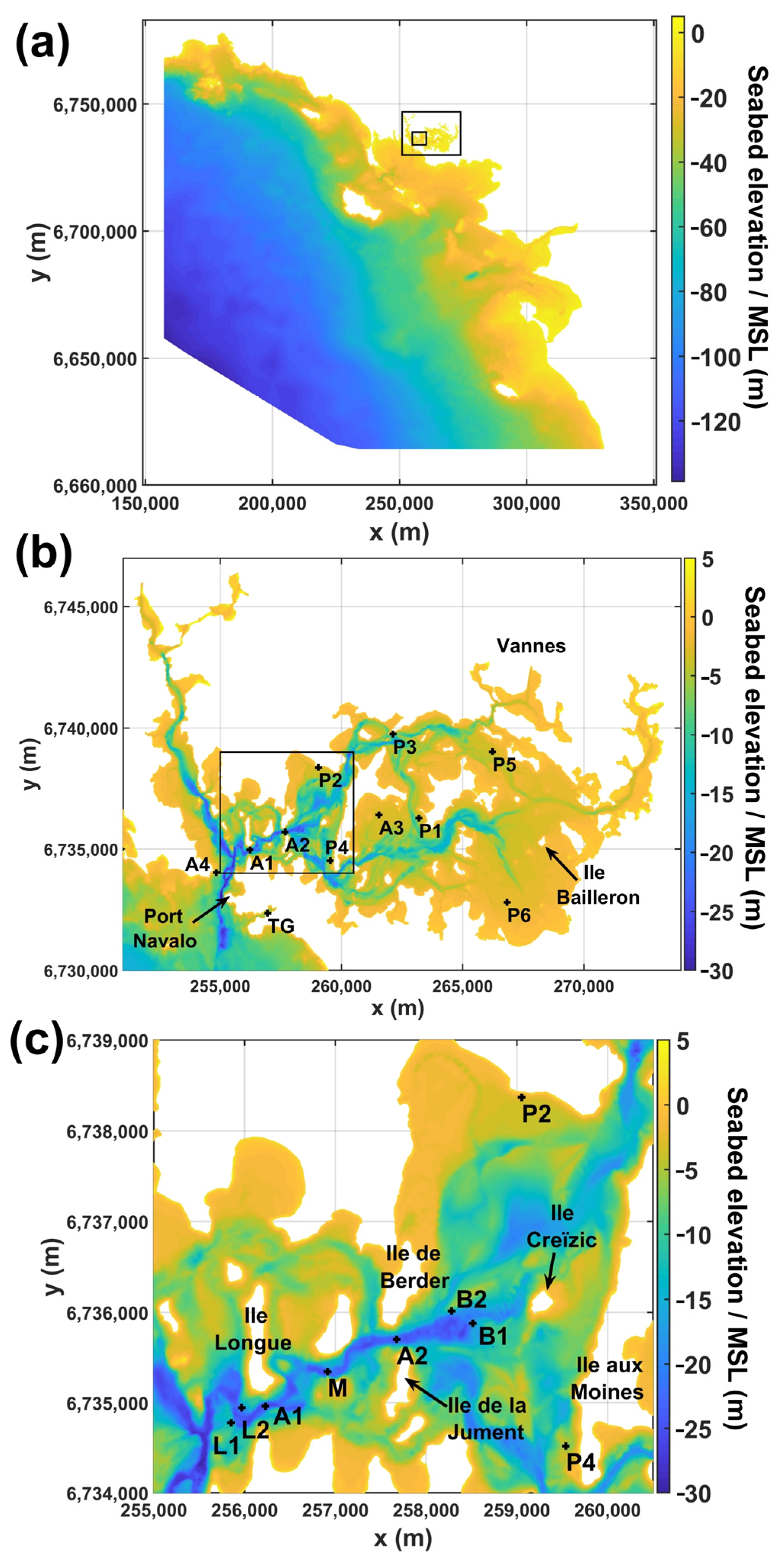
Figure 1. Bathymetry of the Gulf of Morbihan and locations of the field measurements. (a) The entire coastal region; (b) the Gulf of Morbihan; (c) the tidal stream energy sites; and the main channel. Coordinates are in meters (EPSG 4326).
Jmse 12 00479 g001
Figure 2. Evolution of the induction factor; thrust and power coefficients as functions of the current speed.
Jmse 12 00479 g002
Figure 3. Comparison between depth-averaged current speeds predicted by the model (red and yellow curves) and measured by ADCPs (blue curves). Subplots (a,b) correspond to the site located south of “Ile Longue” (same location but different time series lengths). Subplots (c,d) correspond to the site located south of “Berder” (same location but different time series lengths). The yellow curves were obtained by moving the point where the data were extracted by 100 m.
Jmse 12 00479 g003
Figure 4. Current velocities at peak flood (a) and ebb (b) during a spring tide (8 April 2020). Coordinates are in meters (EPSG 4326).
Jmse 12 00479 g004
Figure 5. Time–mean perturbation of the current velocity magnitude in m/s (scenario No. 1). Locations of tidal farms are indicated with green lines. Coordinates are in meters (EPSG 4326).
Jmse 12 00479 g005
Figure 6. Perturbation of the current velocity magnitude in m/s (scenario No. 1) at peak flood (a) and ebb (b) during a spring tide (8 April 2020). Locations of tidal farms are indicated with green lines. Coordinates are in meters (EPSG 4326).
Jmse 12 00479 g006
Table 1. Locations (EPSG 4326) of instruments and periods retained for the calibration and validation of the model.
NameType of SensorLocationPeriod
A1 (Ile Longue)ADCP256,229; 6,734,96016 December 2014–14 January 2015
A2 (Berder)ADCP257,676; 6,735,70116 December 2014–10 January 2015
A3 (Brest)ADCP261,548; 6,736,41018 February 2019–8 March 2019
A4 (UBS)ADCP254,840; 6,734,02618 February 2019–8 March 2019
P1Pressure sensor263,192; 6,736,27519 February 2019–7 March 2019
P2Pressure sensor259,052; 6,738,36919 February 2019–7 March 2019
P3Pressure sensor262,124; 6,739,74819 February 2019–7 March 2019
P4Pressure sensor259,539; 6,734,51919 February 2019–7 March 2019
P5Pressure sensor266,227; 6,739,02019 February 2019–7 March 2019
P6Pressure sensor266,833; 6,732,81119 February 2019–7 March 2019
TG (Le Crouesty)Tidal gauge256,959; 6,732,36116 December 2014–14 January 2015 and 19 February 2019–7 March 2019
Table 2. Characteristics of the three-bladed turbine. Power and thrust coefficients are constant when the current speed is lower than the rated speed.
CharacteristicValue
Power coefficient, Cp0.4
Thrust coefficient, Ct0.7
Nominal power313 kW
Rotor diameter8 m
Area swept by the blades, A50.3 m2
Hub height10 m
Rated speed, Urated3.1 m/s
Table 3. Number of turbines per site.
ScenarioSite No. 1Site No. 2
11632
2816
3160
4032
520
Table 4. Ambient velocity magnitude and flow perturbation (in m/s) at specific locations. “US” refers to configurations where the location is located upstream to the turbines (and is not affected by the turbines).
NameAmbient ConditionsScenario No. 1Scenario No. 2Scenario No. 3Scenario No. 4
FloodEbbFloodEbbFloodEbbFloodEbbFloodEbb
Ile Longue (C1)2.433.53−0.1−0.18−0.05−0.09−0.08−0.15−0.01−0.03
Ile Longue− (L1)2.314.27US−0.26US−0.12US−0.23US−0.03
Ile Longue+ (L2)1.441.78US0.19US0.09US0.19US0
Middle (M)2.212.99−0.07−0.08−0.03−0.04−0.05USUS−0.06
Berder (C2)3.313.43−0.16−0.19−0.08−0.10−0.01−0.17−0.18
Berder− (B1)2.650.44−0.51US−0.05US0.09US−0.47US
Berder+ (B2)0.720.711.07US−0.51US−0.14US0.66US
Disclaimer/Publisher’s Note: The statements, opinions and data contained in all publications are solely those of the individual author(s) and contributor(s) and not of MDPI and/or the editor(s). MDPI and/or the editor(s) disclaim responsibility for any injury to people or property resulting from any ideas, methods, instructions or products referred to in the content.