A Comprehensive Investigation of Linear and Nonlinear Beam Models on Flexible Wind Turbine Blade Load Calculations
Abstract
:1. Introduction
2. Methodology
2.1. Orthogonal Transformation Matrix
2.2. Coordinate Frames and Transformations
- (1)
- First, a global inertial Cartesian frame, , was established, in which is oriented vertically upward and aligns with the horizontal component of the incoming wind velocity.
- (2)
- The nacelle frame, , was constructed by rotating the global frame, , about by the yaw angle, , then rotating it in the new frame about by the tilt angle, η. The transformation relationship can be expressed by , where .
- (3)
- The hub frame, , was constructed by rotating the nacelle frame, , about by the azimuth angle, θazi. The transformation relationship can be expressed by Ehj = RaziEnj, where Razi = R([0,0,θazi]T).
- (4)
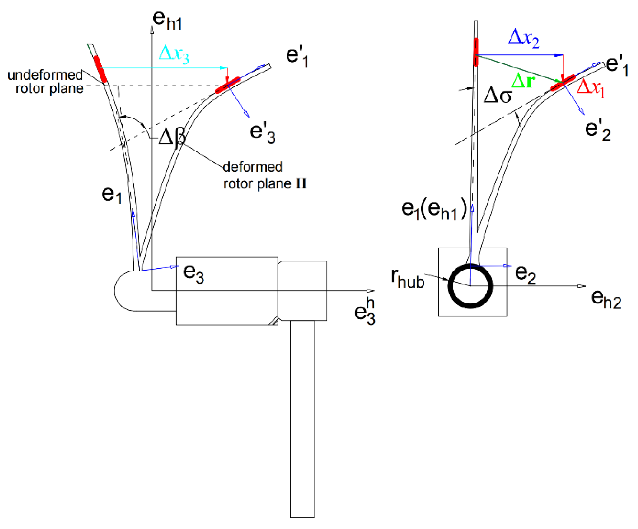
- The blade root frame, erj{o;er1,er2,er3}, was established by rotating the hub frame, , about by the cone angle, β, then rotating it in the new coordinate system about by the sweep angle, σ. The transformation relationship is expressed by , where and . For modeling convenience, it was assumed that the blade root frame does not change with the pitch motion.
2.3. Structural Solver Based on GEB Theory
2.3.1. Beam Frame and Kinematic Assumptions
2.3.2. Implementation Details
- 1.
- A two-node linear Lagrangian interpolation polynomial was employed within each finite element to interpolate the position vectors and rotation vectors of the nodes. To avoid shear locking in the stiffness matrix, reduced Gaussian integration (single-point integration) was utilized when computing the stiffness matrix.
- 2.
- To overcome the singularity associated with the rotation vector when , which was mentioned in Section 2.1, and to ensure that the rotation vectors of various nodes are not affected by the Ψ correction during interpolation, an updated Lagrangian method was used for the interpolation of the finite rotation vectors. Thus, after completing one step of convergent iteration, the orthogonal transformation matrix, R, of the current configuration was saved. In the next iteration step, the information saved at the node was the rotation vector corresponding to the rotation increment between the previous and current configurations; this method was extended to the two nodes of the element. Thus, the total rotation of the current configuration can be expressed by Equation (15):where represents the rotation configuration of the previous convergent configuration, is the rotation matrix for the current rotation increment, and is the rotation increment vector, which can be linearly interpolated between two nodes.
- 3.
- Since an energy dissipation term was introduced into the HHT-α method, which is based on the Newmark method [35,36], to enhance numerical stability and ensure second-order accuracy, it was adopted for numerical integration of the dynamic equations to guarantee stability during lengthy simulations of wind turbine systems.
2.4. GE-BEM Aerodynamic Model
2.5. Gravitational and Centrifugal Force Load Calculations
2.6. Coupling Method
3. Numerical Results
3.1. Benchmark Static Analysis with the 45° Pre-Curved Beam
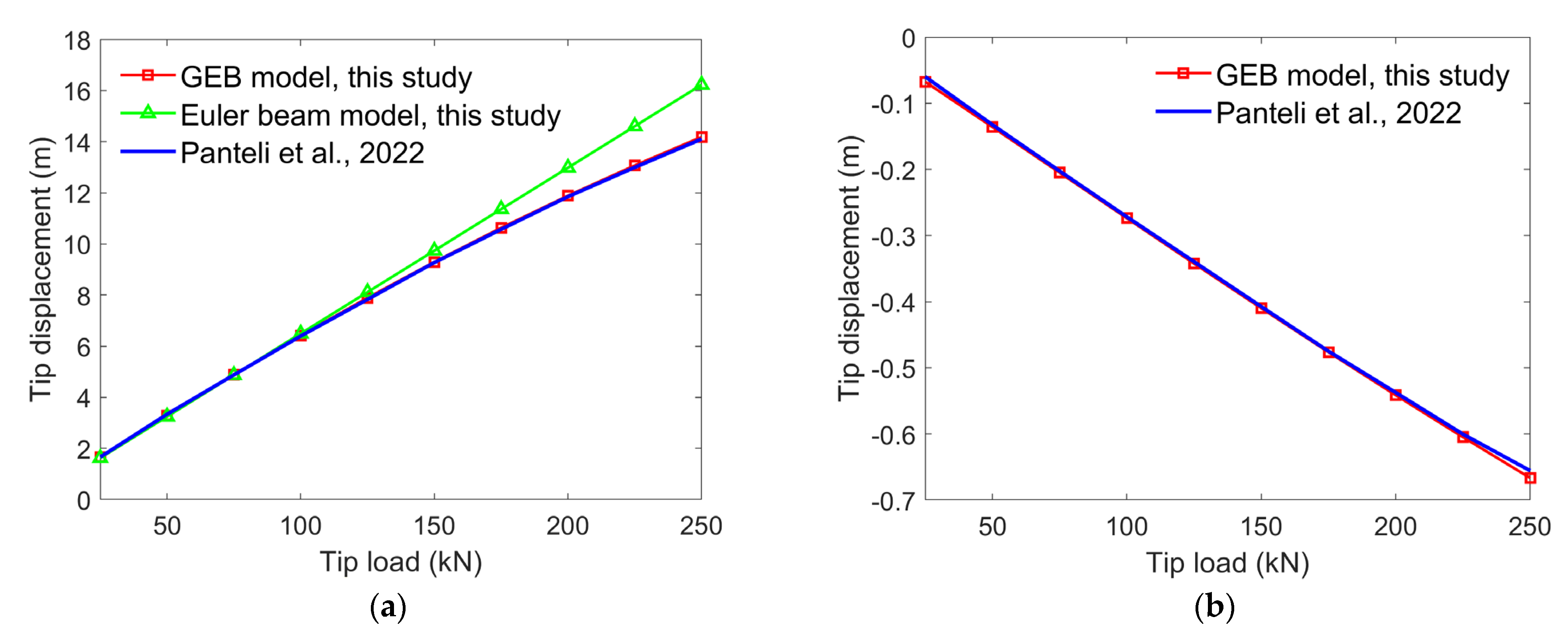
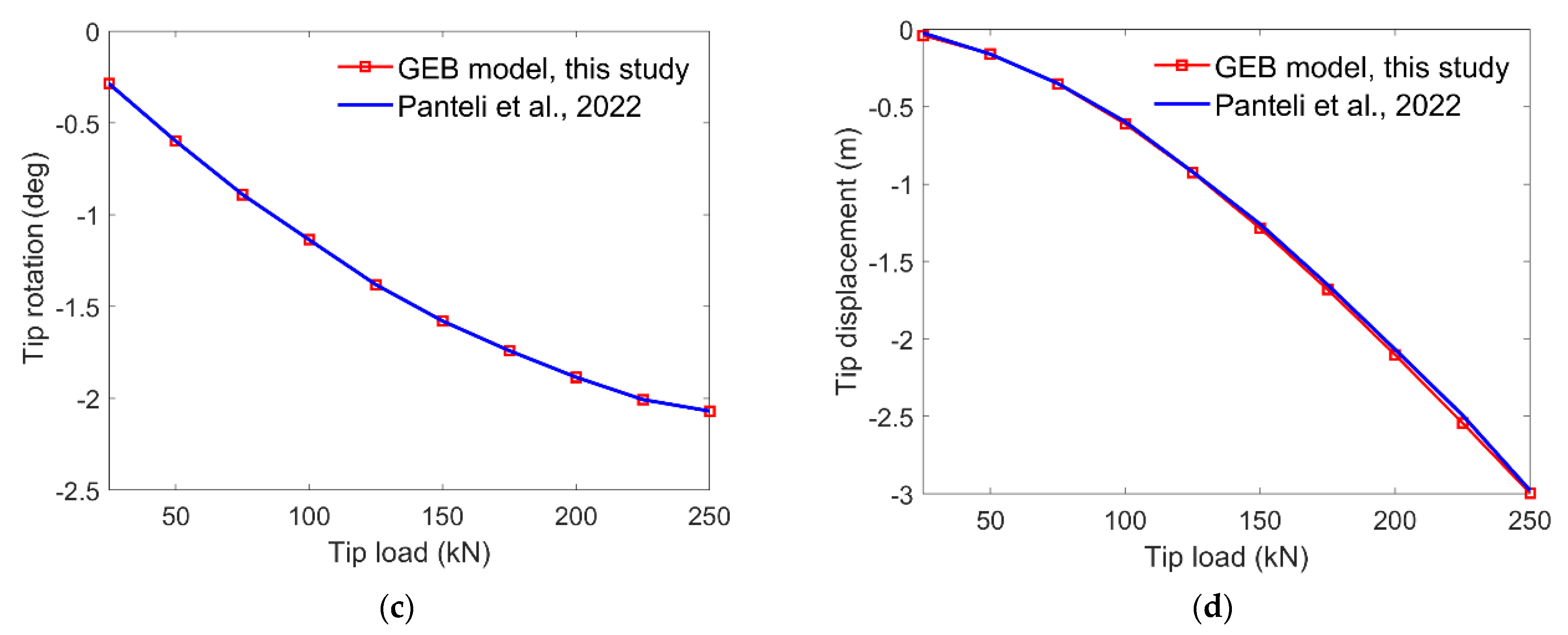
3.2. Static Deformation Analysis of the 10 MW RWT
3.3. Benchmark Dynamic Analysis with the 45° Pre-Curved Beam
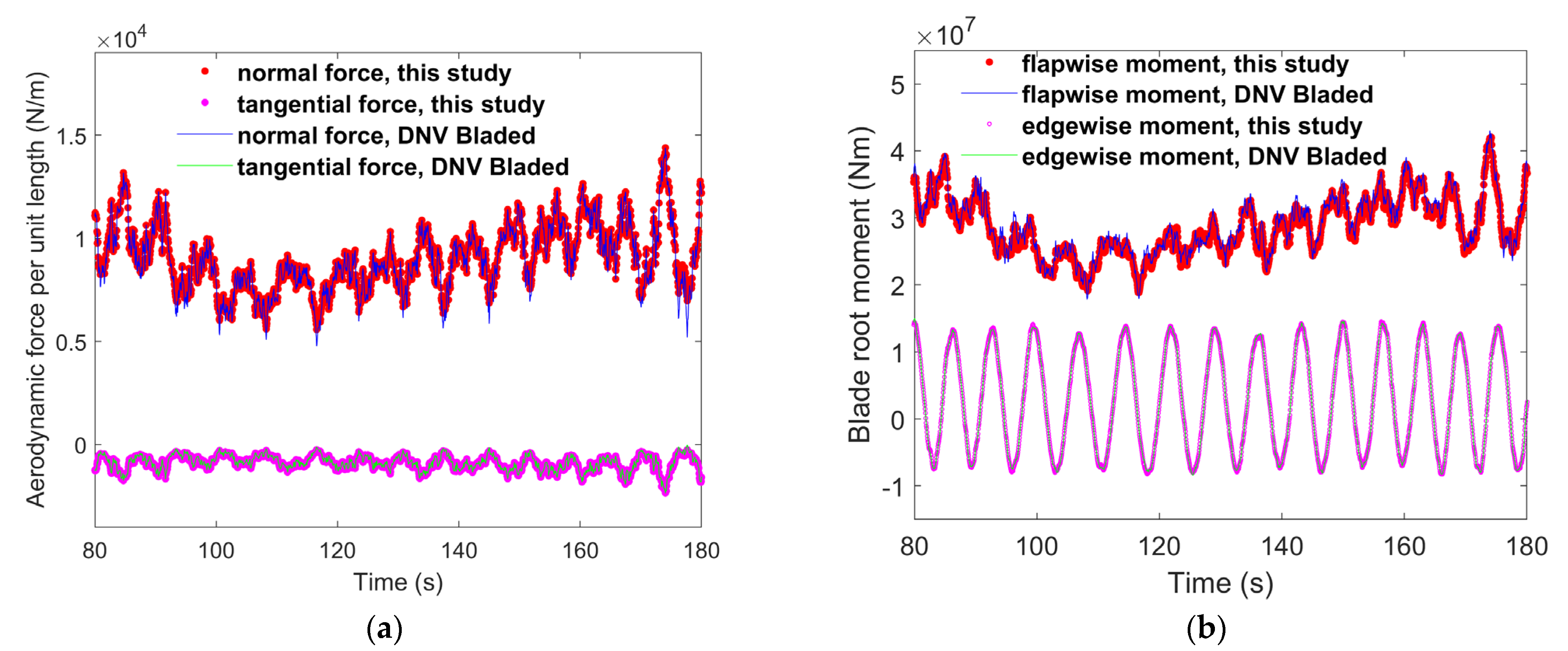
3.4. Load Calculations for the 10 MW RWT
3.5. Aeroelastic Simulations of the 10 MW RWT
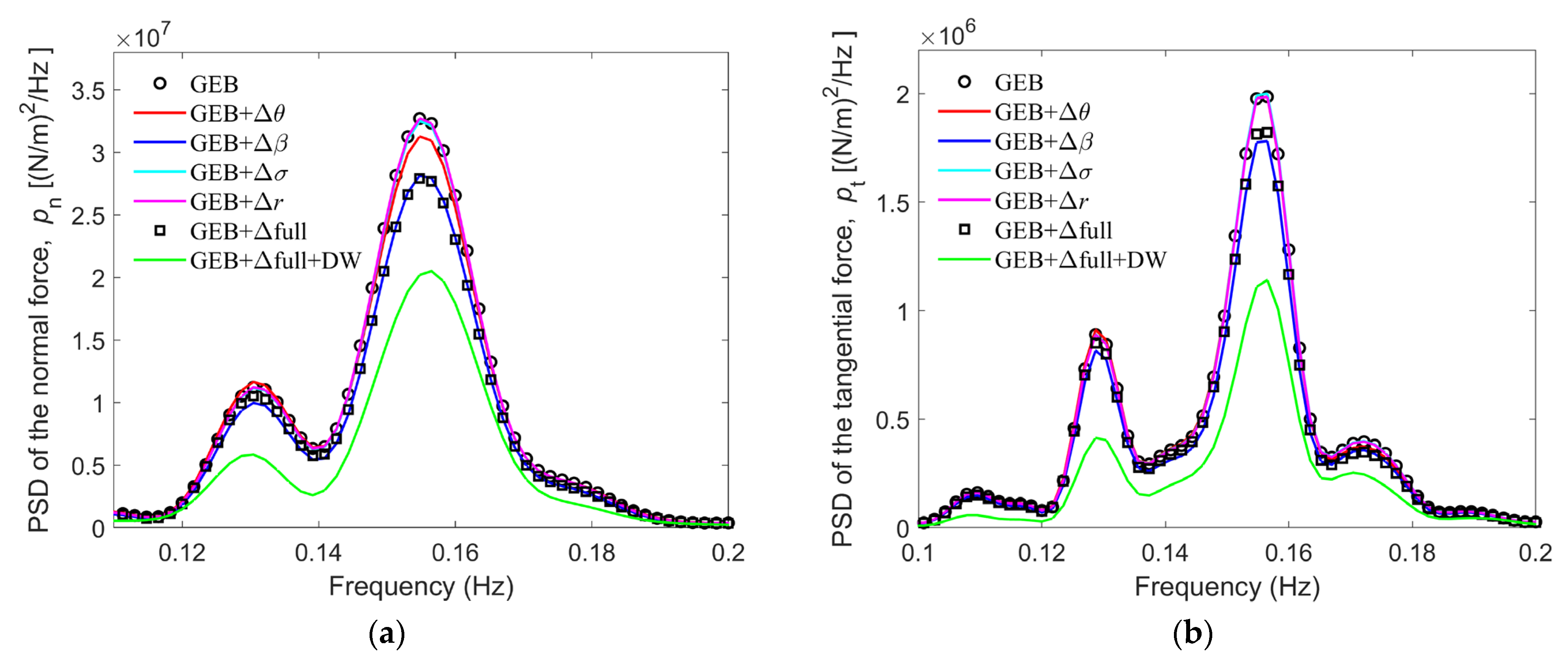
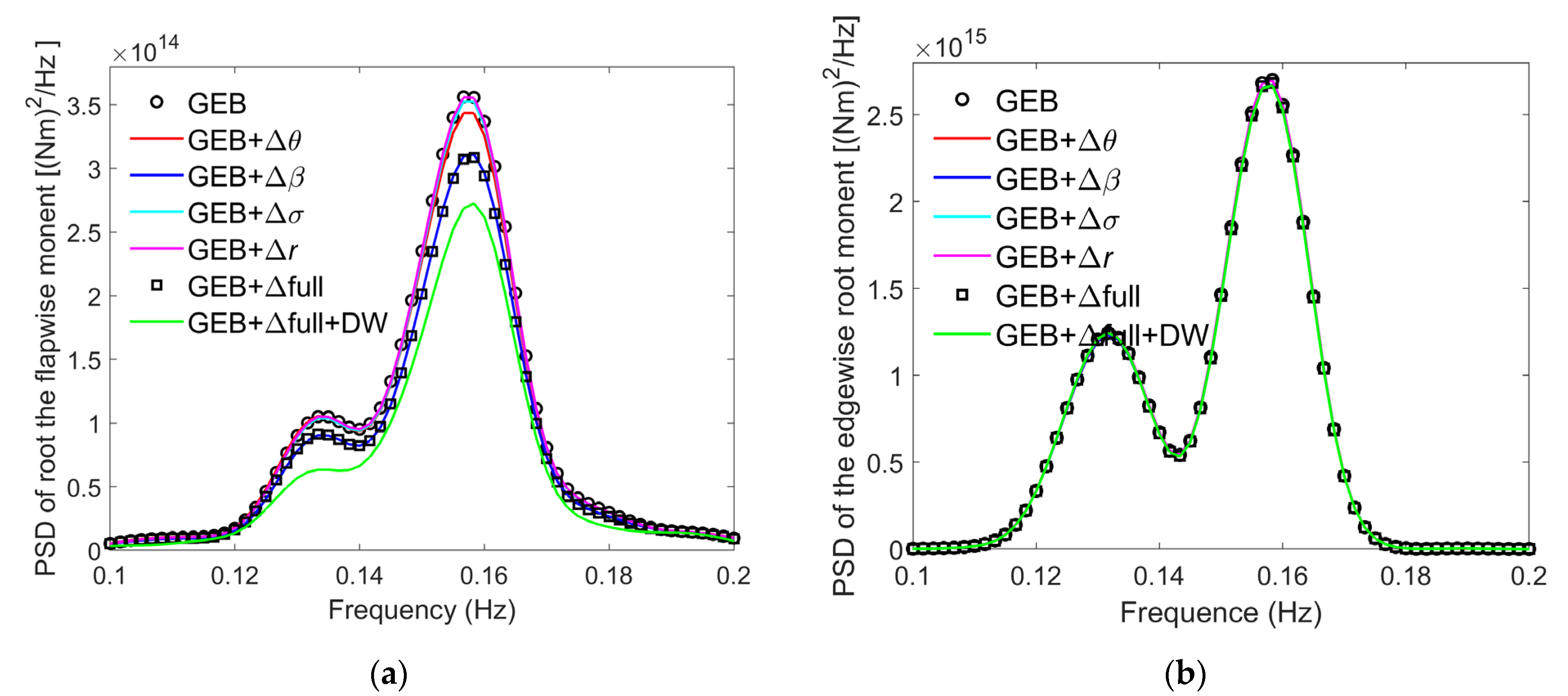
3.6. Influence of Deformation on the Blade Loads
- 1.
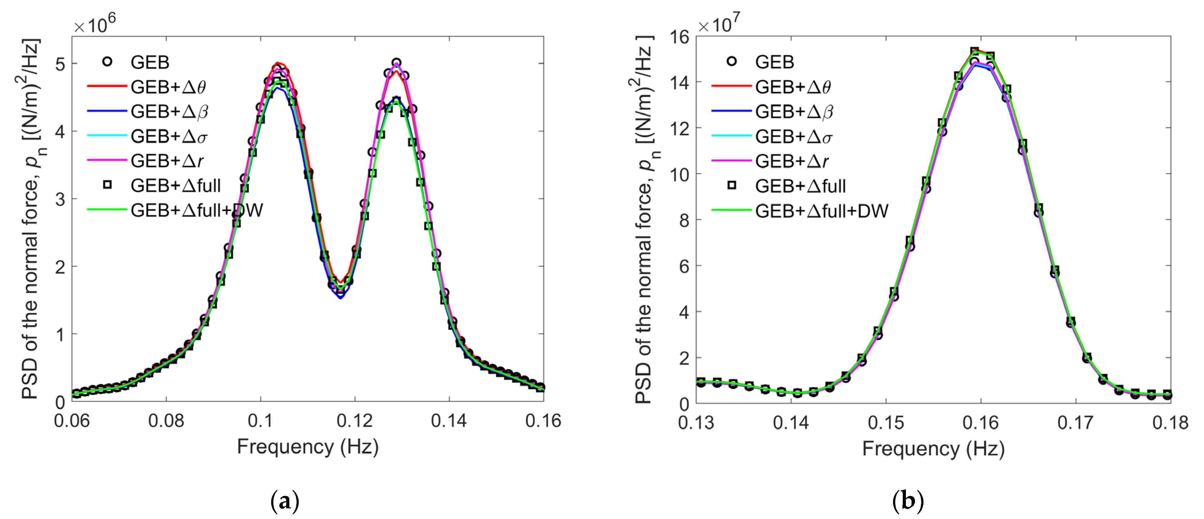
- A model was established with no deformation corrections or dynamic wake effects; it is referred to as GEB.
- 2.
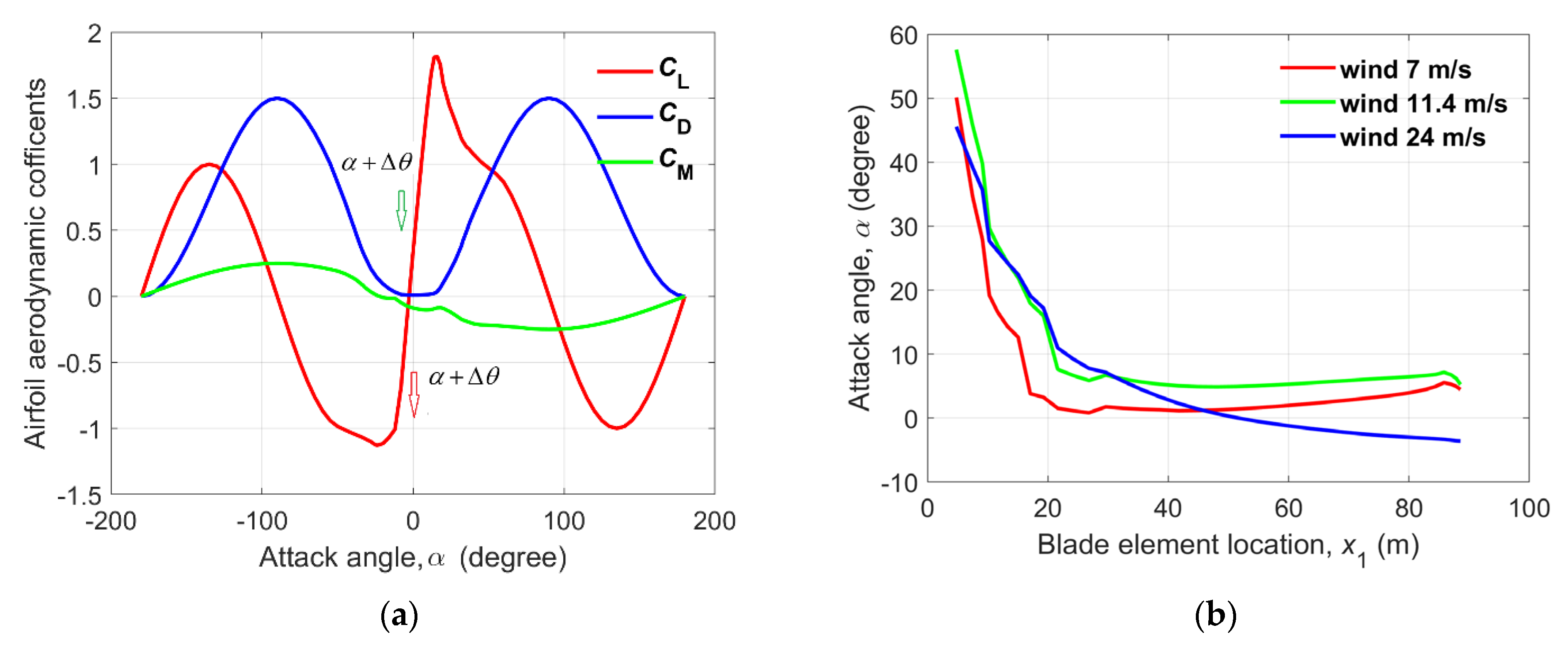
- A model was established with only a torsional deformation correction, ; it is referred to as GEB + .
- 3.
- Another model, referred to GEB + , included only a flapwise deformation correction, .
- 4.
- Only an edgewise deformation correction, , was included in the fourth model, which is referred to as GEB + .
- 5.
- A model was established with a blade element location change correction, Δr; this model is referred to as GEB + Δr.
- 6.
- A sixth model, referred to as GEB + , was established; it included all four corrections mentioned previously.
- 7.
- The last model included all four corrections and a dynamic wake model; this model is referred to as GEB + Δfull + DW.
3.7. Structural Nonlinearity Effects on the Aeroelastic Loads
- (1)
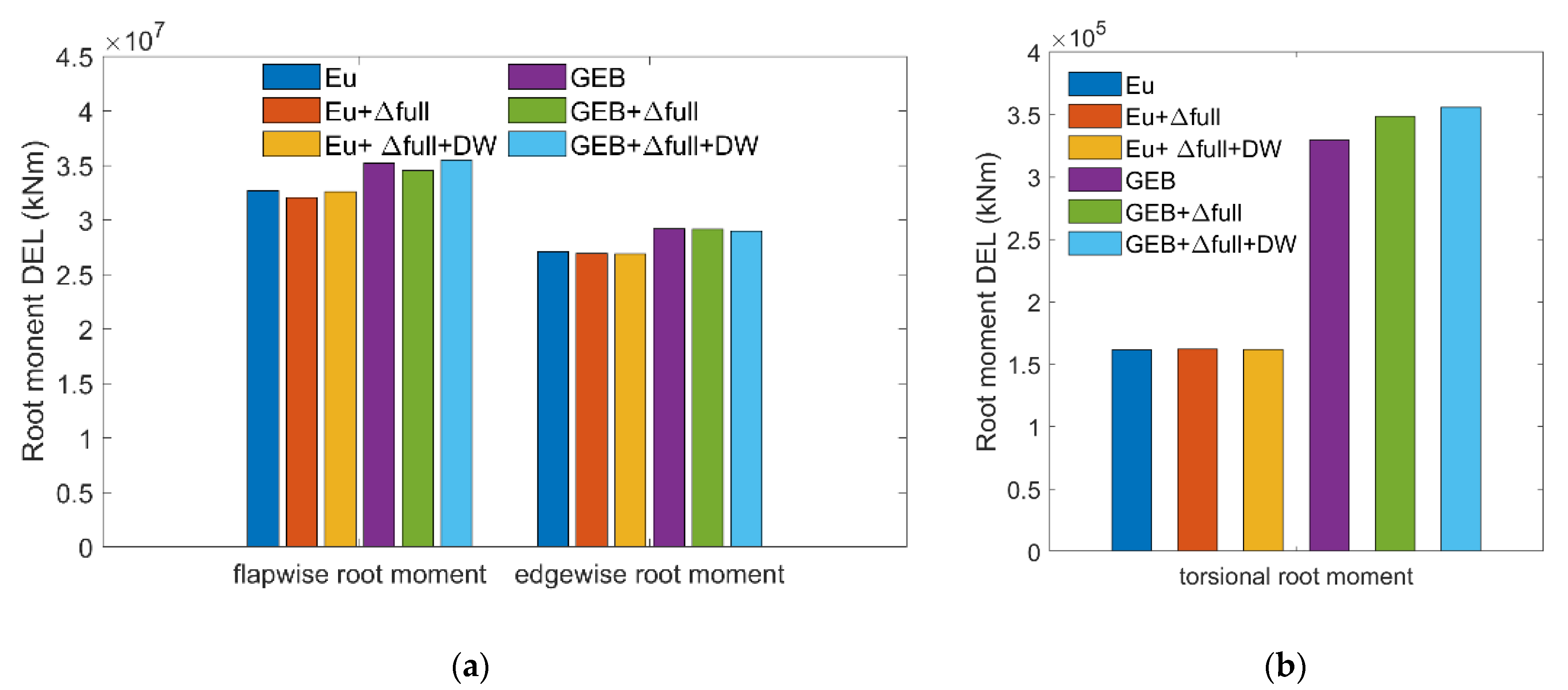
- The differences between the results of the GEB + Δfull and GEB models can characterize the wind turbine blade deformation effects on the fatigue loads of the blade during its lifetime. The relative differences between the GEB + Δfull and GEB results in Table 2 show that the torsional root load is most affected by blade deformations, which caused a 5.73% increase in the DEL. Blade deformations have relatively smaller impacts on the flapwise root fatigue load, reducing the DEL by only 1.88%, while they have almost no effect on the edgewise root fatigue load.
- (2)
- The differences between the results generated by the GEB + Δfull + DW and GEB models reflect the dynamic wake effects on the blade fatigue loads. The relative differences between the results of these models presented in Table 2 indicate that the dynamic wake increases both the flapwise and torsional root fatigue loads but reduces the edgewise root fatigue load.
- (3)
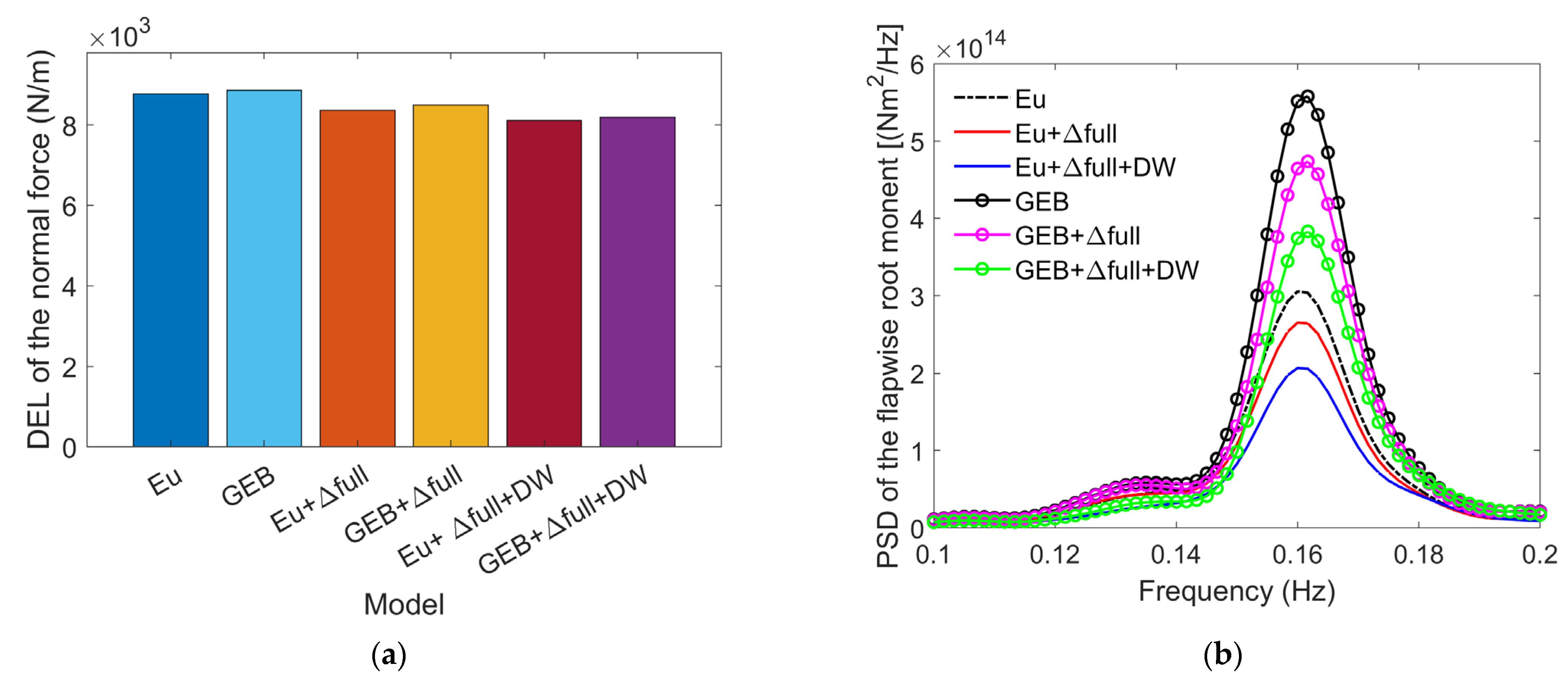
- The differences between the Eu and GEB model results characterize the fatigue load differences solely by structural nonlinearity effects. The relative differences between the EU and GEB model results in Table 2 indicate that, throughout the lifetime of the wind turbine, the Euler beam model calculates fatigue loads that are smaller than those generated by the GEB model in all three directions. The largest difference was obtained for the DEL of the torsional root load; the value calculated by the Eu model was 51.97% less than that generated by the GEB model. The DELs of the flapwise and edgewise root bending moments obtained by the Euler beam model were 7.16% less than those calculated by the GEB model. These differences demonstrate that the linear structural model tends to underestimate fatigue loads.
- (4)
- The differences between the Eu + Δfull + DW and GEB + Δfull + DW models can characterize the variations in the fatigue loads that result from the combined wind turbine structural nonlinearity, blade deformation, and dynamic wake effects; accounting for these effects allows the simulations to align more closely with practical considerations. These relative differences are presented in the last column of Table 2, and they indicate that when accounting for the dynamic wake, the Euler beam model calculated a torsional fatigue load that was 54.49% less than that produced by the GE model, while the calculated flapwise and edgewise loads were 8.24% and 7.26% smaller, respectively. Furthermore, a comparison of the sixth and third columns reveals that including the dynamic wake effects amplifies the differences in the fatigue loads caused by the structural nonlinearity effects.
4. Conclusions
- (1)
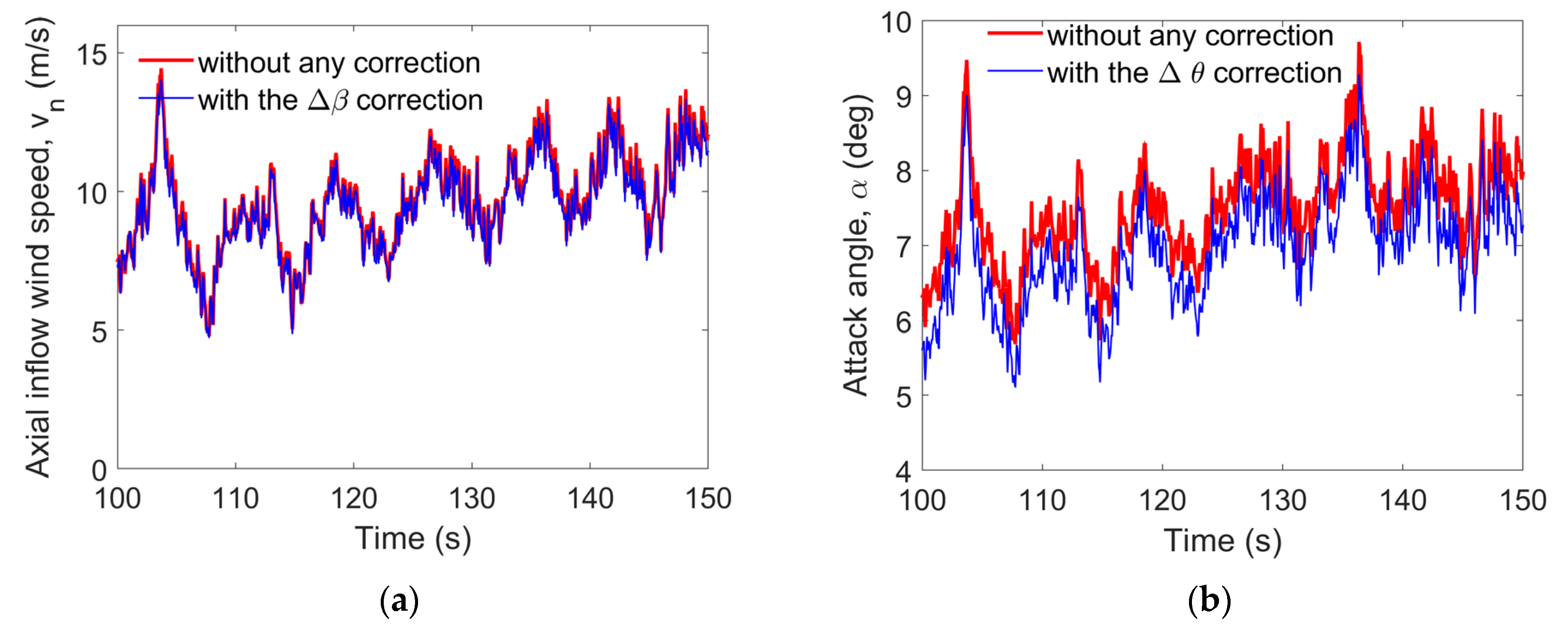
- A comparison with two commercial wind turbine simulation software packages demonstrated that the aeroelastic simulation model developed during this study is reliable. The GE-BEM model established during this study more accurately calculates the wind velocity at the blade elements, thereby bringing the simulation results closer to reality.
- (2)
- When a wind turbine operates near the rated wind speed, the flapwise deformation of the blades is at a maximum, and this deformation has the greatest impact on the aerodynamic loads. When a blade operates at high wind speeds, however (near the cut-out wind speed), the torsional vibration of the blade most significantly affects the aerodynamic loads.
- (3)
- Flapwise deformation of a turbine blade reduces the blade loads, while torsional deformation of the blade decreases the blade loads at low wind speeds but increases them at high wind speeds.
- (4)
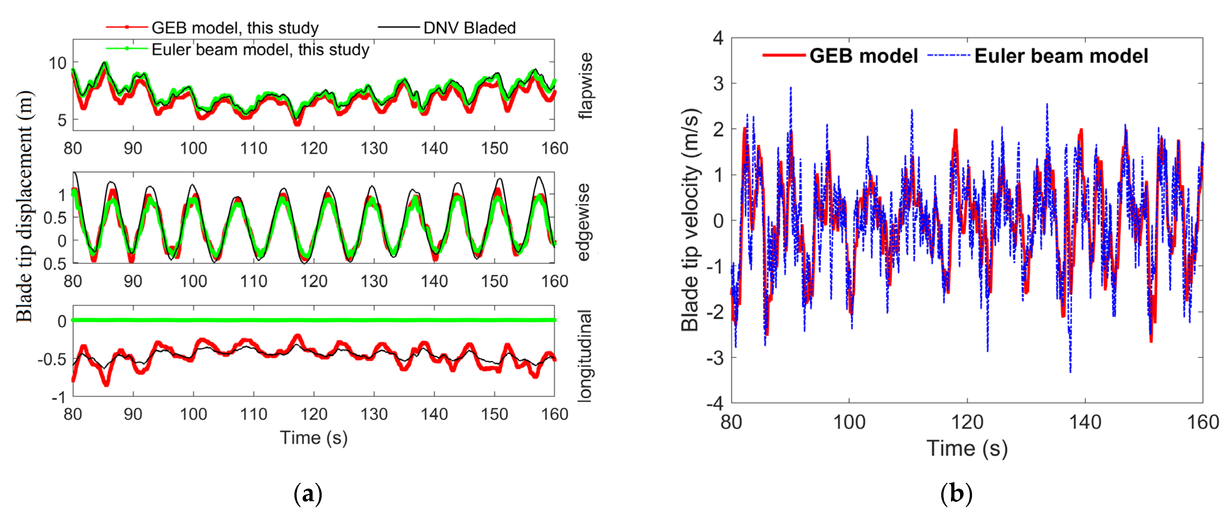
- Due to the overestimation of both the blade deformation and the vibration speed by the Euler beam model, and consequently the overestimation of feedback to the aerodynamic model, the blade loads are underestimated by this model. The difference between DEL values calculated by the Euler beam model and the GEB model developed during this study was largest in the torsional root direction, with a maximum deviation of 53.5%.
Author Contributions
Funding
Institutional Review Board Statement
Informed Consent Statement
Data Availability Statement
Acknowledgments
Conflicts of Interest
References
- Jahani, K.; Langlois, R.G.; Afagh, F.F. Structural Dynamics of Offshore Wind Turbines: A Review. Ocean Eng. 2022, 251, 111136. [Google Scholar] [CrossRef]
- Wind Energy in Europe: 2023 Statistics and the Outlook for 2024–2030. WindEurope. Available online: https://windeurope.org/intelligence-platform/product/wind-energy-in-europe-2023-statistics-and-the-outlook-for-2024-2030/#overview (accessed on 4 March 2024).
- World’s Largest Single Capacity Offshore Wind Turbine Successfully Installed—Global Times. Available online: https://www.globaltimes.cn/page/202306/1293347.shtml (accessed on 23 November 2023).
- World’s Largest 18 MW Offshore Wind Turbine Rolls off Assembly Line—CGTN. Available online: https://news.cgtn.com/news/2023-11-12/World-s-largest-18-MW-offshore-wind-turbine-rolls-off-assembly-line-1oFWaJ9ZQnm/index.html (accessed on 23 November 2023).
- Igwemezie, V.; Mehmanparast, A.; Kolios, A. Current Trend in Offshore Wind Energy Sector and Material Requirements for Fatigue Resistance Improvement in Large Wind Turbine Support Structures—A Review. Renew. Sustain. Energy Rev. 2019, 101, 181–196. [Google Scholar] [CrossRef]
- Soares-Ramos, E.P.P.; de Oliveira-Assis, L.; Sarrias-Mena, R.; Fernández-Ramírez, L.M. Current Status and Future Trends of Offshore Wind Power in Europe. Energy 2020, 202, 117787. [Google Scholar] [CrossRef]
- Manolas, D.I.; Riziotis, V.A.; Voutsinas, S.G. Assessing the Importance of Geometric Nonlinear Effects in the Prediction of Wind Turbine Blade Loads. J. Comput. Nonlinear Dyn. 2015, 10, 041008. [Google Scholar] [CrossRef]
- Griffith, D.T.; Ashwill, T.D. The Sandia 100-Meter All-Glass Baseline Wind Turbine Blade: SNL100-00; Sandia National Laboratories: Albuquerque, Mexico, 2011. [Google Scholar]
- Wang, L.; Liu, X.; Renevier, N.; Stables, M.; Hall, G.M. Nonlinear Aeroelastic Modelling for Wind Turbine Blades Based on Blade Element Momentum Theory and Geometrically Exact Beam Theory. Energy 2014, 76, 487–501. [Google Scholar] [CrossRef]
- Wang, X.; Cai, C.; Cai, S.-G.; Wang, T.; Wang, Z.; Song, J.; Rong, X.; Li, Q. A Review of Aerodynamic and Wake Characteristics of Floating Offshore Wind Turbines. Renew. Sustain. Energy Rev. 2023, 175, 113144. [Google Scholar] [CrossRef]
- Ahlström, A. Influence of Wind Turbine Flexibility on Loads and Power Production. Wind Energy 2006, 9, 237–249. [Google Scholar] [CrossRef]
- Liu, X.; Lu, C.; Liang, S.; Godbole, A.; Chen, Y. Vibration-Induced Aerodynamic Loads on Large Horizontal Axis Wind Turbine Blades. Appl. Energy 2017, 185, 1109–1119. [Google Scholar] [CrossRef]
- Wang, L.; Liu, X.; Kolios, A. State of the Art in the Aeroelasticity of Wind Turbine Blades: Aeroelastic Modelling. Renew. Sustain. Energy Rev. 2016, 64, 195–210. [Google Scholar] [CrossRef]
- Dai, J.; Li, M.; Chen, H.; He, T.; Zhang, F. Progress and Challenges on Blade Load Research of Large-Scale Wind Turbines. J. Dai 2022, 196, 482–496. [Google Scholar] [CrossRef]
- Zhong, W.; Shen, W.Z.; Wang, T.G.; Zhu, W.J. A New Method of Determination of the Angle of Attack on Rotating Wind Turbine Blades. Energies 2019, 12, 4012. [Google Scholar] [CrossRef]
- Sun, Z.; Chen, J.; Shen, W.Z.; Zhu, W.J. Improved Blade Element Momentum Theory for Wind Turbine Aerodynamic Computations. Renew. Energy 2016, 96, 824–831. [Google Scholar] [CrossRef]
- Fritz, E.K.; Ferreira, C.; Boorsma, K. An Efficient Blade Sweep Correction Model for Blade Element Momentum Theory. Wind Energy 2022, 25, 1977–1994. [Google Scholar] [CrossRef]
- Sayed, M.; Klein, L.; Lutz, T.; Krämer, E. The Impact of the Aerodynamic Model Fidelity on the Aeroelastic Response of a Multi-Megawatt Wind Turbine. Renew. Energy 2019, 140, 304–318. [Google Scholar] [CrossRef]
- Rezaei, M.M.; Behzad, M.; Haddadpour, H.; Moradi, H. Development of a Reduced Order Model for Nonlinear Analysis of the Wind Turbine Blade Dynamics. Renew. Energy 2015, 76, 264–282. [Google Scholar] [CrossRef]
- Zhang, P.; Huang, S. Review of Aeroelasticity for Wind Turbine: Current Status, Research Focus and Future Perspectives. Front. Energy 2011, 5, 419–434. [Google Scholar] [CrossRef]
- Rafiee, R.; Tahani, M.; Moradi, M. Simulation of Aeroelastic Behavior in a Composite Wind Turbine Blade. J. Wind Eng. Ind. Aerodyn. 2016, 151, 60–69. [Google Scholar] [CrossRef]
- Della Posta, G.; Leonardi, S.; Bernardini, M. A Two-Way Coupling Method for the Study of Aeroelastic Effects in Large Wind Turbines. Renew. Energy 2022, 190, 971–992. [Google Scholar] [CrossRef]
- Mo, W.; Li, D.; Wang, X.; Zhong, C. Aeroelastic Coupling Analysis of the Flexible Blade of a Wind Turbine. Energy 2015, 89, 1001–1009. [Google Scholar] [CrossRef]
- Sabale, A.; Gopal, K.V.N. Nonlinear Aeroelastic Response of Wind Turbines Using Simo-Vu-Quoc Rods. Appl. Math. Model. 2019, 65, 696–716. [Google Scholar] [CrossRef]
- Panteli, A.N.; Manolas, D.I.; Riziotis, V.A.; Spiliopoulos, K.V. Comparative Study of Two Geometrically Non-Linear Beam Approaches for the Coupled Wind Turbine System. J. Wind Eng. Ind. Aerodyn. 2022, 231, 105231. [Google Scholar] [CrossRef]
- Finnegan, W.; Jiang, Y.; Dumergue, N.; Davies, P.; Goggins, J. Investigation and Validation of Numerical Models for Composite Wind Turbine Blades. J. Mar. Sci. Eng. 2021, 9, 525. [Google Scholar] [CrossRef]
- Sayed, M.; Lutz, T.; Krämer, E.; Shayegan, S.; Wüchner, R. Aeroelastic Analysis of 10 MW Wind Turbine Using CFD–CSD Explicit FSI-Coupling Approach. J. Fluids Struct. 2019, 87, 354–377. [Google Scholar] [CrossRef]
- Fan, Q.; Wang, X.; Yuan, J.; Liu, X.; Hu, H.; Lin, P. A Review of the Development of Key Technologies for Offshore Wind Power in China. J. Mar. Sci. Eng. 2022, 10, 929. [Google Scholar] [CrossRef]
- Argyris, J. An Excursion into Large Rotations. Comput. Methods Appl. Mech. Eng. 1982, 32, 85–155. [Google Scholar] [CrossRef]
- Reissner, E. On One-Dimensional Finite-Strain Beam Theory: The Plane Problem. Z. Angew. Math. Phys. ZAMP 1972, 23, 795–804. [Google Scholar] [CrossRef]
- Simo, J.C.; Vu-Quoc, L. On the Dynamics of Flexible Beams Under Large Overall Motions—The Plane Case: Part II. J. Appl. Mech. 1986, 53, 855–863. [Google Scholar] [CrossRef]
- Simo, J.C. A Finite Strain Beam Formulation. The Three-Dimensional Dynamic Problem. Part I. Comput. Methods Appl. Mech. Eng. 1985, 49, 55–70. [Google Scholar] [CrossRef]
- Simo, J.C.; Vu-Quoc, L. A Three-Dimensional Finite-Strain Rod Model. Part II: Computational Aspects. Comput. Methods Appl. Mech. Eng. 1986, 58, 79–116. [Google Scholar] [CrossRef]
- Cardona, A.; Geradin, M. A Beam Finite Element Non-linear Theory with Finite Rotations. Numer. Meth Eng. 1988, 26, 2403–2438. [Google Scholar] [CrossRef]
- Hilber, H.M.; Hughes, T.J.R.; Taylor, R.L. Improved Numerical Dissipation for Time Integration Algorithms in Structural Dynamics. Earthq. Eng. Struct. Dyn. 1977, 5, 283–292. [Google Scholar] [CrossRef]
- Chung, J.; Hulbert, G. A Time Integration Algorithm for Structural Dynamics with Improved Numerical Dissipation: The Generalized-α Method. ASME J. Appl. Mech. 1993, 60, 371–375. [Google Scholar] [CrossRef]
- Hansen, M.O.L. Aerodynamics of Wind Turbines, 3rd ed.; Earthscan from Routledge: London, UK, 2015; ISBN 978-1-138-77507-7. [Google Scholar]
- Bak, C.; Zahle, F.; Bitsche, R.; Kim, T.; Yde, A.; Henriksen, L.C.; Hansen, M.H.; Blasques, J.P.A.A.; Gaunaa, M.; Natarajan, A. The DTU 10-MW Reference Wind Turbine. DTU Wind Energy Report-I-0092. In Danish Wind Power Research. 2013. Available online: https://backend.orbit.dtu.dk/ws/portalfiles/portal/55645274/The_DTU_10MW_Reference_Turbine_Christian_Bak.pdf (accessed on 19 March 2024).
- Pitt, D.M.; Peters, D.A. Theoretical Prediction of Dynamic-in Ow Derivatives; University of Bristol: Bristol, UK, 1981. [Google Scholar]
- Wang, Q.; Sprague, M.A.; Jonkman, J.; Johnson, N.; Jonkman, B. BeamDyn: A High-fidelity Wind Turbine Blade Solver in the FAST Modular Framework. Wind Energy 2017, 20, 1439–1462. [Google Scholar] [CrossRef]
- Le, T.-N.; Battini, J.-M.; Hjiaj, M. Dynamics of 3D Beam Elements in a Corotational Context: A Comparative Study of Established and New Formulations. Finite Elem. Anal. Des. 2012, 61, 97–111. [Google Scholar] [CrossRef]
- Bossanyi, E. GH Bladed Theory Manual; GH & Partners Ltd.: New Barnet, Hertfordshire, UK, 2003. [Google Scholar]
- Miner, M.A. Cumulative damage in fatigue. J. Appl. Mech. 1945, 67, A159–A164. [Google Scholar] [CrossRef]
- Lloyd, G.; Hamburg, G. Guideline for the Certification of Offshore Wind Turbines 2005; Germanischer Lloyd Wind Energie GmbH: Hamburg, Germany, 2005. [Google Scholar]
- Lee, Y.-L. (Ed.) Fatigue Testing and Analysis: Theory and Practice; Elsevier Butterworth-Heinemann: Amsterdam, The Netherlands; ISBN 978-0-7506-7719-6.
- IEC 61400-1; Wind Turbines—Part 1: Design Requirements (3rd ed.). International Electrotechnical Commission: London, UK, 2005.

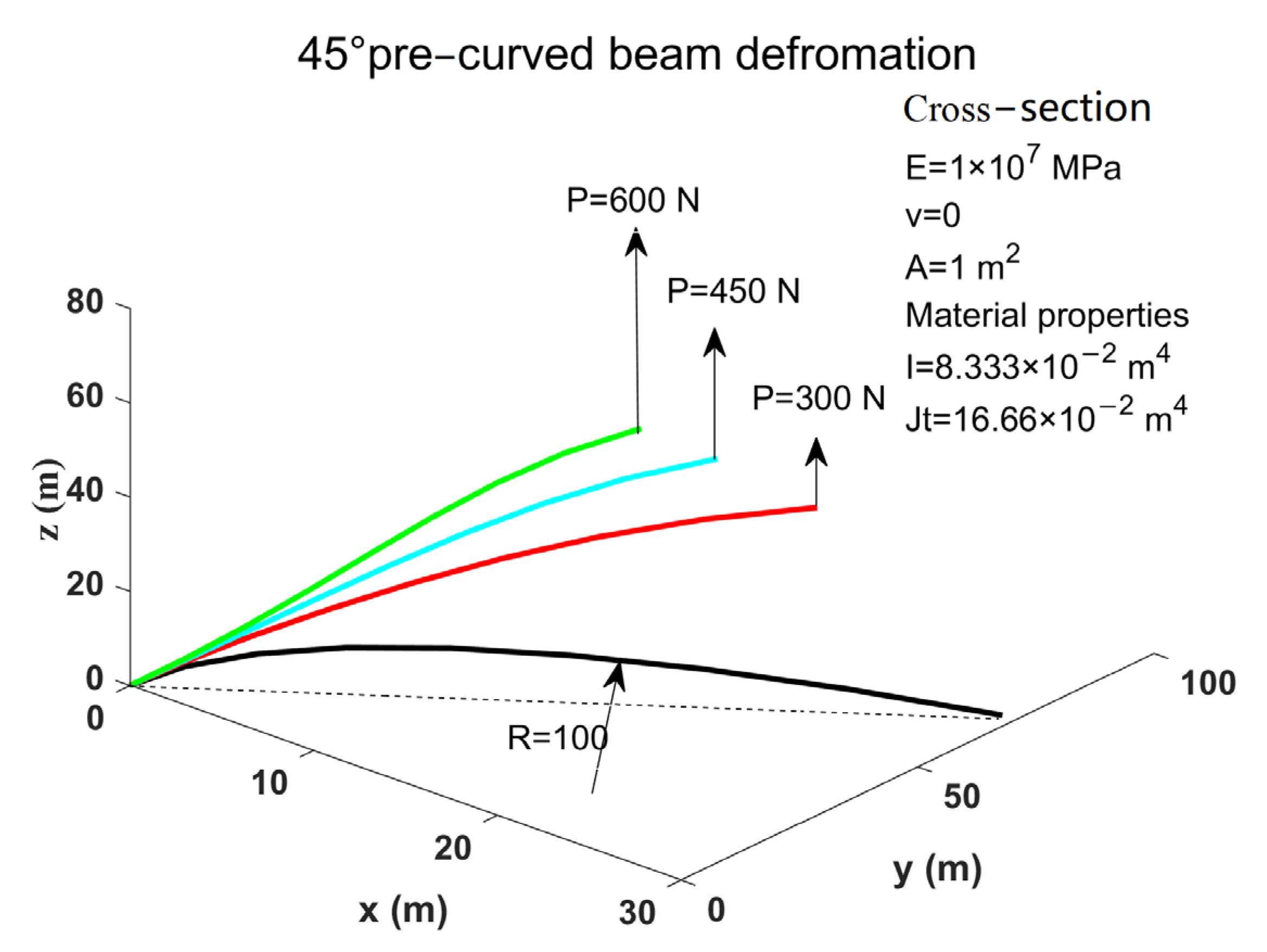



| Load | Position Calculated during This Study, (x1, x2, x3) (m) | Cardona and Geradin [34], (x1, x2, x3) (m) | Simo and Vu-Quoc [31], (x1, x2, x3) (m) | Rotation Vector, Ψ |
|---|---|---|---|---|
| 300 N | (22.26, 58.88, 40.08) | (22.14, 58.64, 40.35) | (22.33, 58.84, 40.08) | (0.72, −0.49, 0.02) |
| 450 N | (18.40, 52.27, 48.40) | (18.38, 52.11, 48.59) | (18.62, 52.32, 48.39) | (0.91, −0.50, 0.04) |
| 600 N | (15.67, 47.30, 53.37) | (15.55, 47.04, 53.50) | (15.79, 47.23, 53.37) | (1.03, −0.55, 0.05) |
| Model | GEB | EU | GEB + Δfull | GEB + Δfull + DW | Eu + Δfull + DW |
|---|---|---|---|---|---|
| Reference model | DEL (kNm) | GEB | GEB | GEB | GEB + Δfull + DW |
| Relative difference | diff (%) | diff (%) | diff (%) | diff (%) | |
| Flapwise root moment | 35,192 | −7.16 | −1.88 | 0.88 | −8.24 |
| Edgewise root moment | 29,166 | −7.19 | −0.14 | −0.61 | −7.26 |
| Torsional root moment | 330 | −5.97 | 5.73 | 7.92 | −54.49 |
Disclaimer/Publisher’s Note: The statements, opinions and data contained in all publications are solely those of the individual author(s) and contributor(s) and not of MDPI and/or the editor(s). MDPI and/or the editor(s) disclaim responsibility for any injury to people or property resulting from any ideas, methods, instructions or products referred to in the content. |
© 2024 by the authors. Licensee MDPI, Basel, Switzerland. This article is an open access article distributed under the terms and conditions of the Creative Commons Attribution (CC BY) license (https://creativecommons.org/licenses/by/4.0/).
Share and Cite
Ma, X.; Peng, X.; Sun, J.; Chen, Y.; Huang, Z. A Comprehensive Investigation of Linear and Nonlinear Beam Models on Flexible Wind Turbine Blade Load Calculations. J. Mar. Sci. Eng. 2024, 12, 548. https://doi.org/10.3390/jmse12040548
Ma X, Peng X, Sun J, Chen Y, Huang Z. A Comprehensive Investigation of Linear and Nonlinear Beam Models on Flexible Wind Turbine Blade Load Calculations. Journal of Marine Science and Engineering. 2024; 12(4):548. https://doi.org/10.3390/jmse12040548
Chicago/Turabian StyleMa, Xinwen, Xianghua Peng, Jingwei Sun, Yan Chen, and Zhihong Huang. 2024. "A Comprehensive Investigation of Linear and Nonlinear Beam Models on Flexible Wind Turbine Blade Load Calculations" Journal of Marine Science and Engineering 12, no. 4: 548. https://doi.org/10.3390/jmse12040548
APA StyleMa, X., Peng, X., Sun, J., Chen, Y., & Huang, Z. (2024). A Comprehensive Investigation of Linear and Nonlinear Beam Models on Flexible Wind Turbine Blade Load Calculations. Journal of Marine Science and Engineering, 12(4), 548. https://doi.org/10.3390/jmse12040548


