Article

Dynamic Projection Method of Electronic Navigational Charts for Polar Navigation

1
School of Geodesy and Geomatics, Wuhan University, Wuhan 430079, China
2
College of Electrical Engineering, Naval University of Engineering, Wuhan 430033, China
*
Author to whom correspondence should be addressed.
J. Mar. Sci. Eng. 2024, 12(4), 577; https://doi.org/10.3390/jmse12040577
Submission received: 6 March 2024 / Revised: 27 March 2024 / Accepted: 27 March 2024 / Published: 28 March 2024

Abstract

:
Electronic navigational charts (ENCs) are geospatial databases compiled in strict accordance with the technical specifications of the International Hydrographic Organization (IHO). Electronic Chart Display and Information System (ECDIS) is a Geographic Information System (GIS) operated by ENCs for real-time navigation at sea, which is one of the key technologies for intelligent ships to realize autonomous navigation, intelligent decision-making, and other functions. Facing the urgent demand for high-precision and real-time nautical chart products for polar navigation under the new situation, the projection of ENCs for polar navigation is systematically analyzed in this paper. Based on the theory of complex functions, we derive direct transformations of Mercator projection, polar Gauss-Krüger projection, and polar stereographic projection. A rational set of dynamic projection options oriented towards polar navigation is proposed with reference to existing specifications for the compilation of the ENCs. From the perspective of nautical users, rather than the GIS expert or professional cartographer, an ENCs visualization idea based on multithread-double buffering is integrated into Polar Region Electronic Navigational Charts software, which effectively solves the problem of large projection distortion in polar navigation applications. Taking the CGCS2000 reference ellipsoid as an example, the numerical analysis shows that the length distortion of the Mercator projection is less than 10% in the region up to 74°, but it is more than 80% at very high latitudes. The maximum distortion of the polar Gauss-Krüger projection does not exceed 10%. The degree of distortion of the polar stereographic projection is less than 1% above 79°. In addition, the computational errors of the direct conversion formulas do not exceed 1 0 9 m throughout the Arctic range. From the point of view of the computational efficiency of the direct conversion model, it takes no more than 0.1 s to compute nearly 8 million points at 1 × 1 resolution, which fully meets the demand for real-time nautical chart products under information technology conditions.

1. Introduction

With global warming causing the rapid melting of polar sea ice, the significance of the Arctic region in shipping, energy, and security has been increasingly highlighted. The Arctic route is poised to become the new major maritime artery [1,2,3,4]. Currently, there are several challenges in polar navigation, including rapidly changing marine environments, limited communication capabilities, and inadequate navigation safety measures [5,6,7]. There are potential risks associated with ships exploring the Arctic, such as the occurrence of extreme events, such as ship collisions leading to oil spills [8,9]. Hence, to ensure safe navigation or operations in polar regions, vessels must rely on high-precision charts as essential information support, which makes polar charts indispensable, serving as a key prerequisite for the realization of polar navigation and resource development. However, when encountering the unique environment of polar regions, the common Electronic Chart Display and Information System (ECDIS) based on true heading reference is not fully applicable, which could cause systemic problems in navigation parameter definitions, piloting, positioning, and calculations [10,11]. Among them, choosing the projection method for charts is a fundamental issue that urgently needs to be solved [12,13].
The projection of ENCs forms the cornerstone of research in navigation applications. The presentation of navigational information, the characteristics of navigational errors, and the implementation of navigational methodologies are determined. Since the middle of the 20th century, extensive research has been carried out on polar nautical charting by map cartographers such as Beresford, Snyder, Pearson, Smith, and others [14,15,16,17,18]. The availability of the modified Lambert projection, Gauss-Krüger projection, gnomonic projection, polar spherical projection, and azimuthal equidistant projection has been analyzed. With the development of ECDIS, the study of polar chart projection has entered a new stage. The projection to be used for Electronic Navigational Charts (ENCs) was the focus of [19,20]. However, the current international standards do not provide specific requirements for map projection to be used in ENCs and ECDIS. The choice of projection is still up to the manufacturer, which leads to different systems using different methods and creating different problems. Based on the existing literature [15,16], it is considered that the development of a computer-based method for the projection of ENCs for polar navigation should satisfy the following conditions:
  • Conformal projection, in order to facilitate angle measurements and pilotage.
  • Length and area distortions are kept as small as possible, in order to facilitate accurate measurement of distance and area measurements.
  • The grid lines of latitude and longitude should be simple, in order to facilitate the construction of grids and the measurement of headings.
  • Great circle routes should be as straight as possible, in order to facilitate navigation along them.
Therefore, Mercator projection, polar Gauss-Krüger projection, and polar stereographic projection are selected as projections that can be used for ENCs in the polar region. The Mercator projection is commonly used in low- and mid-latitude charts [21]. Furthermore, a mature set of marine navigation techniques based on the Mercator projection has been developed, which is in line with the charting habits of mariners, but the projection has a large deformation in the polar region [22]. The polar Gauss-Krüger projection is divided into 3 or 6 zones [23], making it difficult to be fully represented. The existing studies related to polar stereographic projection are based on the sphere [24]. However, the high-precision earth model is a rotating ellipsoid, and inherent principle errors are inevitably present in the projections based on the sphere model when navigating in the polar region.
Aiming at the problem of large distortion of the Mercator projection in the polar region, the selection of an appropriate reference latitude or mapping area in order to reasonably control the degree of distortion has been proposed by scholars [25], which makes it possible to follow the Mercator projection within a certain range of distortion. To address the problem of the poor availability of the Gauss-Krüger projection in the polar region, Bowring, using the inherent connection between complex (variable) functions and conformal mapping, derived the formula for the transverse Mercator projection without zones [26]. With the help of a computer algebra system, Shaofeng Bian provided formulas for the Gauss-Krüger projection complex function without band splitting, and the complex function expressions of scale ratio and meridian convergence angle were derived [27,28]. The non-iterative formulas of forward and inverse solutions of the Gauss-Krüger projection based on Lee’s formula were derived by Jiachun Guo [29]. To some extent, the difficulty of applying the traditional Gauss-Krüger projection has been solved by the introduction of the complex function. In most cases, polar stereographic projection has been studied based on the sphere. Drawing on the method established by the ellipsoidal sundial projection formula, the double polar stereographic projection was proposed by Chaojiang Wen [30]. That is, the ellipsoidal surface is first conformally projected onto a suitable transition sphere, and then that sphere is projected onto the plane in the manner of polar stereographic projection.
All of the above solutions effectively address the shortcomings of the three projections in practice to a certain extent. Nevertheless, in navigation, nature entails a process of constant position change, especially in marine navigation. The use of a single projection makes it often difficult to meet the accuracy requirements of map representation, and it is necessary to design an adaptive map projection according to the specific characteristics of the navigation to satisfy the needs of high-precision and high-reliability applications in polar navigation [31,32,33,34]. In addition to this, how to make the map visualization system better meet the needs of the users and ensure its more effective utilization is also an issue that needs to be put into focus.
Therefore, in order to improve the accuracy of map representation in navigation applications, this paper introduces complex functions, considering their unique role and obvious advantages in conformal transformation. On the basis of existing research, complex function expressions for three projections are given, and direct conversion formulas based on the complex functions of these three projections are derived. In addition, a dynamic projection of the ENCs oriented towards polar navigation is proposed, the conversion accuracy and efficiency of the three projections are analyzed, and a visualization algorithm based on multithread-double buffer is designed. The results show that the constructed dynamic projection method of the ENCs for polar navigation can improve the accuracy of map expression in polar navigation applications and can provide a reference for the compilation and application of high-precision polar electronic nautical charts.
This article is organized as follows. Section 2 includes the complex function expression of the conformal projection of a polar chart based on the ellipsoid. In Section 3, a design approach to the dynamic projection of the ENCs is presented. In Section 4, the distortions and their availability within each latitude band are elaborated, the most suitable navigation-oriented projections within that range are given, and the transformations between the different projections are analyzed. Section 5 presents a visualization idea for an ENC-based multithread-double buffer, and Section 6 discusses the results of the analysis, followed by the conclusions.

2. Complex Function Expression of Conformal Projection of Polar Charts Based on the Ellipsoid

2.1. Mercator Projection Coordinates in Complex Form

According to the general formula for normal cylindrical projection, combined with the properties of complex functions, the complex function expression for the forward solution of the Mercator projection is as follows:
z 1 = x 1 + i y 1 = r 0 w
In Formula (1), z 1 represents the Mercator projection complex coordinates; x 1 is the ordinate, which is the southbound coordinate; and y 1 represents the abscissa, that is, the east coordinate. w = q + i l is the expression for isometric latitude in the field of complex functions, where q is the isometric latitude, corresponding to the expression of geodetic latitude B, and l is the longitude difference. In addition, r 0 = a c o s B 0 1 e 2 sin 2 B 0 represents the cylindrical radius, a represents the semi-major axis of the ellipsoid, and B 0 refers to the reference latitude.
The simple shape of the latitude and longitude gridlines of the Mercator projection makes it easy to map and calculate. In addition, rhumb lines are projected as straight lines, which allows marine navigation users to visualize the shape and direction of the routes when planning the routes, so that accurate navigation can be carried out. Hence, the Mercator projection is the most commonly used method in nautical charts. However, the large distortion at high latitudes becomes a major factor limiting the application of Mercator projection in the polar regions.
The expression for the complex function of the inverse solution of the Mercator projection is obtained by a slight change in Equation (1):
w = q + i l = x 1 + i y 1 r 0
The Mercator projection is a conformal projection, meaning that the angles are not distorted. The scale distortion u 1 of the secant Mercator projection at the reference latitude B 0 and latitude B can be expressed as follows, where e represents the first eccentricity:
u 1 = cos B 0 cos B 1 e 2 s i n 2 B 1 e 2 s i n 2 B 0 1
It is clear that the secant projection is a similar variation to the tangent projection in the theoretical study of map projections. The scale factor of the Mercator projection can be determined by the reference latitude. According to a previous report [35], the reference latitude is generally determined by minimizing the distortion at the maximum deformation, with the purpose of reducing the distortion and making the deformation uniformly distributed in the region. B 0 is given by B - = B N + B S 2 and Δ B = B N B S 2 , with B N and B S being the southern and northern latitudes of the region, respectively:
B 0 = B - + 12 ( 4 7 e 2 ) cos B - e 2 cos 2 B - cos 3 B - 2 cos 4 B - 8 sin 2 B - Δ B 2

2.2. Polar Gauss-Krüger Projection Coordinates in Complex Form

According to the literature [36], the expression of the complex function of the non-singular polar Gauss-Krüger projection for the forward solution in the polar region is given below:
z 2 = x 2 + i y 2 = a α 0 θ + a k = 1 5 ( 1 ) k 1 α 2 k sin 2 k θ
Similarly, a sketch of the Gauss-Krüger projection is drawn in Geocart, as shown in Figure 1.
Given that power series expressions based on the third flattening n have a more compact form and better convergence [37,38], the coefficients can be expressed in terms of n as follows:
α 0 = 1 + n 5 4 n 2 + 5 4 n 3 81 64 n 4 + 81 64 n 5 α 2 = 1 2 n 7 6 n 2 + 77 48 n 3 1111 720 n 4 + 2281 1920 n 5 α 4 = 13 48 n 2 209 240 n 3 + 3817 2880 n 4 6917 6720 n 5 α 6 = 61 240 n 3 1663 1680 n 4 + 14459 8960 n 5 α 8 = 49561 161280 n 4 221401 161280 n 5 α 10 = 34729 80640 n 5
In the polar Gauss-Krüger projection plane, z 2 represents the polar Gauss-Krüger projection complex coordinates and x 2 , y 2 are the ordinate and abscissa, respectively. In order to eliminate singularities near the poles, the conformal co-latitude θ = 2 arctan exp w is introduced. Two points need to be noted. One is that the coefficients of the expression in this paper are slightly different from those in the literature [36], which is due to the fact that the origin of the expression is moved to the pole for ease of mapping in the Arctic. The other is that Re sin k z = sin k x cosh k y and Im sin k z = cos k x sinh k y . These equalities hold for any complex number z = x + i y and any natural number k 1 [39].
We obtain the expression for the complex function of the inverse solution by using the symbolic iteration method:
w = z 2 a α 0 = x 2 + i y 2 a α 0 θ = w + k = 1 5 b 2 k sin 2 k w
The coefficients in Equation (6) are expended in terms of n up to n 5 :
b 2 = 1 2 n 2 3 n 2 + 37 96 n 3 1 360 n 4 81 512 n 5 b 4 = 1 48 n 2 1 15 n 3 + 437 1440 n 4 46 105 n 5 b 6 = 17 480 n 3 37 840 n 4 209 4480 n 5 b 8 = 4397 161280 n 4 + 11 504 n 5 b 10 = 4583 161280 n 5
A clerical error in the inverse solution coefficients b 2 and b 8 ,   a s   p r e s e n t e d   i n the literature [36], is corrected here.
Additionally, the angle of the polar Gauss-Krüger projection is not distorted. The length distortion u 2 can be calculated as the derivative of the coordinate z 2 at a specific point.
u 2 = z 2 1 = 1 e 2 sin 2 B 1 / 2 sin θ α 0 k = 1 5 2 k α 2 k cos 2 k θ cos B 1
The Universal Transverse Mercator Projection (UTM) is a Gauss-Krüger projection with a central meridian projection length ratio of 0.9996.

2.3. Polar Stereographic Projection Coordinates in Complex Form

According to the general formula for azimuthal conformal projection, the complex function expression for the forward solution of the double polar stereographic projection is as follows:
u 2 = z 2 1 = 1 e 2 sin 2 B 1 / 2 sin θ α 0 k = 1 5 2 k α 2 k cos 2 k θ cos B 1
In Formula (8), z 3 is defined as stereographic projection complex coordinates, x 3 , y 3 are the ordinate and abscissa, respectively, φ 0 stands for equiangular reference latitude. Normally, the conformal spherical radius is considered as R φ ( π 2 ) = a 1 e 2 1 e 1 + e e / 2 . The Universal Polar Stereographic Projection (UPS) is a polar stereographic projection for φ 0 = 8 1 06 25 . 3 .
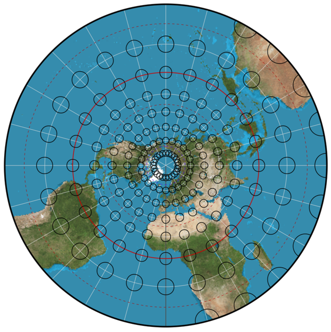
Moreover, a sketch of the polar stereographic projection is drawn in Geocartv3.2.0, as shown in Figure 2.
We obtain the complex function expression for the inverse solution of the double polar stereographic projection from Equation (8):
exp w = sec 2 π 4 φ 0 2 2 R φ ( x 3 + i y 3 )
Since the double polar stereographic projection is a conformal projection, the angular distortion is 0. The length distortion u 3 is related to the geodetic latitude B and the conformal reference latitude φ 0 , independent of the longitude difference l , which can be expressed as follows [25]:
u 3 = 2 cos 2 π 4 φ 0 2 1 e 2 sin 2 B 1 e 2 1 + sin B 1 e 1 + e 1 + e sin B 1 e sin B e 2 1

3. Method Design for Dynamic Chart Projection

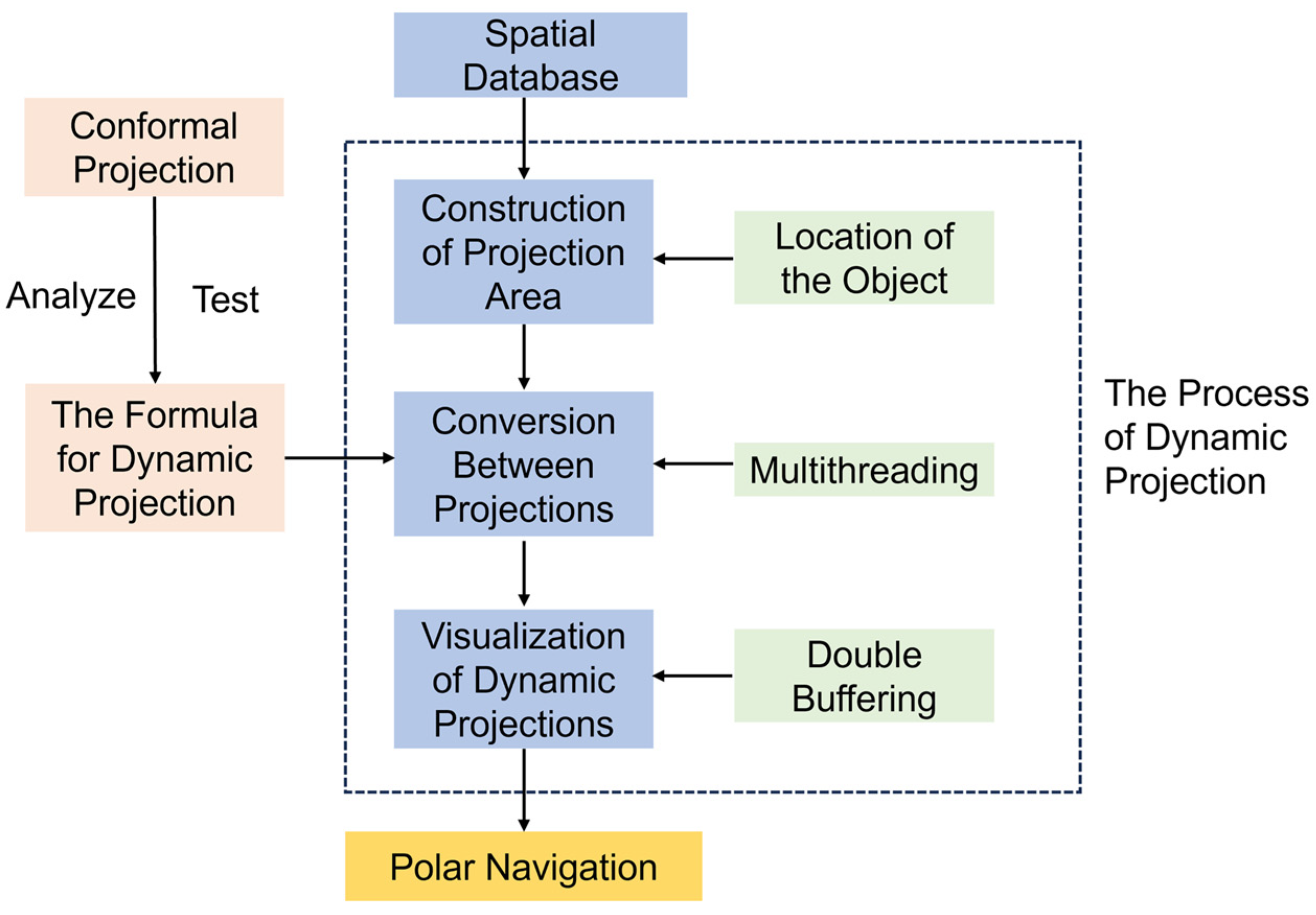
The core objective of polar dynamic chart projection is to accurately represent maps in navigation applications by adopting suitable projection methods. Therefore, the design of the projection is key. In addition, solving problems based on trajectory points in real time is crucial. The specific method of dynamic chart projection designed in this paper is as follows: firstly, the inverse operation is carried out to calculate the latitude and longitude according to the inverse solution expressions of the three projections, and then the latitude and longitude are converted to plane coordinates according to the forward solution expressions. The essence of the dynamic projection is the transformation between different projections. At present, the numerical transformation method and indirect transformation method are mainly used for the translation between different projections under the ellipsoid model [40]. However, these methods are more complicated and inefficient in the calculation process, and both of them fail to establish a direct transformation between the projected coordinates. Therefore, the formulas for the direct conversion of the projections in this section are derived for fast visualization in the ENCs of the polar region.

3.1. Transformation between Mercator Projection and Polar Gauss-Krüger Projection

The Mercator projection coordinates x 1 , y 1 are substituted into the complex function expression for the inverse solution of the Mercator projection (Equation (2)) to obtain the latitude and longitude coordinates. Subsequently, it is substituted into the complex function expression of the forward solution of polar Gauss-Krüger projection (Equation (5)), to obtain the complex function expression of the Mercator projection transformed to polar Gauss-Krüger projection as follows:
θ = 2 arctan e x p ( x 1 + i y 1 r 0 ) z 2 = x 2 + i y 2 = a α 0 θ + a k = 1 5 ( 1 ) k 1 α 2 k sin 2 k θ
The polar Gauss-Krüger projection coordinates x 2 , y 2 are known. The latitude and longitude coordinates are obtained by substituting into Formula (6). Then, by substituting these coordinates into Formula (1), we obtain the expression of the complex function of the polar Gauss-Krüger projection transformed to the Mercator projection:
θ = x 2 + i y 2 a α 0 + k = 1 5 b 2 k sin 2 k ( x 2 + i y 2 ) a α 0 z 1 = x 1 + i y 1 = r 0 lntan θ 2
It should be noted that the central meridian of the two projections derived from Equations (11) and (12) should be the same, and if not, it should be corrected.

3.2. Transformation between Polar Gauss-Krüger Projection and Polar Stereographic Projection

Similarly, by substituting the polar Gauss-Krüger projection coordinates x 2 , y 2 into Equation (6) to obtain the latitude and longitude, and later substituting into the expression of the complex function of the forward solution of the polar stereographic projection (Equation (8)), we obtain the expression of the complex function of the Gauss-Krüger projection, transformed to the polar stereographic projection:
θ = x 2 + i y 2 a α 0 + k = 1 5 b 2 k sin 2 k ( x 2 + i y 2 ) a α 0 z 3 = x 3 + i y 3 = 2 R φ cos 2 ( π 4 φ 0 2 ) tan θ 2
Given the polar stereographic projection coordinates x 3 , y 3 , we obtain the latitude and longitude by inverse solution, and then substitute into Formula (5) to obtain the expression of the complex function of polar stereographic projection, transformed to polar Gauss-Krüger projection:
θ = 2 arctan sec 2 ( π 4 φ 0 2 ) 2 R φ x 3 + i y 3 z 2 = x 2 + i y 2 = a α 0 θ + a k = 1 5 ( 1 ) k 1 α 2 k sin 2 k θ

3.3. Transformation between Polar Gauss-Krüger Projection and Polar Stereographic Projection

We obtain the expression for the complex function of the Mercator projection transformed to polar stereographic projection by substituting x 1 , y 1 into Equation (2) and then into Equation (8):
z 3 = x 3 + i y 3 = 2 R φ cos 2 ( π 4 φ 0 2 ) e x p ( x 1 + i y 1 r 0 )
Substituting x 3 , y 3 into Formula (9) to get the latitude and longitude and then substituting into Formula (1), we can get the expression of the complex function of polar stereographic projection transformed to Mercator projection:
z 1 = x 1 + i y 1 = r 0 ln sec 2 ( π 4 φ 0 2 ) 2 R φ x 3 + i y 3

4. Evaluation of Dynamic Projection

With the help of Mathematica and MATLAB, the China Geodetic Coordinate System 2000 (CGCS2000) and the Arctic boundary data from the National Oceanic and Atmospheric Administration (NOAA, https://www.noaa.gov/, accessed on 26 March 2024) are taken as examples for the numerical analysis in this paper. We discuss and analyze the distortion of polar navigation projection from two aspects: length distortion and longitude and latitude grid line distortion, focusing on the distortion in each latitude segment of 66.5 ~ 7 0 , 70 ~ 7 5 , 75 ~8 0 , 80 ~8 5 , 85 ~ 9 0 . Availability is analyzed and the most suitable navigation-oriented projection type for that projection range is given. The transition between different projections is translated using the direct transformation formulas derived in Section 3, and the translation accuracy and efficiency are analyzed. The reference ellipsoid constants are a = 6   378   137   m and f = 1 / 298.257   222   101 .

4.1. Length Distortion

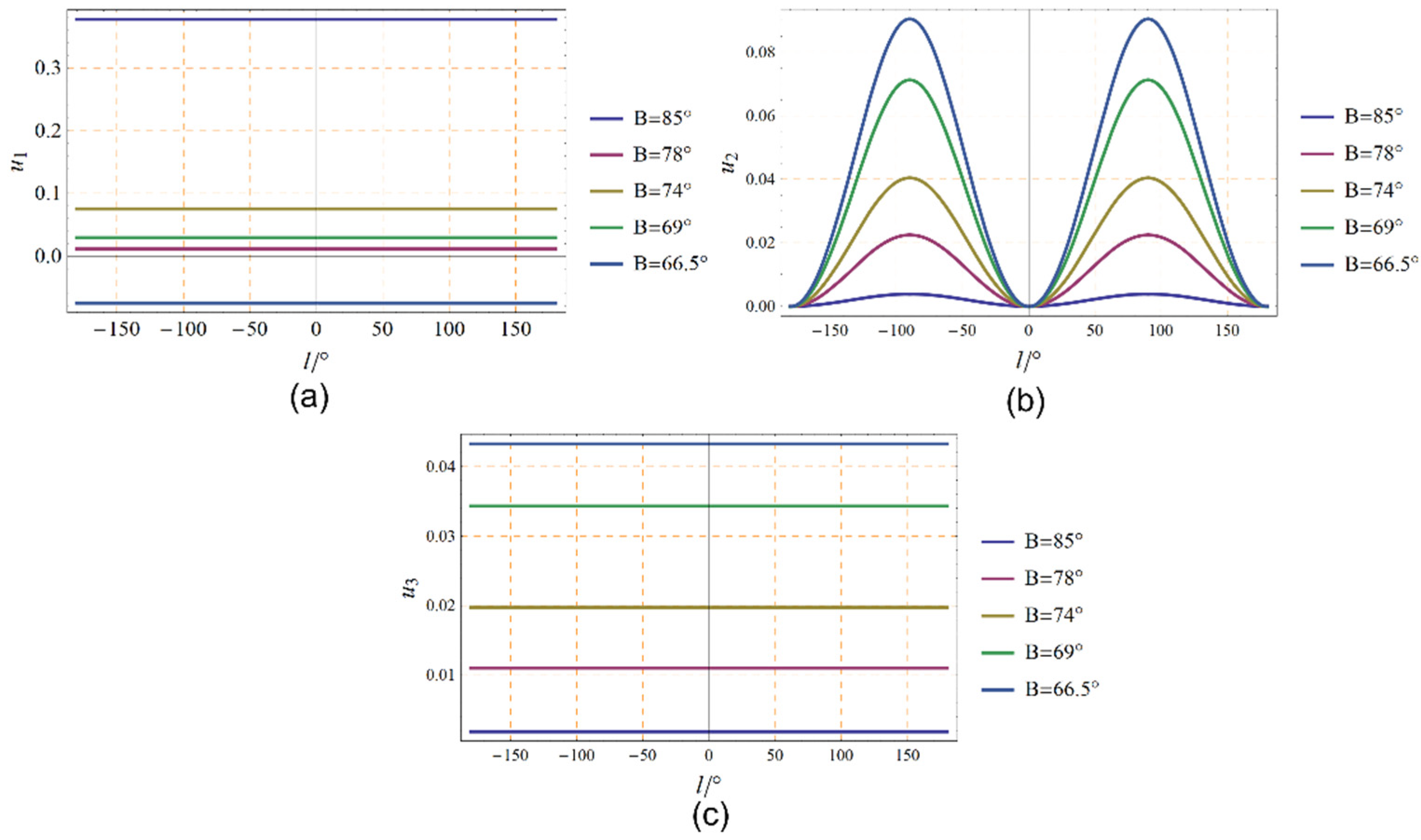
Length distortion is a primary factor in determining which projection is used, and controlling length distortion is crucial in cartography. The variations of u 1 , u 2 , u 3 , with longitude difference l at different circles of latitude, ranging from the Arctic Circle 66.5 to the North Pole 9 0 are shown in Figure 3. To provide a more visual representation of the distortion within the polar regions, the length distortions calculated based on Equations (3), (7), and (10) are listed in Table 1.
The results in Figure 4 and Table 1 show the following:
(1)
In the Mercator projection, there is no length distortion at the reference latitude, while the length distortion is greater than 0 beyond the reference latitude and less than 0 within it. The length distortions are all less than 10% in the region up to 74 , whereas in polar regions with very high latitudes, the maximum distortion can exceed 80%. This suggests that it is possible to control the degree of distortion of the Mercator projection by adjusting the reference latitude, but the Mercator projection is still significantly distorted at high latitudes.
(2)
The length distortions for l = 6 0 are listed in Table 1. In the polar Gauss-Krüger projection, the farther away from the standard meridian, the larger the length distortion is for a fixed longitude difference. At the same latitude, the length distortion increases and then decreases with the longitude difference, reaching a maximum at l = ± 9 0 . The maximum distortion is calculated to be no more than 10%. This shows that the bandwidth can be broadened by using a complex function to represent the Gauss-Krüger projection, which facilitates uniform representation of the land and nautical charts and provides an important reference for scientific research and nautical charting in the polar region.
(3)
The overall distortion of the double polar stereographic projection in the polar region is relatively small, especially above 79 , where the distortion is less than 1%. It has been able to satisfy the compilation of large and medium scale marine charts, which is very important for the application of high-precision polar navigation.

4.2. Distortions of Longitude and Latitude Grid Lines

The establishment of latitude and longitude grids on the plane is the basis for determining the precise position of a ship during polar navigation. The grid of latitude and longitude lines for the Mercator projection is widely known, so it will not be discussed in this paper. Based on the polar Gauss-Krüger projection and polar stereographic projection formulas, the latitude and longitude are plotted as shown in Figure 4. In this case, the meridian starts at 0 longitude, the interval longitude difference is 30 , and the latitude circle starts at 90 latitude. The red solid curves represent the polar stereographic projection; the green dashed curves represent the polar Gauss-Krüger projection; and the gray line shows the boundary line of the Arctic. From Figure 4, it can be observed that the meridians in the polar Gauss projection are radial straight lines centered on the poles, and the latitudinal lines are depicted as concentric circles centered on the poles, whereas the meridians in the polar Gauss-Krüger projection resemble an inverse hyperbola, and the latitudinal lines resemble an ellipse.
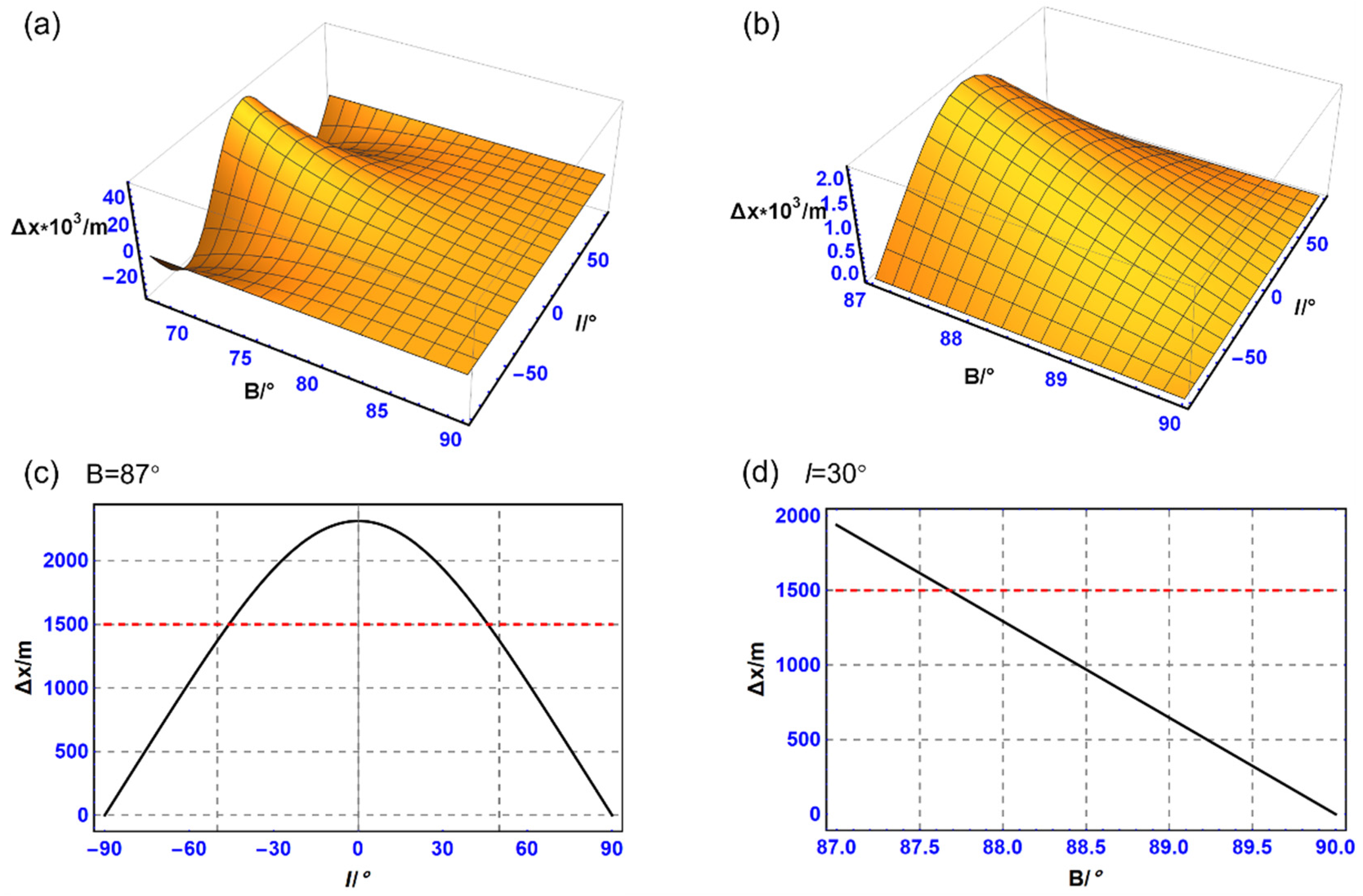
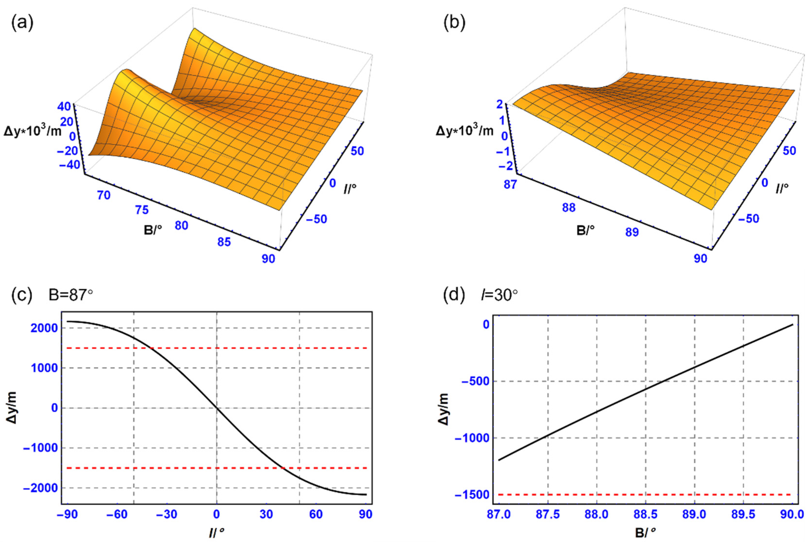
To analyze specifically the differences between the latitude and longitude grids of these two projections at high latitudes, the distribution of the difference Δ x and Δ y between the x and y coordinates in the interval of latitude 87 to 90 and longitude difference 9 0 to 90 are shown in Figure 5 and Figure 6. Figure 5 and Figure 6 show that Δ x decreases with increasing longitude difference and Δ y increases with increasing longitude difference when latitude is fixed. In addition, Δ x and Δ y decrease with increasing latitude when the longitude difference is constant. Normally, in 1:1,500,000 nautical charts, the difference of coordinates on the charts within the region is negligible within 1 mm. Correspondingly, the actual coordinate differences should be less than 1500 m. It is clear that the two projections only have coordinate differences near the poles simultaneously less than 1500 m under the ellipsoid model. Therefore, it is easier to use the dynamic projection to match other auxiliary navigation.
Referring to the existing recommendations for the compilation of ENCs [41,42], the length distortion of berthing and harbor at scales of 1:22,000 and above should be limited to within 5%. The length distortions in the 1:22,000 to 1:90,000 approach are within 10%. The range of distortions in the general scale, ranging from 1:350,000 to 1:1,500,000, is controlled to 40% or less. For overviews at 1:1,500,000 and smaller scales, the range of length distortion can be limited to about 50%. By this convention, the adoption of dynamic projection in the polar region is suggested in this paper. Based on the analysis of the length distortions and the longitude and latitude grid distortions, the projections oriented towards polar navigation are listed in Table 2. It is recommended that the compilation scales for ENCs be based upon standard radar ranges in nautical miles. The smaller the selectable range, the larger the scale of the ENCs, and the more detailed the geographic information displayed on the ECDIS screen. Maritime users can flexibly manage and browse chart information by adjusting selectable distances to suit different navigational needs and scenarios. Here, for the purpose of uniformity of units in the paper, we standardize nautical miles to meters, 1 n mile = 1852 m.

4.3. Accuracy of Direct Transformation between Projections

The aim of this paper is to carry out an accuracy analysis of the direct transformation between the established projections, as follows: Firstly, B 66 . 5 , 9 0 and l 9 0 , 9 0 are substituted into Equations (1), (5), and (8) to get the true value of the projected coordinates. Secondly, the true values of the coordinates are substituted into the projected conversion formulas (Equations (11)~(16)) derived in this paper to get the computed values. Lastly, the computed values are subtracted from the true values to get the computational errors of the conversion formulas. The computational errors of the transformation between the polar Gauss-Krüger projection and the polar stereographic projection are listed in this section, limited by the length of the article. The computational errors of the direct transformation of the polar Gauss-Krüger projection to the polar spherical projection are recorded as Δ x 23 , Δ y 23 , while the computational errors of the direct transformation of the polar spherical projection to the polar Gauss projection are noted as Δ x 32 and Δ y 32 . The variation of the computational errors is shown in Figure 7. As can be seen from Figure 7, the computational errors of the derived direct transformation formulas for both polar Gauss-Krüger projection and polar stereographic projection are less than 1 0 9 m in this paper. The computational errors of the other direct transformation formulas were calculated to be less than 1 0 9 m. The correctness of the derived direct transformation formulas can be proved numerically by taking into account the computational errors inherent in Mathematica.

4.4. Calculation Efficiency Analysis

In order to verify the efficiency of the established direct transformation model among the three projections, B 66 . 5 ,   9 0 , l 0 , 9 0 are selected as the study area, and the transformation between the Gauss-Krüger projection of the polar region and the polar stereographic projection is used as an example. The computational time used for the three resolutions of 1 × 1 , 1 × 1 , 0 . 1 × 0.1 is measured and is shown in Table 3. The resolution of 1 × 1 requires the computation of 2 115 points; the resolution of 1 × 1 includes 7.614 million points; and the resolution of 0 . 1 × 0.1 requires the calculation of 761.4 million points. Here, the 0 . 1 × 0.1 resolution is chosen because of the format of XX°XX.XXXX′ in which nautical users enter the coordinates of points on ECDIS. In the table, t 1 is defined as the computational time used for the direct conversion of the polar Gauss-Krüger projection to polar stereographic projection, and t 2 represents the computational time used for the direct conversion of polar stereographic projection to polar Gauss-Krüger projection. The algorithm is tested in the following environment:
Hardware environment: the processor is AMD Ryzen 7 5800H with Radeon Graphics 3.20 GHz, RAM is 16.0 GB; the graphics card is AMD Radeon (TM) Graphics.
Software environment: Windows 11, 64-bit, MATLAB R2019av9.6.0.
According to Table 3, the time taken for the direct transformation between the polar Gauss-Krüger projection and the polar stereographic projection also does not exceed 0.1s for the calculation of nearly 8 million points at 1 × 1 resolution, which can better satisfy the higher requirements of high-precision ENCs in terms of resolution and projection transformation efficiency.

5. Visualization of Dynamic Chart Projection

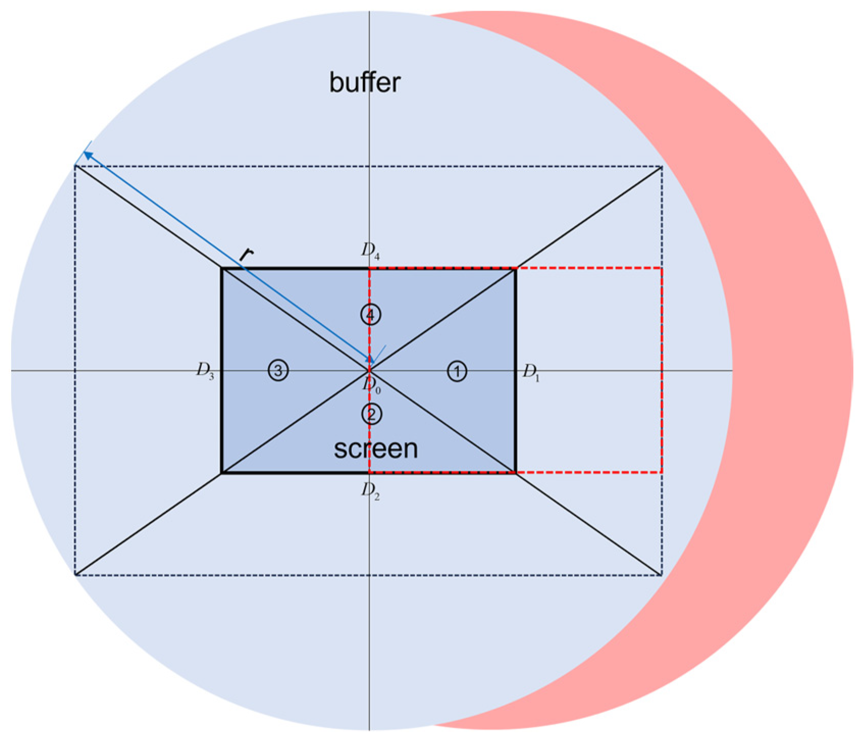
The real-time capability of the dynamic projection can meet the needs of route changing at any time when the ship navigation path is determined. In this paper, a method based on buffer analysis is proposed. The projection area is determined according to the real-time position of the object, and adaptive visualization is achieved using a multithread-double buffer dynamic scheduling algorithm. The specific process of dynamic chart projection implementation is shown in Figure 8. The radius r of the buffer is determined by the relationship between the screen size and the current map scale. The radius r of the buffer is determined by the relationship between the screen size and the current map scale. Screen width and height are represented by w and h, respectively, and scale is the current scale.
r = w 2 + h 2 s c a l e
The current point of the ship’s navigation, which is placed at the center of the screen, is set as the initial point for the projection. A circular buffer is formed with the center of the projected datum and a radius of r , and all objects within the buffer are projected. The next projection reference point is judged by the real-time position of the ship’s movement. Specifically, this is achieved by dividing the screen into four parts, as shown in Figure 9, and if the point is located in area i, then D i is used as the next projection reference point. For fast transitions in navigation scenarios, a double buffering technique can be used. The double buffer technique means that two buffers (the front buffer and the back buffer) are used to store and display images alternately. In general, the front buffer is used to display the current image, and the back buffer is used to render the new image. While the vessel is moving, the back buffer is exchanged with the chart information displayed on the screen of the ECDIS, so that the ENCs are ensured to display updates smoothly and quickly. Dynamic chart projection is required to visualize, while completing the projection transformation based on the next projection datum, which can be made more efficient using multithreaded techniques. The main thread is dedicated to loading the chart data centered on the current projection reference point. It also focuses on providing the navigation-related details that the user is interested in during the navigation process. The sub-thread is applied to load the chart data for the next projection datum. Because the projection area corresponding to the current projection datum covers a larger area than the current screen, fast visualization of the projection area can be achieved by the technique of double buffering.

6. Conclusions

In order to solve the problem that the projection used in ENCs is not fully applicable to polar navigation, an ENC projection suitable for polar navigation, based on the theory of complex function, is analyzed in detail. Direct transformations of Mercator projection, polar Gauss-Krüger projection, and polar stereographic projection are derived, dynamic projections oriented to polar navigation are designed, and an ENCs visualization idea based on multithread-double buffering is developed. Taking the CGCS2000 reference ellipsoid as an example for calculation, the Mercator projection has less than 10% distortion up to 74° latitude, but distortion exceeds 80% at extreme high latitudes. The maximum distortion of the polar Gauss-Krüger projection does not exceed 10%. Polar stereographic projection is shown to be less than 1% above 79°. From the perspective of longitude and latitude grid lines, the polar Gauss-Krüger projection and the polar stereographic projection differ only to a small extent near the poles. By combining the existing specifications for the compilation and mapping of ENCs, recommendations for the projections oriented towards polar navigation at different scales and in different latitude bands for different applications are given. Taking the transformation between the Gauss-Krüger projection and the polar stereographic projection in the polar region as an example, the computational error of the direct transformation formula is less than 1 0 9 m, and the time does not exceed 0.1 s for the calculation of nearly 8 million points at 1 × 1 resolution, which fully meets the demand of high-precision ENCs for resolution and projection transformation efficiency.
In conclusion, the adverse effects on navigation caused by projection errors in ENCs can be effectively eliminated by the established dynamic projection and visualization methods for polar navigation. By providing high-precision spatial and temporal information services and improving the visualization of navigation software for smart ships, it can better serve polar scientific research, ocean shipping, and other related fields, while also reducing navigation risks.

Author Contributions

Conceptualization, C.J. and X.W.; formal analysis, C.J. and S.B.; funding acquisition, X.W.; investigation, C.J. and H.L.; methodology, C.J., X.W., H.L. and S.B.; resources, C.J. and X.W.; software, C.J. and H.L.; supervision, S.B.; validation, H.L.; visualization, C.J. and S.B.; writing—original draft, C.J.; writing—review and editing, S.B. and X.W. All authors have read and agreed to the published version of the manuscript.

Funding

This work was supported by The National Science Foundation for Outstanding Young Scholars of China (42122025); The National Natural Science Foundation of China (42074010).

Institutional Review Board Statement

Not applicable.

Informed Consent Statement

Informed consent was obtained from all subjects involved in the study.

Data Availability Statement

Data are contained within the article.

Acknowledgments

The earth parameters are from CGCS2000 and the arctic boundary data in this paper come from the National Oceanic and Atmospheric Administration (NOAA), which are public data. Geocartv3.2.0, MATLAB, and Mathematica were used for image presentation and data analysis. We express our sincere gratitude to these organizations and software providers.

Conflicts of Interest

The authors declare no conflicts of interest.

References

  1. Yastrebova, A.; Höyhtyä, M.; Boumard, S. Positioning in the Arctic Region: State-of-the-Art and Future Perspectives. IEEE Access 2021, 9, 53964–53978. [Google Scholar] [CrossRef]
  2. Li, X.; Otsuka, N.; Brigham, L. Spatial and temporal variations of recent shipping along the Northern Sea Route. Polar Sci. 2021, 27, 100569. [Google Scholar] [CrossRef]
  3. Screen, J.; Simmonds, I. The central role of diminishing sea ice in recent Arctic temperature amplification. Nature 2010, 464, 1334–1337. [Google Scholar] [CrossRef] [PubMed]
  4. Beveridge, L.; Fournier, M.; Lasserre, F.; Huang, L. Interest of Asian Shipping Companies in Navigating the Arctic. Polar Sci. 2016, 10, 404–414. [Google Scholar] [CrossRef]
  5. Liang, S.; Zeng, J.; Li, Z. Spatio-temporal analysis of the melt onset dates over Arctic sea ice from 1979 to 2017. Acta Oceanol. Sin. 2022, 41, 146–156. [Google Scholar] [CrossRef]
  6. Cheng, J.; Liu, J.; Zhao, L. Survey on polar marine navigation and positioning system. Chin. J. Ship Res. 2021, 16, 16–29. [Google Scholar]
  7. Plass, S.; Clazzer, F.; Bekkadal, F. Current situation and future innovations in Arctic communications. In Proceedings of the Vehicular Technology Conference, Boston, MA, USA, 6–9 September 2015; pp. 1–7. [Google Scholar]
  8. Liu, Z.; Zhang, B.; Zhang, M. A quantitative method for the analysis of ship collision risk using AIS data. Ocean Eng. 2023, 272, 113906. [Google Scholar] [CrossRef]
  9. Chen, X.; Liu, S.; Liu, R.W. Quantifying Arctic oil spilling event risk by integrating an analytic network process and a fuzzy comprehensive evaluation model. Ocean Coast. Manag. 2022, 228, 106326. [Google Scholar] [CrossRef]
  10. Yao, Y.; Xu, X.; Li, Y. Transverse Navigation under the Ellipsoidal Earth Model and its Performance in both Polar and Non-polar areas. J. Nav. 2016, 1, 1–18. [Google Scholar] [CrossRef]
  11. Naumann, J. Grid navigation with polar stereographic charts. Eur. J. Navig. 2011, 9, 4–8. [Google Scholar]
  12. Lapon, L.; Ooms, K.; Maeyer, P. The Influence of Map Projections on People’s Global-Scale Cognitive Map: A Worldwide Study. Int. J. Geo Inf. 2020, 9, 196. [Google Scholar] [CrossRef]
  13. Baselga, S. Two Conformal Projections for Constant-Height Surface to Plane Mapping. J. Surv. Eng. 2021, 147, 06020004. [Google Scholar] [CrossRef]
  14. Beresford, P. Map Projection Used in Polar Regions. J. Nav. 1953, 6, 29–37. [Google Scholar] [CrossRef]
  15. Snyder, J. Map Projections-A Working Manual; United States Government Printing Office: Washington, DC, USA, 1987.
  16. Grafarend, E.; You, R.; Syffus, R. Map Projections; Springer: Berlin/Heidelberg, Germany, 2014. [Google Scholar]
  17. Pearson, F. Map Projections: Theory and Applications; CRC Press: Boca Raton, FL, USA, 1990. [Google Scholar]
  18. Smith, L.; Stephenson, S. New Trans-Arctic shipping routes navigable by midcentury. Proc. Natl. Acad. Sci. USA 2013, 110, E1191–E1195. [Google Scholar] [CrossRef] [PubMed]
  19. Pallikaris, A.; Tsoulos, L. Map projections and visualization of navigational paths in electronic chart systems. In Proceedings of the 3rd International Conference on Cartography and GIS, Nessebar, Bulgaria, 15–20 June 2010; pp. 15–20. [Google Scholar]
  20. Skopeliti, A.; Tsoulos, L. Choosing a Suitable Projection for Navigation in the Arctic. Mar. Geod. 2013, 36, 234–259. [Google Scholar] [CrossRef]
  21. Peter, O. The Mercator Projections; Edinburgh University Press: Edinburgh, UK, 2008; pp. 23–29. [Google Scholar]
  22. Pallikaris, A. Choosing Suitable Map Projections for World-wide Depiction of Electronic Charts in ECDIS. Coordinates 2014, 10, 21–28. [Google Scholar]
  23. Xiong, J. Ellipsoid Geodesy; Chinese People’s Liberation Army Publishing House: Beijing, China, 1988. [Google Scholar]
  24. Wang, H.; Zhang, W.; Zhang, P. Polar Navigation Method Based on Polar Stereographic Projection. Command Control Simul. 2016, 38, 106–109. [Google Scholar]
  25. Wen, C.; Bian, H.; Gao, X. Availability Analysis of Mercator Projection in Nautical Charts’ Compilation in Polar Regions. Appl. Mech. Mater. 2014, 535, 556–561. [Google Scholar] [CrossRef]
  26. Bowring, B. The Transverse Mercator Projection—A Solution by Complex Numbers. Surv. Rev. 1978, 30, 325–342. [Google Scholar] [CrossRef]
  27. Bian, S.; Li, Z.; Li, H. The Non-singular Formula of Gauss Projection in Polar Regions by Complex Numbers. Acta Geod. Cartogr. Sin. 2014, 43, 348–352+359. [Google Scholar]
  28. Li, Z.; Bian, S.; Jin, L. Forward and Inverse Expressions of Polar Gauss Projection without Zoning Limitations. Acta Geod. Cartogr. Sin. 2017, 46, 780–788. [Google Scholar]
  29. Guo, J.; Shen, W.; Ning, J. Development of Lee’s exact method for Gauss-Krüger projection. J. Geod. 2020, 94, 58. [Google Scholar] [CrossRef]
  30. Wen, C.; Bian, H. Polar grid rumble route based on polar stereographic projection. Acta Geod. Cartogr. Sin. 2019, 48, 18–23. [Google Scholar]
  31. Jenny, B. Adaptive composite map projections. IEEE Trans. Vis. Comput. Graph. 2012, 18, 2575–2582. [Google Scholar] [CrossRef]
  32. Jenny, B.; Šavrič, B.; Patterson, T. A compromise aspect-adaptive cylindrical projection for world maps. Int. J. Geogr. Inf. Sci. 2015, 29, 935–952. [Google Scholar] [CrossRef]
  33. Palikaris, A.; Mavraeidopoulos, A. Electronic navigational charts: International standards and map projections. J. Mar. Sci. Eng. 2020, 8, 248. [Google Scholar] [CrossRef]
  34. Gosling, P.; Symeonakis, E. Automated map projection selection for GIS. Cartogr. Geogr. Inf. Sci. 2020, 47, 261–276. [Google Scholar] [CrossRef]
  35. Jiao, C. Computer Algebraic Analysis and Optimization of Common Map Projection Deformation. Master’s Thesis, China University of Geosciences (Wuhan), Wuhan, China, 2022. [Google Scholar]
  36. Li, X.; Li, H.; Liu, G.; Bian, S. Optimization of Complex Function Expansions for Gauss-Krüger Projections. ISPRS Int. J. Geo Inf. 2022, 11, 566. [Google Scholar] [CrossRef]
  37. Li, X.; Li, H.; Liu, G.; Bian, S.; Jiao, C. Simplified Expansions of Common Latitudes with Geodetic Latitude and Geocentric Latitude as Variables. Appl. Sci. 2022, 12, 7818. [Google Scholar] [CrossRef]
  38. Karney, C.F.F. On auxiliary latitudes. Surv. Rev. 2023, 56, 165–180. [Google Scholar] [CrossRef]
  39. Bermejo, M.; Otero, J. Simple and highly accurate formulas for the computation of Transverse Mercator coordinates from longitude and isometric latitude. J. Geod. 2009, 83, 1–12. [Google Scholar] [CrossRef]
  40. Wang, K.; Ye, S.; Gao, P.; Yao, X.; Zhao, Z. Optimization of Numerical Methods for Transforming UTM Plane Coordinates to Lambert Plane Coordinates. Remote Sens. 2022, 14, 2056. [Google Scholar] [CrossRef]
  41. GB 12320-2022; Compilation Specifications for Chinese Nautical Charts. Standards Press of China: Beijing, China, 2022.
  42. International Hydrographic Organization. Electronic Navigational Charts (ENC)–Production, Maintenance and Distribution Guidance; Edition 2.1.0; Publication S-65; IHO: Monaco, France, 2017.
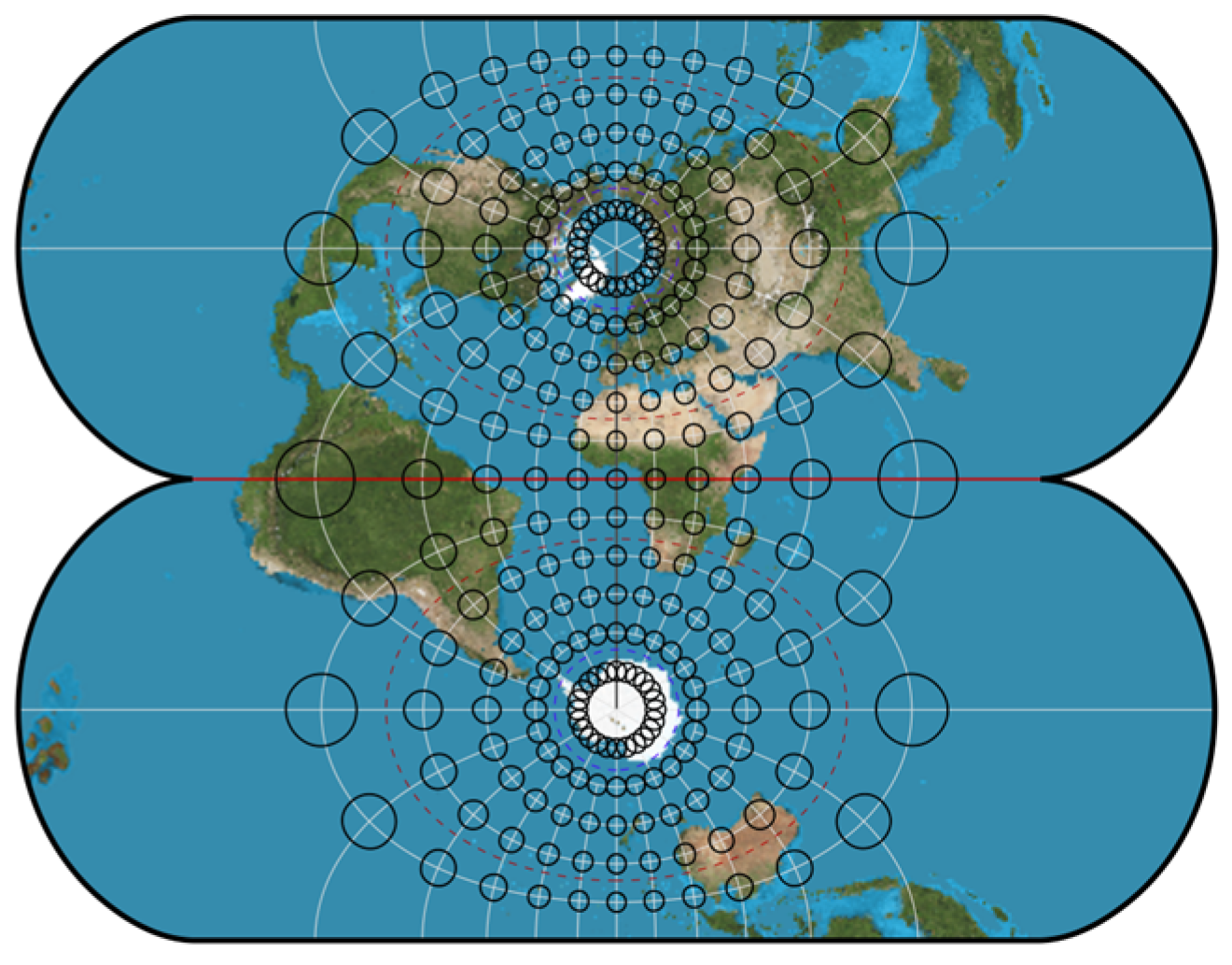
Figure 1. Sketch of Gauss-Krüger projection.
Jmse 12 00577 g001
Figure 2. Sketch of polar stereographic projection.
Jmse 12 00577 g002
Figure 3. Variation of length distortion with longitude difference l ((a) Mercator projection; (b) polar Gauss-Krüger projection; (c) polar stereographic projection).
Jmse 12 00577 g003
Figure 4. Comparison of the two projections. (a) Schematic of the latitude lines at the Arctic; (b) schematic of the meridians at the Arctic, where the red solid curves represent the polar stereographic projection; the green dashed curves represent the polar Gauss-Krüger projection; and the gray line shows the boundary line of the Arctic.
Jmse 12 00577 g004
Figure 5. Distribution of Δ x . (a) Distribution of Δ x in the latitude range of 66.5 ~ 90 , longitude difference 90 ~ 90 ; (b) distribution of Δ x in the latitude range of 87 ~ 90 , longitude difference 90 ~ 90 ; (c) distribution of Δ x as a function of longitude difference l for B = 87 ; (d) distribution of Δ x with latitude B at l = 30 . The black solid line shows the curve of Δ x as a function of l and B . The red dotted line indicates the maximum allowable distance (1500 meters) for Δ x in a 1:1.5 million chart.
Jmse 12 00577 g005
Figure 6. Distribution of Δ y (a) Distribution of Δ y in the range of latitude 66.5 ~ 90 , longitude difference 90 ~ 90 ; (b) distribution of Δ y in the latitude range of 87 ~ 90 , longitude difference 90 ~ 90 ; (c) distribution of Δ y as a function of longitude difference l for B = 87 ; (d) distribution of Δ y with latitude B at l = 30 . The black solid line shows the curve of Δ y as a function of l and B . The red dotted line indicates the maximum allowable distance (1500 meters) for Δ y in a 1:1.5 million chart.
Jmse 12 00577 g006
Figure 7. Calculation error of the transformation between polar Gauss-Krüger projection and polar stereographic projection. (a) Calculation error of Δ x 23 ; (b) calculation error of Δ y 23 ; (c) calculation error of Δ x 23 ; (d) calculation error of Δ y 23 , where the direct transformation of the polar Gauss-Krüger projection to the polar spherical projection are recorded as Δ x 23 , Δ y 23 , and the computational errors of the direct transformation of the polar spherical projection to the polar Gauss projection are noted as Δ x 23 , Δ y 23 .
Jmse 12 00577 g007
Figure 8. Schematic diagram of the realization process of dynamic chart projection.
Jmse 12 00577 g008
Figure 9. Selection of the projection reference point and the corresponding projection (the dark blue portion of the figure in the thick black rectangular box is the front buffer, which displays the chart information from the ECDIS screen. The light blue portion and the red portion are the back buffers. Assuming that the next position of the ship is located in zone 1, the next projection datum is D 1 . The red part is the buffer with D 1 as the projection datum buffer).
Jmse 12 00577 g009
Table 1. Length distortions at significant nodes within 66.5° to 90° of three projections.
BType of Projection
Mercator ProjectionPolar Gauss-Krüger Projection
(l = 60°)
Polar Stereographic Projection
66.5−0.0747870.0655170.043240
690.0293600.0519230.034335
700.0785200.0469640.031079
71−0.0894660.0422720.027993
740.0753660.0297620.019747
750.1452090.0261020.017328
76−0.1306580.0226930.015073
780.0114970.0166130.011045
790.1021350.0139380.009270
800.2110280.0115020.007653
81−0.2326510.0093040.006193
83−0.0150440.0056160.003741
850.3772250.0028610.001906
86−0.8382130.0018300.001219
88−0.6766270.0004570.000305
9000
Table 2. Projections facing polar navigation at different scales.
NameScale RangeSelectable Range
(m)
DeformationRange of LatitudesProjection
Berthing>1:4000463<5% 66.5 ~ 69 Mercator Projection
69 ~ 79 Polar Gauss-Krüger Projection
79 ~ 90 Polar Stereographic Projection
Harbor1:4000~1:22,0002778<5% 66.5 ~ 69 Mercator Projection
69 ~ 79 Polar Gauss-Krüger Projection
79 ~ 90 Polar Stereographic Projection
Approach1:1:22,000~1:90,00011,112<10% 66.5 ~ 74 Mercator Projection
74 ~ 79 Polar Gauss-Krüger Projection
79 ~ 90 Polar Stereographic Projection
Coastal1:90,000~1:350,00044,448<30% 66.5 ~ 83 Mercator Projection
83 ° ~ 90 Polar Stereographic Projection
General1:350,000~1:1,500,000177,792<40% 66.5 ~ 85 Mercator Projection
85 ~ 90 Polar Stereographic Projection
Overview<1:1,500,000407,440<50% 66.5 ~ 85 Mercator Projection
85 ~ 90 Polar Stereographic Projection
Table 3. Calculational time (unit: s).
FormTime (s)Resolution
1 × 1 1 × 1 0.1 × 0.1
x 2 , y 2 x 3 , y 3 t 1 0.00183890.081655197.8277
x 3 , y 3 x 2 , y 2 t 2 0.00199540.067192203.3265
Disclaimer/Publisher’s Note: The statements, opinions and data contained in all publications are solely those of the individual author(s) and contributor(s) and not of MDPI and/or the editor(s). MDPI and/or the editor(s) disclaim responsibility for any injury to people or property resulting from any ideas, methods, instructions or products referred to in the content.