Article

An Anti-Windup Method Based on an LADRC for Miniaturized Inertial Stabilized Platforms on Unmanned Vehicles in Marine Applications

1
College of Intelligent Systems Science and Engineering, Harbin Engineering University, Harbin 150001, China
2
The 54th Research Institute of China Electronics Technology Group Corporation, Shijiazhuang 050081, China
*
Author to whom correspondence should be addressed.
J. Mar. Sci. Eng. 2024, 12(4), 616; https://doi.org/10.3390/jmse12040616
Submission received: 9 March 2024 / Revised: 27 March 2024 / Accepted: 1 April 2024 / Published: 2 April 2024

Abstract

:
This paper investigates an anticipatory activation anti-windup approach based on Linear Active Disturbance Rejection Control (LADRC) to address the influences of accelerated saturation on the actuators in a Miniaturized Inertial Stabilized Platform (MISP) with extreme external disturbance. The proposed method aims to eliminate the high-frequency vibrations on the Line of Sight (LOS) of electro-optical devices during actuator saturation. To achieve this, the Linear Extended State Observer (LESO) is modified by adding saturation feedback to the total disturbance observed state variable, which is operated as an anticipatory activation anti-windup compensator. The stability of the proposed controller is discussed, and the gains are optimized by the Linear Matrix Inequality (LMI) constraints though quadratic programming and an H-infinite performance indicator. Additionally, as the multiple activated scheme for anti-windup, the effectiveness of immediate activation in dealing with accelerated saturation is compared and analyzed. These comparisons and verification are implemented through simulations, where the external disturbance is introduced using recorded attitude data from USV sailing. Finally, experiments are conducted on an MISP for a visual tracking system, demonstrating that the anticipatory activation mothed effectively suppresses high-frequency vibrations on the LOS during instances of accelerated saturation.

1. Introduction

The Miniaturized Inertial Stabilized Platform (MISP) presents extensive application in Unmanned Aerial Vehicles (UAVs) and Unmanned Surface Vehicles (USVs) to stabilize electro-optical devices for high-precision control of the Line of Sight (LOS) [1,2,3,4,5]. This technology is indispensable for performing complex tasks, such as visual-aided autonomous navigation [6,7,8,9,10] and target tracking in coast patrol [11,12]. Moreover, the joint USV-UAV operations [13,14,15,16] in marine environments characterized by complex and random disturbances, such as wave motion, turbulence, and environmental gusts, are also required urgently. To meet the requirements of unmanned vehicle applications, researchers have been dedicated to enhancing the performance of the MISP. The modified Kalman filter has been applied in dual-axial MISPs to enhance precision in target tracking for surveying and mapping [17]. Furthermore, the angular signal of an MISP is leveraged to improve navigation precision for obstacle detection and avoidance [18,19]. Refs. [20,21] employed a camera-stabilized gimbal system to track the landmarks for localization and navigation when an autonomous vehicle explores the unknown and GPS signals are denied in the environments. Ref. [22] implemented a dynamic camera for visual-inertial navigation using an MISP, with the parametrization of the actuated mechanism enabling online calibration.
Currently, to meet the requirements of diverse loads for the miniaturized unmanned vehicles, gear-driven actuators with a large torque output are employed in MISPs to adjust the frame for stabilizing the LOS. However, the actuators experience saturation in angular acceleration during the stabilized control of the LOS when unmanned vehicles operate with high-frequency and large-amplitude external disturbances, such as marine environments. The vibrations caused by accelerated saturation affect the target identification for the visual sensors, particularly when the MISP operates in a low-power condition of the unmanned vehicle. Therefore, the problems in the control system are characterized by high-frequency random disturbances and uncertain conditions; most control strategies are restricted by the demand for the low-cost of the design of the MISP.
Fortunately, the Active Disturbance Rejection Controller (ADRC), proposed in the 1990s by Han and theorized in [23], does not rely on the system model and exhibits a superior performance in addressing uncertain conditions during the control process. Particularly, Gao designed the Linear ADRC (LADRC) by applying the scaling and bandwidth parameterization mentioned in [24], to meet the demands of convenient application, especially when operated on low-cost microchips for designers. In recent years, researchers have utilized a modified ADRC to enhance system performance under nonlinear constraints and actuator saturation. Ref. [25] combines the trajectory linearization control and ADRC for a hypersonic reentry vehicle attitude tracking system, achieving a good performance when overcoming actuator saturation. Refs. [26,27] investigate the use of an ADRC for stabilizing nonlinear systems with actuator saturation and demonstrate that local stabilization can be achieved in a region including the origin. Moreover, modified Extended State Observer (ESO) techniques have been proposed in [28,29,30,31] to estimate system states and disturbances simultaneously without a time delay. These techniques are adapted as anti-windup compensators to address input saturation and time delays in actuators. A novel robustness controller for the anti-windup loop has been modified using an improved ESO, which accurately estimates the state and disturbance under Magnitude and Rate Saturation (MRS) conditions, thereby enhancing the stability of uncertain nonlinear systems [32]. The anti-windup ESO is proposed to estimate disturbances under input saturations, demonstrating good performances in both Unmanned Ground Vehicles (UGVs) path-following control [33] and turbofan engine systems [34]. Refs. [35,36,37,38] investigate a multiple activated scheme for anti-windup control, which is convenient to be realized in engineering, especially satisfying the low-cost controller for the antenna servo system in uncertain conditions when combined with an LADRC. A robust, adaptive, multistage anti-windup control based on anticipatory activation is developed in [39] to handle input constraint for dynamic-positioning ships and improves the transient performance significantly. Ref. [40] investigates a permanent-type axial-gap-bearing motorless control system, which includes a robust controller combined with disturbance observers and anticipatory activation anti-windup compensator, achieving high-accuracy control for speed tracking. However, the methods mentioned above do not consider situations where the actuator is limited by acceleration. As an unmanned miniaturized device, the performance of the actuator’s acceleration is constrained by power supplies and often overlooked by designers. Therefore, an anti-windup LADRC with an anticipatory activation compensator is proposed to address these challenges. The primary contributions of this research could be summarized as follows:
  • Accelerated saturation in gear actuators is proposed for the first time. The model of this phenomenon is developed, and its influence on MISPs is analyzed. To address this problem, an anti-windup method based on an LADRC is proposed. This method can be conveniently implemented in a low-cost system;
  • As part of the multiple activated anti-windup method, the limitations of immediate activations in dealing with accelerated saturation are analyzed. By combining the LESO with saturation feedback, the modified anticipatory activation anti-windup compensator is proposed and verified;
  • The proposed method enhances the robustness of visual tracking by the MISP control system, effectively mitigating the high-frequency vibrations on the LOS induced by accelerated saturation, thereby improving the effectiveness of target identification.
The rest of this paper is organized as follows. In Section 2, the accelerated saturation is modeled and analyzed. In Section 3, the proposed controller is designed and discussed in detail. In Section 4, simulations of the proposed method are implemented based on angular rate tracking for stabilized control. In Section 5, experiments are conducted with a visual stabilized and tracking platform. Finally, the conclusions are presented in Section 6.

2. Model of Accelerated Saturation

The actuator’s acceleration constraint could be represented as an input saturation model, which facilitates the analysis and is addressed by an anti-windup method. This model is expressed as:
sat(u) = sign(u)min{|ka·u|, amax}
As illustrated in Figure 1, the saturation function, denoted as sat(u), comprises a linear segment with a gain, ka, and the output is a = ka·u, representinng the acceleration of the actuator. Then, a saturation segment with a limitation of amax, corresponding to the input, ua, represents the maximum absolute value of acceleration.
The stabilized control system for the MISP, as illustrated in Figure 2, incorporates the accelerated saturation of the actuator. It operates as an inertial stabilized loop when the input reference, r = 0, serves as an inertial tracking loop when r represents the command from the tracking sensors. The input of the controller, C(s), is the error between r and the feedback in the angular rate from the Inertial Measurement Unit (IMU) provided by the transfer function, H(s). The output, u = E(s)C(s), represents the control signal in acceleration and is limited by the saturation function, sat(u), then integrated as the input angular rate order of the actuator. Furthermore, the external disturbance, d, introduced by the motions of the UAV or USV can be compensated for by the stabilized control loop for the LOS.
The model of the actuator can be described by Equation (2), where the gain, km, represents the relation of the actuator between the input order and rotary output. The gain, km, is determined by the gear reducer ratio and the motor’s precision in control. Both the output of the actuator in angle θm and angular rate ωm are related to the input order, rm, and its differential value. The output of the controller, u, is constrained by the saturation function, sat(u), which limits the input of the actuator in acceleration denoted as r ¨ m .
θ m = k m r m ω m = k m r ˙ m r ¨ m = s a t ( u )

3. Tracking System with the Anti-Windup LADRC

3.1. Optimal Desgin for the Anti-Windup LADRC

In the visual tracking control system with actuator saturation, the inertial stabilized platform is considered as a 2-axis-frame control system. Each frame is controlled individually and treated as a Single Input Single Output (SISO) model with second order. Combining the model (2), the single frame control system can be described by Equation (3), where the variable x1 denotes the angle of the LOS and the variable x2 denotes the angular rate of the LOS. Additionally, the disturbance of the system is considered and denoted as f (x1, x2, ω(t), t).
x ˙ 1 = x 2 x ˙ 2 = f ( x 1 , x 2 , ω ( t ) , t ) + b s a t ( u ) y = x 1
ω(t) represents the external disturbance angular rate, and the disturbance f (x1, x2, ω(t), t) includes the mechanical deviations and internal influences that cannot be measured. According to the method of LESO as depicted in Equation (4), the uncertain conditions leading to vibrations in the LOS mentioned above can be extended as the state variable x3 and observed as the total disturbance. The gain b = Δb + b0, where Δb is an uncertain factor in the system parameters and is included in x3. The state variable, x3, also includes the disturbance from saturation.
x ˙ 1 = x 2 x ˙ 2 = x 3 + b 0 u x ˙ 3 = h ( x 1 , x 2 , ω s a t ( t ) , t ) y = x 1
To analyze the system using the robustness H-infinity model, let the state vector be represented as x p = [ x 1 , x 2 , x 3 ] T , ω = [ v 1 , v 2 , h ] T . The system is expressed in Equation (5).
x ˙ p = A p x p + B 1 ω + B 2 u z p = C 1 x p + D 11 ω + D 12 u y = C 2 x p
The performance output, denoted as zp, is designed for a quadratic programming model. Then, the weighted value matrix is designed as shown in Equation (6).
A P = 0 1 0 0 0 1 0 0 0 , B 1 = 0 0 0 0 0 0 0 0 1 , B 2 = 0 b 0 0 , C 1 = q 1 0 0 0 q 2 0 0 0 q 3 0 0 0 , C 2 = 1 0 0 , D 12 = 0 0 0 ρ
Then, the closed-loop system is optimized for the H-infinity tracking performance, leading to the expression D 11 = 0 , and defining the constraint condition in Equation (7).
0 ( q 1 x 1 2 + q 2 x 2 2 + q 3 x 3 2 + ρ u 2 ) d t < 0 ω 2 d t
As stated in Equation (8), the H-infinity norm of the closed-loop transfer function from the disturbance, w, to the performance output, zp, is constrained to be less than γ.
T ω z ( s ) = sup ω 0 z p 2 ω 2 < γ
The system is designed to track the input reference while compensating for the total disturbance, including the external disturbance and the effects of accelerated saturations as defined in the vector ω. Additionally, the controller aims to optimize the tracking performance whilst complying with the constraints mentioned during disturbances.

3.2. Tracking Controller with a Modified LESO

As illustrated in Figure 3, we created a visual tracking control system in a single frame for the MISP based on an LADRC with an anti-windup compensator.
The proposed scheme comprises a visual tracking part consisting of a Tracking Differentiator (TD) and Proportional plus Derivative (PD) controller. Then, the stabilized part is implemented by the total disturbance observed variable, denoted as − z3/b0. As the visual tracking input, v0 represents the bias of the identified target to the center of the Field of View (FOV); hence, vs = 0. The accelerated saturation of the actuator can introduce nonlinear uncertainties leading to vibrations on the LOS.
To address this issue, an anti-windup method with the modified LESO is proposed, as show in Equation (9).
z ˙ 1 = z 2 l 1 ε z ˙ 2 = z 3 l 2 ε + b 0 u z ˙ 3 = l 3 ε j a q
where q = usat(u), which represents the feedback of the accelerated saturation for the LESO. The vector L = [ l 1 , l 2 , l 3 ] is defined as the the observer gains to be designed, and the observed errors are defined by the vector e r = [ e r 1 , e r 2 , e r 3 ] T , e r i = z i x i , i = 1 , 2 , 3 . Then, the observed errors, er, can be expressed as:
e ˙ r = ( A p L C 2 ) e r + D h ω + D q q
The matrixes are set as follows:
A p L C 2 = l 1 1 0 l 2 0 1 l 3 0 0 , D h = 0 0 0 0 0 0 0 0 1 D q = 0 0 j a
The total disturbance, f, and the saturation factor, q, are differentiable with respect to t; it was determined that the observed errors, er, are bounded f and q values by designing the system in reality. As can be observed in [24], if the matrix ( A p L C 2 ) is Hurwitz, the gain, L, is converted by the positive parameter ωe > 0, which represents the frequency bandwidth of the LESO, as shown in Equation (11).
s I ( A p L C 2 ) = ( s + ω e ) 3 = 0
where
l 1 = 3 ω e , l 2 = ω e 2 , l 3 = ω e 3
This can be designed by placing all poles at −ωe, and additionally confirmed by the condition that the LESO is BIBO stable. When the state variables are observed by the LESO with er → 0, the control signal of the actuator, u, is illustrated in Equation (13). It consists of the output of the tracking part represented by u0 with gains of k1 and k2 and the stabilized part including the compensation for the accelerated saturation in z3 with the gain b0.
u = u 0 z 3 / b 0 = k 1 ( v 1 z 1 ) + k 2 ( v 2 z 2 ) z 3 / b 0

3.3. Gains of the System for Robustness in Stability

The saturation feedback, q, can be traded as an adaptation parameter with a gain of ja. Then, the gains of the controller can be defined as K, which is a matrix with the gains to be adjusted and denoted as u = Kxk. The observed vector of the LESO is denoted as x k = [ z 1 , z 2 , z 3 ] T . Then, the cotroller base on the state variable feedback is designed as Equation (14).
x ˙ k = ( A p + B 2 K ) x k + B 1 ω z p = ( C 1 + D 12 K ) x k
Then, the constraint condition in the H-infinite norm is represented as (15):
T ω z ( s ) = ( C 1 + D 12 K ) [ s I ( A p + B 2 K ) ] 1 B 1 < γ
The closed-loop system mentioned above is asymptotically stable, and the condition for the H-infinite norm of the transfer function from w to zp being less than γ is the existence of a positive definite matrix, P 1 = P 1 T > 0 , and P2 satisfying the following conditions:
A p P 1 + P 1 A p + B 2 P 2 + P 2 B 2 T + γ 2 B 1 B 1 T ( C 1 P 1 + D 12 P 2 ) T C 1 P 1 + D 12 P 2 I < 0
The state feedback robust controller is u = P 2 P 1 1 x k . To facilitate solving using tools, the scalar presented can be transformed following Equation (17):
T ω z ( s ) < γ γ 1 T ω z ( s ) < 1
Defining P ¯ 1 = γ 2 P 1 , P ¯ 2 = γ 2 P 2 , and the matrix inequality can be transformed into Equation (18):
A p P ¯ 1 + P ¯ 1 A p + B 2 P ¯ 2 + P ¯ 2 B 2 T + B 1 B 1 T ( C 1 P ¯ 1 + D 12 P ¯ 2 ) T C 1 P ¯ 1 + D 12 P ¯ 2 γ 2 I < 0
where γ = ρ . Finally, controller K can be solved by the YALMIP tools in an open-source environment. The stability of the proposed controller can be ensured through optimization using quadratic programming and the H-infinite performance indicator in parameter turning.

4. Simulations and Analysis

The accelerated saturation usually occurs during extreme external disturbance and is caused by the power constraints in the MISP. When the actuator reaches or exceeds its limit value, it loses its acceleration regulation capability. Therefore, the immediate activation method for the anti-windup LADRC proves inefficient, despite being widely used in low-cost systems as a multiple activated method for the anti-windup compensator. To address this issue, an anticipatory activation method was investigated and tested. Initially, the system was simulated under normal conditions without accelerated saturation, serving as a comparison group. Subsequently, the anti-windup controller with the immediate activation method was implemented. Following this, the controller employing an anticipatory activation method was tested under the same external disturbance. Finally, the simulation results were contrasted and analyzed.

4.1. Parameter Setting of the System

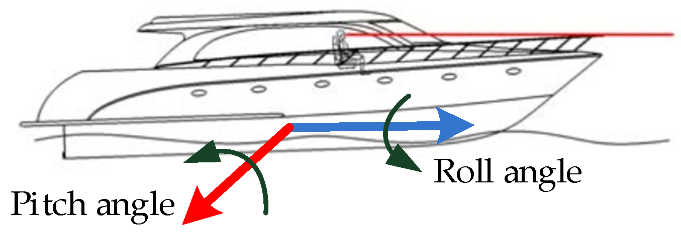
To enhance effectiveness, the simulation utilizes attitude data recorded from USV sailing, which is considered as the external disturbance from the base. The definitions of the pitch and roll angles of the USV are depicted in Figure 4.
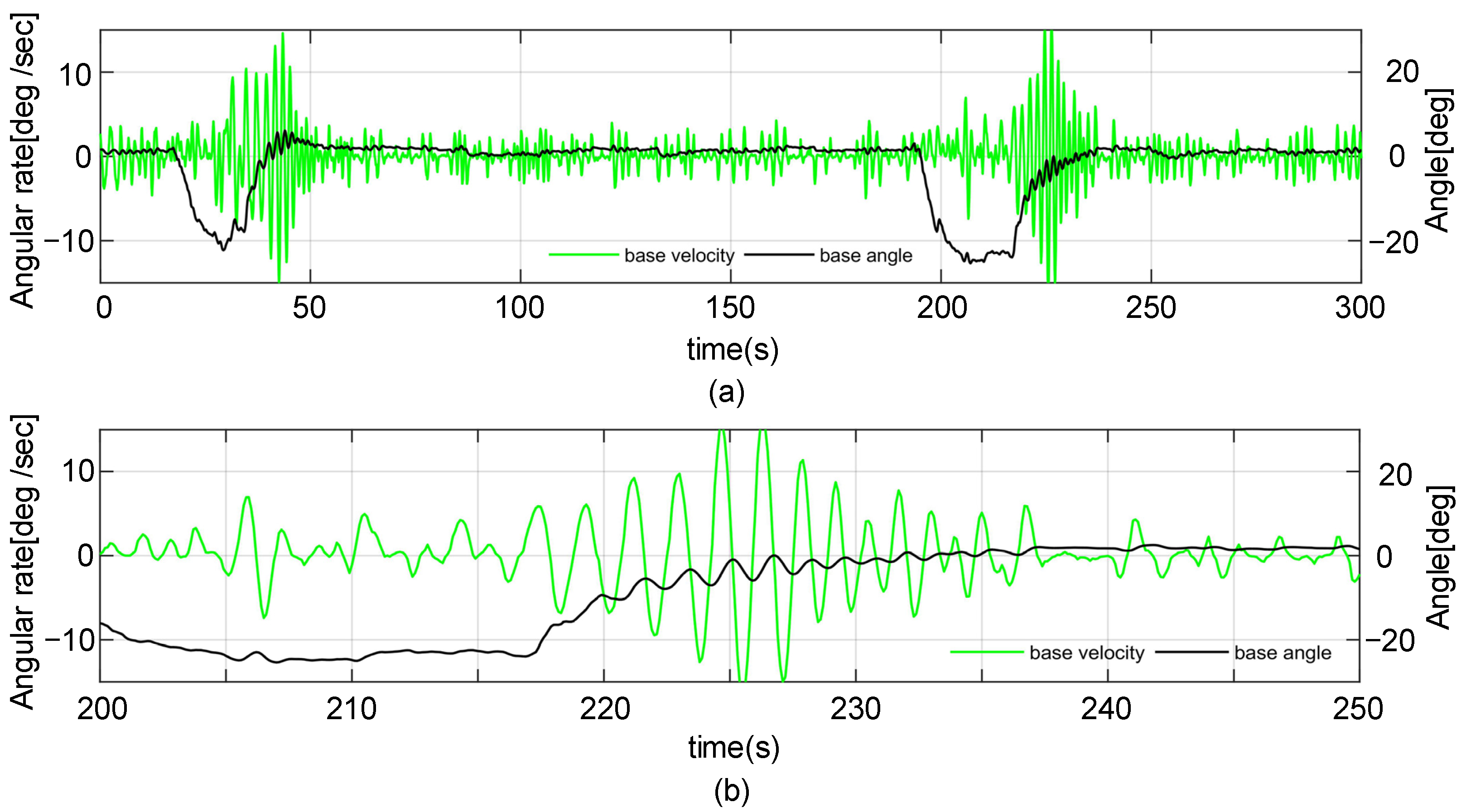
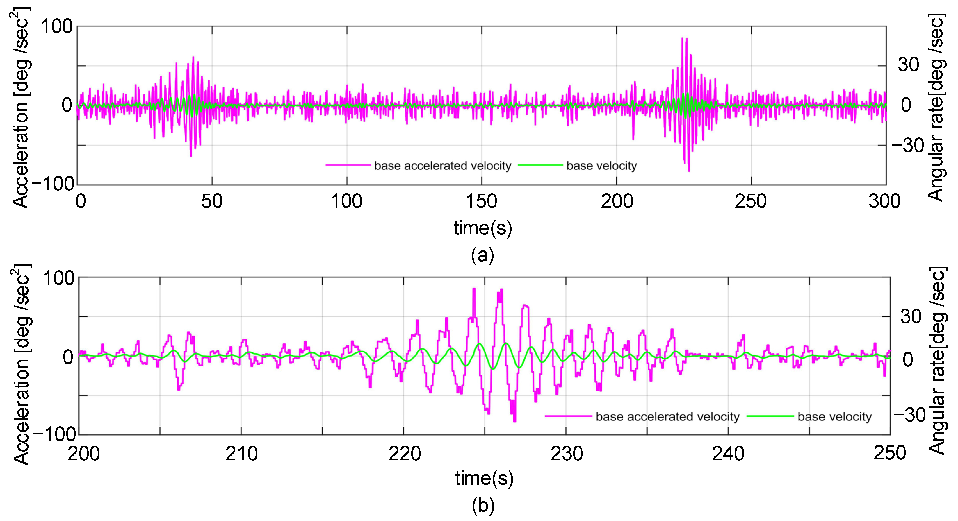
The data describe two instances of the USV’s instantaneous acceleration during sailing. The trajectory of the angle and angular rate in the pitch axis are depicted in Figure 5. The angular acceleration in the pitch axis during sailing is calculated from the angular rate as shown in Figure 6.
From the recorded data, it can be seen that there are overshoots in the angular rate and acceleration during sailing with instantaneous acceleration. To establish a quantitative relationship between the disturbance and the actuator’s accelerated saturation, the disturbance is quantified by the degree of the accelerated overshoot as defined in Equation (19). According to the USV’s attitude data and for ease of analysis during the simulation, the external disturbance is set as a sinusoidal signal, representing the base velocity combined with only one overshoot in the angular rate. The parameters are specified in Table 1.
α = a b a max a max × 100 % a b > a max 0 a b a max
Therefore, ab represents the absolute value of angular acceleration from the base, where ab = 35°/s2 during the base velocity phase. Consequently, the maximal acceleration values of the actuator are amax = 70°/s2 and ab = amax during the overshoot. This establishes the threshold, where α = 0 when the system operates under normal conditions. Subsequently, α > 0 indicates that the actuator’s accelerated saturation has occurred, and the severity increases with the growth of its value.
The observation bandwidth of the LESO with anti-windup compensation is designed at 0.5 kHz, and the operation update rate is 1 kHz. Consequently, the LESO bandwidth is set as ωe = 0.5. Referring to Equation (12), the gains of the LESO can be adjusted in Table 2.
The gains of controller K, which can be determined using the matrixes presented in Section 3.3, represent the matrixes inequalities presented in Equations (17) and (18). These can be solved using the YALMIP tools.
The actuator coefficient is km = 0.00432. Combining the bandwidth of the actuator operation, set at 0.1 kHz, we determined the gain b0 = 0.432 for the system model. Based on the optimized results obtained using the YALMIP tools, as shown in Table 3, the gains can be determined as γ = 0.8.
To simplify the process of acquiring the observed total disturbance, the gain of the anti-windup compensator was set as ja = l3 jq. The observed total disturbance was equal to z ˙ 3 = l3(εjq q), which means that the saturation feedback, q, can be regarded as an adjustment value to the observed error, ε, in the state x3.

4.2. Simulations in the Normal Condition

The system operated within the limitation of the acceleration during an overshoot. The output angular rate of the actuator compensates for disturbances from the base, as shown in Figure 7.
In Figure 8a, the control signal of the actuator, u, is a combination of the tracking output, u0, and observed disturbance variable, z3. The equation usat(u) served as feedback for accelerated saturation and remained at 0 throughout the test. However, vibrations in the control signal, u, were observed at the beginning when the overshoots were introduced. Nonetheless, the LOS vibrations are no more than 1 °/s during the overshoots, as illustrated in Figure 8b.

4.3. Simulations under Acceleration-Limitated Conditions

4.3.1. Immediate Activation Method

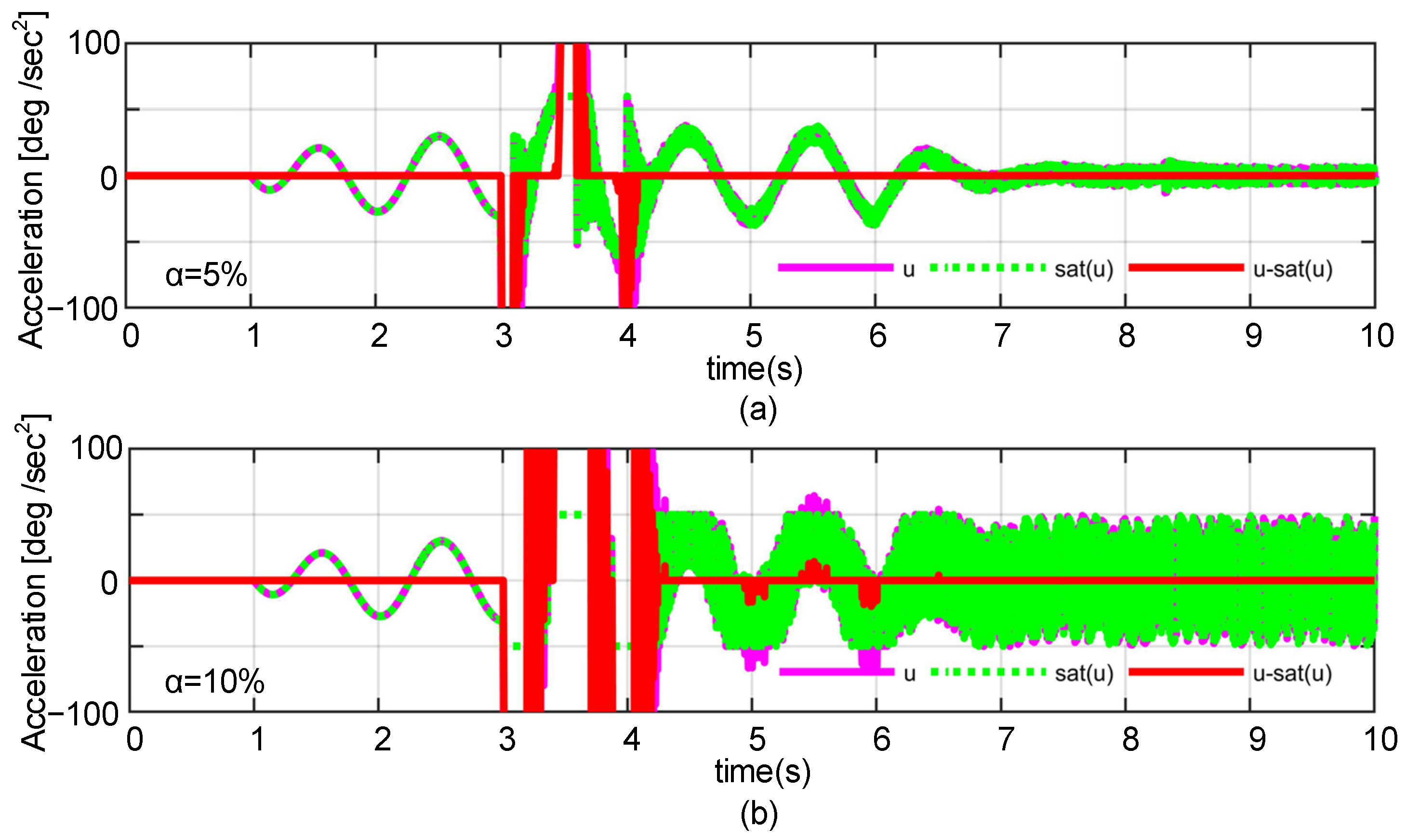
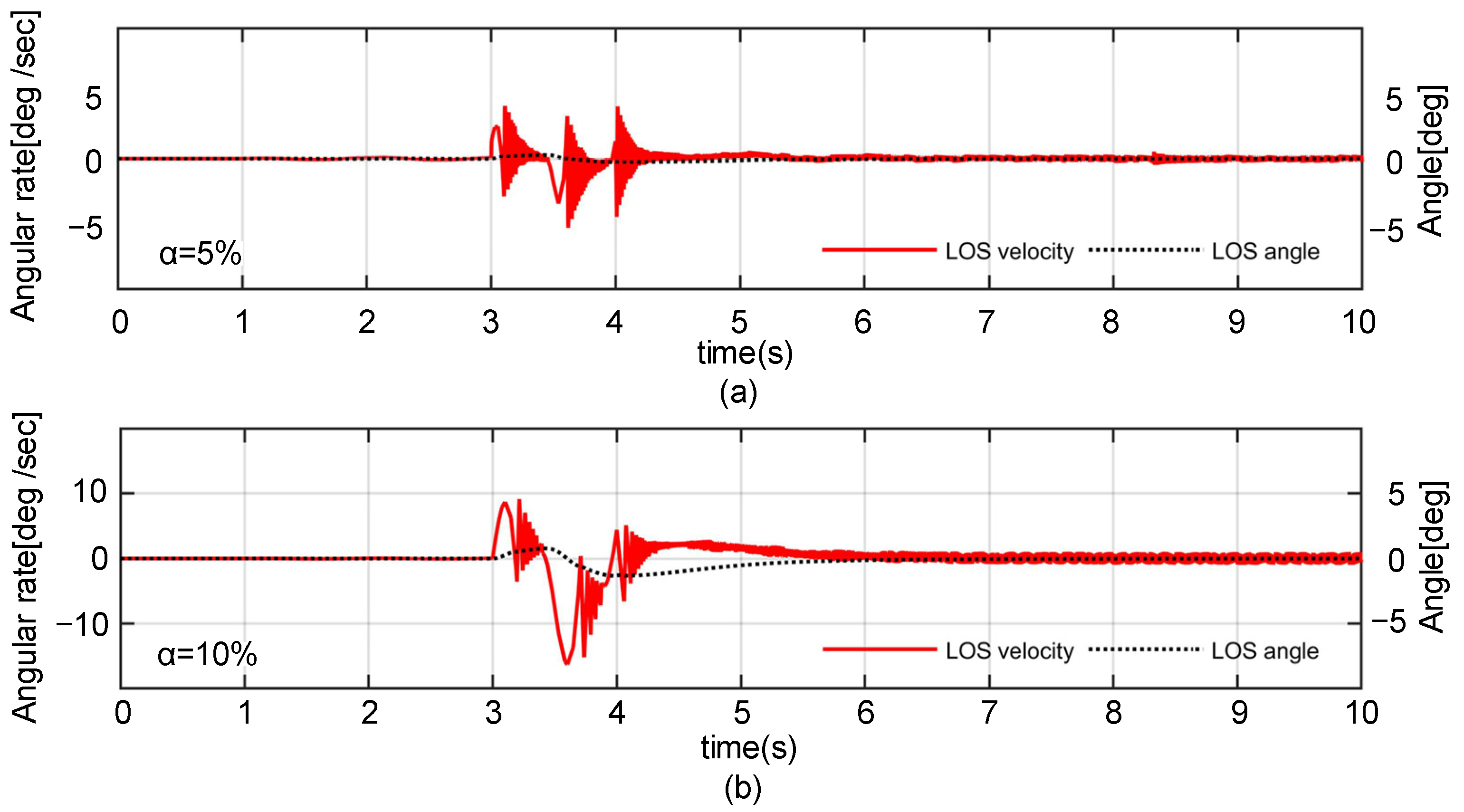
According to the recorded data, overshoots are alternately set at α = 5% and α = 10%, while the system operates under accelerated saturations. Consequently, the maximum accelerations of the overshoots are around 73.5°/s2 and 77.0°/s2, respectively. The LADRC with an anti-windup compensator is configured with an immediate activation model. As shown in Figure 9a, when the overshoot degree is set to α = 5%, the controller output, u, shows vibrations following the introduction of the overshoots, retaining high-frequency vibrations with an amplitude of less than 10°/s2 as the overshoots diminish. Additionally, when α = 10% in Figure 9b, the amplitude of the vibrations reaches almost 50°/s2 as the overshoots diminish. The maximum acceleration value corresponding to the accelerated saturation feedback, q, during this process is 100°/s2, and the data range in all figures is referenced within this value.
As illustrated in Figure 10a, there are attenuated high-frequency vibrations in the angular rate of the LOS during the overshoots, reaching a maximum amplitude of approximately 5°/s when α = 5%. Additionally, at α = 10%, the maximum amplitude reduces to approximately 10°/s, with low-frequency vibrations exceeding 13°/s in Figure 10b. The angle of the LOS is almost 3° during the overshoots. High-frequency vibrations still exist in the angular rate with a low amplitude when the overshoots diminish.

4.3.2. Anticipatory Activation Method

To facilitate the implementation of anticipatory activation for the compensator, the threshold value, us, is proposed and defined as:
λ| ua | ≤ | us | < | ua |, 0 < λ < 1
Hence, the anti-windup compensator operates in three states: normal mode (Model 1), anticipatory activation mode (Model 2), and acceleration-limited mode (Model 3).
Model 1: |u|≤ |us| and q = 0. In this mode, no saturation occurs with the actuator and the tracking system operates as a normal system.
Model 2: |us| < |u| ≤ |ua| and q > 0. In this model, accelerated saturation occurs. The disturbance observation term z3 introduced by the LESO incorporates a saturation feedback term, q, and pre-compensation control is conducted through the stabilized control loop.
Model 3: |u| > |ua|. The system enters a substantial saturation state, where the control input, u, corresponding to the acceleration exceeds the output limit of the actuator. The actuator’s acceleration output remains at its limited value.
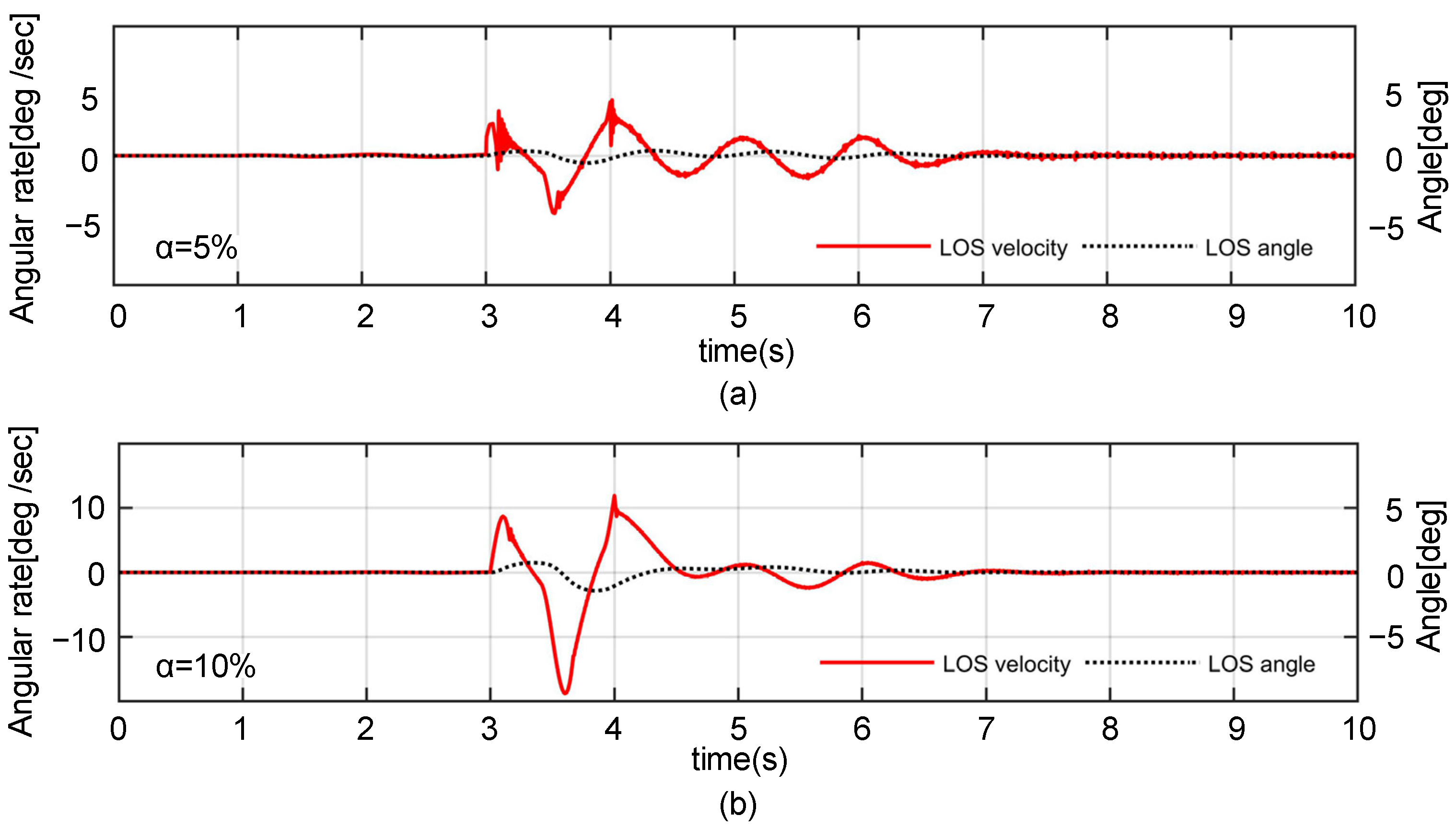
The proposed controller, operating on the LADRC with an anti-windup compensator using an anticipatory activation method, is simulated under the same conditions as the overshoot scenario. The threshold values are set as λ = 0.85 and λ·amax = 59.5°/s. Compared to the immediate activation method, accelerated saturation rarely occurs during the overshoots. These two conditions are demonstrated in Figure 11; when α = 5% and α = 10%, the control signal, u, exhibits a smaller amplitude in vibrations after the overshoots.
According to Figure 12, the high-frequency vibrations in the angular rate of the LOS are weakened in the case of α = 5%, which can lead to an interference in the visual identification. Conversely, for α = 10%, these vibrations are almost eliminated, and the amplitude of low-frequency vibrations remain within 18°/s. Furthermore, there are almost no vibrations in the angular rate.

4.3.3. Simulations with Recorded Attitude Data

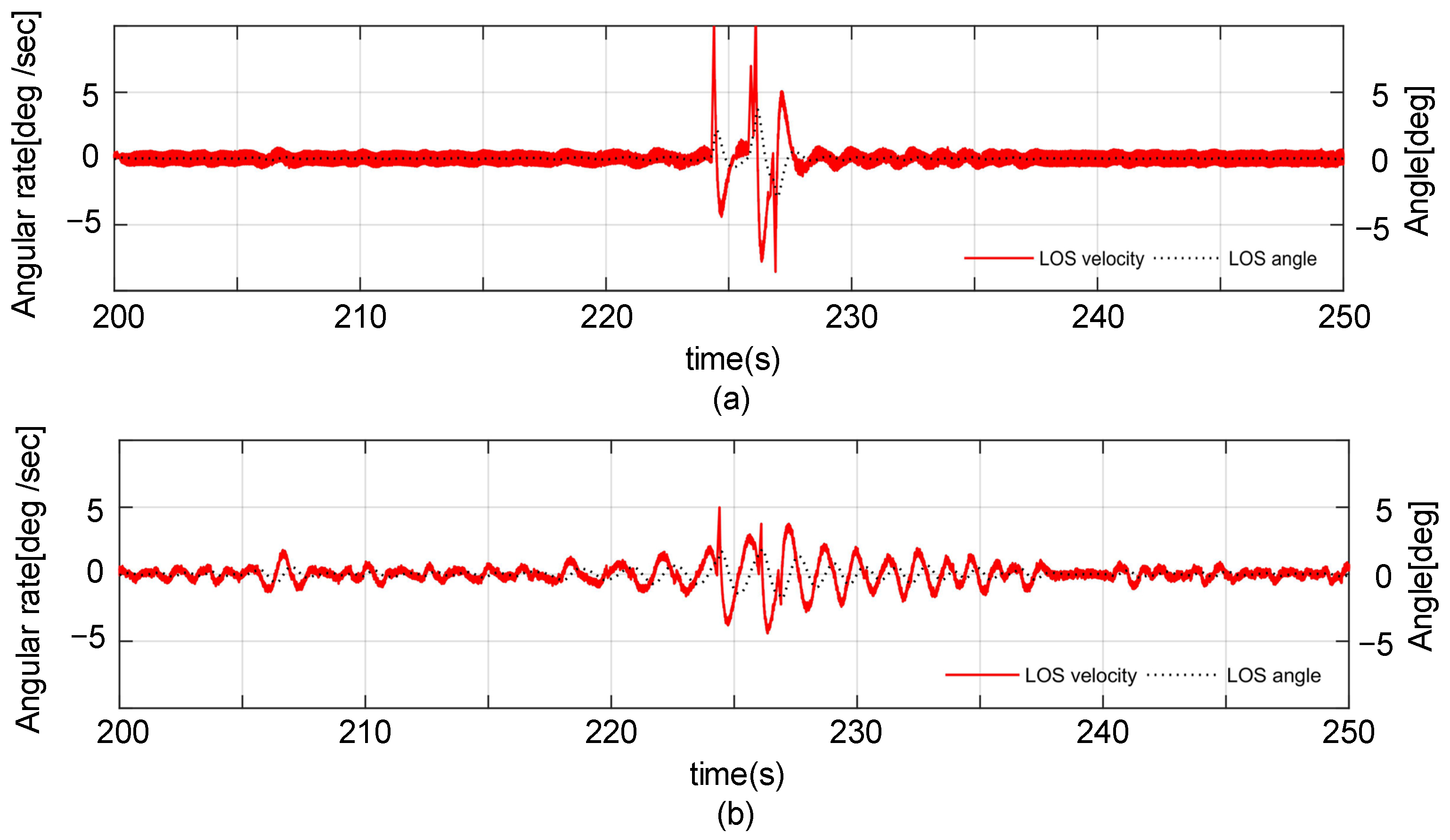
Comparing the simulations based on an individual overshoot in acceleration, it can be seen that the disturbance is introduced by the recorded data from the USV sailing, with results sampled from 200 to 250 s. During the simulation, the value of α ranged from 5% to 10%. According to the results illustrated in Figure 13, when compared to the immediate activation method, the proposed controller exhibits greater stability with the regulation of the accelerated signal, sat(u), and less accelerated saturation, as indicated by usat(u).
The instability of the regulation during the process results in vibrations on the LOS, as illustrated in Figure 14. Low-frequency vibrations on the LOS imply a better quality of identification by the visual sensor mounted on the MISP. The proposed controller avoids high-frequency vibrations during overshoots when compared to the immediate activation method.
The simulation with the recorded data supports the result that the anti-windup controller in the anticipatory activation mode effectively suppresses the high-frequency vibrations in the angular rate of the LOS, which occur due to the accelerated saturation of the actuator in the control process.

5. Experimental Verifications

5.1. Hardware of the Dynamic Camera Platform

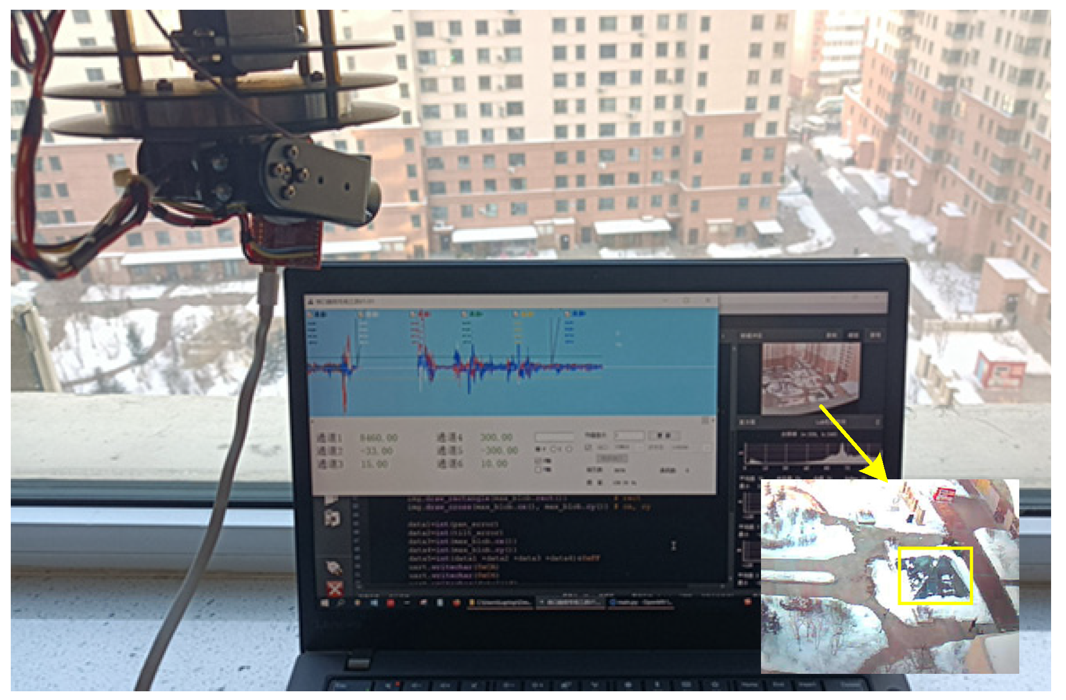
In the visual tracking control for the MISP, the occurrence of high-frequency vibrations in the angular rate of the LOS can lead to several adverse effects, including blurred vision, introduction of disturbances, failure of target identification, and exacerbation of stability issues within the control system. This section aims to assess the performance of the LADRC with an anti-windup compensator on a dynamic camera platform, as illustrated in Figure 15. The controller was evaluated using both anticipatory activation and immediate activation methods, and the obtained results were subjected to comparative analysis.
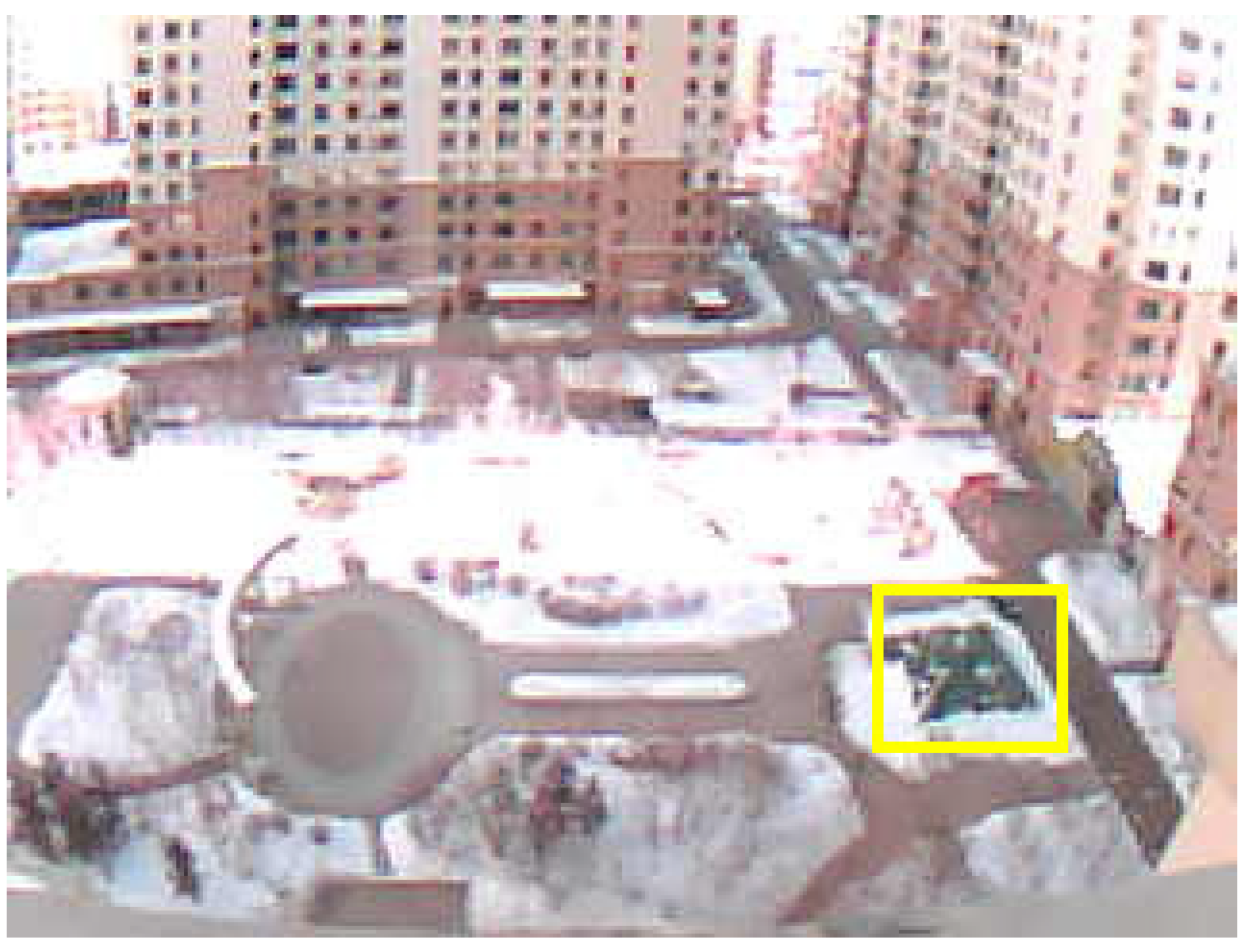
The experiment focused on target tracking in USV-UAV joint operations in a marine environment. The target may be the sea marker or USV for visual navigation. The scenario is simulated with the ground target, and the FOV captured by the visual sensor is depicted in Figure 16. Performance parameters for controlling the platform are outlined in Table 4. The dynamic camera platform was installed on motion equipment capable of simulating the motions experienced during UAV hover or flight modes. This setup provides external disturbances on the base velocity. To approximate the scenario of the recorded date, the base motion was simulated using a sinusoidal velocity curve with a period of 1.2 s, incorporating a 7% random disturbance.
During the initialization of the experiment, the target was identified by a visual sensor and captured at the center of the FOV. There was no base motion acting as the external disturbance until the LOS stabilized. During the experiment, the maximum angular rate reached approximately ±10°/s and the maximum acceleration reached ±75°/s2, equivalent to α = 6.7%. The subsequent experiment results and analysis are detailed below.

5.2. Comparison and Analyses

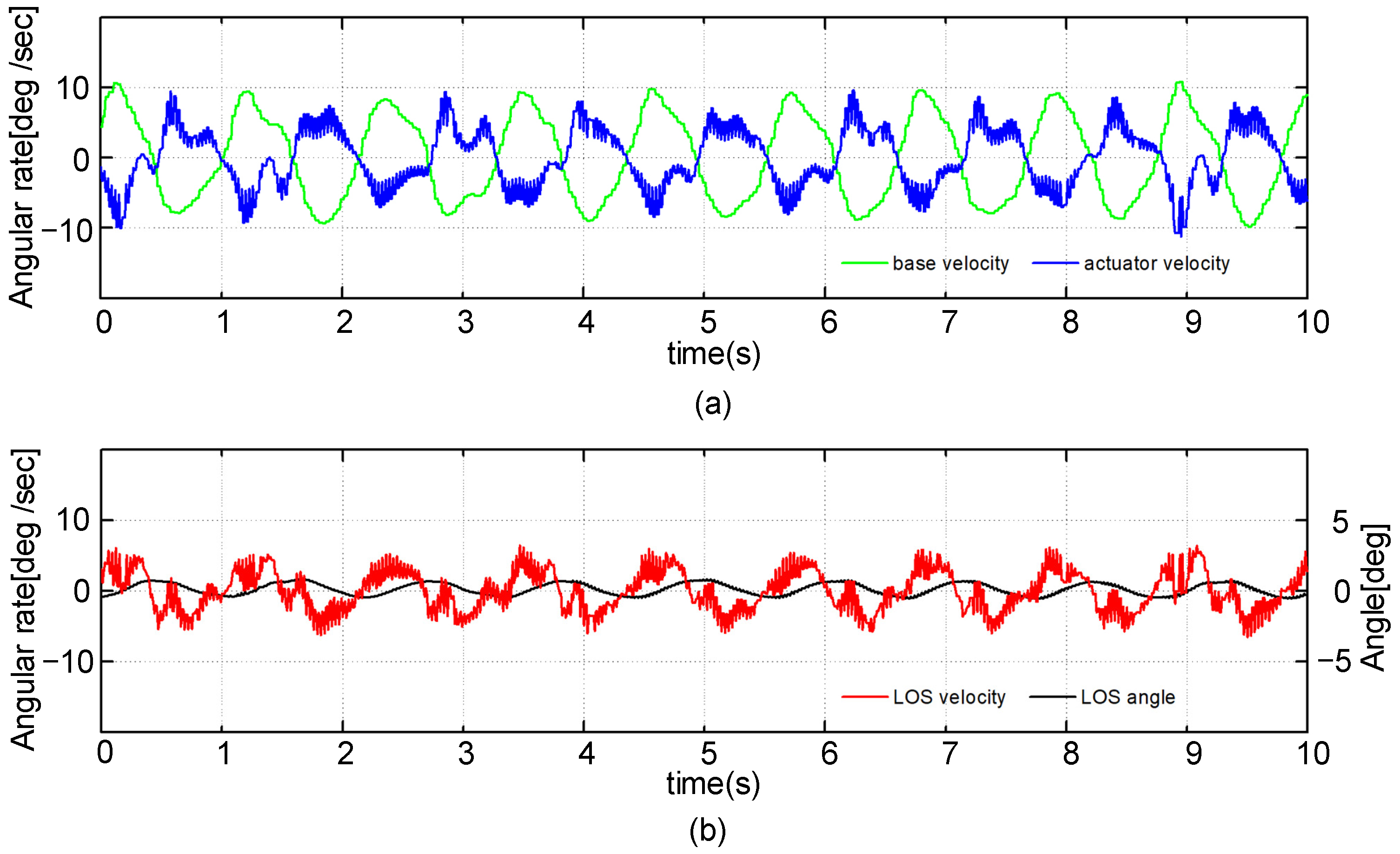
The platform operates under an immediate activation model, compensating for the base velocity, as illustrated in Figure 17a. However, the velocity control loop becomes unstable when the disturbance’s acceleration surpasses the actuator’s threshold value, leading to high-frequency vibrations in the output velocity. Due to physical constraints within the real system, these vibrations converge faster than in simulations. Consequently, the LOS velocity is affected, as depicted in Figure 17b. The velocity vibrations in the LOS significantly reduce the identification performance, as evident in Figure 18. Each screenshot per second from the visual sensor reveals swaying in the FOV. The misidentification of the target renders the visual tracking loop nonfunctional.
For enhancement, the platform incorporates a controller with an anticipatory activation method, showcasing the control performance in Figure 19. Noticeably, the high-frequency vibrations in the velocity-stabilized loop have been significantly suppressed. The actuator’s output effectively compensates for the base velocity to a maximum extent. Consequently, there is a substantial improvement in the stability of the LOS, resulting in sufficient target identification, as illustrated in Figure 20. This reinforces the robustness and stability of the system through the visual tracking loop.

6. Conclusions

In this paper, an anticipatory anti-windup method based on the LADRC has a significant effect on suppressing the high-frequency vibrations on the LOS caused by accelerated actuator saturation. The experimental results of visual tracking for the MISP demonstrate that the target can be identified during low-frequency vibrations with the proposed controller. The robustness of the stabilized control system is ensured through optimization using quadratic programming and an H-infinite performance indicator. As part of the investigation into the multiple activated anti-windup method, the limitations of immediate activation in addressing accelerated saturation have been analyzed through comparisons in the simulations and experiments. The simulations incorporate recorded attitude data from USV sailing as the external disturbance, representing just one scenario of USV sailing. In future work, additional attitude data from various USV sailing cases or UAV cruises will be provided to enhance the credibility of the simulation results. Actual experiments will be conducted in the marine environment for USVs to further validate the proposed method. Additionally, other methods will be explored to address accelerated saturation and optimize the control system.

Author Contributions

T.F. and Y.G. conceived the idea; T.F. designed the software, collected the data, and analyzed the experimental data; L.G. collected the related resources and supervised the experiment; T.F. prepared the original draft and final article; C.Q. proposed the comments for the paper and experiment. All authors have read and agreed to the published version of the manuscript.

Funding

This work is sponsored by the Department of Science and Technology of Heilongjiang Province (2023ZX01A21, LH2021F018), the Science and Technology Research Program of Chongqing Municipal Education Commission (KJZD-K202104701), and the National Natural Science Foundation of China (NSFC.61803118).

Institutional Review Board Statement

Not applicable.

Informed Consent Statement

Not applicable.

Data Availability Statement

Data are contained within the article.

Conflicts of Interest

Author Chao Qin was employed by the company the 54th Research Institute of China Electronics Technology Group Corporation. The remaining authors declare that the research was conducted in the absence of any commercial or financial relationships that could be construed as a potential conflict of interest.

References

  1. Zheng, J.; Chen, J.; Wu, X.; Liang, H.; Zheng, Z.; Zhu, C.; Liu, Y.; Sun, C.; Wang, C.; He, D. Analysis and compensation of installation perpendicularity error in unmanned surface vehicle electro-optical devices by using sea-sky line images. J. Mar. Sci. Eng. 2023, 11, 863. [Google Scholar] [CrossRef]
  2. Lin, C.; Zhang, W.; Shi, J. Tracking strategy of unmanned aerial vehicle for tracking moving target. Int. J. Control Autom. Syst. 2021, 19, 2183–2194. [Google Scholar] [CrossRef]
  3. Helgesen, H.; Leira, F.; Fossen, T.; Johansen, T. Tracking of ocean surface objects from unmanned aerial vehicles with a pan/tilt unit using a thermal camera. J. Intell. Robot. Syst. 2018, 91, 775–793. [Google Scholar] [CrossRef]
  4. Lee, D.; Tran, D.; Kim, Y.; Chakir, S. A robust double active control system design for disturbance suppression of a two-axis gimbal system. Electronics 2020, 9, 1638. [Google Scholar] [CrossRef]
  5. Lu, W.; Niu, C.; Lan, C.; Liu, W.; Wang, S.; Yu, J.; Hu, T. High-Quality Object Detection Method for UAV Images Based on Improved DINO and Masked Image Modeling. Remote Sens. 2023, 15, 4740. [Google Scholar] [CrossRef]
  6. Liu, Y.; Bai, J.; Wang, G.; Wu, X.; Sun, F.; Guo, Z.; Geng, H. UAV Localization in Low-Altitude GNSS-Denied Environments Based on POI and Store Signage Text Matching in UAV Images. Drones 2023, 7, 451. [Google Scholar] [CrossRef]
  7. Wang, P.; Liu, R.; Tian, X.; Zhang, X.; Qiao, L.; Wang, Y. Obstacle avoidance for environmentally-driven USVs based on deep reinforcement learning in large-scale uncertain environments. Ocean Eng. 2023, 270, 113670. [Google Scholar] [CrossRef]
  8. Huang, F.; Chen, X.; Xu, Y.; Yang, X.; Chen, Z. Immersive virtual simulation system design for the guidance, navigation and control of unmanned surface vehicles. Ocean Eng. 2023, 281, 114884. [Google Scholar] [CrossRef]
  9. Zhou, Z.; Jing, Z.; Wang, Q.; Qu, C. Object detection and tracking of unmanned surface vehicles based on spatial-temporal information fusion. J. Electron. Inf. Technol. 2021, 43, 1698–1705. [Google Scholar]
  10. Cortes-Vega, D.; Alazki, H.; Rullan-Lara, J. Visual odometry-based robust control for an unmanned surface vehicle under waves and currents in a urban waterway. J. Mar. Sci. Eng. 2023, 11, 515. [Google Scholar] [CrossRef]
  11. Lee, J.; Yoon, S.; Kim, B.; Gwon, G.; Kim, I.; Jung, H. A new image-quality evaluating and enhancing methodology for bridge inspection using an unmanned aerial vehicle. Smart Struct. Syst. 2021, 27, 209–226. [Google Scholar]
  12. Kwak, J.; Lee, S.; Baek, J.; Chu, B. Autonomous UAV Target Tracking and Safe Landing on a Leveling Mobile Platform. Int. J. Precis. Eng. Manuf. 2022, 23, 305–317. [Google Scholar] [CrossRef]
  13. Park, H.; Chakir, S.; Kim, Y.; Huynh, T. A nonlinear backstepping controller design for high-precision tracking applications with input-delay gimbal systems. J. Mar. Sci. Eng. 2021, 9, 530. [Google Scholar] [CrossRef]
  14. Chen, C.; Liu, D.; Du, J.; Li, Y. Research on Visual Perception for Coordinated Air-Sea through a Cooperative USV-UAV System. J. Mar. Sci. Eng. 2023, 11, 1978. [Google Scholar] [CrossRef]
  15. Wang, Y.; Liu, W.; Liu, J.; Sun, C. Cooperative USV-UAV marine search and rescue with visual navigation and reinforcement learning-based control. ISA Trans. 2023, 137, 222–235. [Google Scholar] [CrossRef]
  16. Cho, G.; Choi, J.; Bae, G.; Oh, H. Autonomous ship deck landing of a quadrotor UAV using feed-forward image-based visual servoing. Aerosp. Sci. Technol. 2022, 130, 107869. [Google Scholar] [CrossRef]
  17. Mu, S.; Qiao, C. Ground-Target Geo-Location Method Based on Extended Kalman Filtering for Small-Scale Airborne Electro-Optical Platform. Acta Opt. Sin. 2019, 39, 0528001. [Google Scholar]
  18. Tullu, A.; Hassanalian, M.; Hwang, H. Design and Implementation of Sensor Platform for UAV-Based Target Tracking and Obstacle Avoidance. Drones 2022, 6, 89. [Google Scholar] [CrossRef]
  19. Opromolla, R.; Fasano, G. Visual-based obstacle detection and tracking, and conflict detection for small UAS sense and avoid. Aerosp. Sci. Technol. 2021, 119, 107167. [Google Scholar] [CrossRef]
  20. Kim, J. Autonomous rover guidance and localization by measuring the peak of a tall landmark. Asian J. Control 2022, 24, 2140–2152. [Google Scholar] [CrossRef]
  21. Warren, M.; Greeff, M.; Patel, B.; Collier, J.; Schoellig, A.P.; Barfoot, T.D. There’s No Place Like Home: Visual Teach and Repeat for Emergency Return of Multirotor UAVs During GPS Failure. IEEE Robot. Autom. Lett. 2019, 4, 161–168. [Google Scholar] [CrossRef]
  22. Rebello, J.; Li, C.; Waslander, S.L. DC-VINS: Dynamic Camera Visual Inertial Navigation System with Online Calibration. In Proceedings of the 2021 IEEE International Conference on Computer Vision Workshops, Electr Networks, Montreal, BC, Canada, 11–17 October 2021. [Google Scholar]
  23. Han, J. From PID to Active Disturbance Rejection Control. IEEE Trans. Ind. Electron. 2009, 56, 900–906. [Google Scholar] [CrossRef]
  24. Gao, Z. Scaling and bandwidth-parameterization based controller tuning. In Proceedings of the 2003 American Control Conference, Denver, CO, USA, 4–6 June 2003. [Google Scholar]
  25. Shao, X.; Wang, H. Active disturbance rejection based trajectory linearization control for hypersonic reentry vehicle with bounded uncertainties. ISA Trans. 2015, 54, 27–38. [Google Scholar] [CrossRef]
  26. Ran, M.; Wang, Q.; Dong, C. Anti-windup design for uncertain nonlinear systems subject to actuator saturation and external disturbance. Int. J. Robust Nonlinear Control 2016, 26, 3421–3438. [Google Scholar] [CrossRef]
  27. Ran, M.; Wang, Q.; Dong, C. Stabilization of a class of nonlinear systems with actuator saturation via active disturbance rejection control. Automatica 2016, 63, 302–310. [Google Scholar] [CrossRef]
  28. Geng, X.; Hao, S.; Liu, T.; Wang, Q. Anti-windup design for discrete-time systems with time delay via predictor-based extended state observer. In Proceedings of the 2019 IEEE International Conference on Control and Automation, Edinburgh, UK, 16–19 July 2019; pp. 1161–1166. [Google Scholar]
  29. Geng, X.; Liu, T.; Hao, S.; Zhong, C.; Wang, Q. Anti-windup design of active disturbance rejection control for sampled systems with input delay. Int. J. Robust Nonlinear Control 2019, 30, 1311–1327. [Google Scholar] [CrossRef]
  30. Geng, X.; Wang, Z.; Hao, S.; Liu, T.; Nagy, Z. Anti-windup Disturbance Rejection Control Design for Sampled Systems with Output Delay and Asymmetric Actuator Saturation Constraint. In Proceedings of the 21st IFAC World Congress on Automatic Control, Electr Networks, Berlin, Germany, 11–17 July 2020. [Google Scholar]
  31. Hao, S.; Liu, T.; Geng, X.; Wang, Y. Anti-windup ADRC design for temperature control systems with output delay against asymmetric input constraint. ISA Trans. 2023, 137, 519–530. [Google Scholar] [CrossRef] [PubMed]
  32. Yu, L.; Sun, X.; Gao, Y. Active Disturbance Rejection Control for Uncertain Nonlinear Systems Subject to Magnitude and Rate Saturation: Application to Aeroengine. IEEE Trans. Syst. Man Cybern.-Syst. 2022, 52, 2201–2212. [Google Scholar] [CrossRef]
  33. Wang, H.; Zuo, Z.; Wang, Y.; Yang, H. Composite Nonlinear Path-Following Control for Unmanned Ground Vehicles with Anti-Windup ESO. IEEE Trans. Syst. Man Cybern.-Syst. 2022, 52, 5865–5876. [Google Scholar] [CrossRef]
  34. Wen, S.; Pan, Z.; Liu, K.; Sun, X. Practical Anti-windup for Open-Loop Stable Systems Under Magnitude and Rate Constraints: Application to Turbofan Engines. IEEE Trans. Ind. Electron. 2023, 70, 4128–4137. [Google Scholar] [CrossRef]
  35. Wu, X.; Lin, Z. On Immediate, Delayed and Anticipatory Activation of Anti-Windup Mechanism: Static Anti-Windup Case. IEEE Trans. Autom. Control 2012, 57, 711–777. [Google Scholar]
  36. Wu, X.; Lin, Z. Dynamic anti-windup design in anticipation of actuator saturation. Int. J. Robust Nonlinear Control 2014, 24, 295–312. [Google Scholar] [CrossRef]
  37. Wu, X.; Pang, J.; Yang, T. Anti-windup Design for Active Disturbance Rejection Control. In Proceedings of the 2014 33rd Chinese Control Conference (CCC), Nanjing, China, 28–30 July 2014; pp. 2389–2395. [Google Scholar]
  38. Wu, X.; Meng, Z.; Cao, P.; Cai, K. A Multiple Activation Anti-windup Design for Systems with Input Saturation and Dead-zone: Experiments on A Satellite Receiver. In Proceedings of the 2016 35th Chinese Control Conference, Chengdu, China, 27–29 July 2016; pp. 1152–1157. [Google Scholar]
  39. Liang, K.; Lin, X.; Chen, Y.; Zhang, W.; Li, J. Robust adaptive multistage anti-windup dynamic surface control for dynamic positioning ships with mismatched disturbance. J. Frankl. Inst.-Eng. Appl. Math. 2021, 358, 2253–2278. [Google Scholar] [CrossRef]
  40. Le, D.; Ngo, M.; Dang, V.; Nguyen, T. A sensorless anti-windup speed control approach to axial gap bearingless motors with nonlinear lumped mismatched disturbance observers. ISA Trans. 2023, 138, 408–431. [Google Scholar] [CrossRef]
Figure 1. The model of accelerated saturation.
Jmse 12 00616 g001
Figure 2. Stabilized control loop with accelerated saturation actuators.
Jmse 12 00616 g002
Figure 3. Visual tracking system based on an LADRC with an anti-windup compensator.
Jmse 12 00616 g003
Figure 4. The axes of attitude angles of the USV.
Jmse 12 00616 g004
Figure 5. Recorded attitude data of the UAV for pitch angle and angular rate: (a) complete data of angle and angular rate; (b) data for 50 s.
Jmse 12 00616 g005
Figure 6. Trajectory of angular acceleration obtained from the angular rate: (a) complete data of acceleration; (b) data for 50 s.
Jmse 12 00616 g006
Figure 7. Angular rate of the actuator while compensating for the disturbance from the base.
Jmse 12 00616 g007
Figure 8. The system is simulated within the constraints of acceleration: (a) the accelerated control signal of the actuator; (b) the LOS angle and angular rate during the disturbance without saturation.
Jmse 12 00616 g008
Figure 9. The control signal and saturation quality with the immediate activation method: (a) the accelerated overshoot is 5%; (b) the accelerated overshoot is 10%.
Jmse 12 00616 g009
Figure 10. High-frequency vibrations of the LOS in angle and angular rate with the immediate activation method: (a) the accelerated overshoot is 5%; (b) the accelerated overshoot is 10%.
Jmse 12 00616 g010
Figure 11. The control signal and saturation quality with the anticipatory activation method: (a) the accelerated overshoot is 5%; (b) the accelerated overshoot is 10%.
Jmse 12 00616 g011
Figure 12. Vibrations of the LOS in angle and angular rate with anticipatory activation method: (a) the accelerated overshoot is 5%; (b) the accelerated overshoot is 10%.
Jmse 12 00616 g012
Figure 13. Comparison of control signal and saturation quality between different activations: (a) immediate activation; (b) anticipatory activation.
Jmse 12 00616 g013
Figure 14. Comparison of angle and angular rate on the LOS during accelerated saturation: (a) immediate activation; (b) anticipatory activation.
Jmse 12 00616 g014
Figure 15. Dynamic camera platform with test and data acquisition systems.
Jmse 12 00616 g015
Figure 16. The geographical target in the yellow square for tracking in the FOV.
Jmse 12 00616 g016
Figure 17. The system operating under 5~7% accelerated overshoots from the base with the immediate activation method: (a) the angular rate of the actuator during compensation for the base disturbance; (b) vibrations of the LOS in angle and angular rate.
Jmse 12 00616 g017
Figure 18. The geographical target remains unidentified due to the vibrations of the LOS.
Jmse 12 00616 g018
Figure 19. The system operates at 5~7% accelerated overshoots from the base with the anticipatory activation method: (a) the angular rate of the actuator during compensation for the base disturbance; (b) vibrations of the LOS in angle and angular rate.
Jmse 12 00616 g019
Figure 20. The geography target is identified and tracked by the stabilized LOS during the overshoot from the base.
Jmse 12 00616 g020
Table 1. The parameters of the external disturbance from the base.
External DisturbanceMaximal Velocity Maximal AccelerationDuration
base velocity5°/s35°/s28 s
Overshoot10°/s70°/s21 s
Table 2. The gains of the LESO with an operational bandwidth of 1 kHz.
LESO BandwidthGains for LESO
ωe = 0.5l1 = 1.5, l2 = 0.75, l3 = 0.125
Table 3. The gains of the controller, K, with different values of γ.
Gains for KConditions
k1 = 2.1786, k2 = 4.5847, −1/b0 = −2.3115γ = 1.0
k1 = 2.1788, k2 = 4.5852, −1/b0 = −2.3062γ = 0.9
k1 = 2.1790, k2 = 4.5855, −1/b0 = −2.3038γ = 0.8
k1 = 2.1859, k2 = 4.6226, −1/b0 = −1.3038γ = 0.7
k1 = 2.1864, k2 = 4.6237, −1/b0 = −1.3631γ = 0.6
k1 = 2.1870, k2 = 4.6249, −1/b0 = −1.2995γ = 0.5
Table 4. Parameters of the dynamic camera platform.
TermsScope RangeAccuracy
PitchAngular rate±190°/sGyro:0~±250°/s,
131 LSB/(°/s)
Angular acceleration±70°/s2
YawPitch angle speed±170°/sGyro:0~±250°/s,
131 LSB/(°/s)
Yaw angle speed±70°/s2
Visual resolution320 × 2401 pixel
Disclaimer/Publisher’s Note: The statements, opinions and data contained in all publications are solely those of the individual author(s) and contributor(s) and not of MDPI and/or the editor(s). MDPI and/or the editor(s) disclaim responsibility for any injury to people or property resulting from any ideas, methods, instructions or products referred to in the content.