Abstract
This paper examines the response characteristics of a warship’s double-layer plates under a secondary near-field explosion after the ship’s outer plate has been perforated by shaped metal jets. First, the effectiveness of the Coupled Eulerian–Lagrangian (CEL) method was validated, showing numerical simulations to be well aligned with experimental results. Subsequently, the damage inflicted on the outer plate by metal jets was simplified to a prefabricated orifice, further studying the explosive impact response of double-layer plates under different inter-compartmental water levels and charge distances. Our findings indicated the following: (1) shockwave and bubble pulsation loads are the main causes of deformation in the outer plate; (2) the driving of the outer plate and the flooding water between compartments are the main causes of deformation in the inner plate; and (3) deformation in the outer plate will decrease as the water level in the compartment increases, while deformation in the inner plate will increase with the increasing water level. Consequently, under certain specific damage, the ingress of water into a compartment effectively enhances the explosion resistance of the double-layer plates.
1. Introduction
Contemporary warships frequently feature double-layer structures to bolster longitudinal strength and heighten resistance against underwater threats like torpedoes and mines [1,2]. However, the rapid development of underwater weapons has led to the creation of torpedoes armed with both shaped charges and high-explosive warheads [3,4,5]. When attacked by such weapons, high-speed metal jets first penetrate the outer plate, causing initial damage. Subsequently, shockwave and bubble pulsation loads cause secondary damage to the ship’s structure, followed by more severe damage from flooding loads inside the compartments. Even when simplifying the damage from the metal jet as a prefabricated orifice on the outer plate, the transmission of underwater explosion (UNDEX) loads through the damaged double-layer structure, as well as the interaction between bubbles and the double-layer structure, is extremely complex and necessitates detailed study.
Currently, scholars have initiated studies on the interaction between bubbles and boundaries with breaches [6,7,8,9]. For instance, Cui et al. [10] studied the mechanism of interaction between a single bubble generated by electric sparks and a perforated wall, identifying the critical distance at which the bubble moves away from the incomplete boundary. Huang et al. [11] employed the boundary element method to explore the interaction between bubbles and perforated walls, elucidating the mechanism of surge formation within compartments. He et al. [12] used the Eulerian finite element method to investigate the interaction mechanisms between near-field UNDEX bubbles and double-layered breach structures, deriving the dynamics of compartment surging and flow field evolution. Liu et al. [13] conducted experimental research on the jetting characteristics of bubbles under the combined influence of a free liquid surface and a perforated rigid wall, discovering a new phenomenon of upward and downward jetting by the bubbles. Sun et al. [14,15] further extended the single-phase and weakly-compressible δ-SPH model to simulate multi-phase and strongly compressible flows. However, the above scholars’ studies all regarded the breach boundary as a rigid body, and only investigated the motion characteristics of the underwater explosive load near the breach boundary and the dynamic behavior of the bubble-induced breach influx, and there is a lack of research on the elastic–plastic deformation of the double-layer structure and the damage of the inner-plate structure under the action of shockwaves and bubbles. Consequently, it is challenging to accurately reflect the dynamic response of ship structures under the impact of combined warheads in real naval combat.
High-precision numerical simulation techniques are effective in addressing the aforementioned challenges [16,17,18,19]. Several effective numerical models have been developed in current research on fluid–structure interaction during UNDEX [20,21,22,23]. Building on this, researchers have investigated the combined damaging effects of shockwaves and bubble pulsation loads on ships subjected to close-in explosions. For instance, Huang et al. [24] utilized the CEL method to analyze the response of a double-layer structure with an orifice on the outer plate by varying the charge distance, orifice radius, and charge weight, providing insights into new damage patterns in the double-layer structures of ships. Gan et al. [25] considered structural deformations and employed the Coupled Eulerian–Lagrangian (CEL) method to simulate the deformation and failure mechanisms of ship beam structures under close-in UNDEX loads, concluding that the primary cause of deformation in these structures is bubble pulsation. Chen et al. [26] used the ALE method to study the damage characteristics of the double-layer structures of ships under UNDEX loads, providing guidance for ship protection technologies. Zong et al. [27] utilized the acoustic–structure coupling method to investigate the damage to ship structures from close-in UNDEX, identifying three types of damage modes in ships.
Building on the work discussed above, this paper focuses on the double-layer plates of a surface ship with an orifice caused by shaped charge warheads. Section 2 establishes a fluid–structure interaction dynamics model utilizing the CEL method, validated against experimental data. Section 3 analyzes the secondary damage characteristics of the double-layer structure. Finally, Section 4 summarizes the damage characteristics of double-layer plates under various cases.
2. Numerical Model
2.1. CEL Method
The CEL method integrates the advantages of both Eulerian and Lagrangian approaches. The fluid component is analyzed using the Eulerian method, while the stress, strain, and displacement of the structural component are computed using the Lagrangian method. In this approach, the nodes of the Lagrangian elements move synchronously with the material points, whereas the nodes of the Eulerian elements remain fixed in space. The two methods do not interfere with each other but interact solely at the coupling interface, effectively addressing the issues of high impact and large deformations involved in UNDEX. Therefore, the CEL method is well suited for simulating the damage characteristics of double-layer plates.
The specific expressions for the continuity equation, the momentum equation, and the energy conservation equation are as follows [28,29]:
where is the fluid density; is the vector differential operator; v is the velocity vector of the fluid; is the Cauchy stress tensor; b is the unit cohesive force tensor; E represents the energy; denotes the strain rate; and indicates the thermal conductivity.
2.2. Equation of State
2.2.1. Equation of State for Water
A linear Us−Up equation of state is used to simulate the flow of water, accurately modeling the motion of water under the strong shock conditions of UNDEX. The equation of state for water is as follows [28]:
where Em is the specific internal energy of water, is a material constant, is the reference density, is the nominal volume strain, is the density of water, and PH is the Hugoniot pressure, expressed as follows:
where c0, s are coefficients defining the relationship between the linear shockwave velocity Us and particle velocity Up, which is expressed as follows:
Thus, the linear Us−Up state equation is as follows:
The parameters of the state equation for water are illustrated in Table 1.

Table 1.
Parameters of water state equation.
2.2.2. Equation of State for Charge
The detonation products of TNT are described using the JWL (Jones–Wilkins–Lee) equation of state, specified as follows [28]:
where represents the density ratio of the detonation products to the initial explosive; A, B, R1, R2, are constants in the JWL equation describing the state of the explosives; and e is the specific internal energy of the explosive.
The specific parameters are shown in Table 2.
Table 2.
Parameters of the JWL equation of state.
2.2.3. Equation of State for Air
The air within the fluid domain is modeled using the ideal gas equation of state [28]:
where the atmospheric pressure Pa is taken as 101,300 Pa, the adiabatic index is taken as 1.4, and Ea represents the specific internal energy. The air density is assumed to be 1.225 kgm−3.
2.3. Numerical Validation
2.3.1. Plate Structure Damage Verification
To validate the numerical model developed in this study, following the working conditions of the reference [30], we established the numerical model as shown in Figure 1. The charge distance is 0.15 m; the dimensions of the plate are 0.3 m × 0.25 m, with a thickness of 0.002 m, and rigid boundary constraints are applied around the plate’s perimeter. The domain size is 2 m × 2 m × 2 m. Non-reflective boundary conditions are applied, and atmospheric pressure loads are applied in the air domain. To ensure the accuracy of numerical simulations, we set the mesh size of the domain to 0.01 m uniformly, utilizing EC3D8R elements.

Figure 1.
The numerical model.
The material of the plate is Q235 steel, and the Johnson–Cook material model is used to define the constitutive relationship. The specific expression is as follows [31]:
where is the Mises equivalent stress; is the equivalent plastic strain; is the effective plastic strain rate; is the reference strain rate, usually taken as ; A is the yield stress at the reference temperature and strain rate; B and n are strain-hardening coefficients; C and M are material constants representing the coefficients of strain rate hardening and thermal softening; is the room temperature; and is the melting temperature. The parameters used in this paper are listed in Table 3 [32].
Table 3.
The main parameters of Johnson–Cook.
Material failure is modeled using the Johnson–Cook failure model, incorporating the failure parameter D, with the expression as follows [31]:
where and represent the incremental equivalent plastic and instantaneous failure strains, respectively; and D1–D5 are the material failure parameters typically obtained through experimental calculations. The parameters used in this study are listed in Table 4 [32].
Table 4.
Johnson–Cook failure parameters.
This section refers to the experimental conditions from the reference, with the distance between the explosive and the plate fixed. By varying the equivalent weight of the explosive, three cases are set as shown in Table 5. The table uses an “impact factor” to describe the magnitude of the explosive shock load, where m is the weight of the charge and l is the charge distance.
Table 5.
Working condition settings.
Figure 2 presents the numerical simulation results for each cases. It is evident from the figure that there is a good agreement between the experimental and numerical simulation results. In Cases 1 and 2, the plates exhibited upward plastic deformation, while the center of the plate in Case 3 has torn.
Figure 2.
Comparison of experimental [30] and numerical simulation results.
Table 6 shows the comparison of maximum deflection of the plate in experimental and numerical simulations. The error between experimental and simulation values is controlled within 5%, verifying the effectiveness of the CEL method.
Table 6.
Comparison of maximum deflection in tests and numerical simulations.
2.3.2. Convergence Analysis
To validate the rationality of the mesh size chosen for the computational domain, a study on the mesh convergence of underwater explosions with a free liquid surface is conducted. A computational domain model is established (Figure 3), with dimensions of 2 m × 2 m × 2 m. Non-reflective boundary conditions are applied, and atmospheric pressure loads are set in the air domain. The equations of state and material parameters used for air, water, and explosives are consistent with those used in Section 2.3 of this paper. The charge distance is set to 0.2 m, and six different mesh element sizes are selected: 0.01 m, 0.015 m, 0.02 m, 0.025 m, 0.3 m, and 0.35 m. The element type is EC3D8R.
Figure 3.
Computational domain model.
Figure 4 shows the kinetic energy of the flow field. With the explosion initiation, the shockwave load rapidly escalates the kinetic energy of the flow field, which gradually stabilizes with bubble pulsation. With the refinement of the mesh, the kinetic energy of the computational domain shows an increasing trend. When the mesh size is less than 0.02 m, the rate of kinetic energy increase diminishes, signaling convergence within the computational domain. There is little difference in the kinetic energy of the computational domain between mesh sizes of 0.01 m and 0.015 m, and reducing the mesh size will prolong the computation time. Balancing computation time and accuracy, a mesh size of 0.015 m is determined optimal for the computational domain.
Figure 4.
Evolution of kinetic energy in computational domain under different mesh sizes.
2.4. Simplified Model of Double-Layer Plates
2.4.1. Numerical Model
The computational domain size was set to 2 m × 2 m × 2 m with non-reflective boundary conditions, and the explosive was placed at the center of the domain. The outer plate was 1 m × 1 m with a thickness of 0.002 m, and had an orifice with an radius of 0.02 m (Figure 5a). The inner plate was also 1 m × 1 m with a thickness of 0.002 m (Figure 5b).
Figure 5.
Schematic diagram of the outer (a) and inner plates (b).
Both inner and outer plates are made of Q235 steel, and the constitutive relationship is defined using the Johnson–Cook material model, while material failure is defined using the Johnson–Cook failure model. The specific expressions remain consistent with those used in Section 2.3.1.
The parameters of the Johnson–Cook material model and Johnson–Cook failure model are shown in the Table 7 and Table 8 [33].
Table 7.
The main parameters of Johnson–Cook.
Table 8.
Johnson–Cook failure parameters.
2.4.2. The Parameters
To more accurately simulate the dynamic response of double-layer plates under UNDEX loads, a numerical model as shown in Figure 6 was established. The model takes into account the flooding of the compartment following the orifice of the outer plate by the shaped charge warheads. In the model, l denotes the water level height within the compartment of the double-layer plates, h the spacing between the inner and outer plates, d the charge distance, and Rd the radius of the orifice. To analyze the process from no water in the compartments to the compartments being filled with water and from a close-range explosion to a contact explosion, respectively, the working conditions are set as shown in Table 9.
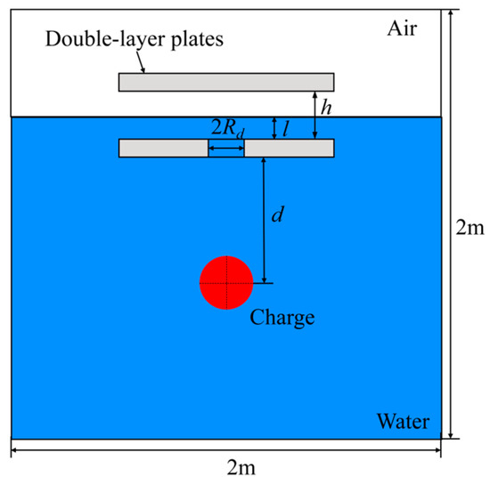
Figure 6.
Schematic diagram of the numerical model.
Table 9.
Working condition settings.
The actual separation between the inner and outer plates of the ship is approximately 1.5 m, which we scaled down by a factor of 10 and applied to the model used in this paper. In actual situations, the radius of the orifice caused by the penetration of the ship’s hull by the shaped charge warhead can reach up to 0.2 m [5]. Based on this, we set the prefabricated orifice radius to 0.02 m according to the scaling ratio.
3. Results and Discussions
3.1. Basic Characteristics
We selected Case 2, with a charge of 0.4 kg, d = 0.2 m, l = 0 m, h = 0.15 m, and Rd = 0.02 m, as the basic working conditions for analyzing the damage characteristics of the inner and outer plates. Figure 7 shows the numerical simulation results for this case.
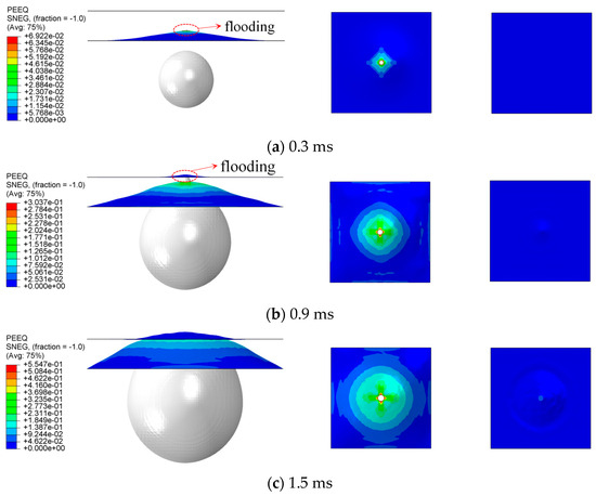
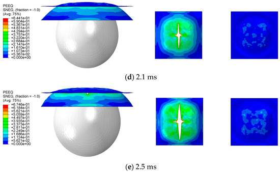
Figure 7.
Numerical simulation results for Case 2.
From Figure 7a, at t = 0.3 ms, the outer plate undergoes upward plastic deformation due to shockwave loads. Since the compartment is filled with air, the shockwave load is significantly attenuated upon transmission to the inner plate, thus causing negligible deformation. At t = 0.9 ms, as shown in Figure 7b, the deformation of the outer plate further increases due to bubble pulsating loads. Simultaneously, water surges through the orifice in the outer plate, imposing flooding loads on the inner plate, inducing upward plastic strain. Concurrently, as the bubble expands, the deformation of both the inner and outer plates increases. At t = 1.5 ms, as shown in Figure 7c, significant deformation of the outer plate leads to contact with the inner plate, causing it to deform as well. At t = 2.1 ms, as shown in Figure 7d, the bubble has made direct contact with the double-layer plates. Under the effect of bubble pulsating loads, the central region of the outer plate has been torn, resulting in a petal-shaped breach. At t = 3 ms, following contact between inner and outer plates, plastic strain in the surrounding areas of the outer plate influences the inner plate, increasing the plastic strain in both plates around these areas. Additionally, the central breach in the outer plate further enlarges.
In summary, as the compartment lacks water, the outer plate absorbs nearly the entirety of the shockwave load, leading to significant deformation and a petal-shaped breach in the central region. Initially, the inner plate exhibits a minor degree of plastic strain under the impact of flooding loads. Subsequently, driven by the deformation of the outer plate, the plastic strain in the inner plate also increases.
3.2. The Effect of Different Parameters
3.2.1. Effect of Water Levels
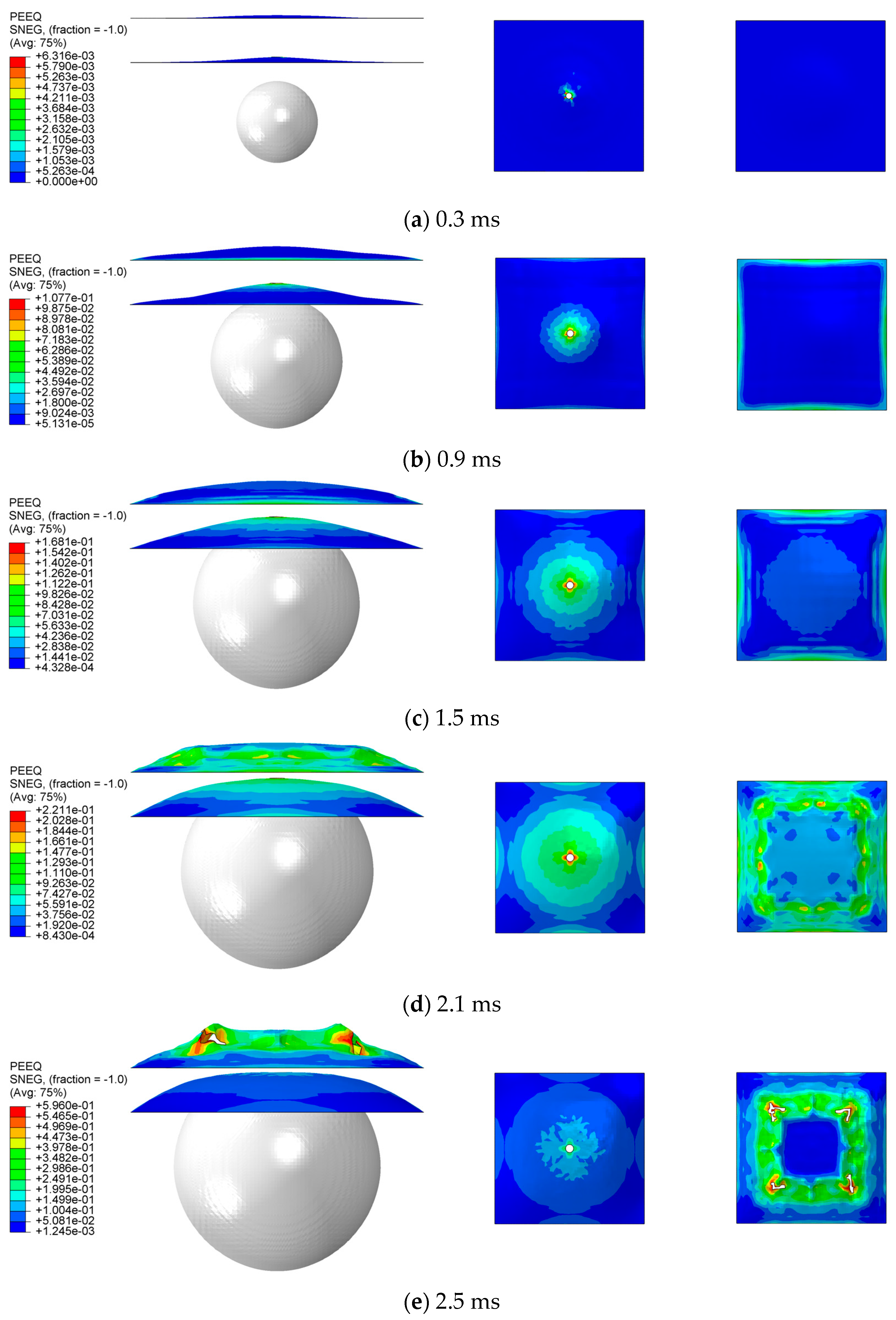
From Section 3.1, it is evident that the water level has a significant impact on the transmission of impact loads. Therefore, this section investigates the influence of the water level inside the compartment on the damage characteristics of the double-layer plates. Based on Case 2, while keeping other parameters such as charge distance constant, different water levels inside the compartment were set for Cases 3, 4, and 5 as presented in Table 7, where the water levels inside the compartment are 0.05 m, 0.1 m, and 0.15 m, respectively. Figure 8 shows the numerical simulation results for Case 5.
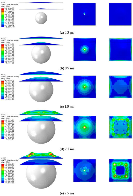
Figure 8.
Numerical simulation results for Case 5.
As shown in Figure 8a, at t = 0.3 ms, both inner and outer plates exhibit varying degrees of plastic strain. In comparison to Figure 7a, the deformation of the outer plate is decreased in this case. This reduction is attributed to the compartment being filled with water, enabling the transmission of the impact loads through the water medium to the inner plate. Consequently, it reduces the outer plate’s deformation while inducing plastic strain in the inner plate. Subsequently, as shown in Figure 8b–d, driven by bubble pulsation loads, flooding within the compartment imposes impact loads on the outer plate, causing its plastic strain to gradually increase. Additionally, the deformation of the outer plate in this case is reduced, with no contact between the inner and outer plates. This reduction is due to the shockwave and bubble pulsation loads transmitted through the water medium to the inner plate, which also partially restricts the deformation of the outer plate. Finally, as shown in Figure 8e, with the ongoing expansion of the bubble, at t = 2.5 ms, the center region of the inner plate reaches its maximum degree of plastic strain under the impact of the flooding load within the compartment. As the bubble has a relatively low internal pressure, the pulsating pressure in the upper bubble domain is significantly lower than the atmospheric pressure. Consequently, some sinking deformations occur around the region of maximum deformation of the inner plate, resulting in four evenly distributed breaches on the plate.
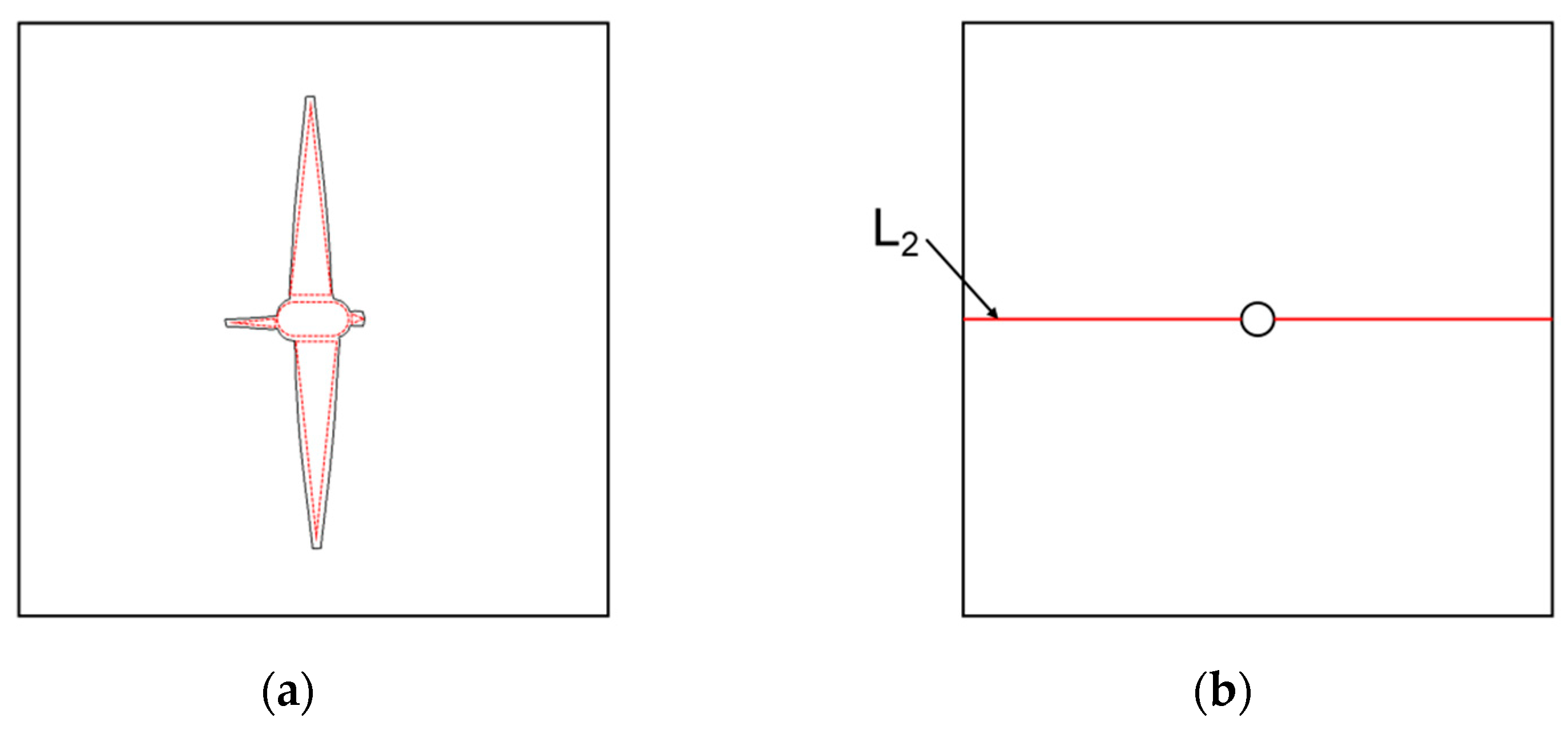
Below, the damage characteristics of the double-layer plates under four cases are summarized. As shown in Figure 9, an observation line L1 is placed on the central axis of the inner plate for deflection distribution extraction, and an observation point P1 is set at the center of the inner plate to extract the deflection history curve. Then, as shown in Figure 10, the petal-shaped breach was simplified, dividing it into an elliptical area and four triangular areas to determine the area of the breach. Subsequently, a reference line L2 was placed on the central axis of the outer plate to extract the deflection distribution.
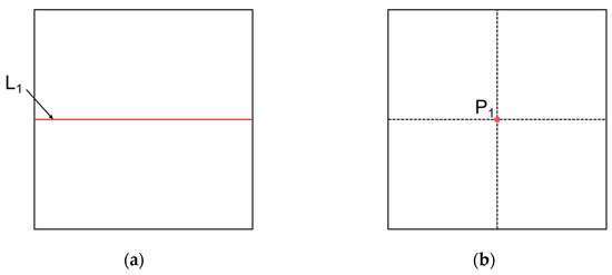
Figure 9.
Setting of observation line (a) and observation point of the inner plate (b).
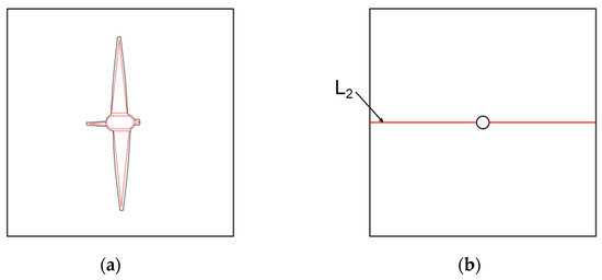
Figure 10.
Simplification of outer plate breaches (a) and setting of observation line (b).
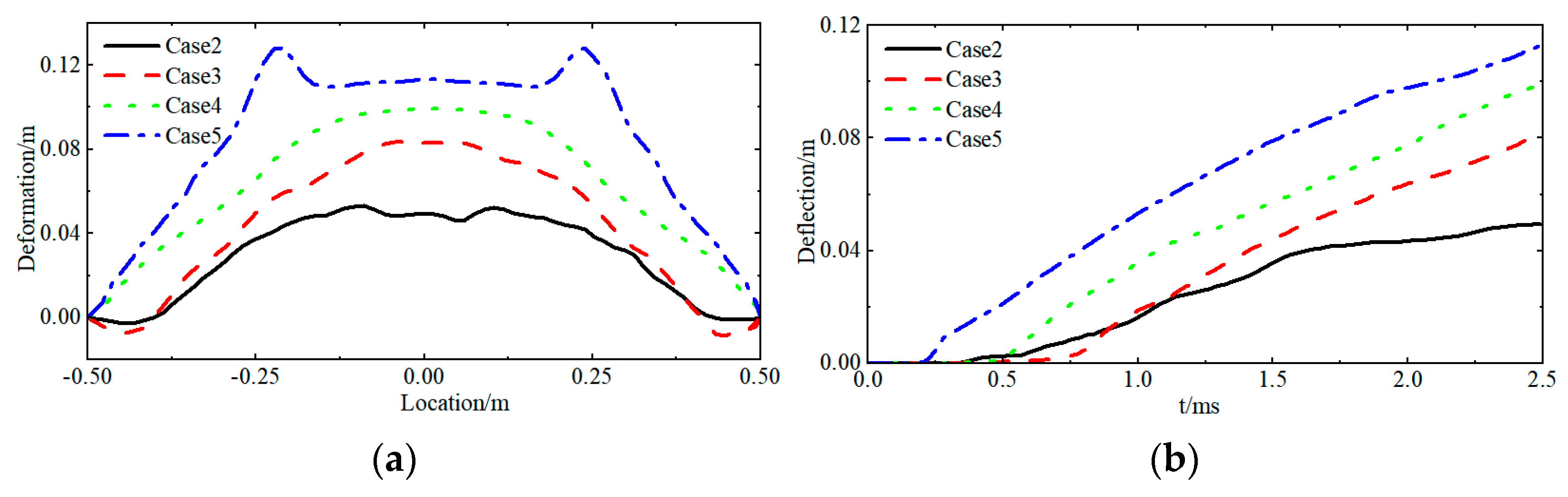
Figure 11 shows the deflection distribution along the central axis of the inner plate at t = 2.5 ms, as well as the deflection history curve. These figures reveal that all cases resulted in upward plastic strain in the inner plate due to flooding loads between compartments, with deflection increasing as the water level rose. This increase is due to the reduced attenuation of shockwave and bubble pulse loads through the water medium between compartments as the water level rises, resulting in a gradual increase in the impact load on the inner plate, thereby increasing its deflection. In the later stages of bubble pulsation, the inner plate’s deformation rate decreases due to the significantly lower internal pressure of the bubble compared to atmospheric pressure. Influenced by atmospheric pressure, it can be seen from the deflection distribution along the central axis that all cases resulted in compressive damage, showing regions of sinking deformation on the inner plates.
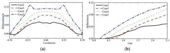
Figure 11.
Deflection of the inner plate in cases 2, 3, 4, and 5. (a) At the final stage (t = 2.5 ms) along the center axis; (b) Time history curve of the deflection at P1.
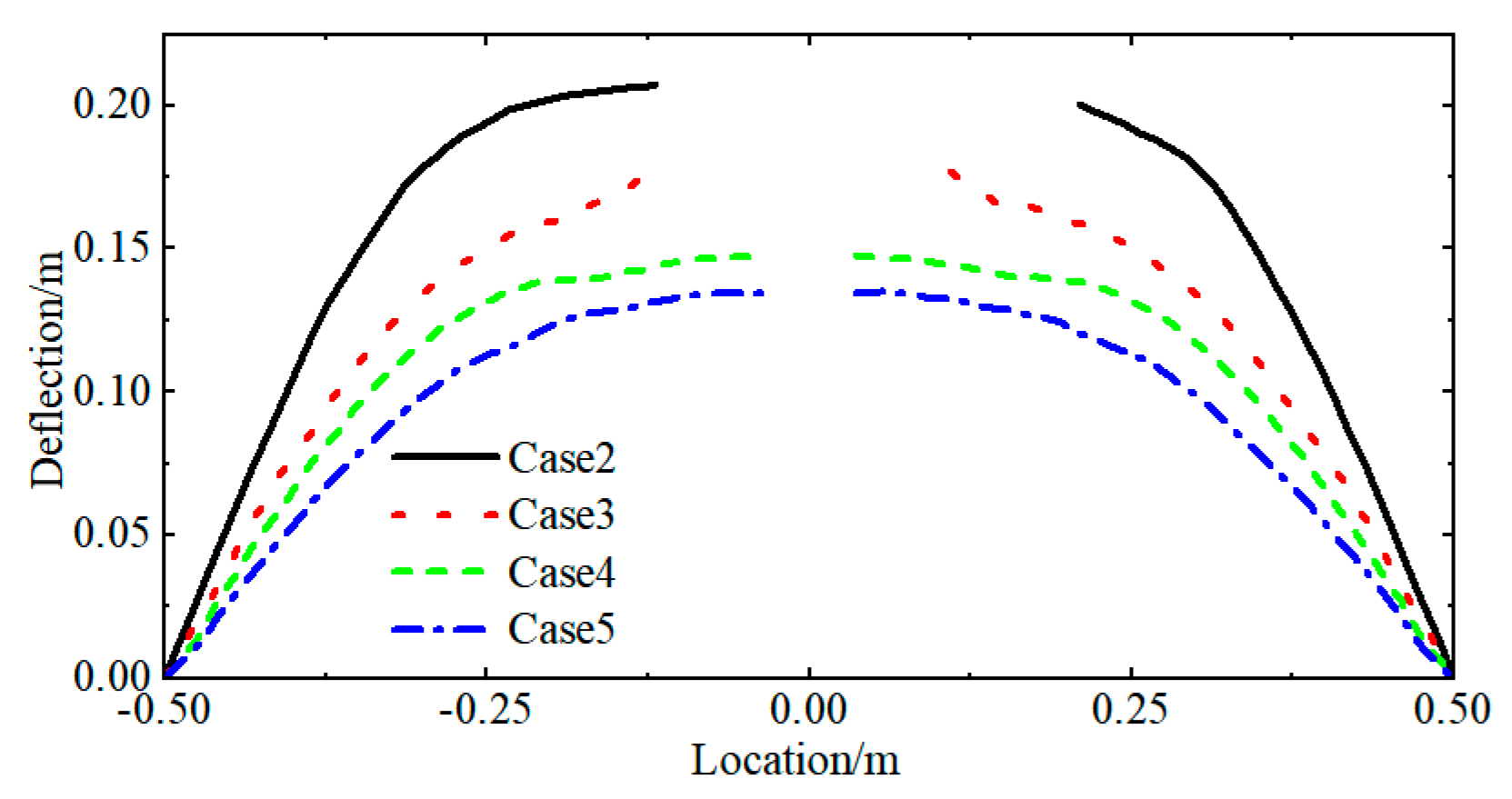
Figure 12 shows the deflection distribution along the central axis of the outer plate at 2.5 ms. It indicates that under the influence of impact loads and bubble pulse loads, upward plastic strain was observed in the outer plate across all cases. The deflection of the outer plate increased as the water level decreased. In cases 2 and 3, petal-shaped breaches appeared even in the central area. This is due to the fact that as the water level decreases, the transfer of impact load and bubble pulsation load to the inner plate through the air medium becomes more challenging. Consequently, the impact load on the outer plate increases, and the water in the compartment dampens the outer plate’s deformation, leading to increased deflection.
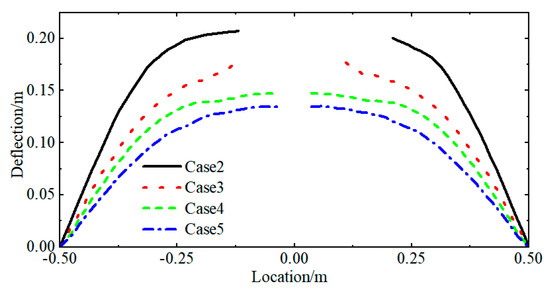
Figure 12.
Deflection distribution of the outer plate under cases 2, 3, 4, and 5.
Table 10 presents a statistical summary of the damage characteristics of the inner and outer plates for the four cases discussed in this section. The area of the breaches in the outer plate excludes prefabricated orifices. Combining the above studies, the effect of the water level within the compartments on the damage characteristics of the double-layer plates can be summarized as follows: As the water level increases, the deformation of the outer plate decreases, while that of the inner plate increases. According to the damage characteristics statistics in Table 10, appropriately setting the water level inside the compartments can enhance the explosion resistance of the double-layer plates. Optimal performance is achieved when the water level is at 0.1 m; at this level, no further breaches occur in the outer plate, and the deformation of the inner plate is minimal. In practical applications, this can help delay the sinking speed of a ship.
Table 10.
The damage characteristics of the inner and outer plates.
3.2.2. Effect of Charge Distance
This section investigates the effects of charge distance on the damage characteristics of the double-layer plates. Based on Case 2, while keeping parameters such as water level constant, Cases 1 and 6 were established in Table 7 with charge distances of 0.15 m and 0.25 m, respectively. Figure 13 shows the numerical simulation results for Case 1.


Figure 13.
Numerical simulation results for Case 1.
As shown in Figure 13a, at t = 0.3 ms, the outer plate rapidly deforms upwards, absorbing the majority of the shockwave load. Comparing this with Figure 7a indicates that a decrease in charge distance significantly increases the deformation of the outer plate. Due to the difficulty of shockwave propagation through air, the inner plate does not exhibit significant plastic strain regions. At t = 0.9 ms, as shown in Figure 13b, the outer plate comes into direct contact with the inner plate under the influence of bubble pulsation loads, leading to the immediate deformation of the latter. At this moment, a noticeable petal-shaped breach appears in the central area of the outer plate. At t = 1.5 ms, as shown in Figure 13c, the bubble expands further and contacts the double-layer plates. Consequently, the pulsating bubble load directly impacts both outer and inner plates, escalating their plastic strain, and the petal-shaped breach in the outer plate also enlarges. As the inner and outer plates are in contact at this moment, the petal-shaped breach does not curl outward. At t = 2.1 ms, as shown in Figure 13d, the expansion of the bubble is slowed due to the constraints of the double-layer plates. Consequently, plastic strain intensifies in the peripheral regions of both inner and outer plates, further enlarging the petal-shaped breach area in the outer plate. At t = 2.5 ms, as shown in Figure 13e, the bubble reaches its maximum expansion, with the petal-shaped breach in the outer plate about to spread to the edges; the entire outer plate is about to be torn apart, while the inner plate undergoes maximum plastic strain by the pulsating bubble load.
Subsequently, a summary of the damage characteristics of the double-layer plates for the three cases discussed in this section is presented. Figure 14 shows the deflection distribution along the central axis of the inner plate at t = 2.5 ms, as well as the time history curve. An analysis of both figures reveals that the damage patterns of the inner plates are essentially identical across the three cases, each exhibiting upward plastic deformation induced by the impact loads of compartment flooding. The deflection of the inner plate in Case 1 is significantly greater than in Cases 2 and 6. This is attributed to the extensive petal-shaped breach at the center of the outer plate in Case 1, resulting from the combined effects of shockwave and bubble pulsation loads. This increases the contact area between the bubble and the inner plate, where the bubble pulsation load directly affects the inner plate. Although Case 2 exhibits greater overall deflection than Case 6, by t = 2.5 ms, the deflections of the two plates are essentially the same. This occurs because, in the late stages of bubble pulsation, the internal pressure of the bubble is much lower than the atmospheric pressure. Under the influence of atmospheric pressure, the central area of the inner plate in Case 2 is crushed, resulting in sinking deformation. In Case 6, due to the larger charge distance, the bubble has not contacted the double-layer plates at t = 2.5 ms. The water inside the compartment provides substantial damping, which minimizes the sinking of the central area of the inner plate in Case 6.

Figure 14.
Deflection of the inner plate in cases 1, 2, and 6. (a) At the final stage (t = 2.5 ms) along the center axis; (b) Time history curve of the deflection at P1.
Figure 15 presents the deflection distribution along the central axis of the outer plate at t = 2.5 ms. The damage characteristics of the outer plates in all three cases are essentially same, with each demonstrating upward plastic deformation resulting from the combined impacts of shock and bubble pulsation loads. Moreover, petal-shaped breaches form in the central area. As the charge distance decreases, both the deflection and the area of the breaches in the outer plate increase.
Figure 15.
Deflection distribution of the outer plate under cases 1, 2, and 6.
Table 11 summarizes the damage characteristics of the inner and outer plates for the three cases discussed in this section. The area of the breaches in the outer plate excludes prefabricated orifices. Combining the above studies reveals that as the charge distance decreases, both the deflection and breach area of the outer plate increase. Similarly, the deflection of the inner plate also increases. The changes in deformation for both layers show a consistent pattern in response to variations in this parameter.
Table 11.
The damage characteristics of the inner and outer plates.
4. Conclusions
This study employed numerical simulations using the CEL model to investigate the damage characteristics of double-layer plates with a perforated outer plate under UNDEX loads. The CEL method was validated with small-scale explosion tests. A series of cases were simulated to analyze the comprehensive damage characteristics of the double-layer plates. The main conclusions are as follows:
- (1)
- The combined shockwave and bubble pulsation loads cause deformation of the outer plate, potentially leading to petal-shaped breaches under severe conditions.
- (2)
- The primary causes of deformation in the inner plate are the driving of the outer plate and the flooding impact loads within the compartment.
- (3)
- The deformation of the outer plate increases as the water level inside the compartment decreases. Petal-shaped breaches emerge when the water level falls below 0.05 m. Conversely, the deformation of the inner plate increases as the water level rises.
- (4)
- The deformation of both the inner and outer plates follows a consistent pattern in response to changes in the charge distance parameter, with deformation increasing as the charge distance decreases.
- (5)
- The double-layer plates demonstrate maximum explosion resistance when the water level within the compartment is 0.1 m.
Author Contributions
Conceptualization, X.H.; methodology, J.-W.M.; software, J.-W.M.; validation, J.-W.M. and X.L.; formal analysis, X.H.; investigation, J.-W.M. and X.L.; resources, X.H. and P.D.; data curation, J.-W.M.; writing—original draft preparation, J.-W.M.; writing—review and editing, X.H., J.-W.M., X.L., P.D. and A.O.; visualization, X.H. and P.D.; supervision, J.-W.M.; project administration, X.H.; funding acquisition, X.H. All authors have read and agreed to the published version of the manuscript.
Funding
This research was funded by the National Natural Science Foundation of China (No. 52101373), the Shenzhen Science and Technology Program (No. JCYJ20230807145621043), the Young Talent Fund of University Association for Science and Technology in Shaanxi (No. 20210417), and the Innovation Capability Support Program of Shaanxi (No. 2024RS-CXTD-15).
Institutional Review Board Statement
Not applicable.
Informed Consent Statement
Not applicable.
Data Availability Statement
There are no publicly available data for this study.
Conflicts of Interest
The authors declare no conflicts of interest.
References
- Zhang, A.; Ming, F.; Liu, Y.; Li, S.; Wang, S. Review of research on underwater explosion related to load characteristics and ship damage and protection. Chin. J. Ship Res. 2023, 18, 139–154, 196. (In Chinese) [Google Scholar]
- Jin, J.; Zhu, X.; Hou, H.; Li, D.; Chen, P.; Gao, S. Review on the damage and protection of large naval warships subjected to underwater contact explosions. Exp. Shock Waves 2020, 40, 111401. (In Chinese) [Google Scholar]
- Gu, Y.; Wang, J.; Li, H.; Tang, K.; Liu, L. Formation characteristics and penetration performance of an underwater shaped charge jet. Ocean Eng. 2022, 258, 111695. [Google Scholar] [CrossRef]
- Zhang, Z.; Wang, C.; Xu, W.; Hu, H. Penetration of annular and general jets into underwater plates. Comput. Part. Mech. 2021, 8, 289–296. [Google Scholar] [CrossRef]
- Zhang, Z.; Wang, C.; Xu, W.; Hu, H.; Guo, Y. Application of a new type of annular shaped charge in penetration into underwater double-hull structure. Int. J. Impact Eng. 2022, 159, 104057. [Google Scholar] [CrossRef]
- Huang, X.; Hu, H.; Li, S.; Zhang, A. Nonlinear dynamics of a cavitation bubble pair near a rigid boundary in a standing ultrasonic wave field. Ultrason. Sonochem. 2020, 64, 104969. [Google Scholar] [CrossRef] [PubMed]
- Wang, Q.; Feng, L.H.; Liu, N.N.; Li, M.; Zhao, P.D.; Zhang, L.; Wang, S.P. Experimental study of load characteristics caused by underwater explosion bubble collapsing in the neighborhood of a rigid wall. Ocean Eng. 2023, 287, 115903. [Google Scholar] [CrossRef]
- Li, S.M.; Zhang, A.M.; Cui, P.; Li, S.; Liu, Y.L. Vertically neutral collapse of a pulsating bubble at the corner of a free surface and a rigid wall. J. Fluid Mech. 2023, 962, A28. [Google Scholar] [CrossRef]
- Xu, Y.F.; Zhang, S.; Cui, P.; Wang, S.P.; Zhang, A.M. Experimental study on the dynamics of a spark bubble near the top of a cylinder and associated annular secondary cavitation bubbles. Phys. Fluids 2023, 35, 123342. [Google Scholar] [CrossRef]
- Cui, J.; Zhou, T.R.; Huang, X.; Li, Z.C. Experimental study of bubble dynamics in the neighbourhood of a vertical incomplete boundary. Ultrason. Sonochem. 2021, 75, 105587. [Google Scholar] [CrossRef]
- Huang, X.; Wang, S.; Liu, Y.; Hu, H. Dynamic interaction of a bubble and discontinuous boundaries: A three-dimensional study with the fast multipole boundary element method. Eng. Anal. Boundary Elem. 2020, 110, 1–15. [Google Scholar] [CrossRef]
- He, M.; Zhang, A.; Liu, Y. Interaction of the underwater explosion bubbles and nearby double-layer structures with circular holes. Exp. Shock Waves 2020, 40, 111402. (In Chinese) [Google Scholar]
- Liu, N.; Wu, W.; Zhang, A.; Liu, Y. Experimental and numerical investigation on bubble dynamics near a free surface and a circular opening of plate. Phys. Fluids 2017, 29, 107102. [Google Scholar] [CrossRef]
- Sun, P.N.; Le Touze, D.; Oger, G.; Zhang, A.M. An accurate SPH Volume Adaptive Scheme for modeling strongly-compressible multiphase flows. Part 1: Numerical scheme and validations with basic 1D and 2D benchmarks. J. Comput. Phys. 2021, 426, 109937. [Google Scholar] [CrossRef]
- Sun, P.N.; Le Touze, D.; Oger, G.; Zhang, A.M. An accurate SPH Volume Adaptive Scheme for modeling strongly-compressible multiphase flows. Part 2: Extension of the scheme to cylindrical coordinates and simulations of 3D axisymmetric problems with experimental validations. J. Comput. Phys. 2021, 426, 109936. [Google Scholar] [CrossRef]
- Yu, Z.; Ni, B.Y.; Wu, Q.; Wang, Z.; Liu, P.; Xue, Y. Numerical Simulation of Icebreaking by Underwater-Explosion Bubbles and Compressed-Gas Bubbles Based on the ALE Method. J. Mar. Sci. Eng. 2024, 12, 58. [Google Scholar] [CrossRef]
- Vannucchi de Camargo, F. Survey on Experimental and Numerical Approaches to Model Underwater Explosions. J. Mar. Sci. Eng. 2019, 7, 15. [Google Scholar] [CrossRef]
- Si, N.; Lu, Z.; Brown, A. Coupling with the Embedded Boundary Method in a Runge-Kutta Discontinuous-Galerkin Direct Ghost-Fluid Method (RKDG-DGFM) Framework for Fluid-Structure Interaction Simulations of Underwater Explosions. J. Mar. Sci. Eng. 2021, 9, 1375. [Google Scholar] [CrossRef]
- Qin, H.; Liu, Y.L.; Tian, Z.L.; Liu, W.T.; Wang, S.P. Numerical investigation of the underwater explosion of a cylindrical explosive with the Eulerian finite-element method. Phys. Fluids 2024, 36, 016104. [Google Scholar] [CrossRef]
- Zhang, W.; Yao, X.; Wang, Y.; Wang, Z. Experimental study and numerical model adequacy assessment of hull structure dynamic response subject to underwater explosion. Ships Offshore Struct. 2020, 15, 1023–1036. [Google Scholar] [CrossRef]
- Liu, Y.Z.; Ren, S.F.; Zhao, P.F. Application of the deep neural network to predict dynamic responses of stiffened plates subjected to near-field underwater explosion. Ocean Eng. 2022, 247, 110537. [Google Scholar] [CrossRef]
- Zhang, N.; Zong, Z.; Zhang, W. Dynamic response of a surface ship structure subjected to an underwater explosion bubble. Mar. Struct. 2014, 35, 26–44. [Google Scholar] [CrossRef]
- Wang, J.X.; Zong, Z.; Liu, K.; Cui, J. Simulations of the dynamics and interaction between a floating structure and a near-field explosion bubble. Appl. Ocean Res. 2018, 78, 50–60. [Google Scholar] [CrossRef]
- Huang, X.; Mao, J.W.; Li, Q.; Wang, Z.; Pan, G.; Hu, H.B. On the interaction between the underwater explosion and the double-layer structure with an orifice on the outer plate. Ocean Eng. 2024, 306, 118050. [Google Scholar] [CrossRef]
- Gan, N.; Liu, L.; Yao, X.; Wang, J.; Wu, W. Experimental and numerical investigation on the dynamic response of a simplified open floating slender structure subjected to underwater explosion bubble. Ocean Eng. 2021, 219, 108308. [Google Scholar] [CrossRef]
- Chen, Y.; Sun, Y.; Wang, C. Damage Characteristics of Ship’s Double Bottom Structure Subjected to Underwater Explosion. Acta Armament. 2023, 44, 670. [Google Scholar]
- Zong, Z.; Zhao, Y.; Li, H. A numerical study of whole ship structural damage resulting from close-in underwater explosion shock. Mar. Struct. 2013, 31, 24–43. [Google Scholar] [CrossRef]
- Simulia, D. ABAQUS 6.11 analysis user’s manual. Abaqus 2011, 6, 22. [Google Scholar]
- Zhang, Z.; Xie, Y.; Wang, C.; Deng, W.; Liao, Q. Coupling mechanism between damaged structure and underwater explosion bubble near free surface. Trans. Beijing Inst. Technol. 2022, 42, 909–917. (In Chinese) [Google Scholar]
- Ramajeyathilagam, K.; Vendhan, C.P. Deformation and rupture of thin rectangular plates subjected to underwater shock. Int. J. Impact Eng. 2004, 30, 699–719. [Google Scholar] [CrossRef]
- Johnson, G.R. A Constitutive Model and Date for Metals Subject to Large Strains, High Strain Rate and High Temperatures. In Proceedings of the 7th International Symposium on Ballistics, Hague, The Netherlands, 19–21 April 1983. [Google Scholar]
- Kong, X. Research on the Blast Loadings and the Response of Multi-layer Protective Structure. Doctor’s Thesis, Wuhan University of Technology, Wuhan, China, 2013. (In Chinese). [Google Scholar]
- Chen, G.; Chen, X.; Chen, Z.; Qu, M. Simulations of A3 steel blunt projectiles impacting 45 steel plates. Exp. Shock Waves 2007, 27, 390–397. (In Chinese) [Google Scholar]


Disclaimer/Publisher’s Note: The statements, opinions and data contained in all publications are solely those of the individual author(s) and contributor(s) and not of MDPI and/or the editor(s). MDPI and/or the editor(s) disclaim responsibility for any injury to people or property resulting from any ideas, methods, instructions or products referred to in the content. |
© 2024 by the authors. Licensee MDPI, Basel, Switzerland. This article is an open access article distributed under the terms and conditions of the Creative Commons Attribution (CC BY) license (https://creativecommons.org/licenses/by/4.0/).