
Status and Challenges of Marine Current Turbines: A Global Review


Abstract
1. Introduction
2. The Technological Aspects of MCTs
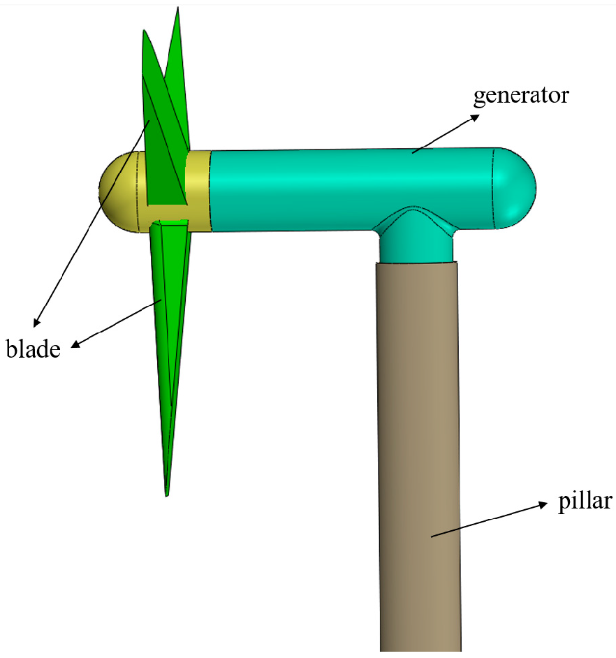
2.1. The Operational Principles and Technical Characteristics of MCTs
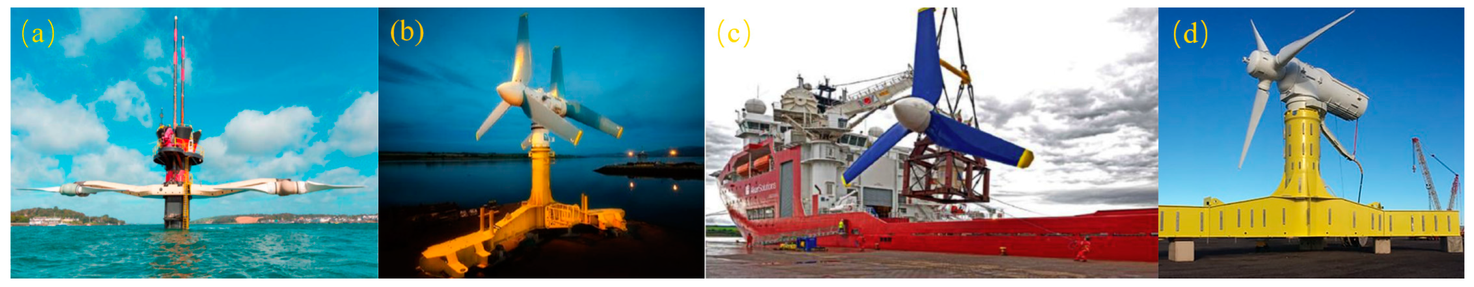
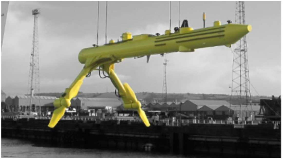
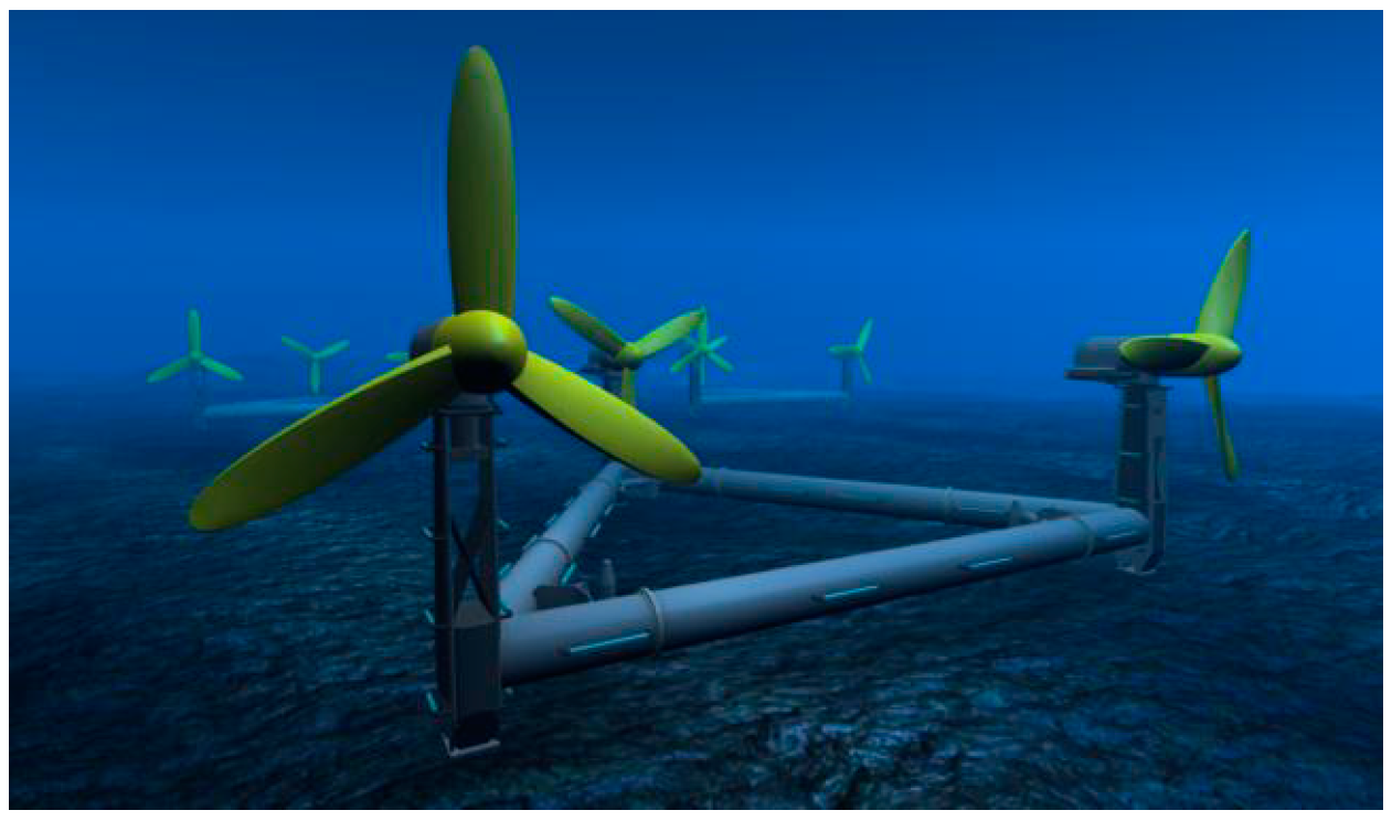
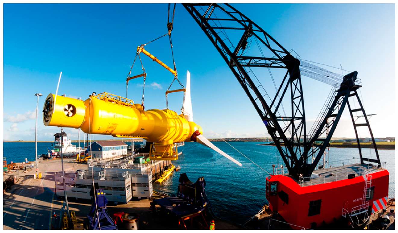
2.2. Developments of Large-Scale MCTs
3. MCT Array Configurations
3.1. Influencing Factors of the MCT Array Configurations
3.1.1. Hydrological Characteristics and Site Selection
3.1.2. Array Layout
3.1.3. Wake Characteristics
3.2. Researches on Array Configurations
3.3. Large MCT Array Projects
- Phase 1A: A gravity support installation method is adopted. Each turbine has a dedicated subsea array cable laid directly on the seabed, and the electric power is fed into the onshore power conversion building.
- Phase 1B: Two additional AR2000 turbines were linked to a single power export cable through the new subsea hub, ultimately connecting to the National Grid via the MeyGen substation [87].
- Phase 2: The MeyGen project is granted a Contract For Difference (CFD) in Allocation Round 4 for 28 MW at an agreed strike price of £178.54 per MWh, with a targeted commissioning date set for 2027.
- Phase 3: MeyGen’s Phase 3 is poised to bring the remaining portion of the consented project to fruition. With the recent allocation of 28 MW in Allocation Round 4 (AR4), MeyGen holds an additional consent for 52 MW, making it eligible for future bidding in upcoming CFD Allocation Rounds.
4. Pre-Commercialization of MCTs
4.1. Policy
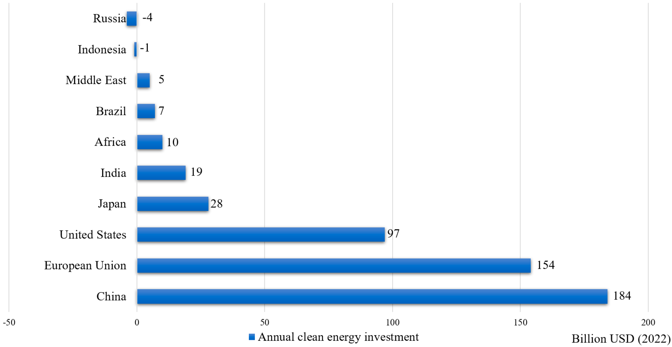
4.2. Investment
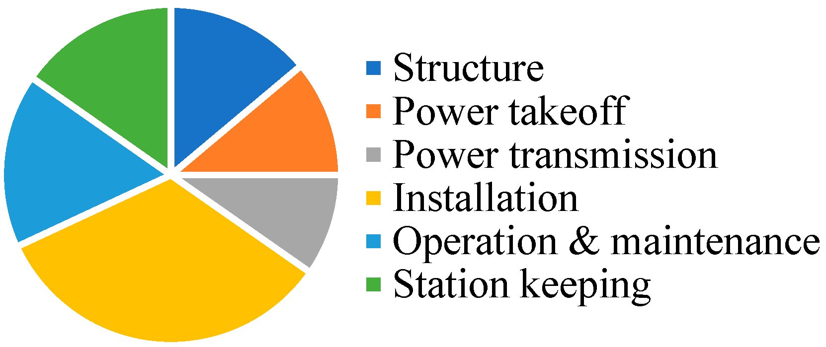
4.3. Economic Cost
5. Challenges
5.1. Technical Aspects
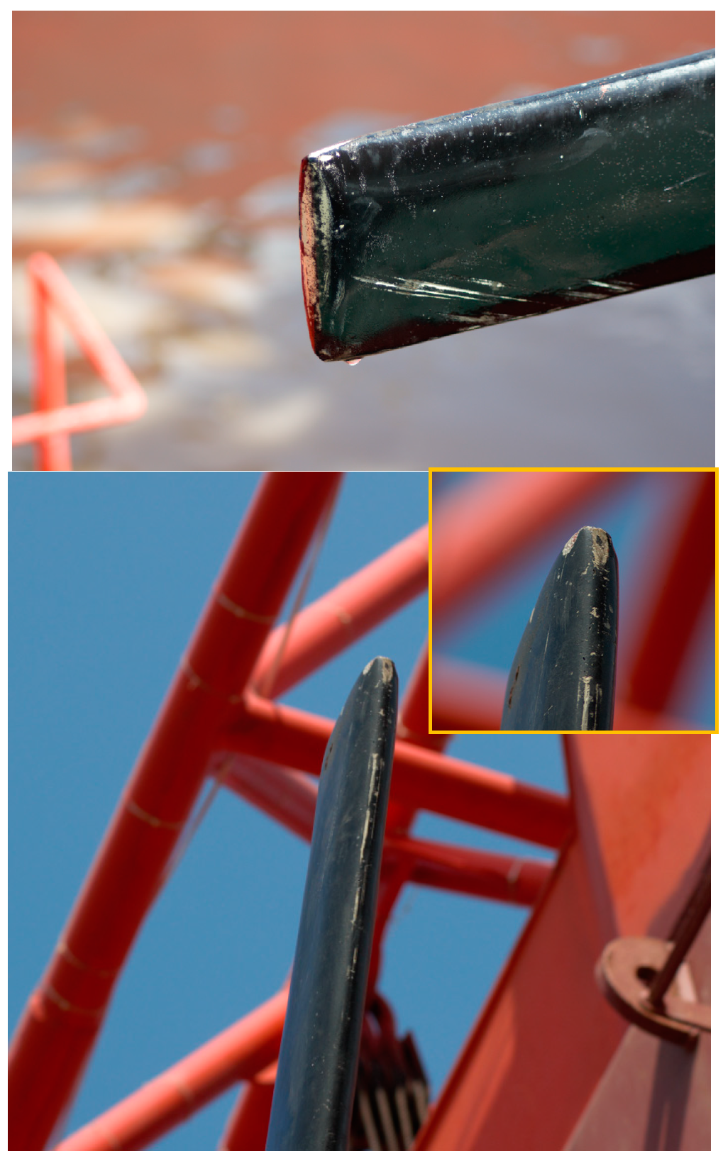
5.1.1. Design of the Blades
5.1.2. Selection of the Transmission System
5.2. Construction of Test Sites
6. Perspective of Application
6.1. Power Supply for an Offshore Island with the Multi-Energy System
6.2. Power Supply for Deep-Sea Marine Instruments and Devices
6.3. Marine Hydrogen Industry
7. Conclusions
Author Contributions
Funding
Institutional Review Board Statement
Informed Consent Statement
Data Availability Statement
Conflicts of Interest
Abbreviations
| Variable | Definitions |
| MCT | marine current turbine |
| EMEC | European Marine Energy Centre |
| LCOE | Levelized Cost of Energy |
| RITE | Roosevelt Island Tidal Energy |
| EnFAIT | Enabling Future Arrays in Tidal |
| PPA | Power Purchase Agreements |
References
- Wang, X.; Lu, Y.; Chen, C.; Yi, X.; Cui, H. Total-Factor Energy Efficiency of Ten Major Global Energy-Consuming Countries. J. Environ. Sci. 2024, 137, 41–52. [Google Scholar] [CrossRef]
- Li, R. The Overview of the Development of Future Energy. Proc. IOP Conf. Ser. Earth Environ. Sci. 2021, 651, 022044. [Google Scholar] [CrossRef]
- Baydyk, T.; Kussul, E.; Wunsch, D.C., II. Renewable energy: Solar, wind, and others. In Intelligent Automation in Renewable Energy. Computational Intelligence Methods and Applications; Springer: Cham, Switzerland, 2019. [Google Scholar]
- Tran, T.T.D.; Smith, A.D. fEvaluation of Renewable Energy Technologies and Their Potential for Technical Integration and Cost-Effective Use within the U.S. Energy Sector. Renew. Sustain. Energy Rev. 2017, 80, 1372–1388. [Google Scholar] [CrossRef]
- Su, W.; Wei, H.; Guo, P.; Hu, Q.; Guo, M.; Zhou, Y.; Zhang, D.; Lei, Z.; Wang, C. Research on Hydraulic Conversion Technology of Small Ocean Current Turbines for Low-Flow Current Energy Generation. Energies 2021, 14, 6499. [Google Scholar] [CrossRef]
- O’Doherty, T.; O’Doherty, D.M.; Mason-Jones, A. Tidal energy technology. In Wave and Tidal Energy; John Wiley & Sons Ltd.: Hoboken, NJ, USA, 2018; pp. 105–150. ISBN 978-1-119-01449-2. [Google Scholar]
- Hanson, H.P.; VanZwieten, J.H.; Alsenas, G.M. Ocean current energy conversion. In Springer Handbook of Ocean Engineering; Springer: Cham, Switzerland, 2016. [Google Scholar]
- Zhou, Z.; Benbouzid, M.; Charpentier, J.F.; Scuiller, F.; Tang, T. Developments in Large Marine Current Turbine Technologies—A Review. Renew. Sustain. Energy Rev. 2017, 71, 852–858. [Google Scholar] [CrossRef]
- Magagna, D.; Uihlein, A. Ocean Energy Development in Europe: Current Status and Future Perspectives. Int. J. Mar. Energy 2015, 11, 84–104. [Google Scholar] [CrossRef]
- Chen, H.; Tang, T.; Ait-Ahmed, N.; Benbouzid, M.E.H.; Machmoum, M.; Zaim, M.E.H. Attraction, Challenge and Current Status of Marine Current Energy. IEEE Access 2018, 6, 12665–12685. [Google Scholar] [CrossRef]
- Esteban, M.; Gasparatos, A.; Doll, C.N.H. Recent developments in ocean energy and offshore wind: Financial challenges and environmental misconceptions. In Sustainability Through Innovation in Product Life Cycle Design; Matsumoto, M., Masui, K., Fukushige, S., Kondoh, S., Eds.; Springer: Singapore, 2017; pp. 735–746. ISBN 978-981-10-0471-1. [Google Scholar]
- Wilberforce, T.; El Hassan, Z.; Durrant, A.; Thompson, J.; Soudan, B.; Olabi, A.G. Overview of Ocean Power Technology. Energy 2019, 175, 165–181. [Google Scholar] [CrossRef]
- Ng, K.-W.; Lam, W.-H.; Ng, K.-C. 2002–2012: 10 Years of Research Progress in Horizontal-Axis Marine Current Turbines. Energies 2013, 6, 1497–1526. [Google Scholar] [CrossRef]
- Zhang, L.; Zhang, S.; Rao, Y.; Zhang, C.; Jiang, K.; Shen, C.; Zhang, K.; Zhao, Z.; Zeng, P. New Floating Table Tidal Power Design. In Proceedings of the Seventh International Conference on Electromechanical Control Technology and Transportation (ICECTT 2022), Guangzhou, China, 27–29 May 2022; SPIE: Bellingham, WA, USA, 2022; Volume 12302, pp. 346–353. [Google Scholar]
- Ruiz-Hussmann, K.; Delafin, P.-L.; Bonamy, C.; Delannoy, Y.; Thévenin, D.; Hoerner, S. A Methodology for the Blade Shape Optimisation of a Vertical Axis Tidal Turbine under Constraints. In Proceedings of the 18th International Conference on Fluid Flow Technologies, Budapest, Hungary, 30 August–2 September 2022. [Google Scholar]
- Chen, J.-H.; Wang, X.-C.; Li, H.; Jiang, C.-H.; Bao, L.-J. Design of the Blade under Low Flow Velocity for Horizontal Axis Tidal Current Turbine. J. Mar. Sci. Eng. 2020, 8, 989. [Google Scholar] [CrossRef]
- Mitchell, S.; Ogbonna, I.; Volkov, K. Aerodynamic Characteristics of a Single Airfoil for Vertical Axis Wind Turbine Blades and Performance Prediction of Wind Turbines. Fluids 2021, 6, 257. [Google Scholar] [CrossRef]
- Tounsi, M.; Beyaoui, M.; Abboudi, K.; Feki, N.; Walha, L.; Haddar, M. Reliability Analysis of Random Aerodynamic Torque of Horizontal Axis Wind Turbine. In Proceedings of the Design and Modeling of Mechanical Systems—III: Proceedings of the 7th Conference on Design and Modeling of Mechanical Systems (CMSM’2017), Hammamet, Tunisia, 27–29 March 2017; Haddar, M., Chaari, F., Benamara, A., Chouchane, M., Karra, C., Aifaoui, N., Eds.; Springer International Publishing: Cham, Switzerland, 2018; pp. 341–348. [Google Scholar]
- Guo, Q.; Zhou, L.J.; Wang, Z.W. Numerical Simulation of Cavitation for a Horizontal Axis Marine Current Turbine. IOP Conf. Ser. Mater. Sci. Eng. 2015, 72, 042045. [Google Scholar] [CrossRef]
- Zhang, J.; Wang, G.; Lin, X. A Review of Recent Development and Key Technology Problems in Utilization of Tidal Stream Energy. J. Hohai Univ. (Nat. Sci.) 2021, 49, 220–232. [Google Scholar]
- Satrio, D.; Utama, I.K.A.P. Experimental Investigation into the Improvement of Self-Starting Capability of Vertical-Axis Tidal Current Turbine. Energy Rep. 2021, 7, 4587–4594. [Google Scholar] [CrossRef]
- Metoyer, R.; Bryant, M.; Granlundt, K.; Mazzoleni, A. Increased Energy Conversion with a Horizontal Axis Turbine in Translation. In Proceedings of the OCEANS 2022, Hampton Roads, VA, USA, 17–22 October 2022; pp. 1–10. [Google Scholar]
- Cullen, J.M.; Allwood, J.M. Theoretical Efficiency Limits for Energy Conversion Devices. Energy 2010, 35, 2059–2069. [Google Scholar] [CrossRef]
- Melikoglu, M. Current Status and Future of Ocean Energy Sources: A Global Review. Ocean Eng. 2018, 148, 563–573. [Google Scholar] [CrossRef]
- Xu, J.; Wang, L.; Yuan, J.; Shi, J.; Wang, Z.; Zhang, B.; Luo, Z.; Tan, A.C.C. A Cost-Effective CNN-BEM Coupling Framework for Design Optimization of Horizontal Axis Tidal Turbine Blades. Energy 2023, 282, 128707. [Google Scholar] [CrossRef]
- Paboeuf, S.; Yen Kai Sun, P.; Macadré, L.-M.; Malgorn, G. Power Performance Assessment of the Tidal Turbine Sabella D10 Following IEC62600-200. In Proceedings of the International Conference on Offshore Mechanics and Arctic Engineering, Busan, Republic of Korea, 18–24 June 2016; American Society of Mechanical Engineers Digital Collection: New York, NY, USA, 2016. [Google Scholar]
- Zhou, Z.; Scuiller, F.; Charpentier, J.F.; Benbouzid, M.; Tang, T. An Up-to-Date Review of Large Marine Tidal Current Turbine Technologies. In Proceedings of the 2014 International Power Electronics and Application Conference and Exposition, Shanghai, China, 5–8 November 2014; pp. 480–484. [Google Scholar]
- Kaddoura, M.; Tivander, J.; Molander, S. Life Cycle Assessment of Electricity Generation from an Array of Subsea Tidal Kite Prototypes. Energies 2020, 13, 456. [Google Scholar] [CrossRef]
- Northern Ireland’s Environment Minister Visits World-Leading SeaGen Tital Turbine. Available online: https://www.siemens.com/uk/en.html (accessed on 27 April 2024).
- MacEnri, J.; Reed, M.; Thiringer, T. Influence of Tidal Parameters on SeaGen Flicker Performance. Philos. Trans. R. Soc. A Math. Phys. Eng. Sci. 2013, 371, 20120247. [Google Scholar] [CrossRef]
- A Global Sustainable Energy Company. Available online: https://saerenewables.com/ (accessed on 26 April 2024).
- World’s Largest Tidal Turbine Will Generate Enough Power for 1000 Homes. Available online: https://newatlas.com/atlantis-ak1000-tidal-turbine-unveiled/16056/ (accessed on 27 April 2024).
- Atlantis Resources Corporation Completes Testing of the AR-1000 Tidal Turbine at Narec—SAE Renewables. Available online: https://saerenewables.com/atlantis-resources-corporation-completes-testing-of-the-ar-1000-tidal-turbine-at-narec/ (accessed on 27 April 2024).
- Faez Hassan, H.; El-Shafie, A.; Karim, O.A. Tidal Current Turbines Glance at the Past and Look into Future Prospects in Malaysia. Renew. Sustain. Energy Rev. 2012, 16, 5707–5717. [Google Scholar] [CrossRef]
- Qian, P.; Feng, B.; Liu, H.; Tian, X.; Si, Y.; Zhang, D. Review on Configuration and Control Methods of Tidal Current Turbines. Renew. Sustain. Energy Rev. 2019, 108, 125–139. [Google Scholar] [CrossRef]
- Palmer, L.; Gillespie, D.; MacAulay, J.D.J.; Sparling, C.E.; Russell, D.J.F.; Hastie, G.D. Harbour Porpoise (Phocoena Phocoena) Presence Is Reduced during Tidal Turbine Operation. Aquat. Conserv. Mar. Freshw. Ecosyst. 2021, 31, 3543–3553. [Google Scholar] [CrossRef]
- Tethys. HS1000 at EMEC. Available online: https://tethys.pnnl.gov/project-sites/hs1000-emec (accessed on 27 April 2024).
- Belloni, C. Hydrodynamics of Ducted and Open-Centre Tidal Turbines. Ph.D. Thesis, Oxford University, Oxford, UK, 2013. [Google Scholar]
- Galloway, G.S.; Catterson, V.M.; Fay, T.; Robb, A.; Love, C. Diagnosis of Tidal Turbine Vibration Data through Deep Neural Networks. In Proceedings of the Third European Conference of the Prognostics and Health Management Society, Bilbao, Spain, 5–8 July 2016; pp. 172–180. [Google Scholar]
- Vimeo. AHH MK1 Tidal Turbine Install 1. MeyGen. Available online: https://vimeo.com/190790140 (accessed on 27 April 2024).
- Magagna, D.; Monfardini, R.; Uihlein, A. JRC Ocean Energy Status Report 2016 Edition; Publications Office of the European Union: Luxembourg, 2016. [Google Scholar]
- Hammerfest, A.H. Renewable Energy from Tidal Currents; Andritz Hydro: Hammerfest, Norway, 2012. [Google Scholar]
- Tethys. ScotRenewables SR2000 at EMEC. Available online: https://tethys.pnnl.gov/project-sites/scotrenewables-sr2000-emec (accessed on 27 April 2024).
- Scotrenewables Tidal Power Kicks Off New Funding Round. Available online: https://www.orbitalmarine.com/news/?start=24 (accessed on 27 April 2024).
- Tokunaga, H.; Waki, I.; Yamaguchi, A.; Akutsu, N.; Matsumoto, K. Growth Condition Dependence of Mg-Doped GaN Film Grown by Horizontal Atmospheric MOCVD System with Three Layered Laminar Flow Gas Injection. J. Cryst. Growth 1998, 189, 519–522. [Google Scholar] [CrossRef]
- Mcevoy, P.; Kim, S. Mooring Load Management for SR2000 Floating Tidal Device Using Non-Linear Polymer Components. In Proceedings of the 12th European Wave and Tidal Energy Conference, Cork, UK, 27 August–1 September 2017. [Google Scholar]
- Nachtane, M.; Tarfaoui, M.; Goda, I.; Rouway, M. A Review on the Technologies, Design Considerations and Numerical Models of Tidal Current Turbines. Renew. Energy 2020, 157, 1274–1288. [Google Scholar] [CrossRef]
- Haverson, D.; Bacon, J.; Smith, H.C.M.; Venugopal, V.; Xiao, Q. Modelling the Hydrodynamic and Morphological Impacts of a Tidal Stream Development in Ramsey Sound. Renew. Energy 2018, 126, 876–887. [Google Scholar] [CrossRef]
- Frost, C.; Evans, P.; Morris, C.; Mason-Jones, A.; O’Doherty, T.; O’Doherty, D. The Effect of Axial Flow Misalignment on Tidal Turbine Performance. In Proceedings of the International Conference on Renewable Energies Offshore, Lisbon, Portugal, 24–26 November 2014. [Google Scholar]
- Frost, C.H.; Evans, P.S.; Harrold, M.J.; Mason-Jones, A.; O’Doherty, T.; O’Doherty, D.M. The Impact of Axial Flow Misalignment on a Tidal Turbine. Renew. Energy 2017, 113, 1333–1344. [Google Scholar] [CrossRef]
- Malinka, C.E.; Gillespie, D.M.; Macaulay, J.D.; Joy, R.; Sparling, C.E. First in Situ Passive Acoustic Monitoring for Marine Mammals during Operation of a Tidal Turbine in Ramsey Sound, Wales. Mar. Ecol. Prog. Ser. 2018, 590, 247–266. [Google Scholar] [CrossRef]
- Warak, P.; Goswami, P. Overview of Generation of Electricity Using Tidal Energy. In Proceedings of the IEEE First International Conference on Smart Technologies for Power, Energy and Control (STPEC 2020), Nagpur, India, 25–26 September 2020. [Google Scholar]
- Rolls-Royce in Talks to Ramp up Tidal Power Deployment. Available online: https://www.renewableenergymagazine.com/ocean_energy/rollsroyce-in-talks-to-ramp-up-tidal (accessed on 27 April 2024).
- Recharge. Rolls-Royce Is Revving up Its Tidal Testing at Emec. Available online: https://www.rechargenews.com/wave-tidal-hydro/rolls-royce-is-revving-up-its-tidal-testing-at-emec/1-1-841453 (accessed on 27 April 2024).
- Rashedi, A.; Khanam, T.; Jeong, B.; Hussain, M. Evaluation of Environmental Sustainability Matrix of Deepgen Tidal Turbine. Ocean Eng. 2022, 266, 113031. [Google Scholar] [CrossRef]
- Winter, A.I. Differences in Fundamental Design Drivers for Wind and Tidal Turbines. In Proceedings of the IEEE OCEANS 2011, Santander, Spain, 6–9 June 2011; pp. 1–10. [Google Scholar]
- Sellar, B.; Harding, S.; Richmond, M. High-Resolution Velocimetry in Energetic Tidal Currents Using a Convergent-Beam Acoustic Doppler Profiler. Meas. Sci. Technol. 2015, 26, 085801. [Google Scholar] [CrossRef]
- Almoghayer, M.A.; Lam, R.; Sellar, B.; Old, C.; Woolf, D.K. Validation of Tidal Turbine Wake Simulations Using an Open Regional-Scale 3D Model against 1MW Machine and Site Measurements. Ocean Eng. 2024, 299, 117402. [Google Scholar] [CrossRef]
- Sabella. Videos. Available online: https://www.sabella.bzh/en/media-center/videos/ (accessed on 27 April 2024).
- Paboeuf, S.; Macadré, L.-M.; Yen Kai Sun, P. A French Application Case of Tidal Turbine Certification; American Society of Mechanical Engineers Digital Collection: New York, NY, USA, 2016. [Google Scholar]
- Fowell, R.; Togneri, M.; Pacheco, A.; Nourrisson, O. Use of an Environmental Proxy to Determine Turbulence Regime Surrounding a Full-Scale Tidal Turbine Deployed within the Fromveur Strait, Brittany, France. Appl. Energy 2022, 326, 119910. [Google Scholar] [CrossRef]
- Arnold, M.; Biskup, F.; Cheng, P.W. Impact of Structural Flexibility on Loads on Tidal Current Turbines. Int. J. Mar. Energy 2016, 15, 100–111. [Google Scholar] [CrossRef]
- Arnold, M.; Biskup, F.; Cheng, P.W. Load Reduction Potential of Variable Speed Control Approaches for Fixed Pitch Tidal Current Turbines. Int. J. Mar. Energy 2016, 15, 175–190. [Google Scholar] [CrossRef]
- Dufour, M.-A.; Pinon, G.; Gaurier, B.; Germain, G.; Facq, J.-V.; Togneri, M.; Represas, F.; Nicolas, E.; Marcille, J. Comparison of the experimental response of two horizontal axis tidal turbines to wave and current from a frequency dependency point of view. In Trends in Renewable Energies Offshore; CRC Press: Boca Raton, FL, USA, 2022; ISBN 978-1-00-336077-3. [Google Scholar]
- Slama, M.; Pinon, G.; El Hadi, C.; Togneri, M.; Gaurier, B.; Germain, G.; Facq, J.-V.; Nuño, J.; Mansilla, P.; Nicolas, E.; et al. Turbine Design Dependency to Turbulence: An Experimental Study of Three Scaled Tidal Turbines. Ocean Eng. 2021, 234, 109035. [Google Scholar] [CrossRef]
- Yeo, E.J.; Kennedy, D.M.; O’Rourke, F. Tidal Current Turbine Blade Optimisation with Improved Blade Element Momentum Theory and a Non-Dominated Sorting Genetic Algorithm. Energy 2022, 250, 123720. [Google Scholar] [CrossRef]
- Prabahar, N.S.S.; Fredriksson, S.T.; Broström, G.; Bergqvist, B. Validation of Actuator Line Modeling and Large Eddy Simulations of Kite-Borne Tidal Stream Turbines against ADCP Observations. Energies 2023, 16, 6040. [Google Scholar] [CrossRef]
- Fredriksson, S.T.; Broström, G.; Bergqvist, B.; Lennblad, J.; Nilsson, H. Modelling Deep Green Tidal Power Plant Using Large Eddy Simulations and the Actuator Line Method. Renew. Energy 2021, 179, 1140–1155. [Google Scholar] [CrossRef]
- Li, Y.; Liu, H.; Lin, Y.; Li, W.; Gu, Y. Design and Test of a 600-kW Horizontal-Axis Tidal Current Turbine. Energy 2019, 182, 177–186. [Google Scholar] [CrossRef]
- Gu, Y.; Liu, H.; Li, W.; Lin, Y.; Li, Y. Integrated Design and Implementation of 120-kW Horizontal-Axis Tidal Current Energy Conversion System. Ocean Eng. 2018, 158, 338–349. [Google Scholar] [CrossRef]
- Jeffcoate, P.; McDowell, J. Performance of PLAT-I, a Floating Tidal Energy Platform for Inshore Applications. In Proceedings of the 12th European Wave and Tidal Energy Conference, Cork, UK, 27 August–1 September 2017. [Google Scholar]
- Frost, C.; Togneri, M.; Jeffcoate, P.; Lake, T.; Boake, C.; Starzmann, R.; Williams, A. A Comparison of Platform and Sea-Bed Mounted Flow Measurement Instrumentation for SME PLAT-I. Int. Mar. Energy J. 2022, 5, 195–200. [Google Scholar] [CrossRef]
- Guerra, M.; Hay, A.E.; Karsten, R.; Trowse, G.; Cheel, R.A. Turbulent Flow Mapping in a High-Flow Tidal Channel Using Mobile Acoustic Doppler Current Profilers. Renew. Energy 2021, 177, 759–772. [Google Scholar] [CrossRef]
- Zhang, J.; Zhang, C.; Angeloudis, A.; Kramer, S.C.; He, R.; Piggott, M.D. Interactions between Tidal Stream Turbine Arrays and Their Hydrodynamic Impact around Zhoushan Island, China. Ocean Eng. 2022, 246, 110431. [Google Scholar] [CrossRef]
- Nago, V.G.; dos Santos, I.F.S.; Gbedjinou, M.J.; Mensah, J.H.R.; Tiago Filho, G.L.; Camacho, R.G.R.; Barros, R.M. A Literature Review on Wake Dissipation Length of Hydrokinetic Turbines as a Guide for Turbine Array Configuration. Ocean Eng. 2022, 259, 111863. [Google Scholar] [CrossRef]
- Fallon, D.; Hartnett, M.; Olbert, A.; Nash, S. The Effects of Array Configuration on the Hydro-Environmental Impacts of Tidal Turbines. Renew. Energy 2014, 64, 10–25. [Google Scholar] [CrossRef]
- Gauvin-Tremblay, O.; Dumas, G. Hydrokinetic Turbine Array Analysis and Optimization Integrating Blockage Effects and Turbine-Wake Interactions. Renew. Energy 2022, 181, 851–869. [Google Scholar] [CrossRef]
- Phoenix, A.; Nash, S. Optimisation of Tidal Turbine Array Layouts Whilst Limiting Their Hydro-Environmental Impact. J. Ocean Eng. Mar. Energy 2019, 5, 251–266. [Google Scholar] [CrossRef]
- Chen, Y.; Lin, B.; Lin, J.; Wang, S. Effects of Stream Turbine Array Configuration on Tidal Current Energy Extraction near an Island. Comput. Geosci. 2015, 77, 20–28. [Google Scholar] [CrossRef]
- Zhang, C.; Zhang, J.; Tong, L.; Guo, Y.; Zhang, P. Investigation of Array Layout of Tidal Stream Turbines on Energy Extraction Efficiency. Ocean Eng. 2020, 196, 106775. [Google Scholar] [CrossRef]
- Dos Santos, I.F.S.; Camacho, R.G.R.; Tiago Filho, G.L. Study of the Wake Characteristics and Turbines Configuration of a Hydrokinetic Farm in an Amazonian River Using Experimental Data and CFD Tools. J. Clean. Prod. 2021, 299, 126881. [Google Scholar] [CrossRef]
- Roc, T.; Greaves, D.; Thyng, K.M.; Conley, D.C. Tidal Turbine Representation in an Ocean Circulation Model: Towards Realistic Applications. Ocean Eng. 2014, 78, 95–111. [Google Scholar] [CrossRef]
- Culley, D.M.; Funke, S.W.; Kramer, S.C.; Piggott, M.D. Integration of Cost Modelling within the Micro-Siting Design Optimisation of Tidal Turbine Arrays. Renew. Energy 2016, 85, 215–227. [Google Scholar] [CrossRef]
- Neill, S.P.; Hashemi, M.R. Fundamentals of Ocean Renewable Energy: Generating Electricity from the Sea; Academic Press: London, UK, 2018; ISBN 978-0-12-810449-1. [Google Scholar]
- Macleod, A.; Watson, A.; Quantrell, D.; Porteous, S.; Wills, T. Tidal Resource, Turbine Wake and Performance Modelling on the EnFAIT Project. In Proceedings of the 13th European Wave and Tidal Energy Conference, Naples, Italy, 1–6 September 2019. [Google Scholar]
- Huchet, M.; Droniou, E.; Perez, L.; Vermeulen, B.; Baldock, A.; Johnson, F.; Boake, C. Wake Characterization of Tidal Turbines in the Pentland Firth Using Vessel-Mounted ADCP Measurements. In Proceedings of the European Wave and Tidal Energy Conference, Bilbao, Spain, 3–7 September 2023; Volume 15. [Google Scholar] [CrossRef]
- Rajgor, G. Tidal Developments Power Forward. Renew. Energy Focus 2016, 17, 147–149. [Google Scholar] [CrossRef]
- Coles, D. Assessment of the Turbulent Flow Upstream of the Meygen Phase 1A Tidal Stream Turbines. In Proceedings of the Asian Wave and Tidal Energy Conference, Taipei, Taiwan, 9–13 September 2018. [Google Scholar]
- Perez, L.; Droniou, E.; Huchet, M.; Johnson, F.; Baldock, A.; Boake, C. Resource Assessment Using a Combination of Seabed Mounted and Semi-Stationary Vessel-Mounted ADCP Measurements. In Proceedings of the European Wave and Tidal Energy Conference, Bilbao, Spain, 3–7 September 2023; Volume 15. [Google Scholar] [CrossRef]
- Xu, T.; Haas, K.A.; Gunawan, B. Estimating Annual Energy Production from Short Tidal Current Records. Renew. Energy 2023, 207, 105–115. [Google Scholar] [CrossRef]
- Murray, R.E.; Simms, A.; Bharath, A.; Beach, R.; Murphy, M.; Kilcher, L.; Scholbrock, A. Toward the Instrumentation and Data Acquisition of a Tidal Turbine in Real Site Conditions. Energies 2023, 16, 1255. [Google Scholar] [CrossRef]
- Li, G.; Zhu, W. Tidal Current Energy Harvesting Technologies: A Review of Current Status and Life Cycle Assessment. Renew. Sustain. Energy Rev. 2023, 179, 113269. [Google Scholar] [CrossRef]
- Nova Innovation. Available online: https://novainnovation.com/ (accessed on 22 May 2024).
- Li, Y.; Li, W.; Liu, H.; Lin, Y.; Gu, Y.; Xie, B. Indirect Load Measurements for Large Floating Horizontal-Axis Tidal Current Turbines. Ocean Eng. 2020, 198, 106945. [Google Scholar] [CrossRef]
- Wang, P.; Zhao, B.; Cheng, H.; Huang, B.; He, W.; Zhang, Q.; Zhu, F. Study on the Performance of a 300W Counter-Rotating Type Horizontal Axis Tidal Turbine. Ocean Eng. 2022, 255, 111446. [Google Scholar] [CrossRef]
- Tsanakas, I.J.A.; Lokhat, I.; Jay, A.; Gregoire, C.; Schnierer, B.; Rusnak, J.; Dvonc, L.; Berthelot, J.; Monet, C.; Garcia, K.; et al. State-of-Play and Emerging Challenges in Photovoltaic Energy Yield Simulations: A Multi-Case Multi-Model Benchmarking Study. Solar RRL 2023, 7, 2200582. [Google Scholar] [CrossRef]
- Glennon, C.; Finnegan, W.; Kaufmann, N.; Meier, P.; Jiang, Y.; Starzmann, R.; Goggins, J. Tidal Stream to Mainstream: Mechanical Testing of Composite Tidal Stream Blades to de-Risk Operational Design Life. J. Ocean Eng. Mar. Energy 2022, 8, 163–182. [Google Scholar] [CrossRef]
- Morales, R.; Segura, E. Tidal and Ocean Current Energy. J. Mar. Sci. Eng. 2023, 11, 683. [Google Scholar] [CrossRef]
- Si, Y.; Liu, X.; Wang, T.; Feng, B.; Qian, P.; Ma, Y.; Zhang, D. State-of-the-Art Review and Future Trends of Development of Tidal Current Energy Converters in China. Renew. Sustain. Energy Rev. 2022, 167, 112720. [Google Scholar] [CrossRef]
- Liu, H.; Bahaj, A.S. Status of Marine Current Energy Conversion in China. Int. Mar. Energy J. 2021, 4, 11–23. [Google Scholar] [CrossRef]
- Kasharjanto, A.; Erwandi; Mintarso, C.S.J.; Suyanto, E.M.; Rahuna, D. Study of Supply Chain Management of Industrial Plan Manufacturing Development of Marine Power Turbine in Indonesia. IOP Conf. Ser. Earth Environ. Sci. 2023, 1166, 012018. [Google Scholar] [CrossRef]
- Giroud, A. World Investment Report 2023: Investing in Sustainable Energy for All. J. Int. Bus Policy 2024, 7, 128–131. [Google Scholar] [CrossRef]
- Wu, Y.; Wu, H.; Kang, H.-S.; Li, H. Layout Optimization of a Tidal Current Turbine Array Based on Quantum Discrete Particle Swarm Algorithm. J. Mar. Sci. Eng. 2023, 11, 1994. [Google Scholar] [CrossRef]
- Beiter, P.; Musial, W.; Smith, A.; Kilcher, L.; Damiani, R.; Maness, M.; Sirnivas, S.; Stehly, T.; Gevorgian, V.; Mooney, M.; et al. A Spatial-Economic Cost-Reduction Pathway Analysis for U.S. Offshore Wind Energy Development from 2015–2030; National Renewable Energy Lab. (NREL): Golden, CO, USA, 2016.
- Kvernmo, A.B. Ship Collisions with Floating Offshore Wind Turbines. Master’s Thesis, Norwegian University of Science and Technology, Trondheim, Norway, 2023. [Google Scholar]
- Segura, E.; Morales, R.; Somolinos, J.A.; López, A. Techno-Economic Challenges of Tidal Energy Conversion Systems: Current Status and Trends. Renew. Sustain. Energy Rev. 2017, 77, 536–550. [Google Scholar] [CrossRef]
- Liu, T.; Halse, K.H.; Leira, B.J.; Jiang, Z. Comparative Study of the Mating Process for a Spar-Type Floating Wind Turbine Using Two Alternative Installation Vessels. Appl. Ocean Res. 2023, 132, 103452. [Google Scholar] [CrossRef]
- Uihlein, A.; Magagna, D. Wave and Tidal Current Energy—A Review of the Current State of Research beyond Technology. Renew. Sustain. Energy Rev. 2016, 58, 1070–1081. [Google Scholar] [CrossRef]
- Sabella. Recovery of D10 Tidal Turbine. Available online: https://www.sabella.bzh/en/news/recovery-d10-tidal-turbine (accessed on 15 November 2019).
- Cox, K.; Echtermeyer, A. Structural Design and Analysis of a 10MW Wind Turbine Blade. Energy Procedia 2012, 24, 194–201. [Google Scholar] [CrossRef]
- Li, W.; Zhou, H.; Liu, H.; Lin, Y.; Xu, Q. Review on the Blade Design Technologies of Tidal Current Turbine. Renew. Sustain. Energy Rev. 2016, 63, 414–422. [Google Scholar] [CrossRef]
- Keegan, M.H.; Nash, D.H.; Stack, M.M. On Erosion Issues Associated with the Leading Edge of Wind Turbine Blades. J. Phys. D Appl. Phys. 2013, 46, 383001. [Google Scholar] [CrossRef]
- Liu, H.; Gu, Y.; Lin, Y.-G.; Li, Y.-J.; Li, W.; Zhou, H. Improved Blade Design for Tidal Current Turbines. Energies 2020, 13, 2642. [Google Scholar] [CrossRef]
- Musabikha, S.; Utama, I.K.A.P.; Mukhtasor, M. State of the Art in Protection of Erosion-Corrosion on Vertical Axis Tidal Current Turbine. AIP Conf. Proc. 2018, 1964, 020047. [Google Scholar]
- Uşar, D.; Bal, Ş. Cavitation Simulation on Horizontal Axis Marine Current Turbines. Renew. Energy 2015, 80, 15–25. [Google Scholar] [CrossRef]
- Bahaj, A.S.; Molland, A.F.; Chaplin, J.R.; Batten, W.M.J. Power and Thrust Measurements of Marine Current Turbines under Various Hydrodynamic Flow Conditions in a Cavitation Tunnel and a Towing Tank. Renew. Energy 2007, 32, 407–426. [Google Scholar] [CrossRef]
- Liu, H.; Lin, Y.; Shi, M.; Li, W.; Gu, H.; Xu, Q.; Tu, L. A Novel Hydraulic-Mechanical Hybrid Transmission in Tidal Current Turbines. Renew. Energy 2015, 81, 31–42. [Google Scholar] [CrossRef]
- Jelaska, D.; Podrug, S.; Perkušić, M. A Novel Hybrid Transmission for Variable Speed Wind Turbines. Renew. Energy 2015, 83, 78–84. [Google Scholar] [CrossRef]
- Feng, Y.; Qiu, Y.; Crabtree, C.J.; Long, H.; Tavner, P.J. Monitoring Wind Turbine Gearboxes. Wind Energy 2013, 16, 728–740. [Google Scholar] [CrossRef]
- Pinar Pérez, J.M.; García Márquez, F.P.; Tobias, A.; Papaelias, M. Wind Turbine Reliability Analysis. Renew. Sustain. Energy Rev. 2013, 23, 463–472. [Google Scholar] [CrossRef]
- Cheng, M.; Zhu, Y. The State of the Art of Wind Energy Conversion Systems and Technologies: A Review. Energy Convers. Manag. 2014, 88, 332–347. [Google Scholar] [CrossRef]
- Luo, X.; Wang, J.; Dooner, M.; Clarke, J. Overview of Current Development in Electrical Energy Storage Technologies and the Application Potential in Power System Operation. Appl. Energy 2015, 137, 511–536. [Google Scholar] [CrossRef]
- Rajashekara, K.; Krishnamoorthy, H.S.; Naik, B.S. Electrification of Subsea Systems: Requirements and Challenges in Power Distribution and Conversion. CPSS Trans. Power Electron. Appl. 2017, 2, 259–266. [Google Scholar] [CrossRef]
- Myers, L.; Bahaj, A.S. Simulated Electrical Power Potential Harnessed by Marine Current Turbine Arrays in the Alderney Race. Renew. Energy 2005, 30, 1713–1731. [Google Scholar] [CrossRef]
- Chikaura, H.; Oka, Y.; Nakashima, Y.; Nakanishi, Y. Development of a New Type of Seal System for Use in Ocean Current or Tidal Power Generation. In Proceedings of the 2014 16th International Power Electronics and Motion Control Conference and Exposition, Antalya, Turkey, 21–24 September 2014; pp. 828–832. [Google Scholar]
- Gu, Y.; Lin, Y.; Xu, Q.; Liu, H.; Li, W. Blade-Pitch System for Tidal Current Turbines with Reduced Variation Pitch Control Strategy Based on Tidal Current Velocity Preview. Renew. Energy 2018, 115, 149–158. [Google Scholar] [CrossRef]
- Li, Z. Development status, trend and the problems of mechanics of tidal current energy. Chin. J. Theor. Appl. Mech. 2016, 48, 1019–1032. [Google Scholar] [CrossRef]
- Norris, J.; Bryden, I. European Marine Energy Centre: Facilities and Resources. Energy 2007, 160, 51–58. [Google Scholar] [CrossRef]
- Mueller, M.; Jeffrey, H.; Wallace, R.; Von Jouanne, A. Centers for Marine Renewable Energy in Europe and North America. Oceanography 2010, 23, 42–52. [Google Scholar] [CrossRef]
- Whiting, J. Uldolmok Tidal Power Station. Available online: https://tethys.pnnl.gov/project-sites/uldolmok-tidal-power-station (accessed on 26 April 2024).
- Gunawan, B.; Neary, V.S.; Colby, J. Tidal Energy Site Resource Assessment in the East River Tidal Strait, near Roosevelt Island, New York, New York. Renew. Energy 2014, 71, 509–517. [Google Scholar] [CrossRef]
- Chawdhary, S.; Angelidis, D.; Colby, J.; Corren, D.; Shen, L.; Sotiropoulos, F. Multiresolution Large-Eddy Simulation of an Array of Hydrokinetic Turbines in a Field-Scale River: The Roosevelt Island Tidal Energy Project in New York City. Water Resour. Res. 2018, 54, 10188–10204. [Google Scholar] [CrossRef]
- Jo, C.H.; Hwang, S.J. Review on Tidal Energy Technologies and Research Subjects. China Ocean Eng. 2020, 34, 137–150. [Google Scholar] [CrossRef]
- Colby, J.A.; Corren, D.R.; Hernandez, A.A. Advancement of a Tidal Energy Converter Mount Through Integrated Design Process and Risk Management. In Proceedings of the Offshore Technology Conference, Houston, TX, USA, 6–9 May 2019. [Google Scholar]
- Chen, H.; Li, Q.; Benbouzid, M.; Han, J.; Aït-Ahmed, N. Development and Research Status of Tidal Current Power Generation Systems in China. J. Mar. Sci. Eng. 2021, 9, 1286. [Google Scholar] [CrossRef]
- Lin, J.-H.; Wu, Y.-K.; Lin, H.-J. Successful Experience of Renewable Energy Development in Several Offshore Islands. Energy Procedia 2016, 100, 8–13. [Google Scholar] [CrossRef]
- Friedrich, D.; Lavidas, G. Combining offshore and onshore renewables with energy storage and diesel generators in a stand-alone hybrid energy system. In Offshore Energy & Storage 2015; The University of Edinburgh: Edinburgh, UK, 2015. [Google Scholar]
- Kuang, Y.; Zhang, Y.; Zhou, B.; Li, C.; Cao, Y.; Li, L.; Zeng, L. A Review of Renewable Energy Utilization in Islands. Renew. Sustain. Energy Rev. 2016, 59, 504–513. [Google Scholar] [CrossRef]
- Asghari, E.; Abdullah, M.I.; Foroughi, F.; Lamb, J.J.; Pollet, B.G. Advances, Opportunities, and Challenges of Hydrogen and Oxygen Production from Seawater Electrolysis: An Electrocatalysis Perspective. Curr. Opin. Electrochem. 2022, 31, 100879. [Google Scholar] [CrossRef]
- Hassan, Q.; Sameen, A.Z.; Olapade, O.; Alghoul, M.; Salman, H.M.; Jaszczur, M. Hydrogen Fuel as an Important Element of the Energy Storage Needs for Future Smart Cities. Int. J. Hydrogen Energy 2023, 48, 30247–30262. [Google Scholar] [CrossRef]
- Gondal, I.A. Offshore Renewable Energy Resources and Their Potential in a Green Hydrogen Supply Chain through Power-to-Gas. Sustain. Energy Fuels 2019, 3, 1468–1489. [Google Scholar] [CrossRef]
- Nathan, S. Research Trio Awarded Nobel Prize. Engineer 2018, 297, 16. [Google Scholar] [CrossRef]
- Liu, H.; Ren, H.; Gu, Y.; Lin, Y.; Hu, W.; Song, J.; Yang, J.; Zhu, Z.; Li, W. Design and On-Site Implementation of an off-Grid Marine Current Powered Hydrogen Production System. Appl. Energy 2023, 330, 120374. [Google Scholar] [CrossRef]


| Characteristics | Horizontal-Axis MCTs | Vertical-Axis MCTs |
|---|---|---|
| Blade structure | The blade structure is intricate [16]. | The blades feature a symmetrical airfoil structure [17]. |
| Force balance | They generate torque, necessitating a complex support structure to withstand the torsional forces [18]. | They generate rotational torque, producing a relatively straightforward support structure [19]. |
| Startup procedure | They exhibit a substantial self-starting torque, ensuring stable rotation [20]. | They have a limited self-starting capability, leading to significant torque fluctuations [21]. |
| Efficiency | They possess a high energy conversion efficiency [22]. | They have a moderate energy conversion efficiency [23]. |
| Installation and maintenance | Installation and maintenance are relatively complex, demanding more human resources and resources [24,25]. | Installation and maintenance are comparatively straightforward, resulting in lower costs. |
| Turbine Name | Company | Location | Rotor Diameter | Rated Power | Installation Form | Status |
|---|---|---|---|---|---|---|
| SeaGen | Marine Current Turbines (acquired by SAE), UK | Strangford Narrows, Northern Ireland | 16 m/each | 2 × 600 kW at a current velocity of 2.4 m/s | Seabed bottom-supported (liftable) | Installed in 2008 and generated over 9.2 GWh (up to November 2013). Removed in 2017. |
| AK1000 | SIMEC Atlantis Energy (the predecessor is Atlantis Resources), global | EMEC, Orkney, Scotland | 18 m (two rotors) | 1.0 MW | Seabed bottom-supported, piled | Deployed in 2010. Withdrawn soon after one month due to blade failure. |
| AR1000 | As above | 18 m | 1.0 MW at a current velocity of 2.65 m/s | As above | Tested in 2011. Successful open ocean testing for four months. | |
| AR1500 | Globally commercial use | 18 m | 1.5 MW at a current velocity of 3 m/s | As above | 4000 operational hours in Scotland. | |
| SeaGen U | - | 20 m | 1.5 MW | As above | No data. | |
| AR2000 | - | 20 m | 2.0 MW at a current velocity of 3.05 m/s | As above | Currently in development. | |
| AR500 | Naru-Seto, Japan | 11 m | 500 kW | As above | Installed in 2021 and generated about 80,000 kWh in three months. | |
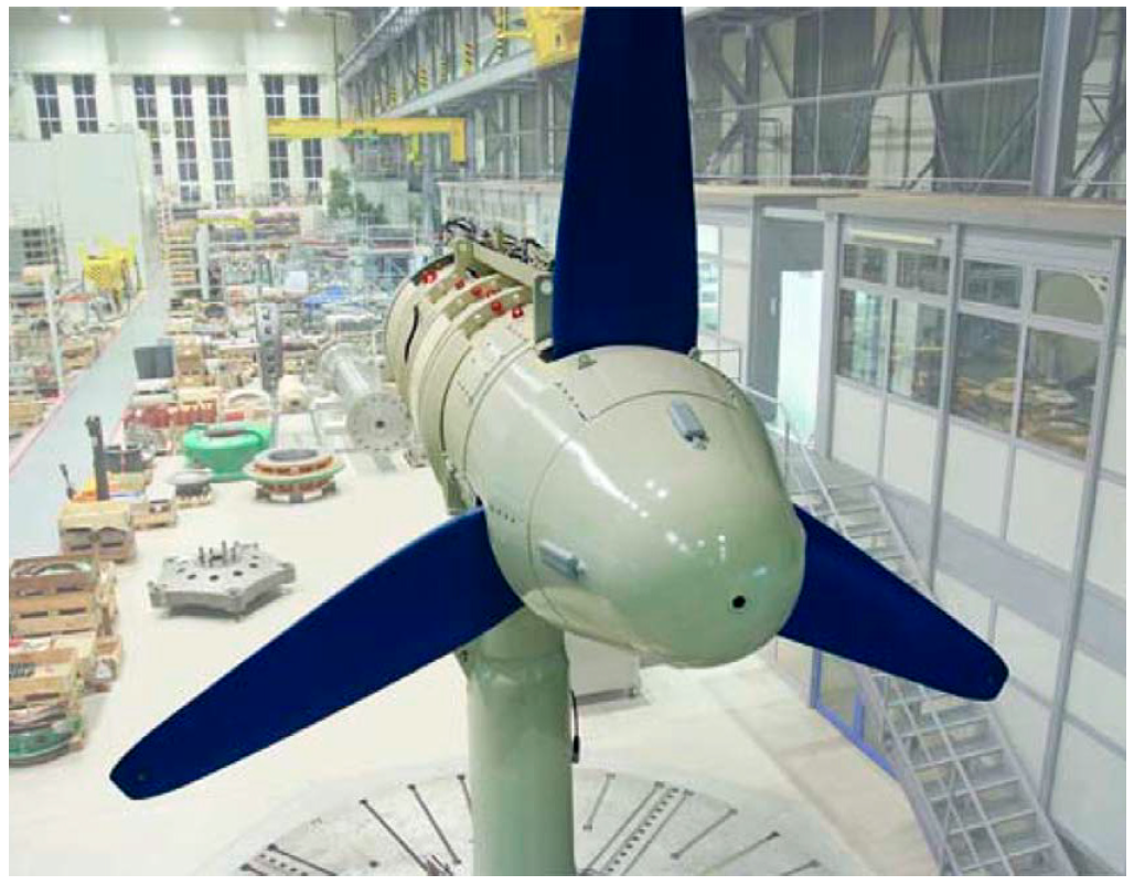
| HS1000 | Andritz Hydro Hammerfest, UK DP Energy, Irish. | Falls of Warness, Orkney, UK | 21 m | 1.0 MW at a water speed of 2.7 m/s | Seabed-mounted by ballast weights or pinning | Installed in 2011. Minor repairs after over 1 year’s operation, more than 1.2 GWh up to 2014. Retrieved in 2015 [8]. |
| MK1 | Pentland Firth, Scotland | 26 m | 1.5 MW | As above | Installed in 2016. | |
| MK1 (new) | Nova Scotia, Canada | 18 m | 1.5 MW | Seabed bottom-supported, piled | Declared to be commissioned in 2023. | |
| SR2000 | Orbital Marine Power (the predecessor is Scotrenewables), Scotland | Kirkwall, Orkney, Scotland | 16 m/each | 2 × 1 MW at a current speed of 3 m/s | Fixed to retractable legs mounted to a floating platform | Installed in 2016. Retrieved in 2018. Produced over 3 GWh. |
| Orbital O2 | - | 20 m/each | 2 × 1 MW at a current speed of 2.5 m/s | As above | The optimized version of SR2000 is in the production stage. | |
| DeltaStream | Tidal Energy, UK | Ramsey Sound, Wales | 15 m | 400 kW at a current speed of 2.25 m/s | Fixed to a triangular frame pinned to the seabed | Deployed late in 2015. Stopped three months later due to faulty equipment. |
| Deepgen-III | Tidal Generation (acquired by Alstom) Alstom (acquired by GE) | Fall of Warness, Eday | No data | 500 kW | Tripod support structure attached to the seabed | Deployed in 2010 and generated over 250 MWh (up to November 2012) [10]. |
| Deepgen-IV | EMEC, Orkney, Scotland | 18 m | 1.0 MW at a current speed of 2.7 m/s | As above | Installed in 2013, generating over 1 GWh (up to November 2014). Extensive test of 18 months period [26,27]. | |
| Sabella D10 | Sabella, France | Fromveur Passage, Ushant Island, France | 10 m | 1.0 MW (maximum) | Separable installation on a gravity-based foundation | Installed in 2015. Retrieved in 2019 for the cooling system’s defect. |
| Sabella D10 (new) | Fromveur Passage, Ushant Island, France | 10 m | 1 MW | Separable installation on a gravity-based foundation | Installed in 2022. Currently on test. | |
| HyTide 1000 | Voith Hydro (Voith Group’s subsidiary company) | EMEC, Orkney, Scotland | 13 m | 1.0 MW at the flow speed of 2.9 m/s | Mounted onto a monopole drilled into the seabed | Installed in 2013. Removed in 2015. |
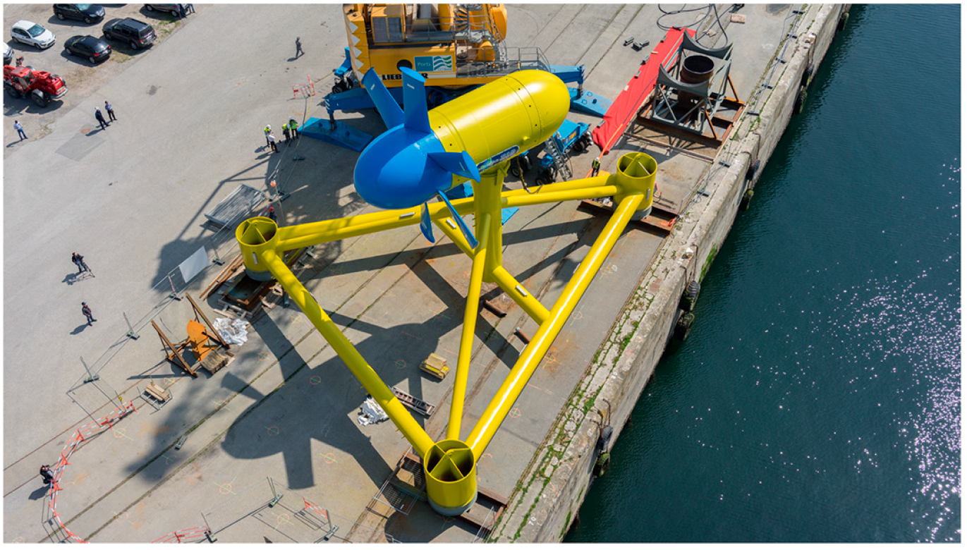
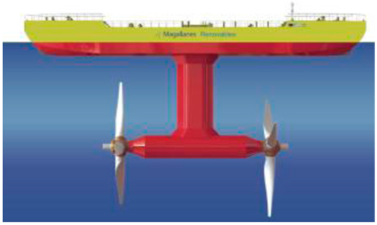
| ATIR | Magallanes Renovables, Spain | EMEC, Orkney, Scotland | 19 m (two rotors) | 2.0 MW | Fixed to the underwater tower of a floating platform | Installed in 2019. Currently on test. |
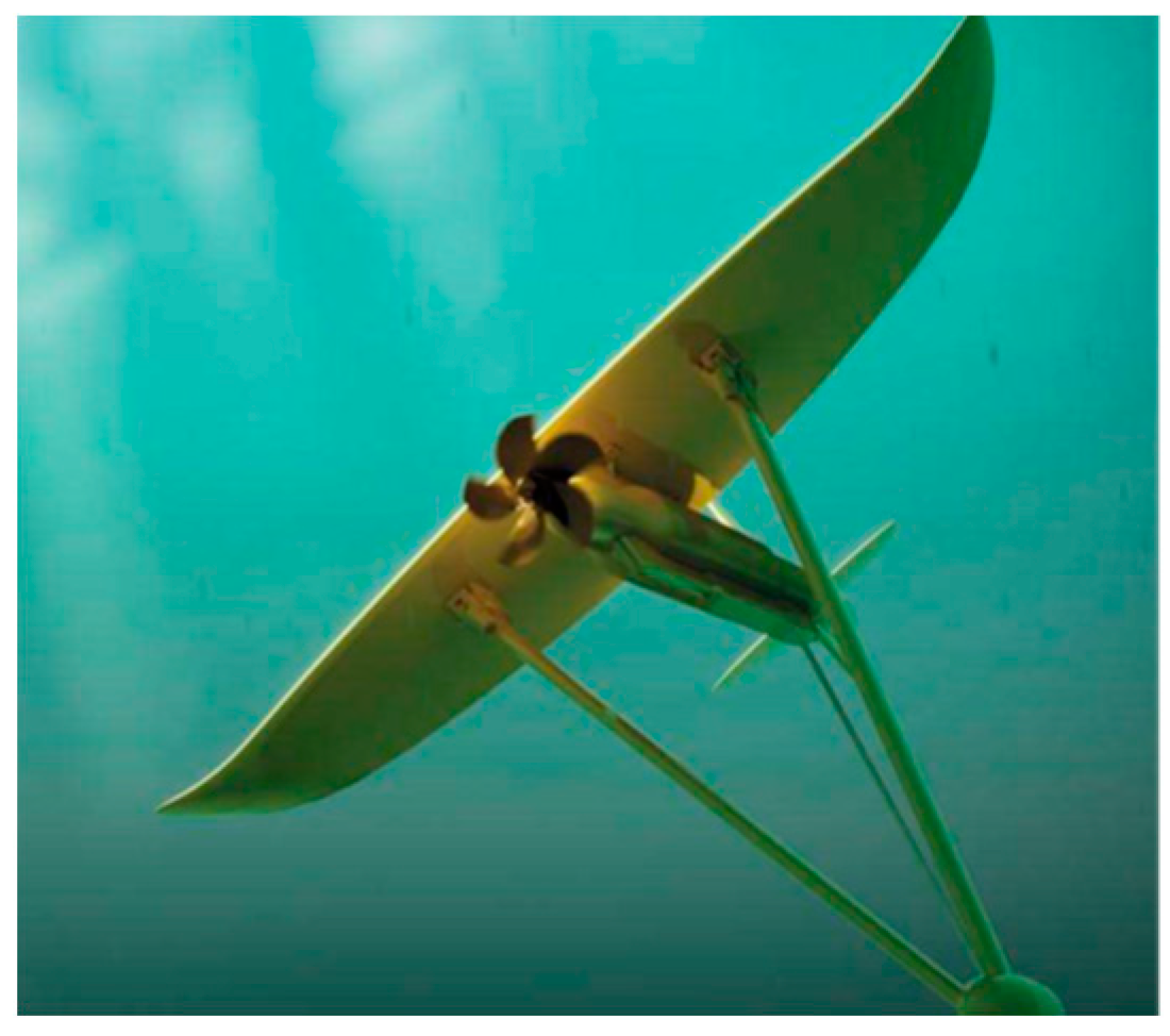
| DG500 | Minesto, Sweden | Holyhead Deep, west of Anglesey, North Wales | 1.5 m | 500 kW | Fixed to a subsea kite attached to the tether, which is connected to a bottom joint | Deployed in 2018 [28]. Currently on test. |
| DRAGON12 | Vestmanna Sound, Faroe Islands | 3.5 m | 1.2 MW | A subsea kite system | Declared to be commissioned in 2023. | |
| ZJU600 | Zhejiang University, China | Zhairuoshan Island, Zhoushan China | 15.45 m | 650 kW at a current speed of 2.5 m/s | Installed on a liftable support structure of a floating platform | Installed and tested in 2017. Successful sea trials for 4 months. |
| GD300 | Guo Dian United Power, China | As above | 17.7 m | 300 kW at a current speed of 1.9 m/s | As above | Installed in 2018. Removed in 2019. Produced about 0.5 GWh. |
| JH300 | Hangzhou Jianghe Hydro-Electric Science & Technology, China | As above | 16.5 m | 300 kW at a current speed of 2 m/s | As above | Installed in 2019. Currently on test. |
| PLAT-I | Sustainable Marine Energy, UK | Nova Scotia, Canada | 6.4 m | 9 MW | Fixed to retractable legs mounted to a floating platform | Installed in 2019. Deployed in 2022. Currently on test. |
| Array Project | Location | Capacity Planned | Turbine Type | Status |
|---|---|---|---|---|
| MeyGen | An offshore site between Scotland’s northernmost coast and the island of Stroma, UK | 398 MW | MK1, AR1500 (Phase 1A) | Split into several phases: Phase 1A (total 6 MW, 4 units) [48]. Phase 1B (total 10 MW, 6 units). Phase 1C (will achieve 73.5 MW, 49 units). Phase 2 (will achieve 101.5 MW in 2027). Phase 3 (will achieve 146 MW in 2028). Phase 4 (will achieve 398 MW) Project construction commenced in January 2015. Turbine installation commenced in October 2016. Phase 1A began operations in April 2018. Phase 1B is in deployment. Until March 2023, it has generated to the grid for 6 years and generated 51 GWh of power. |
| Roosevelt Island Tidal Energy (RITE) | East Channel of the East River, New York Harbor, US | 1 MW | Gen4, Gen5 | Six Gen4 turbines, each 35 kW, were deployed in 2006. The Gen5 commercial class systems were installed and commissioned in 2020. Verdant worked with the European Marine Centre to conduct an off-site power performance assessment using international technical specifications. In 2021, Verdant Power’s RITE project delivered over 312 MWh. |
| OpenHydro turbine | EMEC(UK), France, and Nova Scotia (Canada) | 14 MW | OpenHydro turbine | In 2008, a 250 kW turbine was installed and tested at EMEC. In 2011, a 500 kW turbine was installed at a depth of 35 m. In 2016, two turbines of 2 MW were installed at FORCE in Nova Scotia, Canada. |
| Enabling Future Arrays in Tidal (EnFAIT) | Bluemull Sound, Shetland, UK | 600 kW | Nova Innovation M100 | Three M100 turbines of 100 kW each were deployed from March 2016 to February 2017 [85]. The next phase involved installing an additional three turbines. The fourth marine turbine was installed in 2020, and the fifth and sixth marine turbines were added to the array in 2022. Up to now, EnFAIT has a 30% reduction in the cost of marine power and 95% turbine availability (exceeding the 80% target). |
| ZJU Marine Energy | Zhairuoshan Island, Zhoushan, China | 2 MW | ZJU MCTs | They were commenced in 2014. Until now, three turbines of 60 kW, 120 kW, and 600 kW with floating platforms have been deployed. The 600 kW marine turbine was installed in 2014. The 120 kW marine turbine was installed in 2015. The 650 kW marine turbine was installed in 2017. |
| LHD-tech | Xiushan Island, Zhoushan, China | 3.3 MW | LHD | This project began in 2016. By 2018, it had installed two 200 kW units, three 300 kW units, and one 400 kW unit. By 2022, an additional 1.6 MW unit was added. |
| Countries | Relevant Policies | Impacts |
|---|---|---|
| Norway | ① Power Purchase Agreements (PPA) supporting offshore turbine projects (in 2018). ② Provide tax incentives for renewable energy projects (in 2021). ③ The green electricity certificate system (in 2011). ④ Supporting research and technological innovation. ⑤ Environmental standards. | ① Providing stable electricity prices and market access for projects, and reducing investment risks and attracting investors. ② Contributing to enhancing the economic attractiveness of the project and reducing costs. ③ Enhancing the project’s market competitiveness and aid in reducing carbon emissions, aligning with Norway’s sustainable development goals. ④ Aiding in improving efficiency, reducing costs, and enhancing the competitiveness of the technology. ⑤ Contributing to reducing adverse impacts on the ecosystem and enhancing the project’s sustainability. |
| UK | ① PPA (in 2019). ② Provide a range of financial support, including subsidies, investments, and research and development funding” (in 2022, 68 million pounds sterling). ③ Green Finance Policies (in 2019). ④ Implemented a series of environmental regulations (in 2019). ⑤ Promoting technological innovation. ⑥The Contract for difference scheme (in 2023). | ① Ensuring the sale of project electricity and a stable income. ② Assisting the project in securing startup funding in the early stages and reducing costs. ③ Providing low-interest loans and financial incentives to encourage investors and financial institutions to support these projects. ④ Contributing to reducing the potential impact of projects on the marine ecosystem. ⑤ By supporting research and development projects, enhance efficiency and reliability, thereby reducing costs. |
| France | ① Enacted clean energy and renewable energy policies (in 2018). ② PPA (in 2018). ③ Supporting technological innovation. ④ Implemented a series of environmental regulations (in 2020). | ① Increasing the share of renewable energy in the national energy supply, providing policy support for offshore turbine projects to drive their commercialization. ② Reducing the commercial risks of the project, attracting a significant number of investors and developers. ③ Enhancing the efficiency and reliability of the turbines, reducing costs. ④ Ensuring that projects adhere to high environmental standards, contributing to the reduction of potential impacts on the marine ecosystem. |
| China | ① OESF fund(in May 2010,more than USD 200 million). ② The National Key Research and Development Program of “Research and development of innovative technologies for efficient utilization of ocean energy based on the resource characteristics(in 2019, about USD 2.76 million). ③ The 13-th Five-Year Plan of China (in 2016). ④ The 14-th Five-Year Plan of China (in 2021). | ① Marine current and wave energies secure more than half of the investment amount. ② Several national marine current energy test sites are under construction. ③ Actively developing coastal marine energy resources. ④ Continuing to carry out marine energy demonstration projects and actively promoting the application of megawatt-scale marine energy generators. |
| Japan | ① EIA Act(in 2024). ② Financial Incentives and Subsidies (in 2022). ③ Electricity Business Act. ④ Support for innovation and R&D. | ① Protecting marine ecosystem. ② Contributing to renewable energy capacity and helping reduce reliance on fossil fuels. ③ Helping manage the intermittent nature of renewable energy, ensuring a stable and reliable power supply. ④ Helping lower the costs and improving the feasibility of tidal energy projects. |
| Time | Countries | Investment Amount |
|---|---|---|
| 2010–2019 | France | 69 million euros |
| in 2019 | China | 2.76 million US dollars |
| in 2019 | UK | 35 million US dollars |
| in 2020 | USA | 148 million US dollars |
| in 2020 | China | 150 million US dollars |
| in 2021 | UK | 5.18 million US dollars |
| in 2023 | USA | 35 million US dollars |
| in 2023 | UK | 10 million pounds |
| Transmission System | Advantages | Disadvantages | Examples |
|---|---|---|---|
| Gearbox transmission | ① The conversion of marine energy into electrical energy is highly efficient. ② The technology is relatively mature and has found widespread commercial applications. ③ Suitable for various water flow speeds. ④ Variable speed transmission can be achieved through a multi-stage gearbox. | ① Gearboxes require regular maintenance, which can lead to downtime. ② Gearboxes are susceptible to corrosion from seawater and particle damage. ③ Gearbox transmissions are typically larger, requiring more space. | ZJU Marine Energy SR 2000 |
| Hydraulic transmission | ① Suitable for high-pressure and high-torque applications, efficiently converting marine energy. ② Suitable for various water flow speeds. ③ Relatively compact mechanical structure, saving space. | ① Hydraulic systems are complex and require regular maintenance. ② Hydraulic systems require a high-pressure hydraulic system, which adds complexity. ③ Due to the strong corrosiveness of seawater, special protective measures are needed. | Pulse 100 Deep Green |
| Direct drive transmission | ① Simplified mechanical structure, reducing maintenance requirements. ② Applicable to various water flow speeds and directions. ③ Lower cost and maintenance. | ① A higher starting speed is needed to ensure rotation. ② The efficiency may be relatively low, especially in low-speed water currents. | AK1000 OpenHydro |
| Test Site | Country | Completed Year | Velocity (m · s−1) | Depth (m) |
|---|---|---|---|---|
| EMEC [128,129] | UK | 2003 | 1.5~4.0 | 30~50 |
| Fundy Ocean Research Center for Energy (FORCE) | Canada | 2009 | 5.0~6.0 | 40~50 |
| Korea East–West Power Uldolmok Marine Energy Test Site [130] | South Korea | 2015 | 2.0~5.0 | 20~32 |
| East River Marine Energy Project [131,132] | USA | 2016 | 2.0~3.0 | 10~15 |
| MeyGen Marine Energy Project [133] | UK | 2016 | 3.0~4.0 | 40~100 |
| Verdant Power RITE Project [134] | USA | 2020 | 1.0~3.0 | 10~15 |
| Zhoushan Marine Energy Generation Demonstration Project [135] | China | 2020 | 1.50~3.86 | 20~31 |
| Goto Islands | Japan | 2023 | 1.5~3.0 | 40~50 |
Disclaimer/Publisher’s Note: The statements, opinions and data contained in all publications are solely those of the individual author(s) and contributor(s) and not of MDPI and/or the editor(s). MDPI and/or the editor(s) disclaim responsibility for any injury to people or property resulting from any ideas, methods, instructions or products referred to in the content. |
© 2024 by the authors. Licensee MDPI, Basel, Switzerland. This article is an open access article distributed under the terms and conditions of the Creative Commons Attribution (CC BY) license (https://creativecommons.org/licenses/by/4.0/).
Share and Cite
Gu, Y.; Zou, T.; Liu, H.; Lin, Y.; Ren, H.; Li, Q. Status and Challenges of Marine Current Turbines: A Global Review. J. Mar. Sci. Eng. 2024, 12, 884. https://doi.org/10.3390/jmse12060884
Gu Y, Zou T, Liu H, Lin Y, Ren H, Li Q. Status and Challenges of Marine Current Turbines: A Global Review. Journal of Marine Science and Engineering. 2024; 12(6):884. https://doi.org/10.3390/jmse12060884
Chicago/Turabian StyleGu, Yajing, Tian Zou, Hongwei Liu, Yonggang Lin, He Ren, and Qingjun Li. 2024. "Status and Challenges of Marine Current Turbines: A Global Review" Journal of Marine Science and Engineering 12, no. 6: 884. https://doi.org/10.3390/jmse12060884
APA StyleGu, Y., Zou, T., Liu, H., Lin, Y., Ren, H., & Li, Q. (2024). Status and Challenges of Marine Current Turbines: A Global Review. Journal of Marine Science and Engineering, 12(6), 884. https://doi.org/10.3390/jmse12060884