Abstract
Addressing the challenges for detecting underwater damage to the structures with pile foundation, this study presents the design of an adsorption-operated robotic system. Initially, a prototype is proposed for an adsorption-operated robot that is equipped with an automatic movement mechanism. To account for the disturbance of the drag force in the control system, a hydrodynamic numerical model for the detection robot is established. The numerical results of the drag force are then integrated into the control system, leading to the design of a force-redeemed active disturbance rejection controller. Furthermore, a novel detection algorithm based on the image segmentation network UNet is developed for the automatic identification of damages. The performance of the controller and detection algorithm is evaluated against traditional methods. The results indicate that the proposed force-redeemed active disturbance rejection controller outperforms traditional PID and ADR controllers in terms of overshoot and adjustment time. Moreover, the developed detection algorithm exhibits superior performance in precision, F1 score, and mean intersection over union compared to the traditional algorithms of FCN, PSPnet, Deeplabv3, and UNet. Overall, this paper advances the technology of autonomous robots for underwater detection in the structures with pile foundation.
1. Introduction
In response to global carbon reduction initiatives and the demand for clean energy for offshore activities, there has been a surge of interest in the exploration and utilization of marine renewable energy resources [1,2]. Offshore wind power is a crucial part of marine renewable energy, representing the most developed and widely applied technology [3,4]. As the installed capacity of offshore wind turbines continues to rise, the maintenance of these facilities throughout their lifespan has increasingly drawn attention [5,6]. Particularly the underwater foundations of wind turbines, which are highly prone to structural damage due to exposure to environmental loads such as waves and currents, as well as corrosion from marine organisms [7,8,9]. Consequently, the detection of structural damage on underwater piles during their service life is a vital step to ensure the safety and reliability of offshore wind turbines.
Currently, divers and remotely operated vehicles (ROVs) are the two primary means for inspecting underwater structures. Diving operations are highly mature, offering advantages in the detection of underwater piles in shallow waters. However, they suffer from low work efficiency, high operational risks, and considerable vulnerability to deep-water environments [10,11]. On the other hand, ROVs show improved efficiency and can access certain areas with deep water or narrow spaces that are unreachable by divers. Yet, when utilized for the detection of underwater piles, they exhibit poor operational stability and low efficiency under adverse environmental conditions, due to the significant risk of the ROVs becoming unrecoverable due to the entanglement of their umbilical cables. In light of these challenges, underwater adsorptive-operating robots have gradually become a potential solution to the problems.
The adsorption mechanism and locomotion system represent the two pivotal factors in the design of an adsorptive-operating robot [12,13,14,15]. An appropriate adsorption system not only ensures stabilization against currents and waves but also enhances the robot’s load-bearing capacity. There are four common underwater adsorption methods: magnetic adsorption [16,17], negative pressure adsorption [18,19], thrust-based adsorption [20,21], and mechanical gripping [22,23]. Magnetic adsorption typically employs permanent magnets or electromagnets to generate adhesive holding. For instance, Fan et al. [24] embedded four-ring magnets into the wheels of a cleaning robot, generating an adsorption force exceeding 500 N to ensure stable motion. However, the drawbacks of magnetic adsorption are its limited adaptability to uneven surfaces and the corrosive effect of seawater on magnetic materials. Negative pressure adsorption works by creating a negative pressure zone between the adsorption device and the wall surface, enabling the device to be subjected to a force against the wall due to the positive pressure of the environment [25]. Similar to magnetic adhesion, it faces challenges in adapting to uneven surfaces, and the seal between the suction cup and the wall impedes continuous movement along the wall. Thrust adsorption utilizes the pressure difference on either side of the robot for adhesion [26]. Yet, its performance is constrained by the thrusters, which are too expensive to provide sufficient thrust to counteract the environmental load of waves and currents. Mechanical holding is typically used to detect objects with high curvature, such as offshore risers and chains [23,27]. It offers excellent anti-slip properties, making it ideal for high-precision tasks. Mechanical holding aligns well with the adsorption method for the wind turbine pile according to its cylindrical shape.
Similar to adsorption methods, the locomotion mechanism of the robot determines its ability to move continuously and stably on the walls of the piles. Common mechanisms include wheeled, tracked, legged, and railed systems. The wheeled mechanism equips the robot with multiple motor-driven wheels for flexible motion, offering a simple design and cost-effectiveness [20,24,28]. Conversely, the tracked system is better suited for flat surfaces and possesses strong obstacle-overcoming capabilities, but it is bulky and makes driving difficult [26]. Legged mechanisms have excellent obstacle-overcoming ability but are slow-moving and challenging to design [29]. Rail systems are often applied to pipe-shaped structures, with movement restricted to two degrees of freedom, significantly simplifying position and navigation methods [23]. Given that the study focuses on cylindrical piles, requiring only vertical and horizontal mobility, the rail system emerges as the preferred choice.
In addition, effective communication and sensing are crucial for underwater detection robots. In underwater environments where radio and optical signals degrade, acoustic systems are vital for communication and navigation [30]. Recent developments in dual-function acoustic systems combine communication with echo-location, similar to marine animal sonar, allowing robots to map their surroundings and transmit data reliably over long distances underwater [31]. This integration enhances efficiency and safety, making these systems essential in underwater robot design.
Advanced robotic designs can provide an efficient and stable working environment for the collection of images of underwater foundation damage. However, the effect of water results in images with low contrast and blurriness, presenting additional challenges for the detection of underwater structural damage. Traditional detection methods, which predominantly utilize manual marking, are time-consuming and susceptible to subjective bias in the results. With the advancement of image processing technology, researchers have begun to employ methods such as wavelet analysis [32], threshold segmentation [33,34], and edge detection algorithms [35] for automated detection. These methods significantly reduce detection time and minimize the occurrence of human error. However, when addressing low-quality images caused by complex underwater environments, these methods struggle to achieve precise results [36].
The advent of deep learning methods has marked significant progress in detection tasks, offering faster and more precise detection compared to manual recognition and traditional image processing methods [37,38]. Cha et al. [39] introduced an image detection method based on Faster R-CNN [40], achieving the detection of five types of damage, including concrete cracks, rebar corrosion and delamination, and bolt corrosion, with an average accuracy of 87.8%. Fan et al. [41] proposed a novel crack automatic detection algorithm based on local-global clustering to address the inadequacies of conventional crack detection methods in identifying dam surface cracks. Xiong et al. [42] developed a new YOLOv8 model for the automatic detection of bridge surface cracks, incorporating GAM and Wise-IoU to enhance detection accuracy. Moreover, utilizing deep learning methods for detection relies on damage features and contextual information within images. However, when images contain excessive noise, shadows, or poor lighting, extracting features becomes challenging, leading to potential errors in the detection results. The complexity of underwater environments and significant light attenuation often result in issues in images of underwater structural damage. In response to the challenge, this paper introduces a surface damage detection algorithm based on the encoder-decoder structure of the image segmentation network UNet [43], incorporating ResNet50 [44] in the encoder and a self-designed parallel attention module in the decoder. This decoder selectively captures and emphasizes crucial damage features while suppressing non-essential features, thus enhancing the accuracy of the underwater detection algorithm. In addition, the unique underwater environment poses significant challenges for visual data acquisition, including severe light attenuation, color distortion, and blurring caused by particulate matter in the water. Recent advancements in image processing technologies have led to the development of various methods aimed at enhancing underwater imagery [45,46,47]. Effective image enhancement techniques are essential to ensuring clearer, more accurate visual representations of underwater structures.
Table 1 serves as a comprehensive summary of the various adsorption mechanisms, locomotion systems, and detection methods utilized in underwater robotics, specifically tailored for the detection of offshore structures. Given the cylindrical nature of the wind turbine underwater structures, it indicates a preference for mechanical holding and rail systems as the optimal choices for adsorption and locomotion, respectively. These methods are particularly suited for the stable and efficient navigation required on such uniform surfaces. Furthermore, the table highlights the adoption of deep learning techniques for damage detection, which provide enhanced accuracy and efficiency. This approach leverages the latest advancements in image processing to overcome the challenges posed by underwater environments.

Table 1.
Comparative Analysis of the adsorption mechanisms, locomotion systems, and detection methods in underwater detection robotics.
An adsorption-operated underwater robot is designed for the detection of jacket piles. The robot is capable of vertical and circumferential movements and possesses the ability to overcome obstacles. Additionally, an underwater detection algorithm based on UNet is developed for damage identification. The organization of the remainder of this paper is as follows: Section 2 introduces the concept of the underwater detection robot. Section 3 describes the motion system and obstacle avoidance strategies. Section 4 analyzes the robot’s hydrodynamic performance, while Section 5 focuses on the design of a control system that accounts for the disturbances caused by the flow. In Section 6, an UNet-based detection algorithm is developed. Section 7 concludes the paper.
2. Concept Design
2.1. Design Requirement
As the scale of offshore wind turbines increases and their deployment extends into deeper waters, significant challenges arise in the design and construction of their foundations. Jacket piles, tailored for larger turbines, are emerging as a prospective direction for the advancement of wind farms situated in deep-sea regions. Jacket piles are subject to various environmental impacts such as current loads, wave loads, and biological corrosion, leading to structural damages including surface corrosion, cracks, and fatigue damage, which put the jacket piles at high risk of structural failure. Therefore, in light of the unique structure of jacket piles and the harsh ocean environment, the design of underwater detection robots needs to fulfill the following functional requirements: The capacity for stable adhesion and mobility along the structure’s surface; the capacity for obstacle avoidance, such as navigating across weld joints; and proficiency in automatically detecting and recording underwater structural damage.
2.2. System Composition
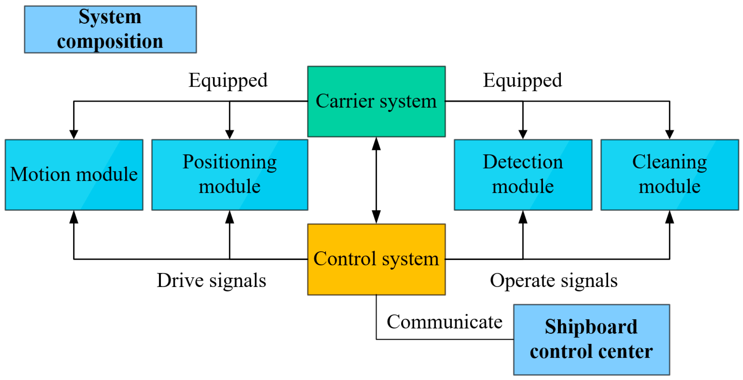
In response to the requirements for underwater detection of jacket piles, as shown in Figure 1, the designed underwater detection robot comprises several modules: the carrier system, control system, motion module, position module, detection module, and cleaning module. The carrier system primarily includes the structural frame and buoyancy blocks to carry all functional modules of the underwater detection robot. The control system controls the drive signals for the robot system, communicating with the shipboard control center. The motion module executes translational and rotational movements according to control signals. The position module utilizes multiple sensors mounted on the robot to locate damage. The underwater detection module, mainly consisting of visual equipment, is tasked with photo capture and automatic identification of structural damage. The cleaning module is equipped with underwater cleaning equipment to clean the wall.

Figure 1.
Logical diagram of the system composition.
2.3. Structural Design
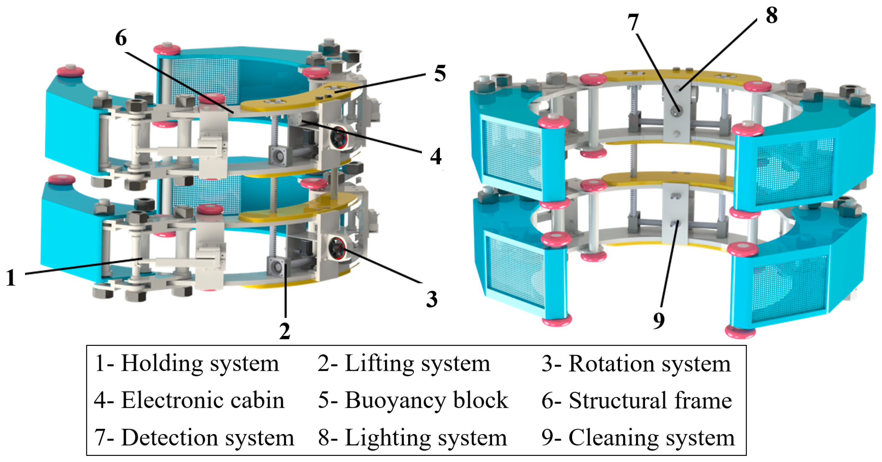
As illustrated in Figure 2, the structural design of the underwater detection robot is composed of a structural frame, a lifting system, a rotation system, a holding system, a detection system, an electronic cabin, and a cleaning system. In detail, the robot consists of two identical structural frames connected by the screw of the lifting system. The detection system, lighting system, and electronic cabin are mounted on the upper structural frame and are responsible for controlling the robot’s underwater detection, movement, and positioning capacities. The cleaning system is installed in the structural frame and tasked with performing cleaning capacity. Moreover, the robot adopts a three-segment structure of mechanical holding mechanism—carrier frame—mechanical holding mechanism, realizing holding motion through the control of the mechanical holding mechanism by electric push rods.
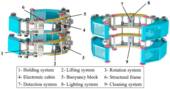
Figure 2.
Structural design of the underwater detection robot.
3. Traversal System
3.1. Locomotion Mechanics
(1) The holding mechanics
As depicted in Figure 3a, the mechanical holding system primarily consists of an electric push rod, a linkage mechanism, a holding claw, and two wheels. The thrust output from the electric push rod acts upon the levers, driving the holding claw in a gripping motion to achieve contact between the wheels and the jacket pile. This contact force ensures the robot’s stable attachment to the jacket pile.
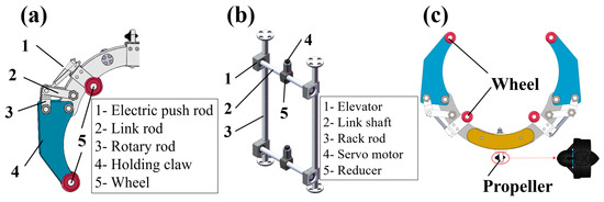
Figure 3.
Locomotion mechanics: (a) the mechanical holding mechanism; (b) the lifting mechanism; (c) the rotary mechanics.
(2) The lifting mechanics
To facilitate the robot’s vertical movement along the walls, the lifting mechanism employs a dual-gear and rack system, mainly consisting of a servo motor, reducer, elevator, rack rod, and link shaft. The torque output from the servo motor is amplified through the reducer and transmitted to the link shaft, causing the gears within the elevator to roll along the rack rod. It then drives the carrier frame of the robot to move vertically. The design of the lifting mechanism is illustrated in Figure 3b.
(3) The rotary mechanics
As shown in Figure 3c, there is a propeller mounted on the exterior of the structural frame and four wheels mounted on its interior. The thrust from the propeller pushes the structural frame to rotate along the jacket pile, while the wheels serve to reduce friction and promote propulsive motion stability. The rotation speed of the robot can be controlled by adjusting the propeller’s power.
3.2. Movement Strategy
(1) Rotary and vertical motion
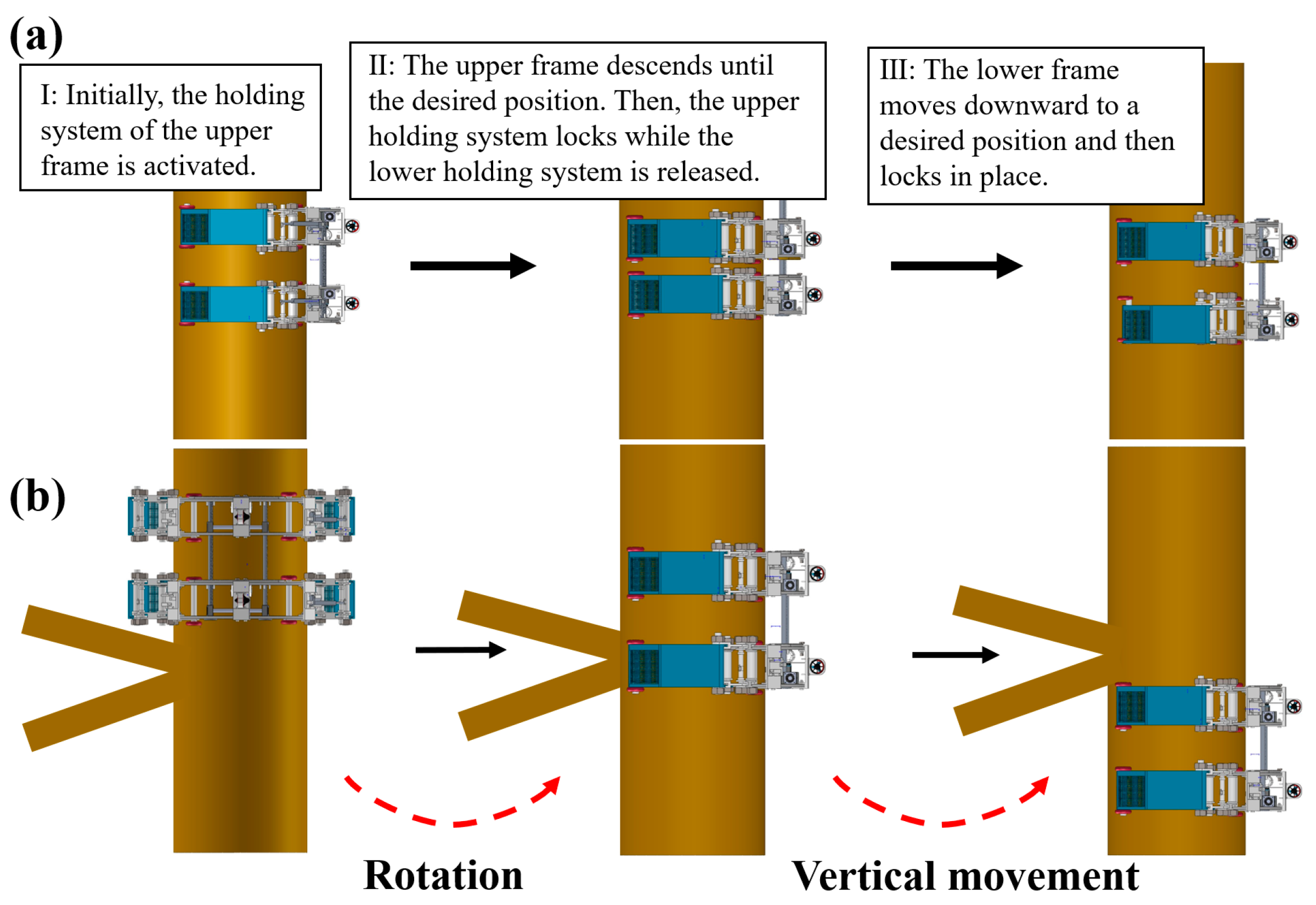
The rotary movement is facilitated by a rotary mechanism that provides tangential force, driving the robot’s wheels to move on the wall of the jacket pile. Furthermore, as illustrated in Figure 4a, for vertical motion, the holding system of the upper frame is first opened. Subsequently, the upper frame descends until it reaches the desired position. Then, the upper holding system locks while the lower holding system is released. Finally, the lower frame moves downward to a predetermined position and locks in place. By repeating the process, the robot can continuously move downward. In contrast, the movement sequences of the upper and lower frames are alternated for upward progression.
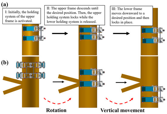
Figure 4.
The movement and obstacle avoidance: (a) the stages of the vertical motion; (b) the obstacle avoidance strategy.
(2) Obstacle avoidance strategy
The K or X truss of the jacket pile necessitates the design of the underwater detection robot with a non-fully enclosing structure, which allows the robot to avoid obstacles. Figure 4b illustrates the obstacle avoidance strategy of the underwater detection robot. When the robot encounters an obstacle that cannot be directly passed, it first utilizes the rotary mechanism to turn around until the gap in the structural frame aligns with the obstacle. Then, the lifting mechanism is engaged, allowing the robot to translate and thus avoid obstacles from the opposing side of the jacket pile.
4. Hydrodynamic Analysis of the Robot
4.1. Numerical Model
Since the robot operates in underwater environments, the effect of the flow on the robot cannot be overlooked, and this also poses higher demands on the robot’s control system. Thus, it is necessary to analyze the drag force to provide design inputs for the control system of the robot.
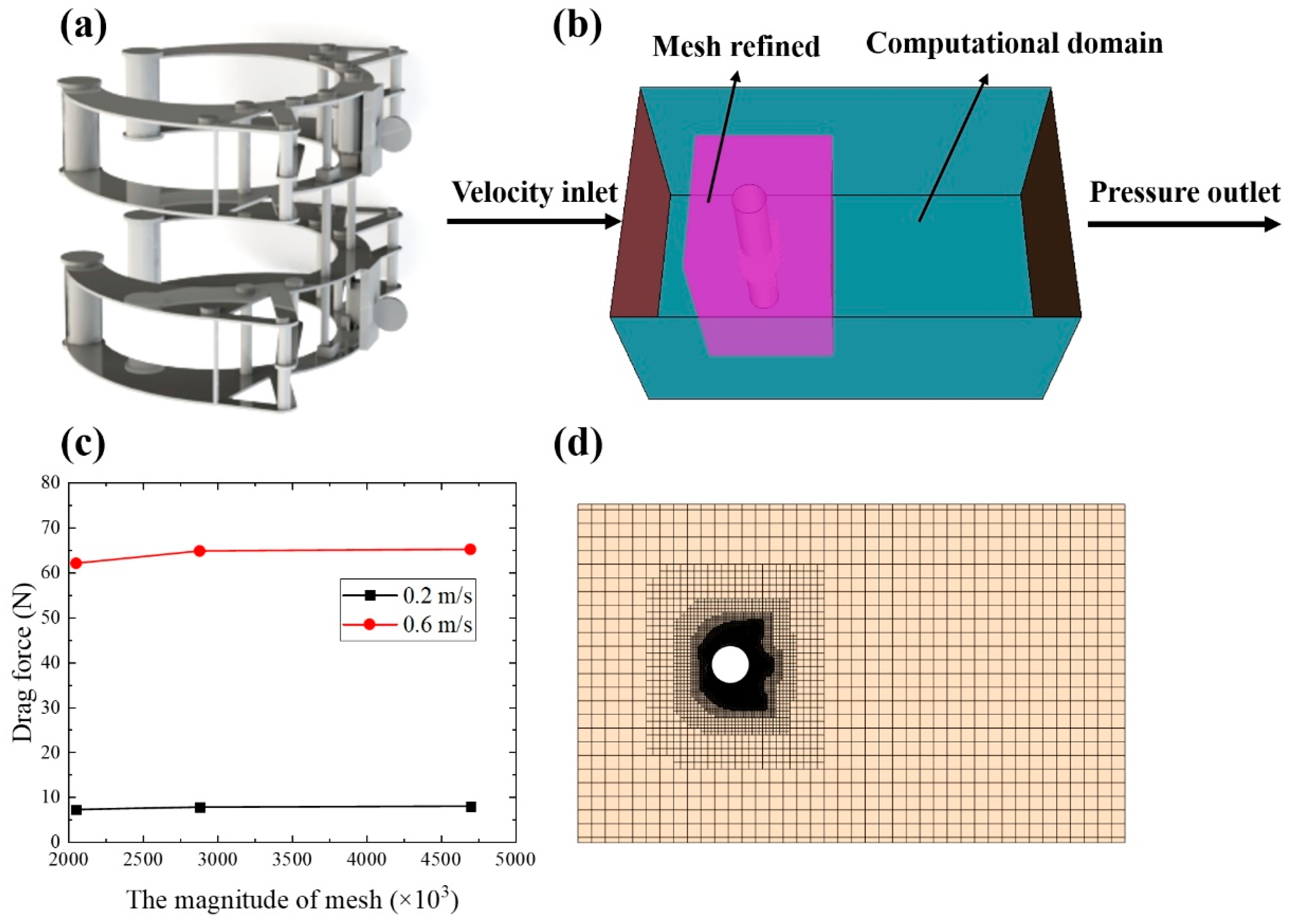
It is essential to simplify the robot model by removing minor components to reduce the computational demands for hydrodynamic analysis, and the numerical convergence is thereby easy to facilitate. The simplified model is illustrated in Figure 5a, which is then imported into Star-CCM+, as shown in Figure 5b. The size of the rectangular computational domain is 10 L × 5 L × 5 L, where L is the characteristic length of the robot. To improve numerical precision, the mesh near the robot is refined; the refinement area is 2 L × 2 L × 5 L.

Figure 5.
The numerical model of the underwater detection robot: (a) The simplified model of the robot for hydrodynamics analysis; (b) computational domain; (c) drag force vs. varied mesh size; (d) meshing model.
Hydrodynamic results are related to the magnitude of meshes. Thus, numerical models with different mesh sizes of 0.25 m, 0.125 m, and 0.05 m are analyzed under flow velocities of 0.2 m/s and 0.6 m/s to decide the optimal mesh size. The numerical results of the drag force for each case are shown in Figure 5c. As the magnitude of meshes increases, the drag force initially increases and then stabilizes. Therefore, considering computational efficiency and accuracy, the 0.125 m mesh size is chosen for meshing, as depicted in Figure 5d. Under this scheme, the mesh sizes of the computational domain, the refinement area, and the jacket pile are 0.125 m, 0.025 m, and 0.05 m, respectively. The mesh size of the robot model, which has the most significant impact on precision, is decided to be 0.01 m.
4.2. Simulation Strategy
Calculating the drag force exerted by the flow on a robot during its rotational movement presents considerable challenges. To address this complexity, the process is divided into two steps: first, calculating the drag force experienced by the robot rotating in stationary water, and then evaluating the force exerted by flowing water while the robot remains static. To assess the impact of rotational velocity, the speeds are set at 0.04 rad/s, 0.08 rad/s, 0.12 rad/s, 0.16 rad/s, and 0.2 rad/s. Furthermore, to simulate the effects of varying flow orientations, the robot model’s direction is adjusted from 0 to 360 degrees in 15-degree increments. The flow’s velocity is set at 1 m/s.
4.3. Results and Analysis of the Drag Force
The drag forces experienced by an underwater detection robot at different rotational speeds are detailed in Figure 6.
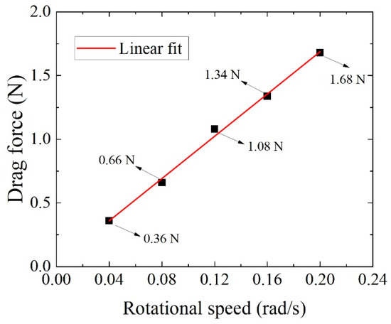
Figure 6.
Drag forces vs. various rotational speeds for the underwater detection robot.
The results indicate a direct proportionality between the drag force on the underwater detection robot and its rotational speed. The highest recorded value is only 1.68 N. This is primarily attributed to the robot’s open-frame structure, which minimizes the contact area with the flow. A linear fit of the drag force against rotational speeds yields the following:
where Fd is the drag force and the is the rotational speed.
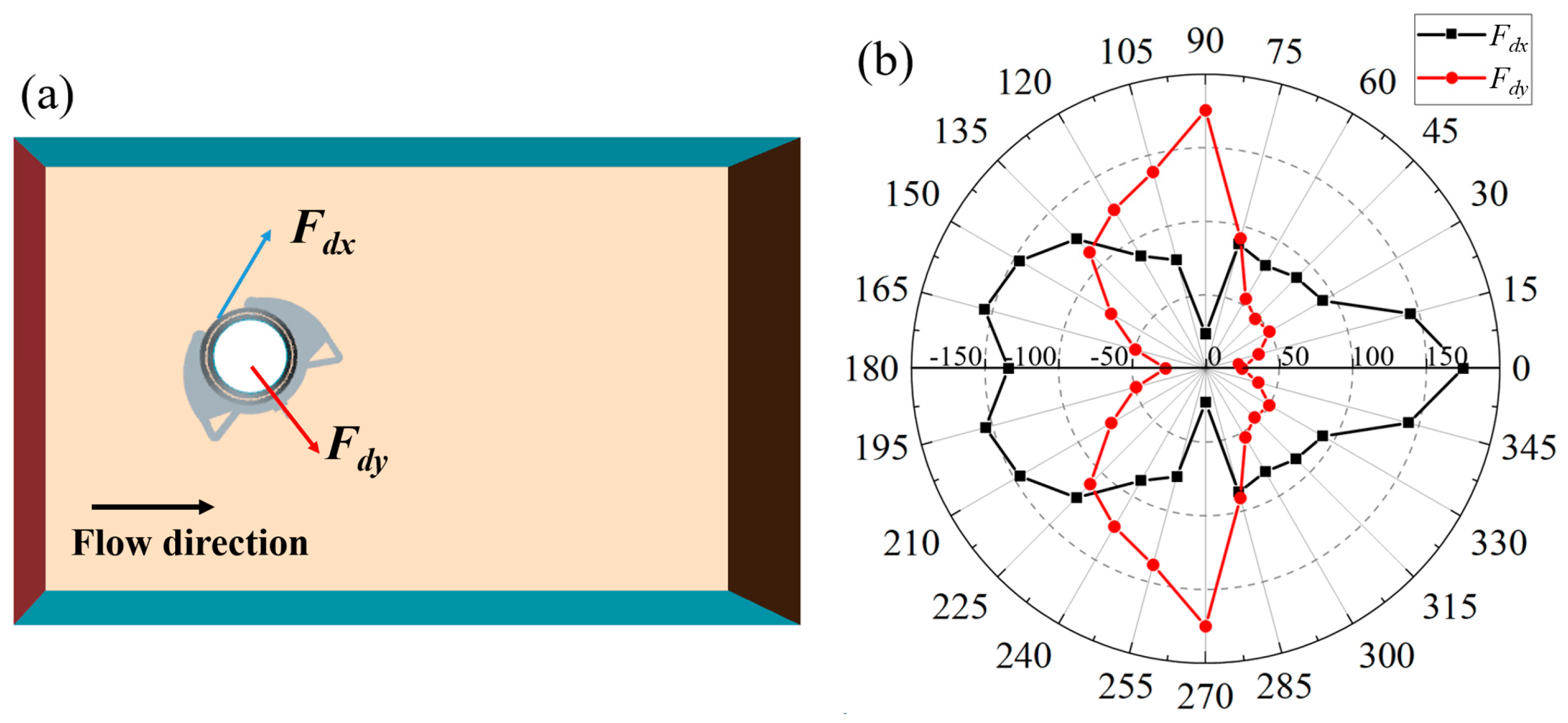
As depicted in Figure 7a, the drag force is decomposed into radial and tangential components, designated as Fdx and Fdy, respectively. This decomposition not only facilitates a thorough evaluation of the flow’s impact but also enables its integration into the control system. The drag force experienced by the underwater detection robot in a stationary state, depicted as a function of the flow direction, is illustrated in Figure 7b. Due to the robot’s symmetry, the magnitude of forces from 0° to 180° are the same as those from 180° to 360°. It indicates that the Fdx exhibits a trend of gradual decrease followed by an increase, peaking at 173.24 N at the initial position. The minimal Fdx, recorded at 7.82 N, occurs at the 90° position, marking a shift in the direction of the force. Conversely, Fdy demonstrates an initial increase followed by a decrease, with a maximum value of 174.85 N at the 90° position. Moreover, the minimum value of Fdy is 8.8 N, observed at the 0° position. A notable change in Fdy occurs at the 180° position, transitioning from resistance to propulsion.
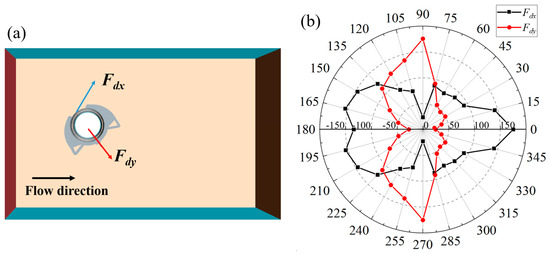
Figure 7.
The results of the drag force: (a) The drag force is decomposed into radial and tangential components; (b) The drag force on the robot at varying angles of flow.
5. Control System Design
5.1. Motion Control Algorithm
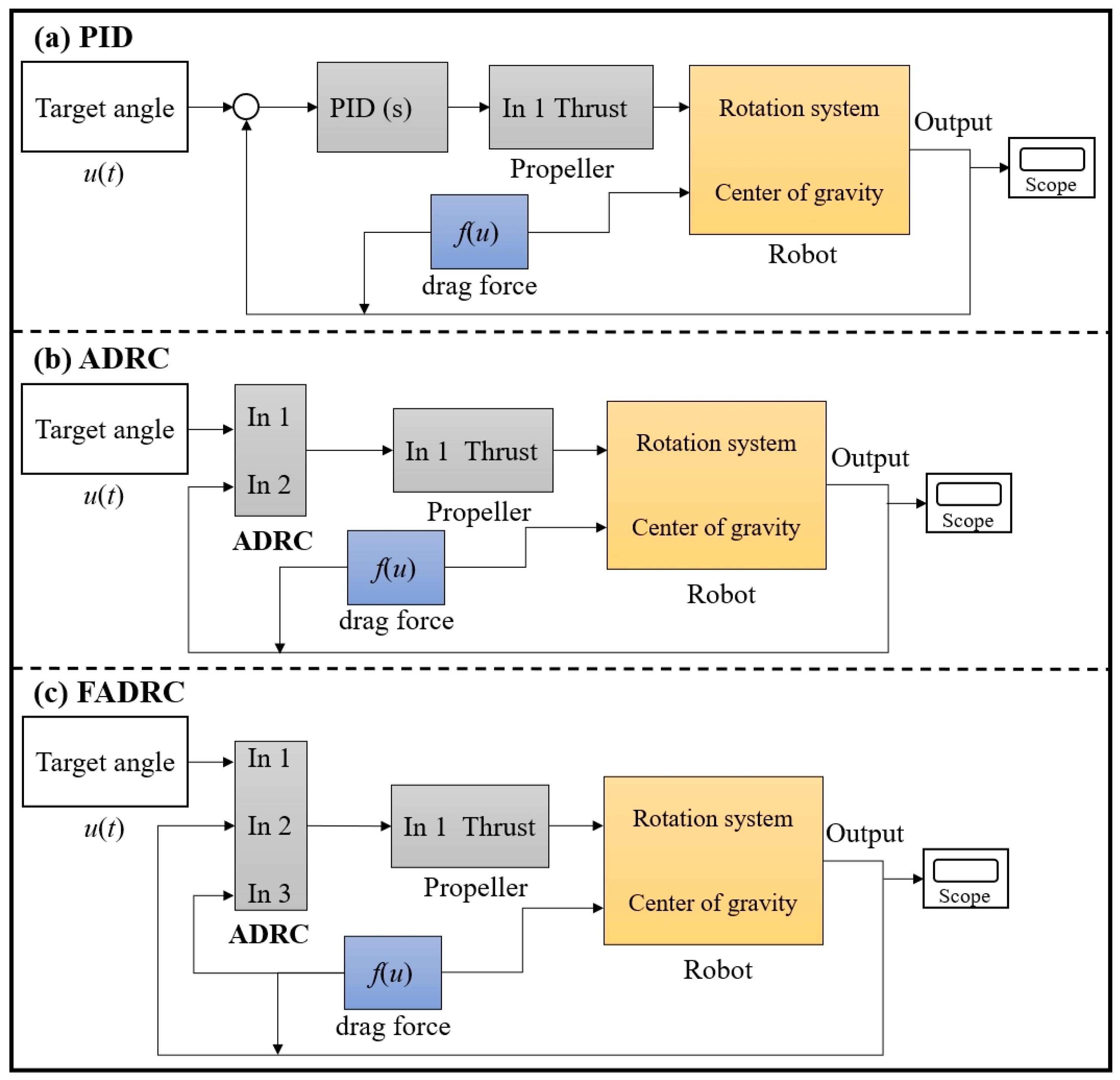
The proportional integral derivative (PID) algorithm is a common motion control algorithm for underwater robots due to its simple structure and rapid response. Nevertheless, the PID algorithm struggles to process external disturbances. To address this deficiency, the active disturbance rejection controller (ADRC) algorithm has been proposed, capable of effectively mitigating disturbances. The ADRC categorizes disturbances as either internal or external and employs a closed-loop feedback system to significantly minimize these disturbances, thereby enhancing the precision of control. The motion of the underwater detection robot along the jacket is subject to additional disturbances originating from the flow, exhibiting variability under angular alterations. These extra disturbances increase the burden on the state observer and constrain the efficacy of the ADRC. Consequently, a force-redeemed active disturbance rejection controller (FADRC) is then proposed to consider the effect of the flow and improve its precision and efficacy. Figure 8 illustrates the PID, ADRC, and FADRC control structures for the rotation angle of an underwater detection robot.
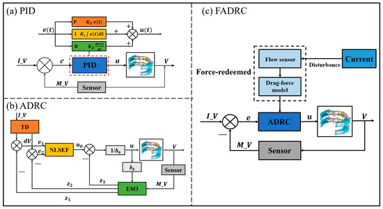
Figure 8.
The control structures of the underwater detection robot: (a) PID, (b) ADRC, (c) FADRC.
5.1.1. Proportional Integral Derivative (PID) Controller
Proportional Integral Derivative (PID) is a commonly used feedback controller. It uses three parameters to control the robot. The proportional term produces an output value (part of u(t)) that is proportional to the current error value, e(t). The constant Kp is the proportional gain, a tuning parameter. The integral term is concerned with the accumulation of past errors. If the error has been present for a while, it integrates over time. The constant Ki is the integral gain. This term aims to eliminate residual steady-state errors. The derivative term produces an output that is based on the rate of change of the error , preventing the system from overshooting the setpoint. The constant Kd is the derivative gain.
The PID controller takes the error signal e(t) from the sensor, which measures the difference between the desired and actual rotation angles, and computes the control input u(t) to correct the rotation angle of the robot. Its differential equation is expressed as follows:
where IV represents the input value of the robot’s target rotation angle, MV is the measured value of the actual rotation angle measured by the sensor, and e(t) signifies the error between the target and the actual rotation angle. Kp, Ki, Kd are the proportional gain, the integral gain, and the derivative gain, respectively.
5.1.2. Active Disturbance Rejection Controller (ADRC)
This control method is designed to deal with disturbances more effectively than traditional PID controllers. ADRC incorporates three critical components in terms of the tracking differentiator (TD), the nonlinear state error feedback control law (NLSEF), and the extended state observer (ESO). The TD is used to filter and differentiate the input signal. It can track the signal and its derivative simultaneously. The NLSF provides nonlinear feedback control based on the state errors e1 and e2. The ESO estimates the total disturbance affecting the system and compensates for it in the control signal. The control gain b characterizes the efficiency with which the control input is converted into control action. The 1/b is the inverse of the estimated total disturbance gain, which is used in the control structure to scale the output of the extended state observer (ESO). The system states that z1, z2, and z3 are internal representations used by the ADRC controller. The control action u0 is a combination of the state error feedback and the disturbance compensation, which is used to adjust the MV for the robot.
In this study, the motion system of the underwater detection robot is simplified into a second-order system. Thus, the discrete form of the second-order ADRC controller’s TD is expressed as follows:
where v1 is the tracking signal, v2 is the derivative of the tracking signal, h is the sampling step, and r is the adjustable parameter. The formula for Fhan is given by the following:
Moreover, the discrete form of the extended state observer (ESO) is as follows:
where e is the error, z1 is the observed value of the system output, z2 is the derivative of the observed value of the system output, z3 is the disturbance of the observed value of the system, y is the actual output of the system, are adjustable parameters of the observer that determine its sensitivity and speed of estimation, T is the sampling period, b is the control gain parameter, and the function fal is defined as in Equation (7):
where e is the error, α is a nonlinearity factor, and δ is the adjustable parameter of the controller.
The discrete form of the control amount introduced by the nonlinear combination feedback of the error is as follows:
where u0 is the initial control action, u is the system’s output, e1 and e2 are the errors, and are adjustable parameters of the controller, and b is the control gain parameter.
5.1.3. Force-Redeemed ADRC
The FADRC model is illustrated in Figure 8c. Through the incorporation of the flow’s velocity and direction into the drag force-angle relationship, the disturbance attributable to the flow is calculated. This approach alleviates the burden on the observer and facilitates enhanced control precision and adjustment speed for the controller.
The discrete form of the extended state observer (ESO), incorporating the drag force, is given by the following:
where represents the drag force, which is a function of the angle .
5.2. Three-Dimensional Motion Simulation Model
A three-dimensional motion simulation model of the underwater detection robot is constructed using the Simscape Multibody toolbox in Simulink. As shown in Figure 9a, the components of the underwater detection robot are modeled, with constraints and degrees of freedom added to the connections between each part. Release the rotational freedom of the propeller blades to allow them to spin and generate thrust, providing power input to the robot, as depicted in Figure 9b. The degrees of freedom for the wheels are also released, and rigid constraints are applied between other mechanisms. By connecting the main body and the propulsor, the simulation model of the robot is modeled as illustrated in Figure 9c. The disturbance is composed of the robot’s rotational resistance and the drag force from the flow. Here, the rotational resistance is considered an internal disturbance, while the resistance from water flow constitutes an external disturbance.
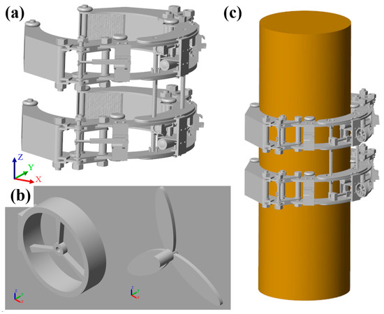
Figure 9.
Three-dimensional motion simulation model: (a) robot main body model; (b) simplified propulsor model; (c) motion simulation model of the underwater detection robot.
5.3. Control Model
Figure 10 shows the PID control model, the ADRC control model, and the FADRC control model, respectively. The main components include target input, algorithm controller, propulsor model, underwater detection robot model, and external disturbances. As shown in Figure 10a, the PID control model receives the target angle as input and produces a control signal u(t), which is used to adjust the thrust of a propeller, in turn affecting the rotation system of the robot. The rotation system is linked to the center of gravity of the robot, suggesting that the control action directly impacts the robot’s orientation. The drag force f(u) exerted by the fluid environment on the robot is also accounted for, affecting the propeller’s effectiveness. The scope is used for the output measurement in the system. Moreover, the ADRC control model is designed to handle both the target angle and drag force more effectively by actively estimating and compensating for disturbances. Similar to the PID system, it produces a thrust that influences the robot’s rotation system and center of gravity. However, it provides more robust control by handling disturbances through a feedback loop. The FADRC is an evolution of the ADRC that takes into account the impact of the drag force even more directly in the control algorithm. The FADRC receives three inputs: the target angle, the drag force, and the measured. This indicates a more complex strategy that factors in the drag force to tailor the control actions more precisely for the environment in which the robot operates.
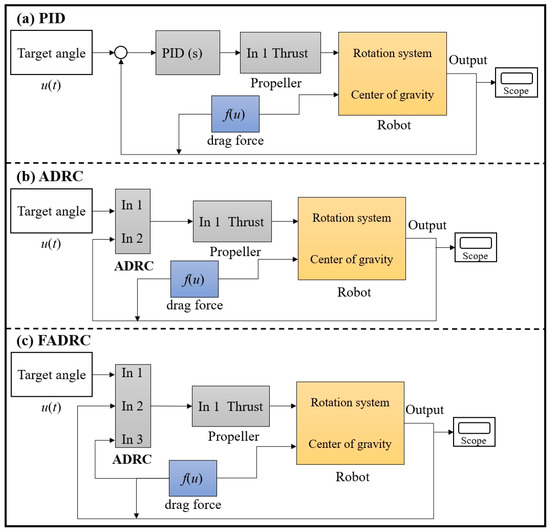
Figure 10.
Control models of the underwater detection robot.
The flow velocity is set to 1 m/s, and the total simulation duration is 100 s. To analyze the performance of the control algorithm under varying flow angles and robot rotation speeds, the robot reverses and then proceeds at two different speeds. The strategy for rotational movement is detailed as follows: At T = 0 s, the underwater detection robot is positioned initially with an angle of . At T = 20 s, the angle increases to . Finally, at T = 50 s, the angle is set to .
5.4. Control Simulation Analysis Results
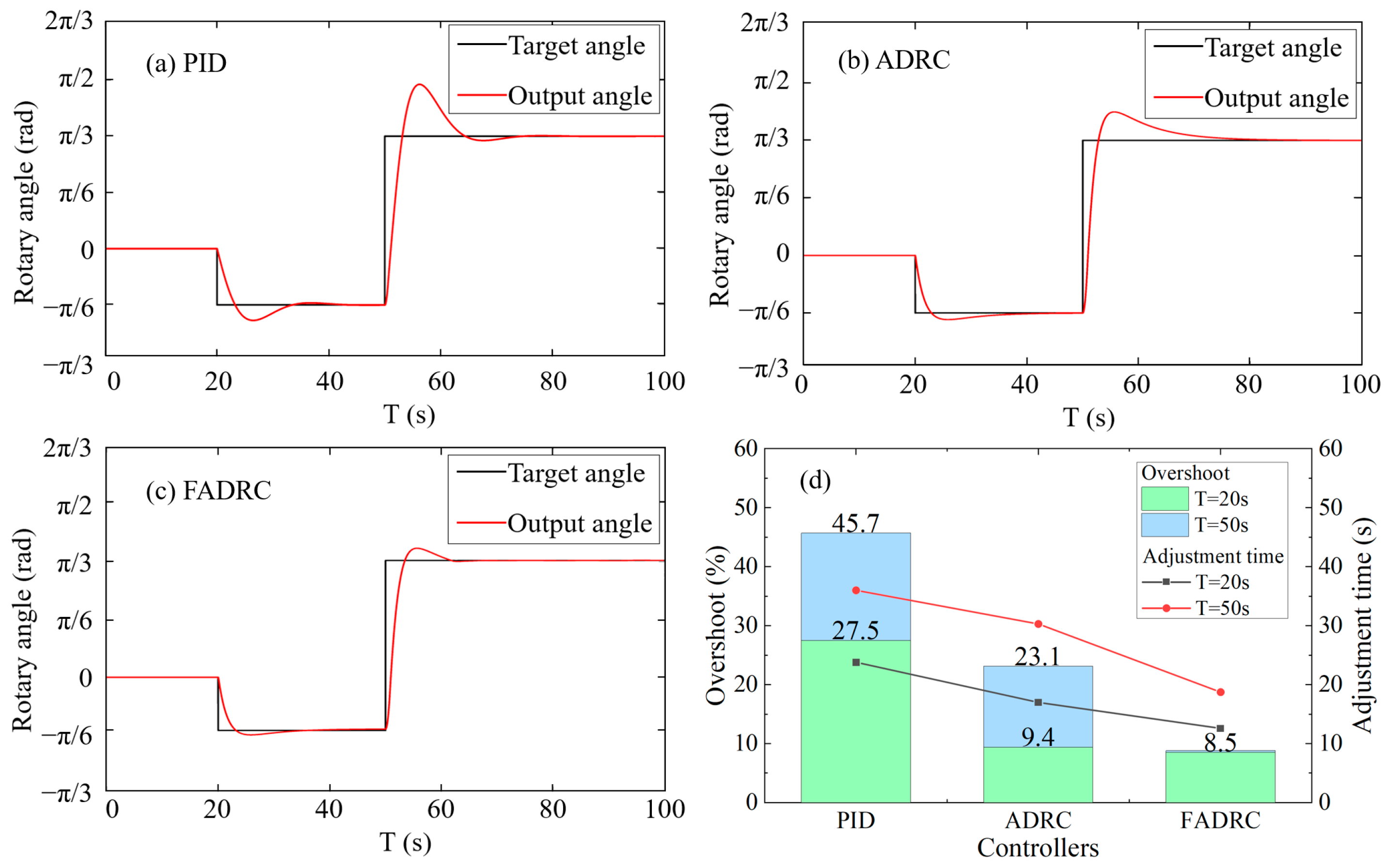
The simulation results for the three methods are depicted in Figure 11, and the comparison of the controller’s performance is provided in Figure 11d. During the movement from 0° to −30°, a reverse rotation, the robot experiences resistance due to the flow, which further introduces disturbance. After being controlled by PID, ADRC, and FADRC, the robot accurately reaches the designated positions. PID shows the largest overshoot of 27.5%, while FADRC has the smallest overshoot of 8.5%. Additionally, PID has the longest adjustment time of 23.8 s, whereas FADRC has the shortest at 12.58 s. When moving from −30° to 60° at 50 s, the robot undergoes a forward rotation. In this phase, PID shows the highest overshoot of 45.7% and FADRC the lowest at 8.8%, with PID also having the longest adjustment time of 36 s and FADRC the shortest at 18.73 s. The simulation results at 20 s are superior to those at 50 s due to the lower magnitude of resistance experienced by the robot at 20 s compared to 50 s. In all cases, the FADRC algorithm outperforms both PID and ADRC, demonstrating its effectiveness in enhancing the anti-interference capability and control performance of the underwater detection robot.

Figure 11.
Control Simulation Results: (a) PID; (b) ADRC; (c) FADRC; (d) Comparison of controllers’ performance.
6. Detection System
6.1. Detection Algorithm Based on UNet
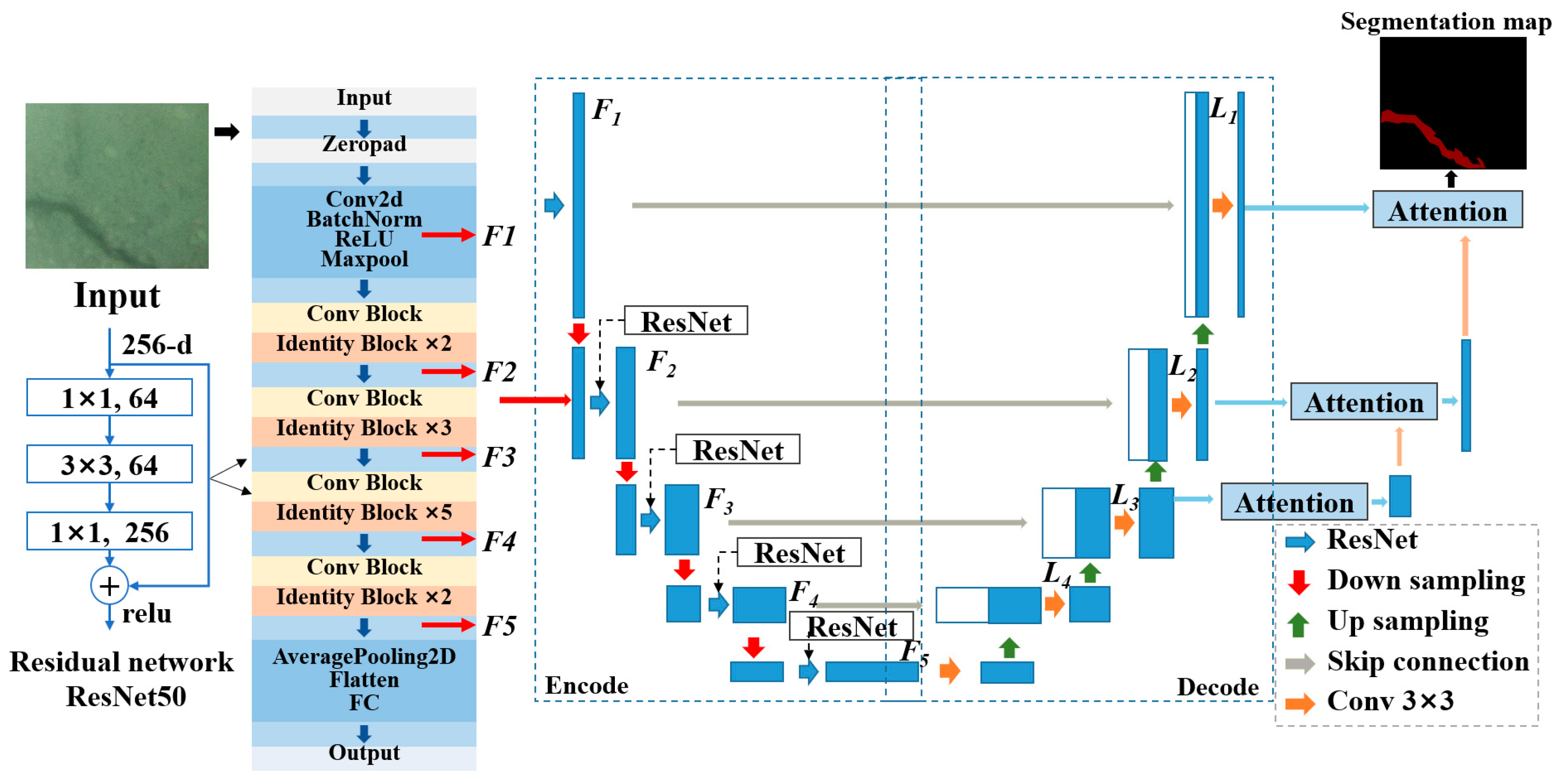
This research proposes a novel method for detecting surface cracks in underwater structures based on the UNet, as illustrated in Figure 12. The detection framework is primarily composed of three parts in terms of an encoder, a decoder, and a parallel attention module. The encoder utilizes the ResNet50 configuration instead of the conventional VGG configuration [48] to enhance feature extraction capabilities. Moreover, it incorporates a designed attention module to suppress disturbances caused by background noise, thereby increasing the precision of underwater crack feature extraction.
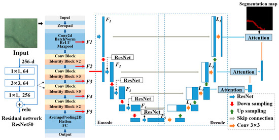
Figure 12.
Detection framework of underwater structural surface cracks.
For model training, underwater crack images are input into the encoder, where features within the crack images are extracted via the residual network ResNet50. The network begins with initial pre-processing through zero padding and a combination of convolutional, batch normalization, ReLU, and max pooling layers to extract basic features. It then advances through multiple convolutional and identity blocks, systematically refining and deepening feature extraction to capture more complex patterns. This progression includes mechanisms to prevent information loss and facilitate deeper network training without the vanishing gradient problem. Finally, the network employs average pooling and flattening to condense the extracted features, which are then fully connected for final output generation. Then, these feature maps F1 to F5 are upsampled and concatenated in the decoder to produce new feature maps L1 to L5. Concurrently, feature maps L1, L2, and L3 are fed into the parallel attention module. After processing, L3 is upsampled to match the size of L2, concatenated with L2, and then passed into the attention module associated with the L2 layer. Finally, the output of the last layer, after processing through the attention module, is obtained through a 1 × 1 convolution, yielding a prediction output identical in size to the original image.
6.2. Dataset and Data Augmentation
Regarding datasets, the commonly used crack datasets predominantly originate from above-water structures, featuring fewer disturbances and higher image quality compared to images of underwater surface cracks collected in actual environments. Hence, an underwater crack image collection experiment is conducted, simulating underwater conditions within a cistern, as shown in Figure 13. Using an underwater camera, 200 images with a resolution of 5120 pixels × 3840 pixels are captured. To mitigate potential training failures due to the large size of captured underwater crack images, the original images are cropped and resized to 512 × 512 pixels. This approach increases the number of training images and enhances the proportion of cracks within the images, which is beneficial for improving model detection accuracy. From the cropped images, 600 containing cracks are selected to compose the dataset, which is then divided into a training set and a test set at a ratio of 9:1. The images are annotated at the pixel level for supervised learning. Data augmentation techniques, including rotation, random noise addition, and scaling, are applied to quadruple the magnitude of the training set. Additionally, to validate the model’s efficacy, two other public crack datasets, CFD [49] and DeepCrack [50], are utilized as test sets to assess the model’s detection performance. The number of images used in the test phase is 600, which are the same as those in the collected underwater dataset.
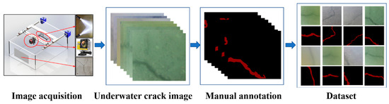
Figure 13.
Dataset of underwater structural surface cracks.
6.3. Experimental Results and Analysis
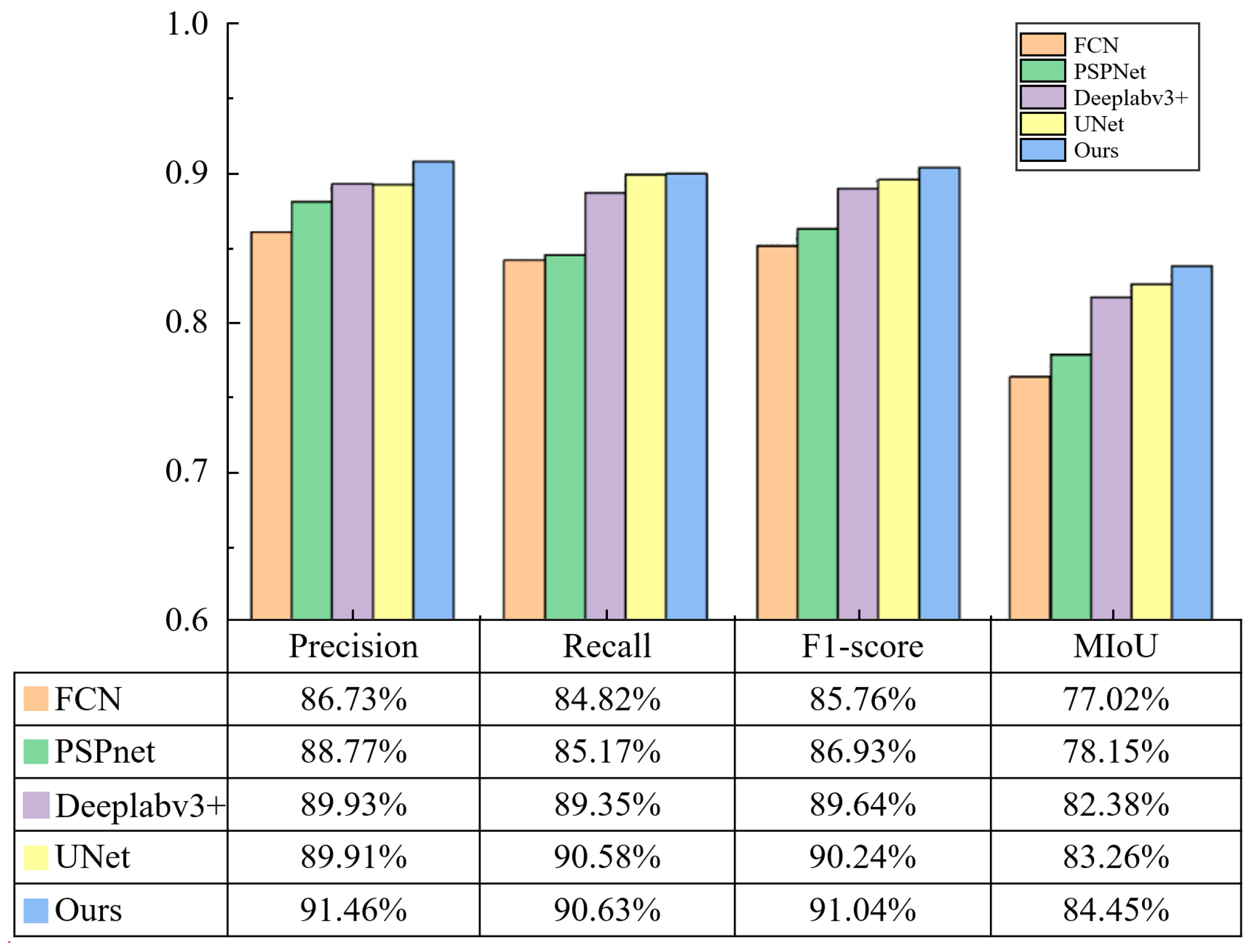
Four metrics of precision—rate of recall, mean intersection over union (MIoU), and F1-score—are employed to evaluate the detection algorithms. The superiority of the proposed algorithms is compared against UNet [43], FCN [51], PSPNet [52], and Deeplabv3 [53] algorithms. The results of different algorithms are shown in Figure 14. All algorithms indicate superior segmentation characteristics when underwater images are clear. Nevertheless, when cracks are too slender or the contrast between cracks and background is low, FCN and PSPNet results are notably inferior, with a significant loss of crack features. Deeplabv3 and UNet perform better than other algorithms but still have issues such as missing crack features, discontinuous prediction pixels, and over-segmentation. Compared to these methods, the proposed algorithm achieves smoother crack segmentation and suggests more closely matching the manually annotated results. A quantitative comparison using the four metrics of MIoU, precision, recall, and F1-score of the different algorithms is shown in Figure 15. The developed method outperformed others in all four metrics, achieving an MIoU of 84.45%, which is higher than both UNet and Deeplabv3’s 83.26% and 82.38%, respectively, and significantly surpassing FCN and PSPNet by 7.43% and 6.3%. It also scored the highest in precision, recall, and F1-score, reaching 91.46%, 90.63%, and 91.04%, respectively.
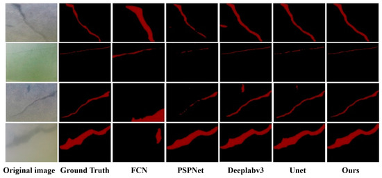
Figure 14.
The visualization of different algorithms’ results applied to the collected datasets.
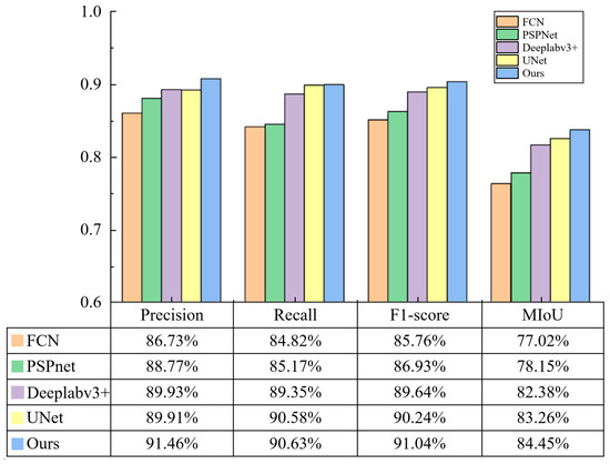
Figure 15.
Quantitative comparison using the four metrics of precision, recall, F1-score, and MIoU of the different algorithms applied to the collected datasets.
7. Conclusions
Structural concepts, a traversal system, a controller, and a detection algorithm have been developed to enable autonomous robotic underwater detection for the structures with pile foundation. The main conclusions are obtained as follows:
- (1)
- In response to the requirements for underwater detection of jacket piles, the underwater detection robot is designed to comprise a structural frame, a lifting system, a rotation system, a holding system, a detection system, an electronic cabin, and a cleaning system.
- (2)
- The robot employs dual claws, link rods, and an electric push to attach itself to the jacket pile. Rotary movement is facilitated by a propeller mechanism that provides tangential force, enabling the robot’s wheels to traverse the wall of the jacket pile. The vertical movement is achieved through the alternating movement of the robot’s upper and lower structural frames.
- (3)
- A force-redeemed active disturbance rejection controller is designed to account for the impact of water drag force. A simulation model is created in Simulink to compare the performance of the FADRC with two traditional controllers in terms of PID and ADRC. Simulation results show that the FADRC exhibits optimal performance in both overshoot and adjustment time.
- (4)
- Furthermore, a novel underwater crack detection algorithm based on the image segmentation network of UNet is developed. The proposed method achieves a mean intersection over union (MIoU) of 84.45%, surpassing UNet and Deeplabv3 by 383.26% and 82.38%, respectively, and showing improvements of 7.43% and 6.3% over FCN and PSPNet, respectively. It also demonstrates the best performance in precision, recall, and F1-score on the test set, achieving 91.46%, 90.63%, and 91.04%, respectively.
This work significantly advances the technology of autonomous robots for underwater detection in the structures with pile foundation.
Author Contributions
Conceptualization, W.Z. and Y.Y.; data curation, J.D.; formal analysis, J.D.; methodology, Y.Y.; project administration, K.Z.; resources, K.Z. and J.G.; software, W.Z. and Z.Y.; supervision, J.G.; validation, K.Z. and Z.Y.; visualization, Y.Y.; writing—original draft, Y.Y.; writing—review and editing, W.Z. All authors have read and agreed to the published version of the manuscript.
Funding
This research received no external funding.
Institutional Review Board Statement
Not applicable.
Informed Consent Statement
Not applicable.
Data Availability Statement
The data presented in this study are available on request from the corresponding author.
Conflicts of Interest
Authors Wenwei Zhang, Kun Zhu, Zhichun Yang were employed by the company CCCC Second Highway Consultants Co., Ltd. The remaining authors declare that the research was conducted in the absence of any commercial or financial relationships that could be construed as a potential conflict of interest.
References
- Xu, S.; Wang, S.; Soares, C.G. Experimental investigation on hybrid mooring systems for wave energy converters. Renew. Energy 2020, 158, 130–153. [Google Scholar] [CrossRef]
- Xu, S.; Wang, S.; Soares, C.G. Review of mooring design for floating wave energy converters. Renew. Sustain. Energy Rev. 2019, 111, 595–621. [Google Scholar] [CrossRef]
- Kang, J.; Sun, L.; Soares, C.G. Fault Tree Analysis of floating offshore wind turbines. Renew. Energy 2019, 133, 1455–1467. [Google Scholar] [CrossRef]
- Li, H.; Soares, C.G.; Huang, H.-Z. Reliability analysis of a floating offshore wind turbine using Bayesian Networks. Ocean Eng. 2020, 217, 107827. [Google Scholar] [CrossRef]
- Li, H.; Huang, C.-G.; Soares, C.G. A real-time inspection and opportunistic maintenance strategies for floating offshore wind turbines. Ocean Eng. 2022, 256, 111433. [Google Scholar] [CrossRef]
- Li, H.; Soares, C.G. Assessment of failure rates and reliability of floating offshore wind turbines. Reliab. Eng. Syst. Saf. 2022, 228, 108777. [Google Scholar] [CrossRef]
- Zhang, F.; Chen, X.; Yan, J.; Gao, X. Countermeasures for local scour around offshore wind turbine monopile foundations: A review. Appl. Ocean Res. 2023, 141, 103764. [Google Scholar] [CrossRef]
- Zhang, J.; Wang, H. Development of offshore wind power and foundation technology for offshore wind turbines in China. Ocean Eng. 2022, 266, 113256. [Google Scholar] [CrossRef]
- Chen, J.; Qu, Y.; Sun, Z. Protection mechanisms; countermeasures, assessments and prospects of local scour for cross-sea bridge foundation: A review. Ocean Eng. 2023, 288, 116145. [Google Scholar] [CrossRef]
- Beckett, A.; Kordick, M.F. Risk factors for dive injury: A survey study. Res. Sports Med. 2007, 15, 201–211. [Google Scholar] [CrossRef]
- Casadesús, J.M.; Aguirre, F.; Carrera, A.; Boadas-Vaello, P.; Serrando, M.T.; Reina, F. Diving-related fatalities: Multidisciplinary, experience-based investigation. Forensic Sci. Med. Pathol. 2019, 15, 224–232. [Google Scholar] [CrossRef] [PubMed]
- Bonnin-Pascual, F.; Ortiz, A. On the use of robots and vision technologies for the inspection of vessels: A survey on recent advances. Ocean. Eng. 2019, 190, 106420. [Google Scholar] [CrossRef]
- Albitar, H.; Dandan, K.; Ananiev, A.; Kalaykov, I.; Robotics, U. Underwater robotics: Surface cleaning technics, adhesion and locomotion systems. Int. J. Adv. Robot. Syst. 2016, 13. [Google Scholar] [CrossRef]
- Song, C.; Cui, W. Review of Underwater Ship Hull Cleaning Technologies. J. Mar. Sci. Appl. 2020, 19, 415–429. [Google Scholar] [CrossRef]
- Yang, C.; Liu, S.; Su, H.; Zhang, L.; Xia, Q.; Chen, Y. Review of underwater adsorptive-operating robots: Design and application. Ocean Eng. 2024, 294, 116794. [Google Scholar] [CrossRef]
- Xu, Y.; He, K.; Zhao, W.; Fang, H.; Zuo, Q.; Li, Z. A Novel Design of a Wall-Climbing Robot and Experimental Study on Magnetic Wheels. In Proceedings of the 2021 International Conference on Computer, Control and Robotics (ICCCR), Shanghai, China, 8–10 January 2021; pp. 60–65. [Google Scholar]
- Nguyen, S.T.; La, H.M. A Climbing Robot for Steel Bridge Inspection. J. Intell. Robot. Syst. 2021, 102, 75. [Google Scholar] [CrossRef]
- Zhu, Y.; Zhou, R.; Yang, G.; Zhu, Y.; Hu, D. Experimental and numerical study of the adsorption performance of a vortex suction device using water-swirling flow. Sci. China Technol. Sci. 2020, 63, 931–942. [Google Scholar] [CrossRef]
- Lu, X.; Guo, D.; Chen, Y. Design and optimization of the magnetic adsorption mechanism of a pipeline-climbing robot. J. Mech. Sci. Technol. 2021, 35, 5161–5171. [Google Scholar]
- Hachicha, S.; Zaoui, C.; Dallagi, H.; Nejim, S.; Maalej, A. Innovative design of an underwater cleaning robot with a two arm manipulator for hull cleaning. Ocean Eng. 2019, 181, 303–313. [Google Scholar] [CrossRef]
- Ferreira, C.Z.; Cardoso, R.; Meza, M.E.M.; Ávila, J.P.J. Controlling tracking trajectory of a robotic vehicle for inspection of underwater structures. Ocean Eng. 2018, 149, 373–382. [Google Scholar] [CrossRef]
- Backus, S.B.; Onishi, R.; Bocklund, A.; Berg, A.; Contreras, E.D.; Parness, A. Design and testing of the JPL-Nautilus Gripper for deep-ocean geological sampling. J. Field Robot. 2020, 37, 972–986. [Google Scholar] [CrossRef]
- Gotts, C.; Hall, B.; Beaumont, O.; Chen, Z.; Cleaver, W.; England, J.; White, D.; Thornton, B. Development of a prototype autonomous inspection robot for offshore riser cables. Ocean Eng. 2022, 257, 111485. [Google Scholar] [CrossRef]
- Fan, J.; Yang, C.; Chen, Y.; Wang, H.; Huang, Z.; Shou, Z.; Jiang, P.; Wei, Q. An underwater robot with self-adaption mechanism for cleaning steel pipes with variable diameters. Ind. Robot Int. J. 2018, 45, 193–205. [Google Scholar] [CrossRef]
- Chen, Y.; Liu, S.; Zhang, L.; Zheng, P.; Yang, C. Study on the adsorption performance of underwater propeller-driven Bernoulli adsorption device. Ocean Eng. 2022, 266, 112724. [Google Scholar] [CrossRef]
- Chen, L.; Cui, R.; Yan, W.; Xu, H.; Zhao, H.; Li, H. Design and climbing control of an underwater robot for ship hull cleaning. Ocean Eng. 2023, 274, 114024. [Google Scholar] [CrossRef]
- Kimball, M.; Amit, A.; Gmerek, A.; Collins, P.; Wheateley, A.; Shah, K.; Liu, J.; Dissanayake, M.; Caroll, J.; Plastropoulos, A.; et al. Mooring chain climbing robot for NDT inspection applications. In Proceedings of the Climbing and Walking Robots and Support Technologies for Mobile Machines (CLAWAR), Panama City, Panama, 12 September 2018; World Scientific Publishing: Singapore, 2018; pp. 184–198. Available online: https://openresearch.lsbu.ac.uk/item/8696z (accessed on 17 June 2024).
- Le, A.V.; Veerajagadheswar, P.; Kyaw, P.T.; Muthugala, M.A.V.J.; Elara, M.R.; Kuma, M.; Nhan, N.H.K. Towards optimal hydro-blasting in reconfigurable climbing system for corroded ship hull cleaning and maintenance. Expert Syst. Appl. 2021, 170, 114519. [Google Scholar] [CrossRef]
- Sakagami, N.; Ishimaru, K.; Kawamura, S.; Shibata, M.; Onishi, H.; Murakami, S. Development of an Underwater Robotic Inspection System using Mechanical Contact. J. Field Robot. 2013, 30, 624–640. [Google Scholar] [CrossRef]
- Wu, Y.; Ta, X.; Xiao, R.; Wei, Y.; An, D.; Li, D. Survey of underwater robot positioning navigation. Appl. Ocean Res. 2019, 90, 101845. [Google Scholar] [CrossRef]
- Allegro, G.; Fascista, A.; Coluccia, A. Acoustic Dual-function communication and echo-location in inaudible band. Sensors 2022, 22, 1284. [Google Scholar] [CrossRef]
- Mangalathu, S.; Jeon, J.-S. Ground motion-dependent rapid damage assessment of structures based on wavelet transform and image analysis techniques. J. Struct. Eng. 2020, 146, 04020230. [Google Scholar] [CrossRef]
- Akagic, A.; Buza, E.; Omanovic, S.; Karabegovic, A. Pavement crack detection using Otsu thresholding for image segmentation. In Proceedings of the 2018 41st International Convention on Information and Communication Technology, Electronics and Microelectronics (MIPRO), Opatija, Croatia, 21–25 May 2018; IEEE: New York, NY, USA, 2018; pp. 1092–1097. [Google Scholar]
- Xu, X.; Wu, B.; Xie, L.; Teixeira, Â.P.; Yan, X. A novel ship speed and heading estimation approach using radar sequential images. IEEE Trans. Intell. Transp. Syst. 2023, 24, 11107–11120. [Google Scholar] [CrossRef]
- Abdel-Qader, I.; Abudayyeh, O.; Kelly, M.E. Analysis of edge-detection techniques for crack identification in bridges. J. Comput. Civ. Eng. 2003, 17, 255–263. [Google Scholar] [CrossRef]
- Huang, Y.; Zhuo, Q.; Fu, J.; Liu, A. Research on evaluation method of underwater image quality and performance of underwater structure defect detection model. Eng. Struct. 2024, 306, 117797. [Google Scholar] [CrossRef]
- Xu, X.; Wu, B.; Teixeira, Â.P.; Yan, X.; Soares, C.G. Integration of Radar Sequential Images and AIS for Ship Speed and Heading Estimation under Uncertainty. IEEE Trans. Intell. Transp. Syst. 2023, 25, 5688–5702. [Google Scholar] [CrossRef]
- Ye, H.; Li, W.; Lin, S.; Ge, Y.; Lv, Q. A framework for fault detection method selection of oceanographic multi-layer winch fibre rope arrangement. Measurement 2024, 226, 114168. [Google Scholar] [CrossRef]
- Cha, Y.J.; Choi, W.; Suh, G.; Mahmoudkhani, S.; Büyüköztürk, O. Autonomous structural visual inspection using region-based deep learning for detecting multiple damage types. Comput.-Aided Civ. Infrastruct. Eng. 2018, 33, 731–747. [Google Scholar] [CrossRef]
- Ren, S.; He, K.; Girshick, R.; Sun, J. Faster R-CNN: Towards real-time object detection with region proposal networks. IEEE Trans. Pattern Anal. Mach. Intell. 2016, 39, 1137–1149. [Google Scholar] [CrossRef]
- Fan, X.; Wu, J.; Shi, P.; Zhang, X.; Xie, Y. A novel automatic dam crack detection algorithm based on local-global clustering. Multimed. Tools Appl. 2018, 77, 26581–26599. [Google Scholar] [CrossRef]
- Xiong, C.; Zayed, T.; Abdelkader, E.M. A novel YOLOv8-GAM-Wise-IoU model for automated detection of bridge surface cracks. Constr. Build. Mater. 2024, 414, 135025. [Google Scholar] [CrossRef]
- Ronneberger, O.; Fischer, P.; Brox, T. U-net: Convolutional networks for biomedical image segmentation. In Proceedings of the Medical Image Computing and Computer-Assisted Intervention–MICCAI 2015: 18th International Conference, Munich, Germany, 5–9 October 2015; Proceedings, Part III 18. Springer: Cham, Switzerland, 2015; pp. 234–241. [Google Scholar]
- He, K.; Zhang, X.; Ren, S.; Sun, J. Deep residual learning for image recognition. In Proceedings of the IEEE Conference on Computer Vision and Pattern Recognition, Las Vegas, NV, USA, 27–30 June 2016; pp. 770–778. [Google Scholar]
- Orhei, C.; Vasiu, R. An analysis of extended and dilated filters in sharpening algorithms. IEEE Access 2023, 11, 81449–81465. [Google Scholar] [CrossRef]
- Ancuti, C.O.; Ancuti, C.; De Vleeschouwer, C.; Bekaert, P. Color balance and fusion for underwater image enhancement. IEEE Trans. Image Process. 2017, 27, 379–393. [Google Scholar] [CrossRef] [PubMed]
- Ancuti, C.; Ancuti, C.O.; Haber, T.; Bekaert, P. Enhancing underwater images and videos by fusion. In Proceedings of the 2012 IEEE Conference on Computer Vision and Pattern Recognition, Providence, RI, USA, 16–21 June 2012; IEEE: New York, NY, USA, 2012; pp. 81–88. [Google Scholar]
- Simonyan, K.; Zisserman, A. Very deep convolutional networks for large-scale image recognition. arXiv 2014, arXiv:1409.1556. [Google Scholar]
- Shi, Y.; Cui, L.; Qi, Z.; Meng, F.; Chen, Z. Automatic road crack detection using random structured forests. IEEE Trans. Intell. Transp. Syst. 2016, 17, 3434–3445. [Google Scholar] [CrossRef]
- Liu, Y.; Yao, J.; Lu, X.; Xie, R.; Li, L. DeepCrack: A deep hierarchical feature learning architecture for crack segmentation. Neurocomputing 2019, 338, 139–153. [Google Scholar] [CrossRef]
- Yang, X.; Li, H.; Yu, Y.; Luo, X.; Huang, T.; Yang, X. Automatic pixel-level crack detection and measurement using fully convolutional network. Comput.-Aided Civ. Infrastruct. Eng. 2018, 33, 1090–1109. [Google Scholar] [CrossRef]
- Zhao, H.; Shi, J.; Qi, X.; Wang, X.; Jia, J. Pyramid scene parsing network. In Proceedings of the IEEE Conference on Computer Vision and Pattern Recognition, Honolulu, HI, USA, 21–26 July 2017; pp. 2881–2890. [Google Scholar]
- Chen, L.-C.; Papandreou, G.; Schroff, F.; Adam, H. Rethinking atrous convolution for semantic image segmentation. arXiv 2017, arXiv:1706.05587. [Google Scholar]


Disclaimer/Publisher’s Note: The statements, opinions and data contained in all publications are solely those of the individual author(s) and contributor(s) and not of MDPI and/or the editor(s). MDPI and/or the editor(s) disclaim responsibility for any injury to people or property resulting from any ideas, methods, instructions or products referred to in the content. |
© 2024 by the authors. Licensee MDPI, Basel, Switzerland. This article is an open access article distributed under the terms and conditions of the Creative Commons Attribution (CC BY) license (https://creativecommons.org/licenses/by/4.0/).